

Ricoh S-P2 Service Manual

Model S-P2
Machine Code: M001
SERVICE MANUAL
September, 2008
Subject to change


Safety, Conventions, Trademarks
Safety
Prevention of Physical Injury
1. Before disassembling or assembling parts of the printer and peripherals, make sure that the printer
power cord is unplugged.
2. The wall outlet should be near the printer and easily accessible.
3. Note that some components of the printer and the paper tray unit are supplied with electrical voltage
even if the main power switch is turned off.
4. If any adjustment or operation check has to be made with exterior covers off or open while the main
switch is turned on, keep hands away from electrified or mechanically driven components.
5. The inside and the metal parts of the fusing unit become extremely hot while the printer is operating.
Be careful to avoid touching those components with your bare hands.
6. To prevent a fire or explosion, keep the machine away from flammable liquids, gases, and aerosols.
Health Safety Conditions
Toner and developer are non-toxic, but if you get either of them in your eyes by accident, it may cause
temporary eye discomfort. Try to remove with eye drops or flush with water as first aid. If unsuccessful, get
medical attention.
Observance of Electrical Safety Standards
The printer and its peripherals must be installed and maintained by a customer service representative who
has completed the training course on those models.
Safety and Ecological Notes For Disposal
1. Do not incinerate toner bottles or used toner. Toner dust may ignite suddenly when exposed to an
open flame.
2. Dispose of used toner, developer, and organic photoconductors in accordance with local regulations.
(These are non-toxic supplies.)
3. Dispose of replaced parts in accordance with local regulations.
4. When keeping used lithium batteries in order to dispose of them later, do not put more than 100
batteries per sealed box. Storing larger numbers or not sealing them apart may lead to chemical
reactions and heat build-up.
1

• The controller board in this machine contains a lithium battery.
• The danger of explosion exists if a battery of this type is incorrectly replaced. Replace only with the
same or an equivalent type of battery recommended by the manufacturer.
• Dispose of batteries in accordance with the manufacturer's instructions and local laws and regulations.
LASER SAFETY
The Center for Devices and Radiological Health (CDRH) prohibits the repair of laser-based optical units
in the field. The optical housing unit can only be repaired in a factory or at a location with the requisite
equipment. The laser subsystem is replaceable in the field by a qualified Customer Engineer. The laser
chassis is not repairable in the field. Customer engineers are therefore directed to return all chassis and
laser subsystems to the factory or service depot when replacement of the optical subsystem is required.
• Use of controls, or adjustment, or performance of procedures other than those specified in this manual
may result in hazardous radiation exposure.
• Turn off the main switch before attempting any of the procedures in the Laser Unit section. Laser beams
can seriously damage your eyes.
Caution Labels
2
Conventions and Trademarks
Conventions
Symbol What it means
* Refer to section number
See Core Tech Manual for details
Screw
Connector
E-ring
C-ring
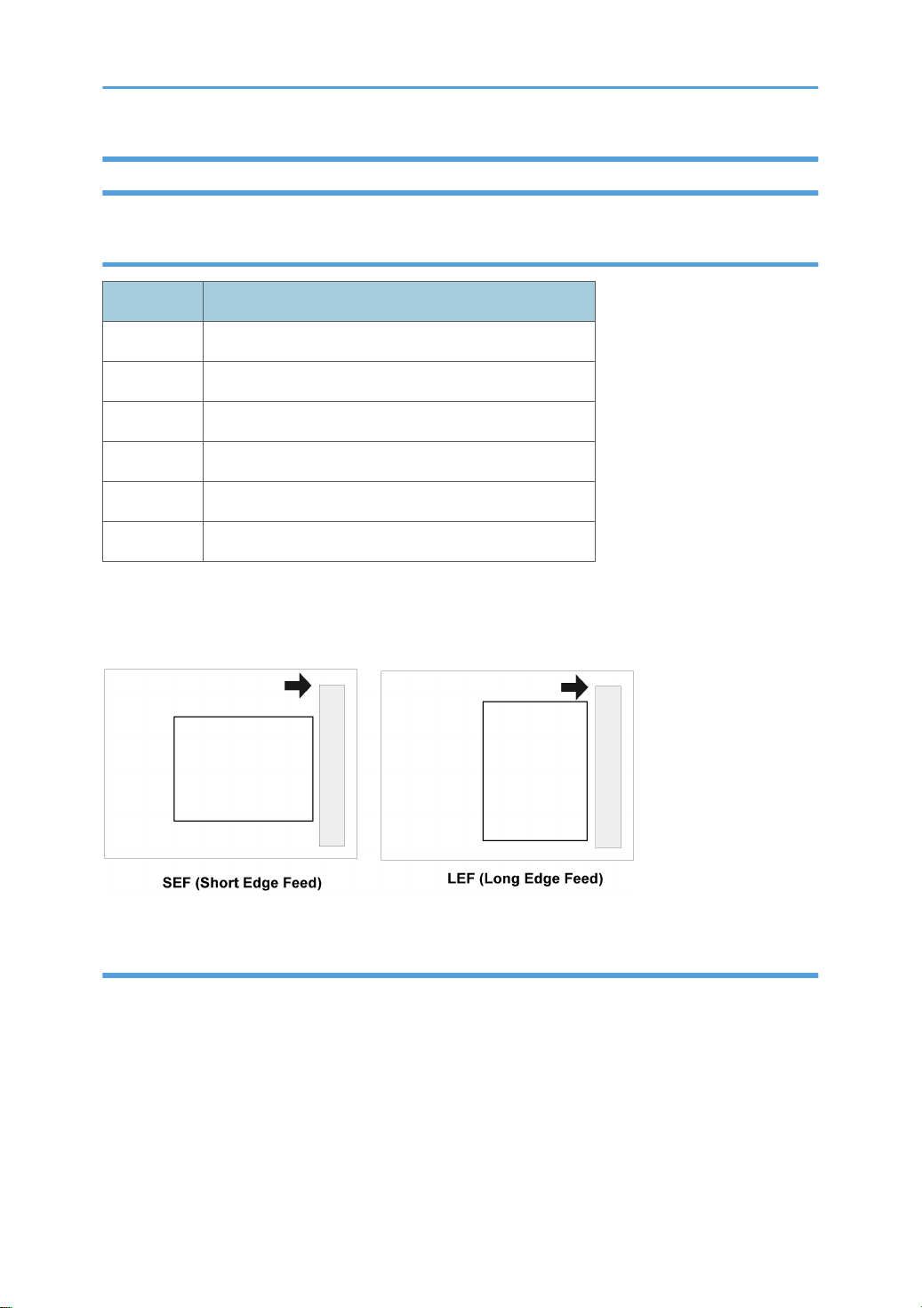
The following notations are used in text to describe the direction of paper feed: lengthwise and sideways.
The annotations “SEF” and “LEF” denote “Short Edge Feed” and “Long Edge Feed". (The arrows indicate
the direction of paper feed.)
Trademarks
Microsoft®, Windows®, and MS-DOS® are registered trademarks of Microsoft Corporation in the United
States and /or other countries.
PostScript® is a registered trademark of Adobe Systems, Incorporated.
PCL® is a registered trademark of Hewlett-Packard Company.
Ethernet® is a registered trademark of Xerox Corporation.
PowerPC® is a registered trademark of International Business Machines Corporation.
3

Other product names used herein are for identification purposes only and may be trademarks of their
respective companies. We disclaim any and all rights involved with those marks.
This manual uses several symbols and some simple abbreviations.
4

TABLE OF CONTENTS
Safety, Conventions, Trademarks......................................................................................................................1
Safety..............................................................................................................................................................1
Conventions and Trademarks........................................................................................................................3
1. Installation
Installation Requirements.................................................................................................................................11
Environment..................................................................................................................................................11
Machine Level .............................................................................................................................................12
Required Space ..........................................................................................................................................12
Power Supply ..............................................................................................................................................12
Machine Installation ........................................................................................................................................14
Data Overwrite Security Unit Installation.......................................................................................................15
Installation....................................................................................................................................................15
Checking and Completing the Installation.................................................................................................16
2. Preventive Maintenance
User Maintenance............................................................................................................................................17
Service Maintenance.......................................................................................................................................18
3. Replacement and Adjustment
General.............................................................................................................................................................21
Precautions on Disassembly .......................................................................................................................21
Releasing Plastic Latches.............................................................................................................................22
After servicing the machine.........................................................................................................................22
Special Tools ...................................................................................................................................................24
Covers...............................................................................................................................................................25
Upper Cover................................................................................................................................................25
Left Cover......................................................................................................................................................26
By-Pass Tray Unit.........................................................................................................................................26
Front Cover...................................................................................................................................................27
Right Cover...................................................................................................................................................28
Laser Unit..........................................................................................................................................................29
Caution Decal Locations ............................................................................................................................29
Polygon Mirror Motor ................................................................................................................................29
Laser Synchronization Detector..................................................................................................................30
Laser Unit......................................................................................................................................................31
5

Laser Diode Unit...........................................................................................................................................32
Laser Beam Pitch Adjustment ......................................................................................................................33
Transfer Roller ..................................................................................................................................................35
Toner End Sensor ............................................................................................................................................36
Fusing................................................................................................................................................................37
Fusing Unit....................................................................................................................................................37
Hot Roller and Fusing Lamp .......................................................................................................................37
Pressure Roller..............................................................................................................................................40
Thermistor and Thermostat .........................................................................................................................40
Hot Roller Strippers .....................................................................................................................................41
Paper Feed........................................................................................................................................................42
Paper Feed Roller .......................................................................................................................................42
Friction Pad ..................................................................................................................................................43
By-pass Tray.....................................................................................................................................................44
Printer Controller Board ..................................................................................................................................45
Engine Board ...................................................................................................................................................46
Main Motor......................................................................................................................................................47
Clutches.............................................................................................................................................................48
By-pass Feed Clutch and Relay Clutch......................................................................................................48
Paper Feed Clutch and Registration Clutch...............................................................................................49
PSU, HVPS........................................................................................................................................................51
Fans...................................................................................................................................................................53
Cooling Fan..................................................................................................................................................53
PSU Fan........................................................................................................................................................53
4. Troubleshooting
Service Call Conditions...................................................................................................................................55
Summary.......................................................................................................................................................55
SC Code Descriptions.................................................................................................................................55
Error Messages................................................................................................................................................69
General Troubleshooting.................................................................................................................................75
Image Adjustment........................................................................................................................................75
Electrical Defects..........................................................................................................................................75
Skew Adjustment..........................................................................................................................................78
6

Streaks in the Sub Scan Direction...............................................................................................................78
Miscellaneous Problems..............................................................................................................................79
5. Service Tables
Service Program Mode ..................................................................................................................................81
Service Program Mode: Overview.............................................................................................................81
Printer Controller Service Mode ....................................................................................................................83
Bit Switch Programming...............................................................................................................................83
Service Mode Menu ("1. Service Menu").................................................................................................83
Printer Engine Service Mode...........................................................................................................................87
Service Mode Table....................................................................................................................................87
Firmware Update...........................................................................................................................................145
Type Of Firmware.....................................................................................................................................145
Precautions.................................................................................................................................................145
Machine Firmware Update......................................................................................................................146
NVRAM Data Upload/Download..............................................................................................................148
Uploading NVRAM Data.........................................................................................................................148
Downloading NVRAM Data....................................................................................................................149
SD Card Application Move..........................................................................................................................151
Overview....................................................................................................................................................151
Move Exec.................................................................................................................................................151
Undo Exec..................................................................................................................................................152
Controller Self Test at Power-On..................................................................................................................154
Menu Mode ..................................................................................................................................................155
Controller Board DIP Switches ....................................................................................................................160
Card Save Function.......................................................................................................................................161
Overview....................................................................................................................................................161
Procedure...................................................................................................................................................161
Error Messages..........................................................................................................................................163
6. Details
Overview........................................................................................................................................................165
Mechanical Component Layout ..............................................................................................................165
Paper Path .................................................................................................................................................166
Board Structure..............................................................................................................................................167
7

Block Diagram ..........................................................................................................................................167
Controller Board .......................................................................................................................................167
Printing Process..............................................................................................................................................169
Overview ...................................................................................................................................................169
Laser Exposure ..........................................................................................................................................170
Cartridge Overview .................................................................................................................................173
Drum Charge ............................................................................................................................................174
Development..............................................................................................................................................174
Toner End Detection .................................................................................................................................176
Paper Feed.....................................................................................................................................................181
Overview ...................................................................................................................................................181
Paper Tray .................................................................................................................................................182
By-pass tray ..............................................................................................................................................187
Image Fusing and Paper Exit........................................................................................................................188
Overview ...................................................................................................................................................188
Fusing Drive ..............................................................................................................................................189
Fusing Entrance and Guide Shaft ............................................................................................................189
Pressure Roller ..........................................................................................................................................190
New Fusing Unit Detection ......................................................................................................................191
Fusing Temperature Control ....................................................................................................................192
Paper Exit ..................................................................................................................................................194
Energy Saver Mode .................................................................................................................................194
Controller Functions.......................................................................................................................................196
7. Specifications
Basic Specifications.......................................................................................................................................197
General Specifications..............................................................................................................................197
External Options........................................................................................................................................199
Paper Sizes................................................................................................................................................200
Operating Environment.............................................................................................................................203
Operation Panel LED Specifications........................................................................................................203
Controller Specifications...............................................................................................................................205
Controller Board........................................................................................................................................206
Printing Functions.......................................................................................................................................207
8

Printer Drivers.............................................................................................................................................207
Supported Environments...........................................................................................................................209
Controller Interface Specifications...........................................................................................................212
Supported Utilities.....................................................................................................................................213
Machine Configuration ................................................................................................................................215
System Components..................................................................................................................................215
9

10
1. Installation
1
Installation Requirements
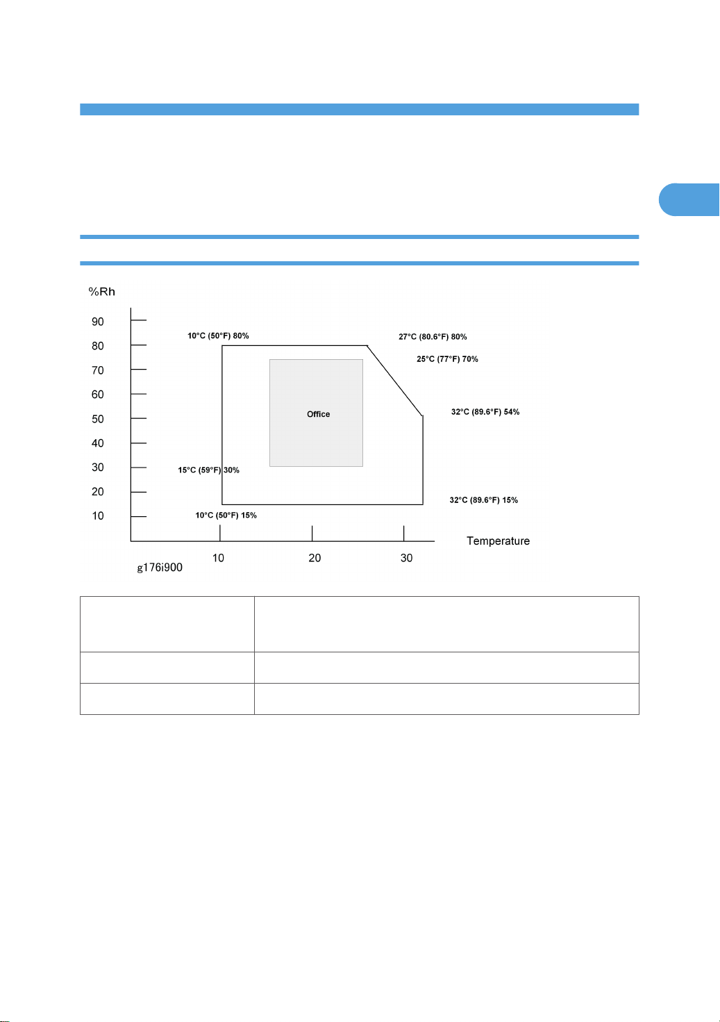
Environment
Temperature/Humidity
Ranges:
Ambient Illumination: Less than 2000 lux (do not expose to direct sunlight).
Ventilation: 3 times/hr/person
1. Avoid areas that are exposed to sudden temperature changes. This includes:
• Areas directly exposed to cool air from an air conditioner.
• Areas directly exposed to heat from a heater.
2. Do not install this machine in an area where it will be exposed to corrosive gases.
3. Do not install the machine at locations over 2,500 m (8,125 ft.) above sea level.
4. Put the machine on a strong and level base. Inclination on any side should not exceed 5 mm.
5. Do not put the machine where it may be subjected to strong vibrations.
Acceptable: 10C (50F) 15% to 27C (80.6F) 80%
Recommended (Office): 15C (59F) 30% to 25C (77F) 70%
11
1. Installation
1
Machine Level
Front to back: Within 5 mm. (0.2 inches) of level.
Right to left: Within 5 mm. (0.2 inches) of level.
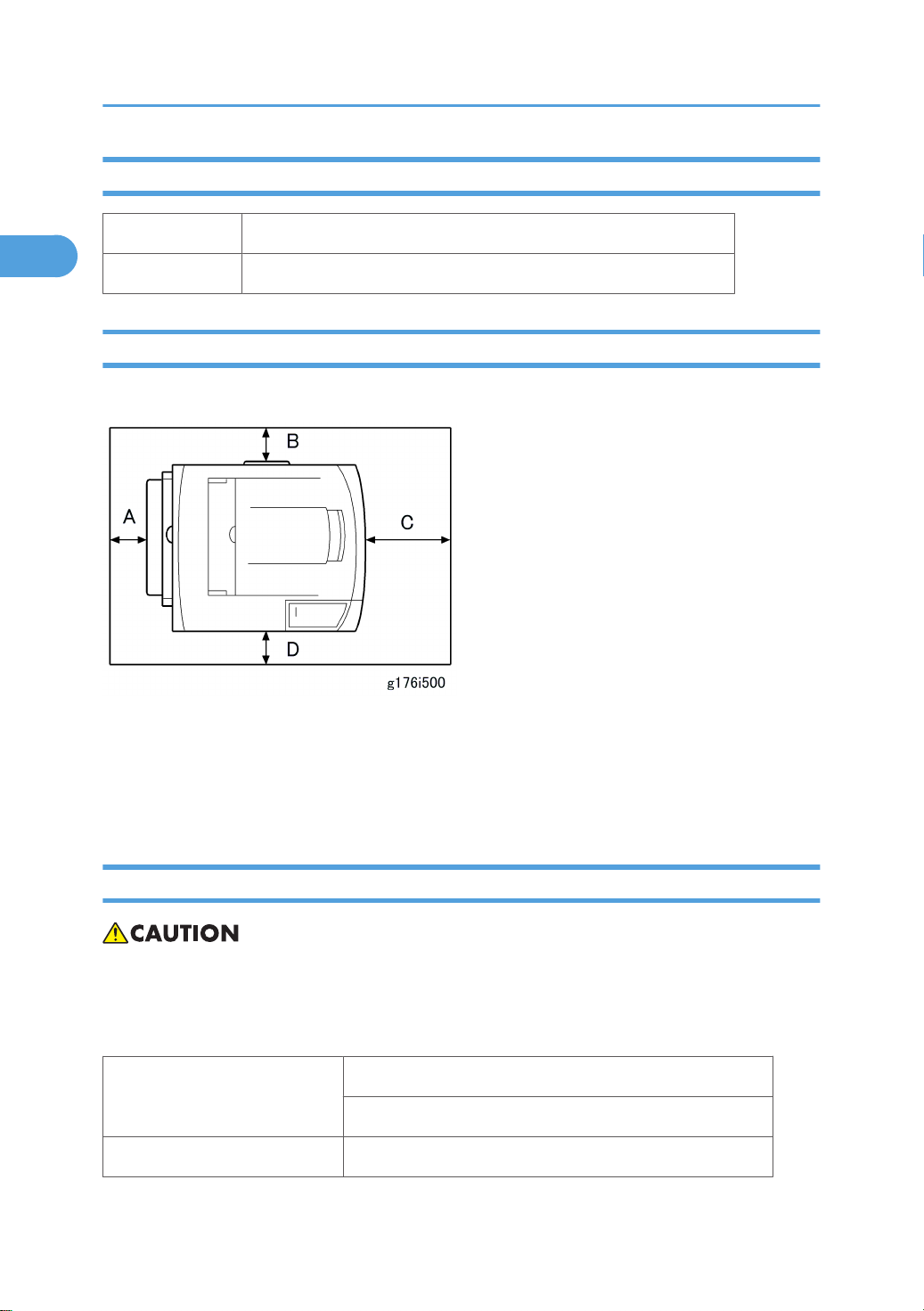
Required Space
Place the machine near the power source, providing the clearance as shown below:
A: Over 10 cm (4 inches)
B: Over 10 cm (4 inches)
C: Over 40 cm (15.8 inches)
D: Over 10 cm (4 inches)
Power Supply
• Make sure the plug is firmly inserted in the outlet.
• Avoid multi-wiring.
• Be sure to ground the machine.
NA: 120 volts, 60 Hz
Input voltage level
EU: 220-240 volts, 50 Hz/60 Hz
Permitted voltage Fluctuation: ±10 %
12

• Never place anything on the power cord.
1
Installation Requirements
13

1. Installation
1
Machine Installation
Refer to the following sections of the “Operating Instructions” for installation details for all models.
Main unit - Quick Installation Guide
Paper Feed Unit G894 Paper Feed Unit TK1030
Envelope Feeder G362 Envelope Feeder Type400
Duplex Unit G893 AD1000 (Duplex Unit)
Memory Unit Type G 128 MB M354
Memory Unit Type G 256 MB D362
Hard Disk Drive Type 2670 M352
IEEE 802.11a/g interface Unit Type L
Options
Drivers - Section 1 of the Software Guide
*1: These units cannot be installed at the same time.
M344 (NA) *1
IEEE 802.11a/g interface Unit Type M M344 (EU)
*1
IEEE 1284 Interface Board Type A B679
Gigabit Ethernet Board Type A G874 *1
VM Card Type K M354
Data Storage Card Type A G874
Data Overwrite Security Unit Type L M352
SD Card for Netware Printing Type B M352 Software Guide, Section 6
Hardware Guide, Section 2
14
Data Overwrite Security Unit Installation
1
Data Overwrite Security Unit Installation
Installation
• The correct number and type for this installation is Type L. Do not attempt to install any other type
(Type C, Type D, for example).
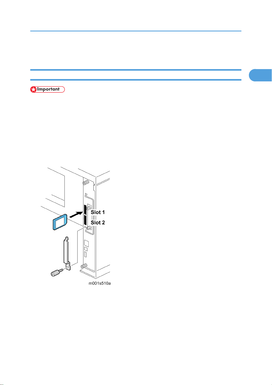
• The SD card that holds the DOS application must always reside in SD card slot 1. (This can be the
original SD or another SD card where the DOS application has been moved with SP5873.)
1. If the machine is on, turn off the main power switch.
2. Disconnect the network cable.
3. Turn the main power switch on.
4. Turn the operation switch and main power switch off.
5. Remove the SD card slot cover (x1).
6. Insert the DOS SD card into Slot 1.
7. Reconnect the network cable, if the network is connected to the copier.
8. Turn the main power switch on.
9. Enter the SP mode and do SP5878 and push [#Enter] to enable the DOS application.
10. Go out of the SP mode, turn the operation switch off, then turn the main power switch off.
15

1. Installation
1
Checking and Completing the Installation
Do this procedure to confirm that the data overwrite security feature is enabled and operating.
1. Turn the machine power on.
2. .Do SP5990 005 (Diagnostic Report) to print the diagnostic report
3. Check the diagnostic report.
• Under [ROM No./Firmware Version] you should see "M3525814" displayed for "HDD Format
Option".
• Under [Loading Program] you should see "GW1a_zoffy: M3525814"
Important
• The numbers in the diagnostic report must match. (The ROM number and firmware version
number change after the firmware has been upgraded.)
• If the ROM numbers or version numbers do not match, this means that the DOS unit type was
incorrect (not "Type L"),
• If this occurs:
(1) Obtain the Type L DOS unit card or confirm that the DOS unit is Type L.
(2) Replace the NVRAM on the controller board.
(3) Insert the Type L DOS unit SD card in Slot 2.
(4) Do the DOS unit installation procedure again.
4. Push and release in this order: [#Enter]> [Escape]> [Menu].
5. Push [] or [] to display "Maintenance" then push [#Enter].
6. Push [] or [] to display "Memory Erase" and "Erase All Mem."
7. If you see "Memory Erase" and "Erase All Mem." in the selections, then the DOS application has been
enabled and is operating.
16

2. Preventive Maintenance
2
User Maintenance
The customer can replace all PM items with the Maintenance Kit.
The user can maintain this machine. For more see "Printer Engine Service Mode".
The operation panel shows “Replace Maintenance Kit” when the PM counter reaches 90K. After the user
replaces the fusing unit in the maintenance kit, the machine automatically resets the PM counter.
Item Quantity Remarks
Fusing unit 1 -
Transfer roller 1 -
Paper feed roller 3 For standard and optional tray(s)
Friction pad 3 For standard and optional tray(s)
17

2. Preventive Maintenance
2
Service Maintenance
To enable the machine for maintenance by the service technician, the meter-charge mode must be set to
“enabled” with SP5930.
The table below shows the PM items serviced by the service technician.
After completing a PM procedure, reset the PM counter for the replaced part with SP7-804.
Symbol key:
• C: Clean
• R: Replace
• L: Lubricate
• I: Inspect
Main unit
Item 90K EM Quantity Remarks
Paper Feed
Paper Feed Roller R C 1 Clean with water
Friction Pad R C 1 Clean with water
Registration Roller C C 1 Clean with water
Bottom Plate Pad C C 1 Clean with water
Around the Drum
Transfer Roller R 1
Fusing Unit and Paper Exit
Hot Roller R 1
Pressure Roller R 1
Hot Roller Strippers R 3
Fusing Thermistor R C 1
Bushings - Hot Roller R 2
Bushings - Pressure Roller R 2
Clean with alcohol if
necessary.
18

Service Maintenance
2
Item 90K EM Quantity Remarks
Fusing Entrance and Exit Guide Plates C 1 each
Fusing Unit Ass'y 110V/220 V R 1
Paper Tray Unit
90K EM Quantity NOTE
Paper Feed Roller R C 1 Clean with water
Friction Pad R C 1 Clean with water
Bottom Plate Pad C C 1 Clean with water
Clean with water or
alcohol
19

2. Preventive Maintenance
2
20

3. Replacement and Adjustment
3
General
Precautions on Disassembly
• Always turn off the main power switch and unplug the machine before attempting any of the
procedures in this section.
Use extreme caution when removing and replacing components. The cables in the machine are located
very close to moving parts; proper routing is a must.
After components have been removed, any cables that have been displaced during the procedure must
be restored as close as possible to their original positions. Before removing any component from the
machine, note any cable routings that may be affected.
Before servicing the machine:
1. Verify that documents are not stored in memory.
2. Remove the print cartridge before you remove parts.
3. Unplug the power cord.
4. Work on a flat and clean surface.
5. Replace with authorized components only.
6. Do not force plastic material components.
Make sure all components are returned to their original positions.
Laser Unit
1. Do not loosen or adjust the screws securing the LD drive board on the LD unit. Doing so will throw the
LD unit out of adjustment.
2. Do not adjust the variable resistors on the LD unit, as these are permanently adjusted at the factory.
If replacement of the LD drive board is necessary, replace the entire LD unit.
3. Keep the polygon mirror and toroidal lens free of dust. Laser performance is very sensitive to dust on
these components.
4. Do not touch the shield glass or the surface of the polygon mirror with bare hands.
5. Do not adjust the Laser Synchronization detector on the LD unit, as these are permanently adjusted
at the factory. If the position of the Laser Synchronization detector has changed from the factory set
position, SC 322 will be shown.
Transfer Roller
1. Never touch the surface of the transfer roller with bare hands.
21

3. Replacement and Adjustment
3
2. Be careful not to scratch the transfer roller, as the surface is easily damaged.
Fusing
1. After installing the fusing thermistor, make sure that it is in contact with the hot roller and that the roller
can rotate freely.
2. Be careful to avoid damage to the hot roller stripper pawls and their tension springs.
3. Do not touch the fusing lamp and rollers with bare hands.
4. Make sure that the fusing lamp is positioned correctly and that it does not touch the inner surface of
the hot roller.
Paper Feed
1. Do not touch the surface of paper feed rollers.
2. To avoid misfeeds, the side and end fences in each paper tray must be positioned correctly so as to
align with loaded paper size.
Releasing Plastic Latches
Many of the parts are held in place with plastic latches. The latches break easily, so release them carefully.
To release a latch, press the hook end of the latch away from the part to which it is latched.
After servicing the machine
1. Make sure all parts that require grounding are properly grounded.
2. Make sure the interlock switch is functioning.
3. Do not leave unused solder or parts inside the machine.
4. Do not leave any tools inside the machine.
22

5. Make sure all wires are properly connected and routed.
3
6. Make sure wires are not jammed between parts of the machine.
General
23

3. Replacement and Adjustment
3
Special Tools
Part No. Description Q’ty Remarks
1 B6455010 SD Card 1 Common
2 B6456700 PCMCIA Card Adapter 1 Common
3 B6456800 USB Reader/Writer 1 Common
4 VSSM9000 Digital Multimeter – FLUKE 187 1 Common
5 A0069104 Scanner Positioning Pin 1 Common
Ricoh System Information Tool (Support
Tool Ver. 2)
6 ---
• Basic version 1
• Mail version 1
24
Covers
3
Upper Cover
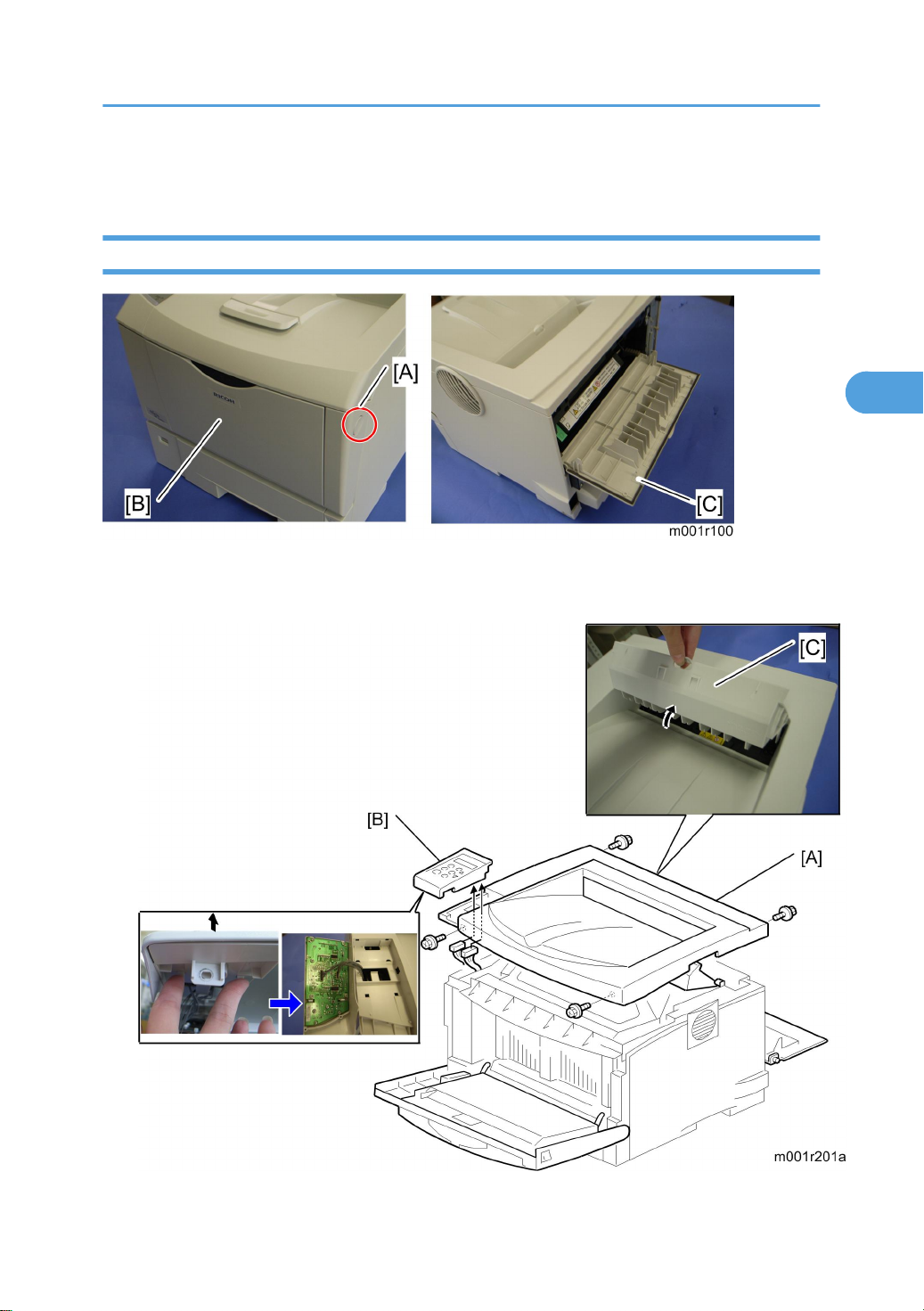
1. Gentry push the front cover release button [A], and open the front cover [B].
2. Open the rear cover [C].
Covers
25

3. Replacement and Adjustment
3
3. Remove four screws of the upper cover [A].
4. Operation panel [B] (2 hooks, x 2)
5. Open the exit guide plate [C], and then remove the upper cover [A].
• Remove the exit guide plate after you have removed the upper cover.
Left Cover
1. Upper cover (* Upper Cover)
1. Left cover [A] ( x 2)
2. Push down the left cover as shown above.
• Make sure that the harness band [A] is placed at clamp [B] the under, when reinstalling the left
cover.
By-Pass Tray Unit
1. Standard paper tray
26
2. By-pass tray unit [A] (hooks x 2)
3
Front Cover
Covers
1. Standard paper tray
2. By-pass tray unit (* By-pass Tray Unit)
3. Upper cover (* Upper Cover)
4. Left cover (* Left Cover)
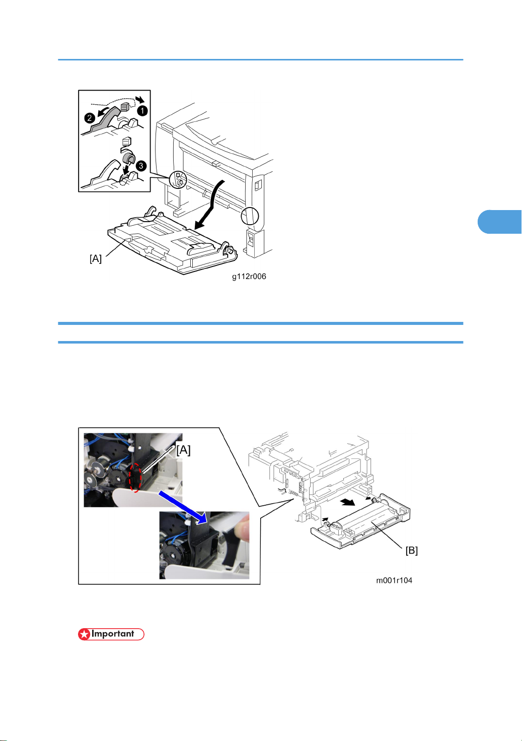
5. Holder [A] (hook)
6. Front cover [B] ( x 3, x 2)
• Remove the by-pass tray unit before removing the front cover.
27
3. Replacement and Adjustment
3
Right Cover
1. Upper cover (* Upper Cover)
2. Left cover (* Left Cover)
3. Front cover (* Front Cover)
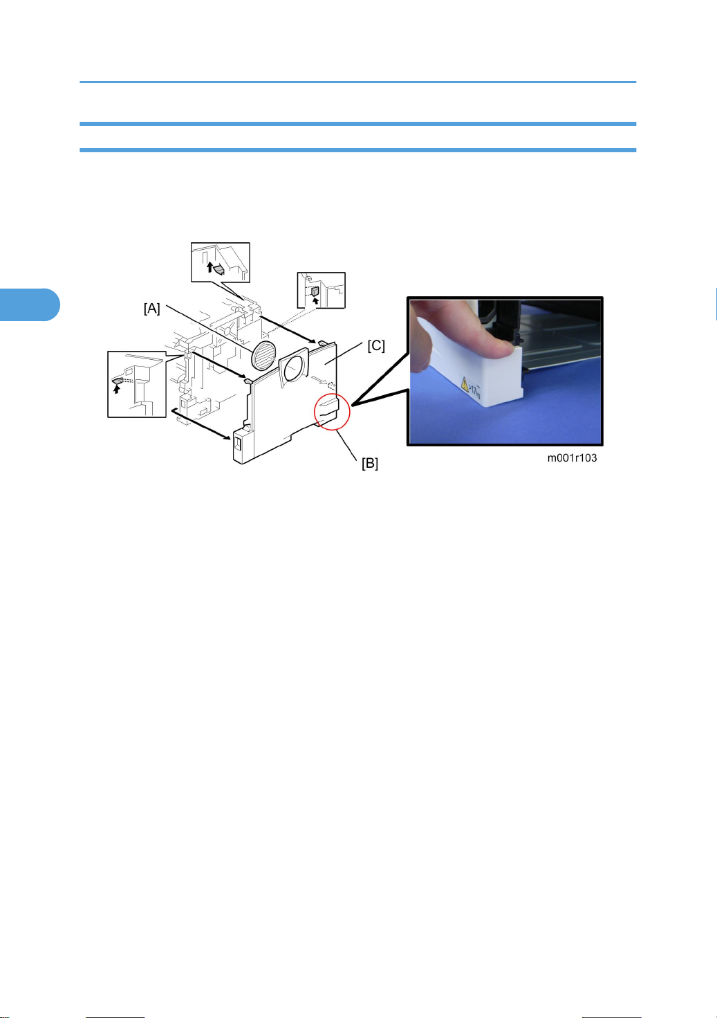
4. Fan cover [A]
5. Release the three hooks, and push down the place [B] as shown above.
6. Right cover [C]
28
 Loading...