

Ricoh S-C3 F, S-C3 SPF Service Manual

Model S-C3 F/SPF MODELS
Machine Code: B284/B288
SERVICE MANUAL
Sep. 29th, 2006
Subject to change

Safety Notice
Important Safety Notices
Prevention of Physical Injury
1. Be sure that the power cord is unplugged before disassembling or assembling parts of the copier or
peripherals.
2. The wall outlet should be near the copier and easily accessible.
3. Note that electrical voltage is supplied to some components of the copier and the paper tray unit even
while the main power switch is off.
4. If any adjustment or operation check has to be made with exterior covers off or open while the main
switch is turned on, keep hands away from electrified or mechanically driven components.
5. If you start a job before the copier completes the warm-up or initializing period, keep hands away
from the mechanical and electrical components until job execution has started. The copier will start
making copies as soon as warm-up or initialization is finished.
6. The inside and the metal parts of the fusing unit become extremely hot while the copier is operating.
Be careful to avoid touching those components with your bare hands.
Health Safety Conditions
Toner and developer are nontoxic, but getting either of these into your eyes may cause temporary eye
discomfort. Try to remove with eye drops or flush with water. If material remains in eye or if discomfort
continues, get medical attention.
Observance of Electrical Safety Standards
The copier and its peripherals must be installed and maintained by a customer service representative who
has completed the training course on those relevant models.
• Keep the machine away from flammable liquids, gases, and aerosols. A fire or an explosion might
occur if this precaution is not observed.
Lithium Batteries
Incorrect replacement of lithium battery(s) on the FCU may pose risk of explosion. Replace only with the
same type or with an equivalent type recommended by the manufacturer. Discard used batteries in
accordance with the manufacturer's instructions.
1

Safe and Ecological Disposal
1. Do not incinerate toner bottles or used toner. Toner dust may ignite suddenly if exposed to an open
flame.
2. Dispose of used toner, developer, and organic photoconductors in accordance with local regulations.
(These are nontoxic supplies.)
3. Dispose of replaced parts in accordance with local regulations.
Laser Safety
The Center for Devices and Radiological Health (CDRH) prohibits the repair of laser-based optical units
in the field. The optical housing unit can only be repaired in a factory or at a location with the requisite
equipment. The laser subsystem is replaceable in the field by a qualified Customer Engineer. The laser
chassis is not repairable in the field. Customer engineers are therefore directed to return all chassis and
laser subsystems to the factory or service depot when replacement of the optical subsystem is required.
• Use of controls not specified in this manual, or performance of adjustments or procedures not specified
in this manual, may result in hazardous radiation exposure.
WARNING FOR LASER UNIT
• Turn off the main switch before attempting any of the procedures in the Laser Unit section. Laser
beams can seriously damage your eyes.
CAUTION MARKING:
2
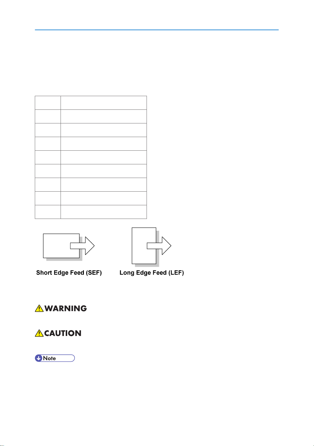
Symbols and Abbreviations
This manual uses several symbols and abbreviations. The meaning of those symbols and abbreviations is
as follows:
* See or Refer to
Clip ring
E-ring
Screw
Connector
Clamp
SEF Short Edge Feed
LEF Long Edge Feed
Core Technology manual
Cautions, Notes, etc.
The following headings provide special information:
• FAILURE TO OBEY WARNING INFORMATION COULD RESULT IN SERIOUS INJURY OR DEATH.
• Obey these guidelines to ensure safe operation and prevent minor injuries.
• This information provides tips and advice about how to best service the machine.
3

TABLE OF CONTENTS
Safety Notice......................................................................................................................................................1
Important Safety Notices..........................................................................................................................1
Laser Safety.....................................................................................................................................................2
Symbols and Abbreviations...............................................................................................................................3
1. Installation
Installation Cautions.........................................................................................................................................11
Installation Requirements.................................................................................................................................12
Environment..................................................................................................................................................12
Machine Level..............................................................................................................................................12
Minimum Operational Space Requirements.............................................................................................13
Power Requirements....................................................................................................................................14
Copier...............................................................................................................................................................15
Accessory Check..........................................................................................................................................15
Installation Procedure..................................................................................................................................15
Optional Hand Set.......................................................................................................................................22
Paper Tray Unit.................................................................................................................................................25
Accessory Check..........................................................................................................................................25
Installation Procedure..................................................................................................................................25
Paper Tray Unit Heater....................................................................................................................................27
Accessory Check..........................................................................................................................................27
Installation Procedure..................................................................................................................................28
Controller Options............................................................................................................................................35
Overview......................................................................................................................................................35
PostScript3 Installation................................................................................................................................36
Wireless LAN (IEEE 802.11b) Installation................................................................................................36
IEEE 1284 Installation.................................................................................................................................38
Bluetooth Installation...................................................................................................................................39
2. Preventive Maintenance
PM Tables.........................................................................................................................................................41
How to Clear the PM Counter.........................................................................................................................43
3. Replacement and Adjustment
Precautions........................................................................................................................................................45
General.........................................................................................................................................................45
4

Lithium Batteries............................................................................................................................................45
Halogen-free Cable....................................................................................................................................45
Special Tools and Lubricants...........................................................................................................................46
Exterior Covers and Operation Panel............................................................................................................47
Rear Cover...................................................................................................................................................47
Copy Tray.....................................................................................................................................................47
Operation Panel and Upper Covers..........................................................................................................48
Right Door.....................................................................................................................................................49
Bypass Tray..................................................................................................................................................50
Platen Cover Sensor....................................................................................................................................50
Scanner Unit.....................................................................................................................................................51
Exposure Glass............................................................................................................................................51
Lens Block.....................................................................................................................................................51
Exposure Lamp, Lamp Stabilizer Board.....................................................................................................52
Scanner Motor.............................................................................................................................................53
Scanner HP Sensor......................................................................................................................................54
Scanner alignment adjustment....................................................................................................................55
Fusing................................................................................................................................................................57
Fusing Unit....................................................................................................................................................57
Exit Sensor....................................................................................................................................................58
Hot Roller Stripper Pawls.............................................................................................................................58
Hot Roller and Fusing Lamp........................................................................................................................59
Thermoswitches and Thermistor..................................................................................................................61
Pressure Roller..............................................................................................................................................62
Checking the NIP band...............................................................................................................................63
PCU and Quenching Lamp.............................................................................................................................64
PCU...............................................................................................................................................................64
Quenching Lamp..........................................................................................................................................65
Exhaust Fan and Main Motor.........................................................................................................................66
Exhaust Fan..................................................................................................................................................66
Main Motor..................................................................................................................................................67
Paper Feed........................................................................................................................................................68
Paper Feed Roller and Friction Pad............................................................................................................68
5

Paper End Sensor.........................................................................................................................................69
Registration Sensor......................................................................................................................................69
Bypass Paper End Sensor...........................................................................................................................70
Bypass Feed Roller......................................................................................................................................71
Bypass Feed Clutch and Friction Pad.........................................................................................................72
Paper Feed and Registration Clutches.......................................................................................................73
Image Transfer..................................................................................................................................................75
Transfer Roller..............................................................................................................................................75
ID Sensor and Duplex Roller.......................................................................................................................76
Discharge plate............................................................................................................................................77
BICU and Controller Board.............................................................................................................................78
BICU..............................................................................................................................................................78
Controller Board..........................................................................................................................................79
Other Replacements.........................................................................................................................................83
Duplex Motor...............................................................................................................................................83
High-Voltage Power Supply Board ...........................................................................................................84
PSU Assembly..............................................................................................................................................85
PSU................................................................................................................................................................85
Contact-Release Solenoid...........................................................................................................................86
Toner Supply Clutch....................................................................................................................................87
FCU...............................................................................................................................................................87
Laser Unit..........................................................................................................................................................89
Location of the Caution Decal....................................................................................................................89
Laser Unit......................................................................................................................................................89
LD Unit and Polygon Mirror Motor............................................................................................................90
ARDF ................................................................................................................................................................91
ARDF.............................................................................................................................................................91
DF Rear Cover..............................................................................................................................................92
Original Feed Unit.......................................................................................................................................92
Separation Roller.........................................................................................................................................93
DF Drive Board............................................................................................................................................93
Original Set and DF Inverter Sensor..........................................................................................................94
DF Registration and DF Exit Sensor............................................................................................................95
6

DF Feed Motor.............................................................................................................................................96
DF Transport Motor.....................................................................................................................................97
DF Feed Clutch.............................................................................................................................................98
Adjusting Copy Image Area............................................................................................................................99
Printing..........................................................................................................................................................99
Scanning....................................................................................................................................................101
DF Image Adjustment................................................................................................................................104
4. Troubleshooting
Service Call Conditions.................................................................................................................................107
Summary....................................................................................................................................................107
Engine SC Code Descriptions..................................................................................................................107
GW SC Code Descriptions......................................................................................................................116
Electrical Component Troubleshooting........................................................................................................129
Sensor/Switch Open Errors.....................................................................................................................129
Blown Fuse Conditions..............................................................................................................................130
BICU LED Display......................................................................................................................................131
5. Service Tables
Service Program.............................................................................................................................................133
Using SP and SSP Modes.........................................................................................................................133
Copier Service Program Mode Tables....................................................................................................134
ID Sensor Error Analysis (SP2-221)........................................................................................................218
Memory Clear...........................................................................................................................................218
Input Check (SP5-803).............................................................................................................................220
Output Check (SP5-804).........................................................................................................................221
Machine No. Setting (SP5-811-001).....................................................................................................223
NVRAM Data Upload/Download..........................................................................................................223
Firmware Update Procedure....................................................................................................................225
Test Pattern Print (SP5-902-001).............................................................................................................230
SMC Print (SP5-990)................................................................................................................................233
Power-on Self Test.....................................................................................................................................233
Printer Service Mode.................................................................................................................................234
Scanner Program Mode Table.................................................................................................................234
6. Detailed Section Descriptions
7

Overview........................................................................................................................................................237
Component Layout....................................................................................................................................237
Electrical Components..............................................................................................................................239
Paper Path......................................................................................................................................................242
Drive Layout...................................................................................................................................................243
Mainframe.................................................................................................................................................243
ARDF...........................................................................................................................................................244
Block Diagram: PCBs and Components......................................................................................................245
Main PCBs......................................................................................................................................................246
SBU (Sensor Board Unit)..........................................................................................................................246
Copy Process.................................................................................................................................................248
Overview....................................................................................................................................................248
Scanning.........................................................................................................................................................250
Overview....................................................................................................................................................250
Scanner Drive............................................................................................................................................251
Image Processing...........................................................................................................................................252
Overview....................................................................................................................................................252
Image Processing Path..............................................................................................................................253
Original Modes.........................................................................................................................................253
Image Processing Steps for Each Mode..................................................................................................256
Mode Adjustments.....................................................................................................................................257
Laser Exposure...............................................................................................................................................258
Overview....................................................................................................................................................258
LD Safety Switches....................................................................................................................................259
Photoconductor Unit (PCU)...........................................................................................................................260
Overview....................................................................................................................................................260
Drum Drive.................................................................................................................................................261
Drum Charge.................................................................................................................................................262
Overview....................................................................................................................................................262
Charge Roller Voltage Correction...........................................................................................................263
Charge Roller Cleaning............................................................................................................................264
Detection of New PCU..............................................................................................................................264
Development..................................................................................................................................................266
8

Overview....................................................................................................................................................266
Development Bias......................................................................................................................................267
Toner Supply..............................................................................................................................................267
Toner Density Control................................................................................................................................268
Toner Supply If Sensor Reading is abnormal .........................................................................................269
Detection of Toner Near End and Toner End .........................................................................................270
Drum Cleaning and Toner Recycling...........................................................................................................271
ARDF Operation............................................................................................................................................272
Pick-Up and Separation............................................................................................................................272
Clutch Operation.......................................................................................................................................272
Original Transport and Exit......................................................................................................................272
Paper Feed.....................................................................................................................................................275
Overview....................................................................................................................................................275
Paper Feed Drive Mechanism..................................................................................................................276
Paper Feed and Separation.....................................................................................................................278
Paper Lift Mechanism................................................................................................................................278
Paper End Detection..................................................................................................................................279
Image Transfer and Paper Separation.........................................................................................................281
Overview....................................................................................................................................................281
Image Transfer Current Timing.................................................................................................................281
Transfer Roller Cleaning...........................................................................................................................282
Image Fusing and Paper Exit........................................................................................................................283
Overview....................................................................................................................................................283
Hot Roller Drive.........................................................................................................................................284
Pressure Roller............................................................................................................................................285
Pressure Release........................................................................................................................................285
Separation.................................................................................................................................................286
Fusing Temperature Control.....................................................................................................................286
Duplex Unit.....................................................................................................................................................290
Important Components.............................................................................................................................290
Duplex Printing Process.............................................................................................................................291
Energy Saver Modes.....................................................................................................................................295
Overview....................................................................................................................................................295
9

AOF............................................................................................................................................................296
Timers.........................................................................................................................................................296
Recovery....................................................................................................................................................296
GW Controller...............................................................................................................................................297
Overview....................................................................................................................................................297
Controller Functions...................................................................................................................................298
Scanner Functions.....................................................................................................................................300
7. Specifications
General Specifications..................................................................................................................................303
Copier........................................................................................................................................................303
Printer..........................................................................................................................................................305
Scanner......................................................................................................................................................306
ARDF...........................................................................................................................................................307
Paper Tray Unit..........................................................................................................................................308
Supported Paper Sizes..................................................................................................................................309
Original Paper Sizes.................................................................................................................................309
Paper Feed.................................................................................................................................................310
Machine Configuration.................................................................................................................................313
Mainframe (B284/B288)........................................................................................................................313
System Components..................................................................................................................................314
10

1. Installation
1
Installation Cautions
• Before installing an optional unit, do the following:
• Print out all messages stored in the memory, all user-programmed items, and a system parameter
list.
• If there is a printer option on the machine, print out all data in the printer buffer.
• Turn off the main switch and disconnect the power cord, the telephone line, and the network
cable.
11
1. Installation
1
Installation Requirements
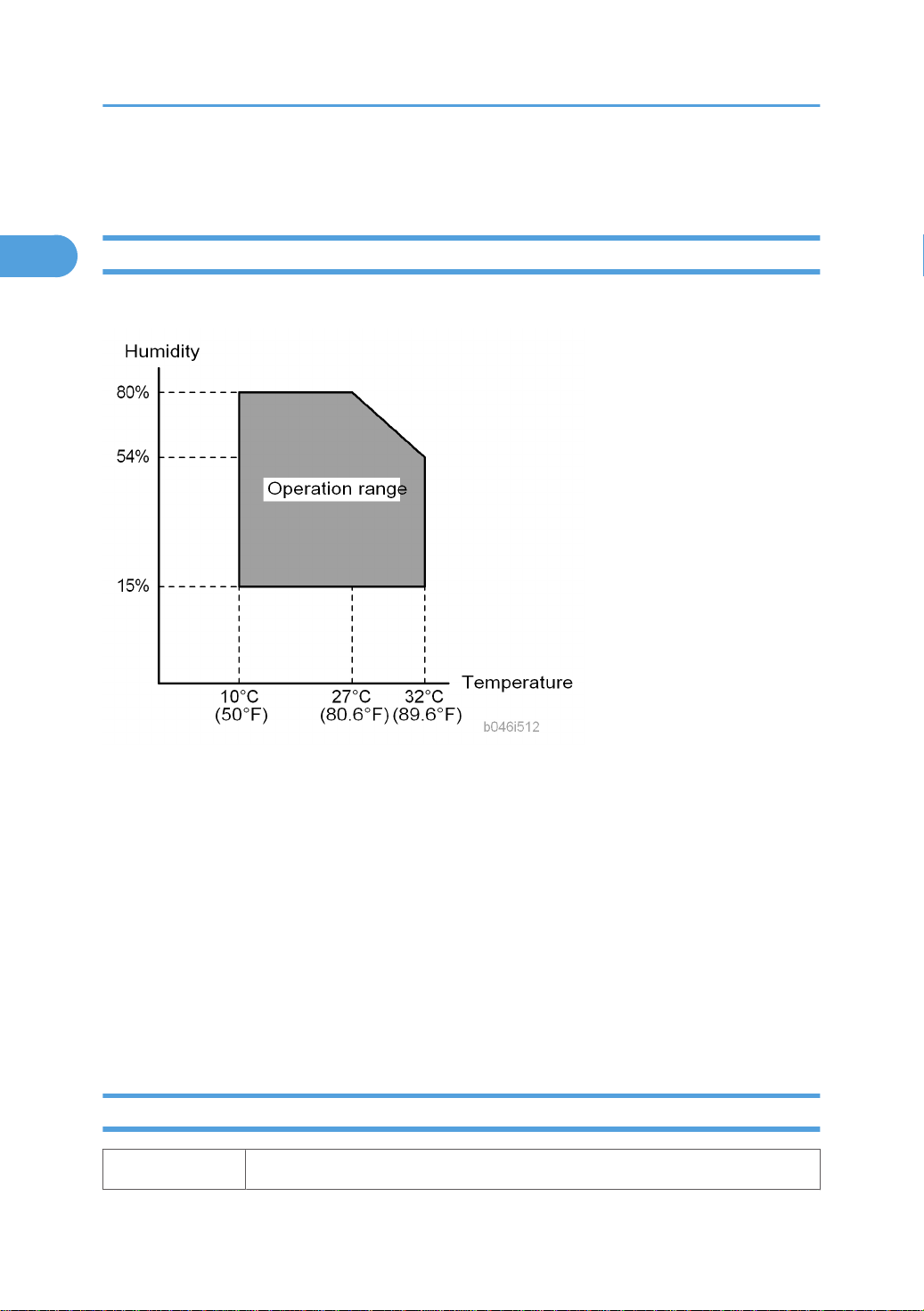
Environment
–Temperature and Humidity Chart–
• Temperature Range: 10°C to 32°C (50°F to 89.6°F)
• Humidity Range: 15% to 80% RH
• Ambient Illumination: Less than 1,500 lux (Do not expose to direct sunlight.)
• Ventilation: Room air should turn over at least 3 times/hr/person
• Ambient Dust: Less than 0.1 mg/m
• Do not install the machine where it will be exposed to direct sunlight or to direct airflow (from a fan,
• Do not install the machine where it will be exposed to corrosive gas.
• Place the machine on a firm and level base.
• Do not install the machine where it may be subjected to strong vibration.
Machine Level
Front to back: Within 5 mm (0.2") of level
12
3
air conditioner, air cleaner, etc.).
Right to left: Within 5 mm (0.2") of level
1
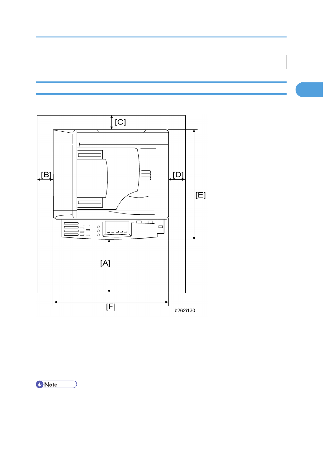
Minimum Operational Space Requirements
Place the machine near the power source, providing clearance as shown.
Installation Requirements
A: Front – 750 mm (29.6")
B: Left – 100 mm (3.9")
C: Rear – 105 mm (4.1")
D: Right – 230 mm (9.0")
E: Depth – 450 mm (17.7")
F: Width – 485 mm (19.1")
• The 750-mm front space indicated above is sufficient to allow the paper tray to be pulled out.
Additional space is required to allow an operator to stand at the front of the machine.
13

1. Installation
1
• Actual minimum space requirement for left, rear, and right sides is 10mm (0.4") each, but note that
this will not allow room for opening of the bypass tray, right door, platen cover, or ARDF unit.
Power Requirements
• Make sure that the wall outlet is near the machine and easily accessible. After completing installation,
make sure the plug fits firmly into the outlet.
• Avoid multiple connections to the same power outlet.
• Be sure to ground the machine.
Input voltage:
North America: 110 – 120 V, 60 Hz, 8 A
Europe: 220 – 240 V, 50/60 Hz, 4 A
Image quality guaranteed at rated voltage ± 10%.
Operation guaranteed at rated voltage ± 15%.
14

Copier
1
Accessory Check
Fax Model (B284)/ Printer/Scanner and Fax Model (B288)
Description Q’ty
NECR (-17) 1
EU Safety Sheet (-67, -26) 1
Paper Size Decal 1
Model Name Plate - RIC,LAN, GES,INF (-29) 1 set
Handset Bracket (-17) 1
Copier
Screw for Handset Bracket (-17) 2
Modular Cable (-17) 1
Connecter Cover for TEL (-17) 1
User Function Key Decal (-17, -29 1
Ferrite Core for TEL Line 1
Operating Instructions - Book (-17, -29) 1 set
Operating Instructions – CD ROM (-17, -29) 1 set
Installation Procedure
• Make sure that the copier remains unplugged during installation.
15
1. Installation
1
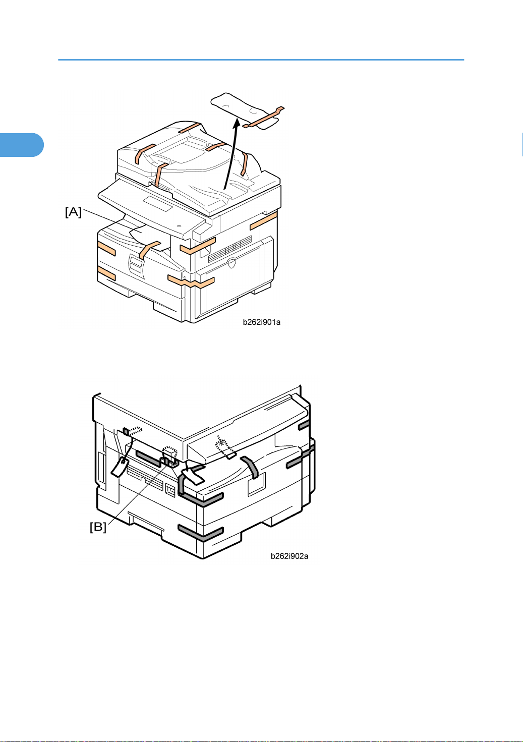
1. Remove the all strips of tape.
2. Remove the bag [A], SMC and A3 sheet of paper on the exposure glass.
3. Remove the spacing wedge [B].
16
Copier
1
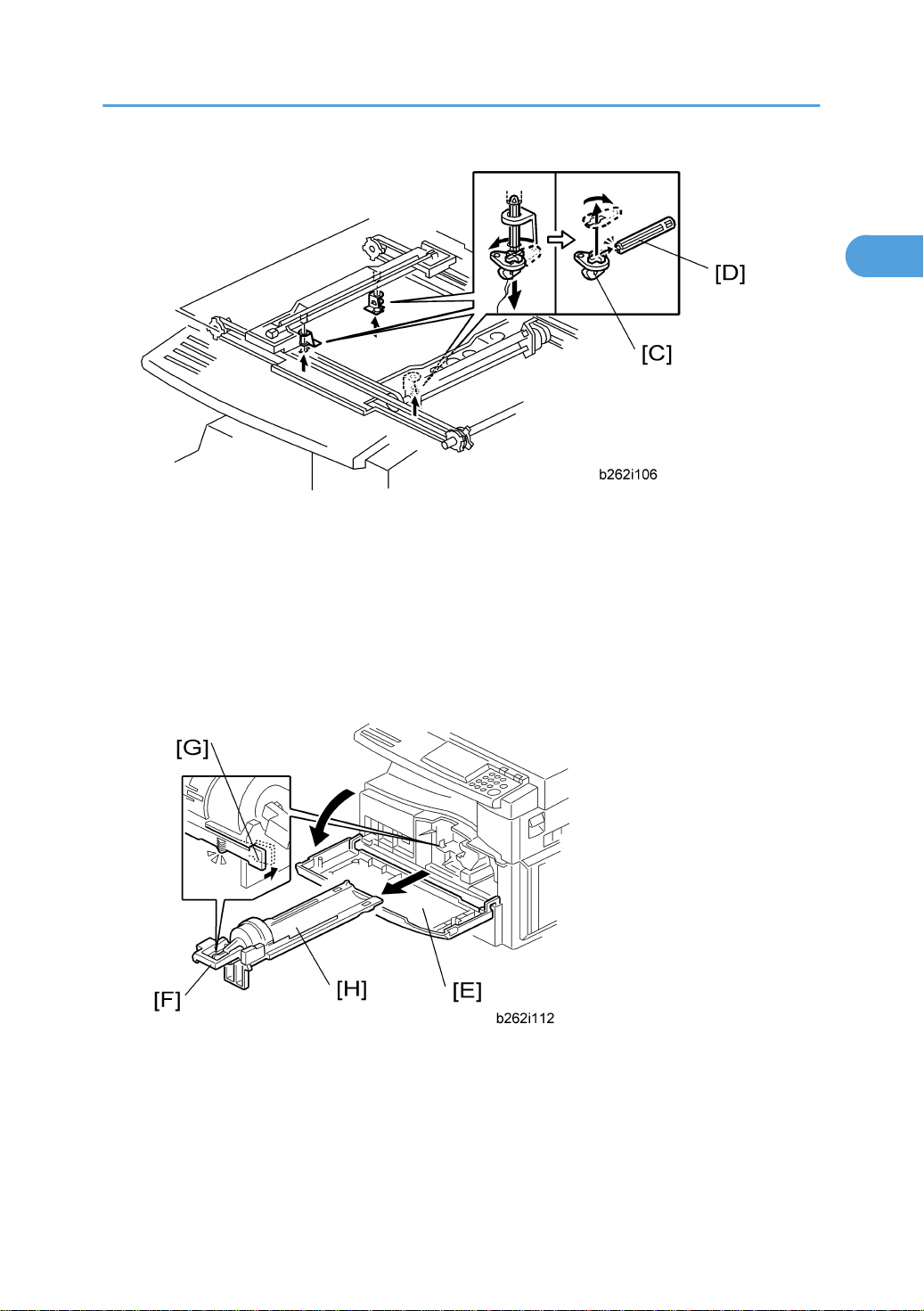
4. Remove the three scanner lock pins. (A tag is hanging from each pin.) To remove: Grasp the base of
the pin [C], turn the pin 90 degrees, and pull it down and out.
5. Remove the tags from the pins.
6. Break each pin off the base [C].
7. Discard the pin part [D].
8. Set each base [C] back into its original hole, turning it 90° to lock it into place. (Be sure to do this for
all three pins.)
9. Open the front door [E].
10. Lift lever [F], press in on latch [G] and pull the bottle holder [H] out. (You do not need to pull it completely
out of the machine.)
11. Take a new bottle of toner, and shake it several times.
17
1. Installation
1
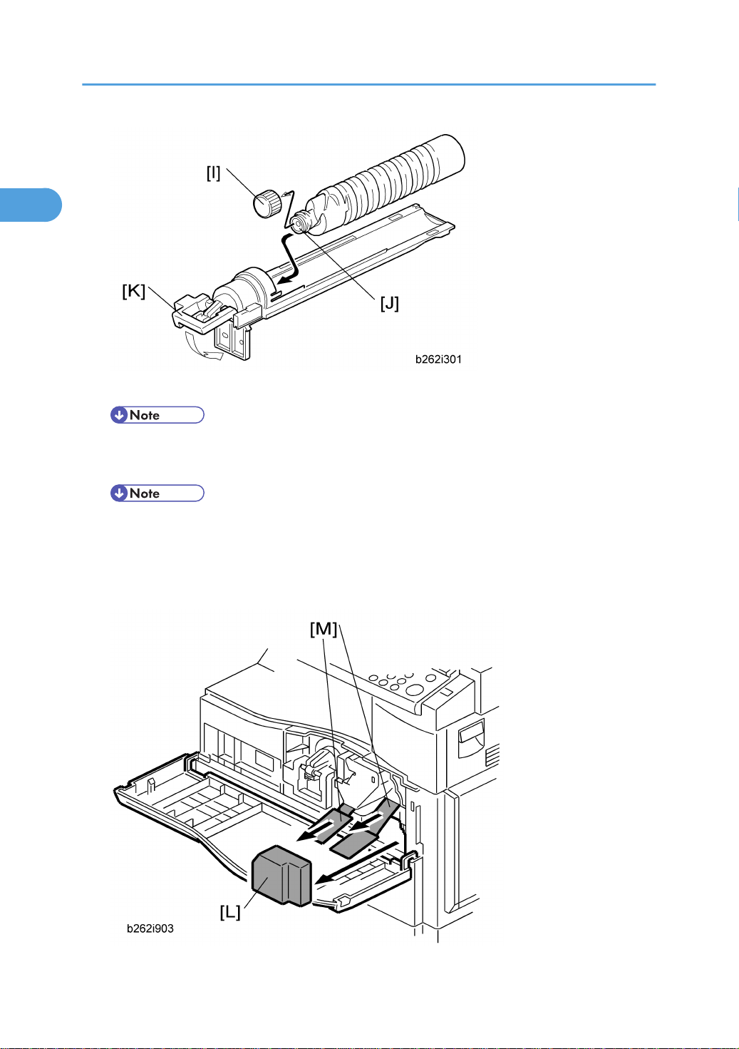
12. Remove the outer cap [I].
• Do not remove the inner cap [J].
13. Load the bottle on the holder.
• Do not forcefully turn the toner bottle on the holder. After you turn on the main power switch, the
copier sets the bottle in place.
14. Push the bottle holder back into the machine.
15. Press the latch [K] down to lock the holder.
18
16. Remove the padding [L].
1
17. Pull each tabbed strip [M] out of the PCU with one hand, supporting the PCU with the other.
• Do not pull both strips at the same time, as this could damage the PCU.
18. Close the front door.
Copier
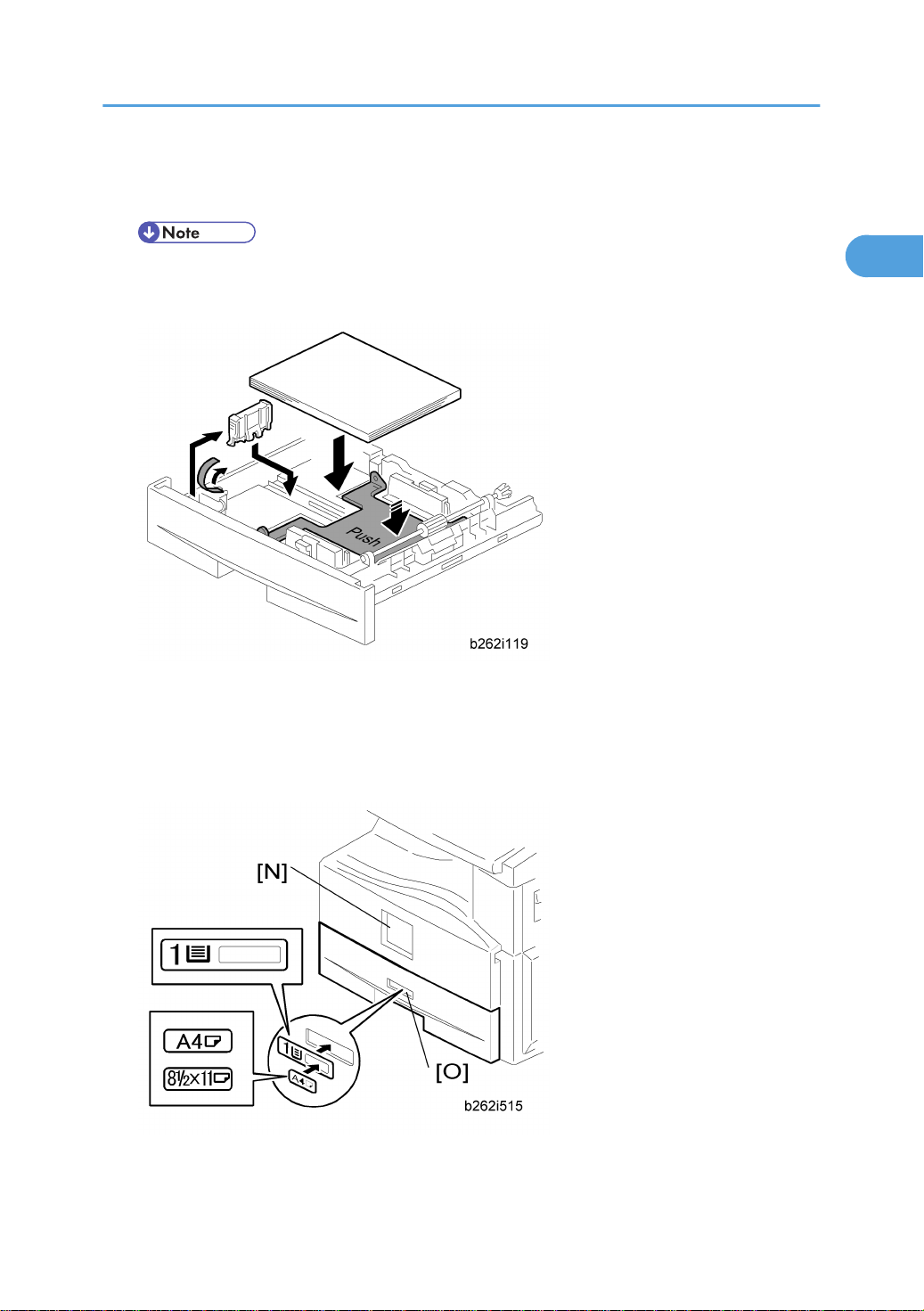
19. Pull out the paper tray, and remove the tape securing the end fence in the compartment.
20. Push the bottom plate down, and then load the paper.
21. Adjust the side fences. If you load paper shorter than A4, set the end fence in the correct position.
22. Push the tray back into the copier.
23. Attach the appropriate Brand Decal to the center [N] of the front door if necessary.
24. Attach the appropriate tray number decal and paper-size decal to the paper tray [O].
19

1. Installation
1
25. Install optional units (if any).
26. Attach the ferrite core [P] to the network cable when connecting the cable.
27. Attach the ferrite core to the telephone line as same manner step 26.
28. Connect the telephone line to the "LINE" jack.
• The end of the ferrite core must be about 10 cm (4") from the end [Q] of the cable.
29. Plug in the machine and turn on the main power switch.
30. Select the language used in the operation panel as necessary ( > Language).
Interface settings
For B284
1. Start the SP mode.
2. Select SP5-985-001 (NIC setting) and change the setting value to "0" (OFF).
3. Select SP5-985-002 (USB setting) and change the setting value to "0" (OFF).
4. Turn the main switch off and on.
For B288
1. Start the SP mode.
2. Select SP5-985-001 (NIC setting) and change the setting value to "1" (ON).
3. Select SP5-985-002 (USB setting) and change the setting value to "1" (ON).
4. Turn the main switch off and on.
20

Copier settings
1
1. Start the SP mode.
2. Select SP5-801-001 and execute the initialization.
3. Exit the SP mode, and then start the UP mode.
4. Select the "@Remote Service" ("User Tool" > "System Settings > Administrator Tools" > "Extended
Security" > @Remote Service") and select "Prohibit".
5. Exit the UP mode, and then start the SP mode.
6. Select SP5-870-003 and execute initialization for @Remote.
7. Select SP5-907-001 and specify the "Plug & Play".
8. Select SP5-870-001 and execute writing certification for @Remote S.
9. Select SP5-302-002 and specify the time zone.
10. Select SP5-307-001, 003, and 004 and specify the daylight-saving-time settings.
11. Exit the SP mode and turn the main switch off and on.
12. Start the UP mode.
Copier
13. Specify the date and time with "Set Date" or "Set Time" (User Tool" > "System Settings" > "Set Date"
or "Set Time").
14. Turn the main switch off and on.
15. Check the operations.
16. Make a full size copy, and check if the side-to-side and leading edge registrations are correct. If they
are not, adjust the registrations.
Fax Settings
Initializing the Fax unit
When you press the Fax key for the first time after installation, the error "SRAM problem occurred / SRAM
was formatted" will show on the LCD for initializing the program of the fax unit. Turn the main power switch
off/on to clear the error display.
• If another error occurs after initialization, this can be a functional problem.
1. Select fax SP1-101-016 and specify the country code.
2. Select fax SP3-101-001 and specify the service station.
21
1. Installation
1
Optional Hand Set
Accessory Check
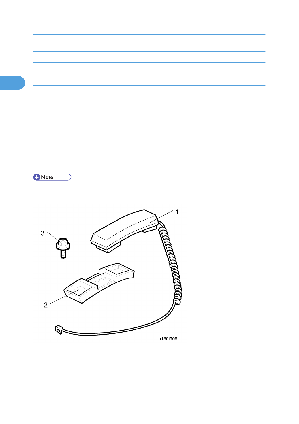
Check that you have the components and accessories.
No. Description Q’ty
1 Handset 1
2 Handset cradle 1
3 Screws 2
4 Handset manual 1
• The handset bracket is not included in the optional handset kit. The bracket is provided as an accessory
of the copier.
22
Installation Procedure
1
Copier
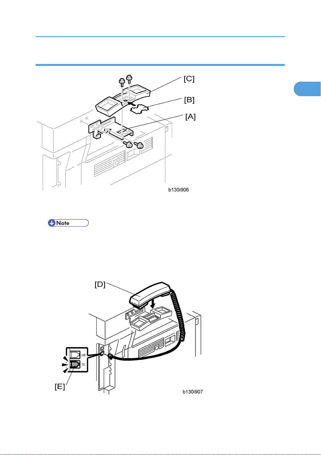
1. Attach the handset bracket [A] ( x 2).
• The bracket is an accessory of the copier.
2. Remove the label [B] from the handset cradle [C].
3. Attach the cradle to the bracket ( x 2).
4. Reattach the label.
5. Set the handset [D] on the cradle.
23

1. Installation
1
6. Connect the cable [E] to the TEL jack at the left side of the copier.
24

Paper Tray Unit
1
Accessory Check
Confirm that you have these accessories.
Description Q’ty
1. Paper-size decals 1 sheet
2. Installation Procedure (for service person) 1
3. Installation Procedure (for user) 1
Installation Procedure
Paper Tray Unit
• Unplug the main machine's power cord before starting the following procedure.
1. Remove the tape at [A], and the tape and cardboard at [B].
2. Pull the paper tray part way out of the unit, remove the tape and cardboard at [C], and push the tray
back in.
25
1. Installation
1
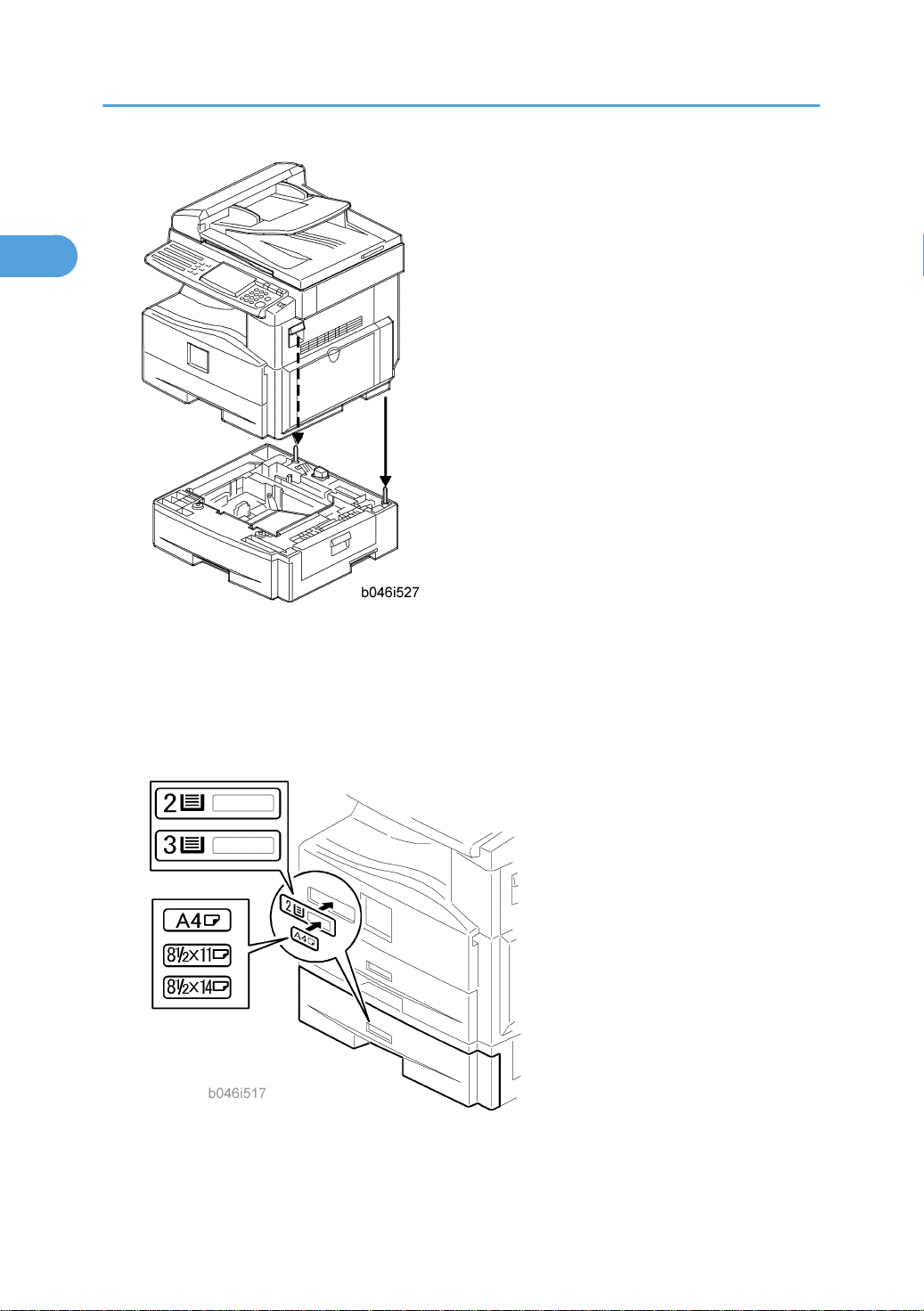
3. Set the machine on the paper tray unit.
4. Remove the paper tray from the paper tray unit.
5. Load paper into the paper tray. Adjust the side and end fences as necessary. If loading 81/2"x 14"
paper, remove the end fence and set it into the special compartment.
6. Set the paper tray back into the paper tray unit.
7. Stick on the appropriate tray-number decal and paper-size decal, at the locations indicated in the
illustration.
26

Paper Tray Unit Heater
1
Accessory Check
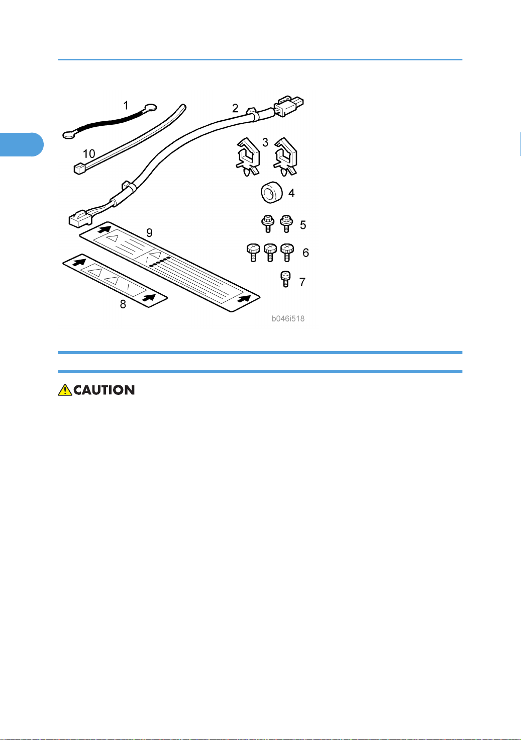
Confirm that you have the accessories listed below.
Description Q’ty
1. Grounding wire 1
2. Relay harness 1
3. Clamps 2
4. Ferrite core 1
5. Heater fastening screws 2
6. PTU fastening screws 3
Paper Tray Unit Heater
7. Grounding screw 1
8. Decal for copier 1
9. Decal for paper unit 1
10. Tie wrap 1
27
1. Installation
1
Installation Procedure
• Unplug the main machine's power cord before starting the following procedure.
1. Remove the paper tray unit from the copier if it is already installed.
2. Remove the paper trays from the copier and from the paper tray unit.
28

Paper Tray Unit Heater
1
3. Remove the ground screw [1] at the rear of the paper tray unit.
4. Fasten the heater [2] and the supplied ground wire [3] to the paper tray unit ( x 3). Note that [1] is
the ground screw you removed in the previous step and [4] and [5] are the two supplied heater
fastening screws.
• Be sure to position the ground wire [3] and heater harness [6] so that they are out of the way of
the copier when you set it onto the paper tray unit.
5. Set the copier onto the paper tray unit.
6. Screw the paper tray unit into place using three supplied PTU fastening screws.
29
 Loading...