

Page 1
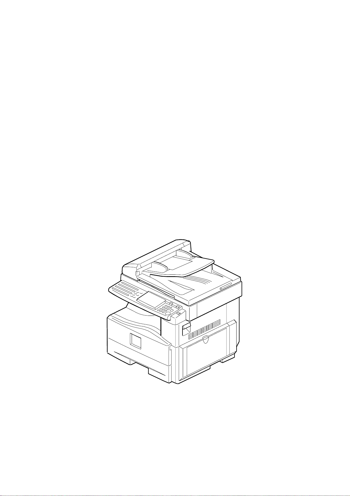
Model S-C1
(Machine Code: B045/B049/B044/B046)
SERVICE MANUAL
B046I100.WMF
17 July, 2001
Subject to change
Page 2

!
IMPORTANT SAFETY NOTICES
PREVENTION OF PHYSICAL INJURY
1. Be sure that the power cord is unplugged before disassembling or
assembling parts of the copier or peripherals.
2. The wall outlet should be near the copier and easily accessible.
3. Note that electrical voltage is supplied to some components of the copier
and the paper tray unit even while the main power switch is off.
4. If you start a job before the copier completes the warm-up or initializing
period, keep hands away from the mechanical and electrical components
until job execution has started. The copier will start making copies as soon
as warm-up or initialization is finished.
5. The inside and the metal parts of the fusing unit become extremely hot while
the copier is operating. Be careful to avoid touching those components with
your bare hands.
HEALTH SAFETY CONDITIONS
Toner and developer are nontoxic, but getting either of these into your eyes may
cause temporary eye discomfort. Try to remove with eye drops or flush with
water. If material remains in eye or if discomfort continues, get medical attention.
OBSERVANCE OF ELECTRICAL SAFETY STANDARDS
The copier and its peripherals must be installed and maintained by a customer
service representative who has completed the training course on those relevant
models.
LITHIUM BATTERIES
Incorrect replacement of lithium battery(s) on the FCU may pose risk of
explosion. Replace only with the same type or with an equivalent type
recommended by the manufacturer. Discard used batteries in accordance with
the manufacturer’s instructi ons.
SAFE AND ECOLOGICAL DISPOSAL
1. Do not incinerate toner bottles or used toner. Toner dust may ignite suddenly
if exposed to an open flame.
2. Dispose of used toner, developer, and organic photoconductors in
accordance with local regulations. (These are nontoxic supplies.)
3. Dispose of replaced parts in accordance with local regulations.
1
Page 3
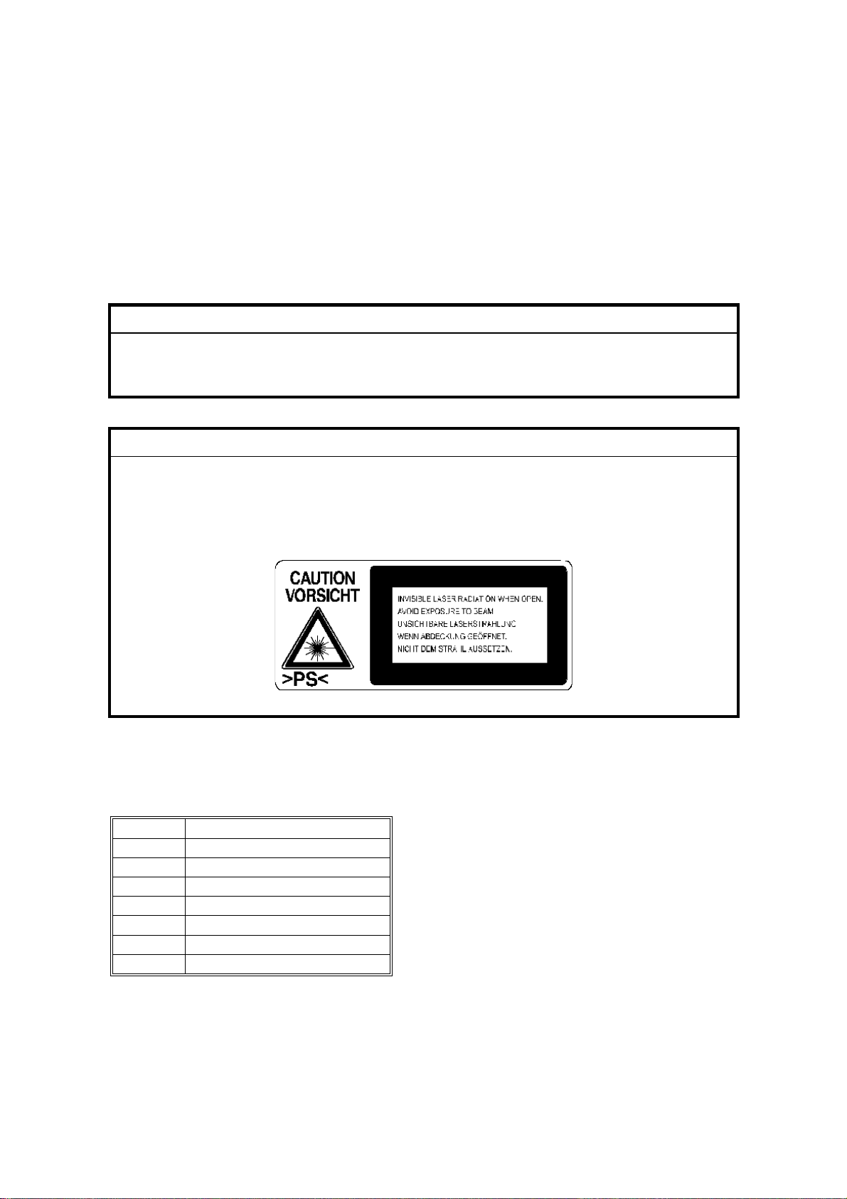
LASER SAFETY
The Center for Devices and Radiological Health (CDRH) prohibits the repair of
laser-based optical units in the field. The optical housing unit can only be repaired
in a factory or at a location with the requisite equipment. The laser subsystem is
replaceable in the field by a qualified Customer Engineer. The laser chassis is not
repairable in the field. Customer engineers are therefore directed to return all
chassis and laser subsystems to the factory or service depot when replacement of
the optical subsystem is required.
!
WARNING
Use of controls not specified in this manual, or performance of
adjustments or procedures not specified in this manual, may result in
hazardous radiation exposure.
!
WARNING FOR LASER UNIT
WARNING: Turn off the main switch before atte mpting any of the
procedures in the Laser Unit section. Laser beams can cause
serious damage to eyes.
CAUTION MARKING:
Symbols and Abbreviations
This manual uses the symbols and abbrev i ati ons show n below.
Symbol Meaning
☛
!
"
#
SEF Short Edge Feed
LEF Long Edge Feed
$
"See," "Refer to"
Clip ring
Screw
Connector
Core Technology manual
2
Page 4

TABLE OF CONTENTS
1 INSTALLATION ........................................................................... 1-1
1.1 INSTALLATION REQUIREMENTS ...........................................................1-1
1.1.1 ENVIRONMENT ...............................................................................1-1
1.1.2 MACHINE LEVEL.............................................................................1-2
1.1.3 MINIMUM OPERATIONAL SPACE REQUIREMENTS ....................1-2
1.1.4 POWER REQUIREMENTS ..............................................................1-3
1.2 COPIER.....................................................................................................1-4
1.2.1 ACCESSORY CHECK......................................................................1-4
1.2.2 INSTALLATION PROCEDURE ........................................................1-4
Initial Programming: Faxless models (B044, B045) .............................1-8
Initial Programming: Fax-equipped models (B046, B049)....................1-8
1.3 PAPER TRAY UNIT ................................................................................1-10
1.3.1 ACCESSORY CHECK....................................................................1-10
1.3.2 INSTALLATION PROCEDURE ......................................................1-10
1.4 PAPER TRAY UNIT HEATER.................................................................1-12
1.4.1 ACCESSORY CHECK....................................................................1-12
1.4.2 INSTALLATION PROCEDURE ......................................................1-12
1.5 DOCUMENT FEEDER ............................................................................1-17
1.5.1 ACCESSORY CHECK....................................................................1-17
1.5.2 INSTALLATION PROCEDURE ......................................................1-17
1.6 DIMM.......................................................................................................1-21
1.6.1 INSTALLATION PROCEDURE ......................................................1-21
2 PREVENTIVE MAINTENANCE SCHEDULES............................. 2-1
2.1 PM TABLES ..............................................................................................2-1
2.2 HOW TO CLEAR THE PM COUNTER......................................................2-2
3 REPLACEMENT AND ADJUSTMENT......................................... 3-1
3.1 PRECAUTIONS.........................................................................................3-1
3.1.1 GENERAL ........................................................................................3-1
3.1.2 LITHIUM BATTERIES ......................................................................3-1
3.1.3 PCU (PHOTOCONDUCTOR UNIT) .................................................3-1
3.1.4 TRANSFER ROLLER.......................................................................3-1
3.1.5 SCANNER UNIT...............................................................................3-2
3.1.6 LASER UNIT ....................................................................................3-2
3.1.7 FUSING UNIT...................................................................................3-2
3.1.8 PAPER FEED...................................................................................3-2
3.1.9 IMPORTANT ....................................................................................3-3
3.2 SPECIAL TOOLS AND LUBRICANTS ......................................................3-3
3.3 EXTERIOR COVER AND OPERATION PANEL .......................................3-4
3.3.1 PLATEN COVER..............................................................................3-4
3.3.2 REAR COVER..................................................................................3-4
3.3.3 COPY TRAY.....................................................................................3-5
3.3.4 SCALE PLATE (B044 AND B045 ONLY) .........................................3-5
3.3.5 LEFT COVER ...................................................................................3-6
i
Page 5

3.3.6 RIGHT COVER.................................................................................3-6
3.3.7 FRONT LEFT COVER AND OPERATION PANEL ..........................3-6
3.3.8 FRONT RIGHT COVER ...................................................................3-6
3.3.9 RIGHT DOOR...................................................................................3-7
3.3.10 BYPASS TRAY (B044 AND B046 ONLY) ......................................3-7
3.3.11 PLATEN COVER SENSOR............................................................3-8
3.4 SCANNER SECTION ................................................................................3-9
3.4.1 EXPOSURE GLASS.........................................................................3-9
Non-DF machines.................................................................................3-9
DF-equipped machines.........................................................................3-9
3.4.2 LENS BLOCK .................................................................................3-10
3.4.3 EXPOSURE LAMP, LAMP STABILIZER BOARD ..........................3-10
3.4.4 SCANNER MOTOR........................................................................3-11
3.4.5 SCANNER HP SENSOR................................................................3-11
3.4.6 SCANNER ALIGNMENT ADJUSTMENT .......................................3-12
3.5 FUSING...................................................................................................3-13
3.5.1 FUSING UNIT.................................................................................3-13
3.5.2 EXIT SENSOR ...............................................................................3-13
3.5.3 HOT ROLLER STRIPPER PAWLS ................................................3-14
3.5.4 HOT ROLLER & FUSING LAMP ....................................................3-15
3.5.5 THERMOFUSE, THERMOSWITCH, AND THERMISTOR.............3-15
3.5.6 PRESSURE ROLLER.....................................................................3-16
3.6 PCU.........................................................................................................3-17
3.7 TONER SUPPLY CLUTCH .....................................................................3-18
3.8 PAPER FEED SECTION.........................................................................3-19
3.8.1 PAPER FEED ROLLER AND FRICTION PAD...............................3-19
3.8.2 PAPER END SENSOR...................................................................3-19
3.8.3 REGISTRATION SENSOR.............................................................3-20
3.8.4 BYPASS PAPER END SENSOR (B044 AND B046 ONLY) ...........3-20
3.8.5 BYPASS FEED ROLLER (B044 AND B046 ONLY) .......................3-21
3.8.6 BYPASS FEED CLUTCH (B044 AND B046 ONLY).......................3-22
3.8.7 BYPASS FRICTION PAD (B044 AND B046 ONLY).......................3-22
3.8.8 REGISTRATION CLUTCH .............................................................3-22
3.8.9 PAPER FEED CLUTCH .................................................................3-23
3.9 IMAGE TRANSFER.................................................................................3-24
3.9.1 IMAGE TRANSFER ROLLER ........................................................3-24
3.9.2 ID (IMAGE DENSITY) SENSOR ....................................................3-24
3.9.3 DISCHARGE PLATE......................................................................3-25
3.10 FUNCTION CONTROL UNIT (FCU) .....................................................3-25
3.11 LASER UNIT .........................................................................................3-27
3.11.1 LOCATION OF “CAUTION” DECAL ............................................3-27
3.11.2 PSU BRACKET ............................................................................3-28
3.11.3 LASER UNIT ................................................................................3-29
3.11.4 LD UNIT........................................................................................3-29
3.11.5 POLYGON MIRROR MOTOR ......................................................3-29
ii
Page 6

3.12 OTHER REPLACEMENTS....................................................................3-30
3.12.1 QUENCHING LAMP.....................................................................3-30
3.12.2 HIGH-VOLTAGE POWER SUPPLY BOARD ...............................3-30
3.12.3 PSU ..............................................................................................3-30
3.12.4 MAIN MOTOR ..............................................................................3-31
3.12.5 EXHAUST FAN ............................................................................3-31
3.13 COPY IMAGE ADJUSTMENTS: PRINTING/SCANNING .....................3-32
3.13.1 PRINTING ....................................................................................3-32
Registration - Leading Edge/Side-to-Side...........................................3-32
Blank Margin.......................................................................................3-33
Main-Scan Magnification.....................................................................3-33
3.13.2 SCANNING...................................................................................3-34
Registration: Platen Mode...................................................................3-34
Magnification.......................................................................................3-34
Standard White Density Adjustment ...................................................3-35
3.13.3 DF IMAGE ADJUSTMENT ...........................................................3-36
Registration and Blank Margin............................................................3-36
Sub-scan Magnification.......................................................................3-36
4 TROUBLESHOOTING ................................................................. 4-1
4.1 SERVICE CALL CONDITIONS .................................................................4-1
4.1.1 SUMMARY .......................................................................................4-1
4.1.2 SC CODE DESCRIPTIONS .............................................................4-2
4.2 ELECTRICAL COMPONENT DEFECTS ..................................................4-7
4.2.1 SENSOR/SWITCH OPEN ERRORS................................................4-7
4.3 BLOWN FUSE CONDITIONS ...................................................................4-7
4.4 DUMPING THE FUSER TEMPERATURE LOG........................................4-8
5 SERVICE TABLES....................................................................... 5-1
5.1 USING SERVICE PROGRAM MODE .......................................................5-1
Accessing SP Mode..............................................................................5-1
Accessing Copy Mode from within SP Mode ........................................5-1
How to Select a Program Number ........................................................5-2
To Input a Value or Setting ...................................................................5-2
5.1.1 SP MODE TABLES ..........................................................................5-3
SP1-XXX (Feed) ...................................................................................5-3
SP2-XXX (Drum)...................................................................................5-4
SP4-XXX (Scanner) ..............................................................................5-9
SP5-XXX (Mode) ................................................................................5-14
SP6-XXX (Peripherals) .......................................................................5-18
SP7-XXX (Data Log)...........................................................................5-19
5.1.2 TEST PATTERN PRINTING (SP5-902) .........................................5-23
5.1.3 INPUT CHECK (SP5-803)..............................................................5-24
Input Check Table...............................................................................5-24
5.1.4 OUTPUT CHECK (SP5-804)..........................................................5-25
Input Check Table...............................................................................5-25
5.1.5 SMC PRINTING (SP5-992) ............................................................5-26
5.1.6 MEMORY ALL CLEAR (SP5-801)..................................................5-27
5.1.7 FREE RUNS...................................................................................5-28
iii
Page 7

5.1.8 PROGRAM UPLOAD/DOWNLOAD ...............................................5-29
Program Download (SP5-827)............................................................5-29
Program Upload (SP5-826) ................................................................5-31
5.1.9 SRAM DATA UPLOAD/DOWNLOAD.............................................5-32
SRAM Data Upload (SP5-824) ...........................................................5-32
SRAM Data Download (SP5-825).......................................................5-33
5.1.10 SERIAL NUMBER INPUT (SP5-811) ...........................................5-33
5.1.11 ID SENSOR ERROR ANALYSIS (SP2-221) ................................5-34
5.1.12 MEMORY READ/WRITE ..............................................................5-35
5.2 USER TOOLS .........................................................................................5-36
5.2.1 HOW TO ENTER AND EXIT USER TOOLS ..................................5-36
5.2.2 USER TOOLS TABLE ....................................................................5-36
System Settings Table........................................................................5-36
Copy Features Table ..........................................................................5-36
6 DETAILED SECTION DESCRIPTIONS ....................................... 6-1
6.1 OVERVIEW ...............................................................................................6-1
6.1.1 COMPONENT LAYOUT...................................................................6-1
6.2 PAPER PATH............................................................................................6-5
6.3 DRIVE LAYOUT ........................................................................................6-6
6.4 BLOCK DIAGRAM: PCBS AND COMPONENTS......................................6-7
6.5 MAIN PCBS...............................................................................................6-8
6.5.1 FCU (FUNCTION/FACSIMILE CONTROL UNIT).............................6-8
SPC2 ....................................................................................................6-9
VPL (Video Processing LSI) .................................................................6-9
CIOP (Communications and I/O Processing)........................................6-9
FROM (Flash ROM) – 2MB ..................................................................6-9
DRAM – 8MB.......................................................................................6-9
SRAM – 128K .......................................................................................6-9
3V/5V Converter ...................................................................................6-9
Energy-Save Switching.........................................................................6-9
Reset/Backup Circuit ..........................................................................6-10
SAF Backup........................................................................................6-10
Analog Processing Circuit...................................................................6-10
Modem................................................................................................6-10
Speaker Driver....................................................................................6-10
Heater Control ....................................................................................6-10
Video Processing Circuit.....................................................................6-10
Power Pack Control ............................................................................6-10
Scanner Driver....................................................................................6-10
Plotter Driver.......................................................................................6-10
6.5.2 SBU (SENSOR BOARD UNIT).......................................................6-11
Buffer ..................................................................................................6-11
CCD ....................................................................................................6-11
Amplifier..............................................................................................6-11
6.5.3 NCU (NETWORK CONTROL UNIT) ..............................................6-12
North America version ........................................................................6-12
Europe/Asia version............................................................................6-12
iv
Page 8

6.6 COPY PROCESS OVERVIEW ...............................................................6-13
6.7 SCANNING..............................................................................................6-15
6.7.1 OVERVIEW ....................................................................................6-15
6.7.2 SCANNER DRIVE ..........................................................................6-16
6.8 IMAGE PROCESSING ............................................................................6-17
6.8.1 OVERVIEW ....................................................................................6-17
6.8.2 IMAGE PROCESSING PATH.........................................................6-18
6.8.3 ORIGINAL MODES ........................................................................6-19
Original Modes: Copying....................................................................6-20
6.8.4 IMAGE PROCESSING STEPS FOR EACH MODE .......................6-21
6.8.5 MODE ADJUSTMENTS .................................................................6-22
To customize... ...................................................................................6-22
Default plotter customization settings for each mode... ......................6-23
6.9 LASER EXPOSURE................................................................................6-24
6.9.1 OVERVIEW ....................................................................................6-24
6.9.2 LD SAFETY SWITCHES ................................................................6-25
6.10 PHOTOCONDUCTOR UNIT (PCU) ......................................................6-26
6.10.1 OVERVIEW ..................................................................................6-26
6.10.2 DRUM DRIVE...............................................................................6-27
6.11 DRUM CHARGE ...................................................................................6-28
6.11.1 OVERVIEW ..................................................................................6-28
6.11.2 CHARGE ROLLER VOLTAGE CORRECTION............................6-29
Correction for Ambient Environment...................................................6-29
6.11.3 CHARGE ROLLER CLEANING....................................................6-30
6.11.4 DETECTION OF A NEW PCU......................................................6-31
At time of copier installation................................................................6-31
When a replacement PCU is installed.................................................6-31
6.12 DEVELOPMENT ...................................................................................6-32
6.12.1 OVERVIEW ..................................................................................6-32
6.12.2 DEVELOPMENT BIAS .................................................................6-33
6.12.3 TONER SUPPLY..........................................................................6-34
Toner-Bottle Models (B044 and B046)................................................6-34
Toner Hopper Magazine (B045 and B049) .........................................6-35
6.12.4 TONER DENSITY CONTROL ......................................................6-36
Overview.............................................................................................6-36
Reference Voltage ..............................................................................6-36
Toner Density Sensor Initial Setting....................................................6-36
Toner Concentration Measurement ....................................................6-37
Vsp/Vsg Detection ..............................................................................6-37
Calculation of Vref ..............................................................................6-37
Toner Supply Determination ...............................................................6-37
Toner Clutch ON Time........................................................................6-37
6.12.5 TONER SUPPLY IF SENSOR READING IS ABNORMAL ...........6-38
ID Sensor............................................................................................6-38
TD Sensor...........................................................................................6-38
v
Page 9

6.12.6 DETECTION OF TONER NEAR END AND TONER END ...........6-38
Toner Near End detected when either of the following occurs............6-38
Toner End detected when any of the following occurs........................6-38
6.13 DRUM CLEANING AND TONER RECYCLING.....................................6-39
6.14 PAPER FEED........................................................................................6-40
6.14.1 OVERVIEW ..................................................................................6-40
6.14.2 PAPER FEED DRIVE MECHANISM ............................................6-41
From Paper Tray.................................................................................6-41
From 100-Sheet Bypass Tray (B044, B046).......................................6-41
From 1-Sheet Bypass Tray (B045, B049)...........................................6-41
6.14.3 PAPER FEED AND SEPARATION ..............................................6-42
6.14.4 PAPER LIFT MECHANISM ..........................................................6-42
PAPER END DETECTION .................................................................6-43
Main Tray............................................................................................6-43
100-Sheet Bypass Tray (B044, B046) ................................................6-43
6.14.5 PAPER REGISTRATION..............................................................6-43
6.15 IMAGE TRANSFER AND PAPER SEPARATION .................................6-44
6.15.1 OVERVIEW ..................................................................................6-44
6.15.2 IMAGE TRANSFER CURRENT TIMING......................................6-45
6.15.3 TRANSFER ROLLER CLEANING................................................6-46
6.16 IMAGE FUSING AND PAPER EXIT......................................................6-47
6.16.1 OVERVIEW ..................................................................................6-47
6.16.2 FUSING DRIVE AND RELEASE MECHANISM ...........................6-47
6.16.3 PRESSURE ROLLER...................................................................6-48
6.16.4 PRESSURE RELEASE ................................................................6-48
Separation ..........................................................................................6-48
6.16.6 FUSING TEMPERATURE CONTROL..........................................6-49
Overview.............................................................................................6-49
Fusing Temperature Control for Thick Paper......................................6-49
6.16.7 OVERHEAT PROTECTION .........................................................6-49
6.17 ENERGY SAVER MODES ....................................................................6-50
6.17.1 MODE TRANSITIONS..................................................................6-50
6.17.2 SYSTEM SETTINGS....................................................................6-51
6.17.3 LOW POWER MODE LEVELS.....................................................6-51
6.17.4 AUTO-OFF LEVEL .......................................................................6-51
6.17.5 TRANSITION OPERATION..........................................................6-51
vi
Page 10

PAPER TRAY UNIT (B421)
1 OVERALL MACHINE INFORMATION...................................B421-1
1.1 MECHANICAL COMPONENT LAYOUT ............................................ B421-1
1.2 ELECTRICAL COMPONENT LAYOUT.............................................. B421-1
1.3 DRIVE LAYOUT ................................................................................. B421-2
1.4 OVERALL ELECTRICAL CIRCUIT .................................................... B421-2
1.5 DETAILED DESCRIPTIONS.............................................................. B421-3
1.5.1 PAPER FEED AND SEPARATION ........................................... B421-3
1.6 PAPER LIFT MECHANISM................................................................ B421-3
1.7 PAPER END DETECTION................................................................. B421-4
1.8 SIDE AND END FENCES .................................................................. B421-5
2 REPLACEMENT AND ADJUSTMENT...................................B421-6
2.1 FEED ROLLER AND FRICTION PAD................................................ B421-6
2.2 REMOVING THE PAPER TRAY UNIT FROM THE COPIER............. B421-6
If Optional Tray Heater Is Not Installed.......................................... B421-6
If Optional Tray Heater Is Installed ................................................ B421-6
2.3 SENSORS.......................................................................................... B421-7
2.4 DRIVE SECTION................................................................................ B421-8
2.4.1 DRIVE BLOCK .......................................................................... B421-8
2.4.2 PAPER FEED MOTOR.............................................................. B421-8
2.4.3 PAPER FEED CLUTCH ............................................................ B421-9
2.4.4 TRAY MAIN BOARD ( 2.4.1) ..................................................... B421-9
DOCUMENT FEEDER (B444)
1 OVERALL INFORMATION ....................................................B444-1
1.1 MECHANICAL COMPONENT LAYOUT ............................................ B444-1
1.2 ELECTRICAL COMPONENT LAYOUT.............................................. B444-2
1.3 DRIVE LAYOUT ................................................................................. B444-3
2 DETAILED SECTION DESCRIPTIONS .................................B444-4
2.1 PICK-UP AND SEPARATION ............................................................ B444-4
2.2 CLUTCH OPERATION....................................................................... B444-4
2.3 TRANSPORT AND EXIT.................................................................... B444-4
2.4 UNIT OPEN SWITCH AND GUIDE OPEN SENSOR......................... B444-5
2.5 OVERALL ELECTRICAL CIRCUIT .................................................... B444-5
3 REPLACEMENT AND ADJUSTMENT...................................B444-6
3.1 DF UPPER COVERS ......................................................................... B444-6
3.2 ORIGINAL TABLE .............................................................................. B444-6
3.3 FEED UNIT......................................................................................... B444-6
3.4 DF PICKUP ROLLER......................................................................... B444-7
3.5 DF FEED ROLLER............................................................................. B444-7
vii
Page 11

3.6 DF SEPARATION ROLLER ............................................................... B444-8
3.7 DF MOTOR ........................................................................................ B444-9
3.8 DF FEED CLUTCH........................................................................... B444-10
3.9 SENSORS........................................................................................ B444-10
3.10 DF EXPOSURE GLASS................................................................. B444-11
3.11 DF CONNECTION BOARD............................................................ B444-11
SPECIFICATIONS
1 GENERAL SPECIFICATIONS..............................................................SPEC-1
2 MACHINE CONFIGURATION.............................................................. SPEC-5
3 OPTIONAL EQUIPMENT..................................................................... SPEC-6
ADF .................................................................................................. SPEC-6
PAPER TRAY UNIT ........................................................................... SPEC-6
viii
Page 12
24 July, 2001 INSTALLATION REQUIREMENTS
1. INSTALLATION
!!!!
CAUTION
Before installing options, please do the following:
1. If there is a fax unit on the machine, print out all messages stored in the
memory, all user-programmed items, and a system parameter list.
2. If there is a printer option on the machine, print out all data in the
printer buffer.
3. Turn off the main switch and disconnect the power cord, the telephone
line, and the network cable.
1.1 INSTALLATION REQUIREMENTS
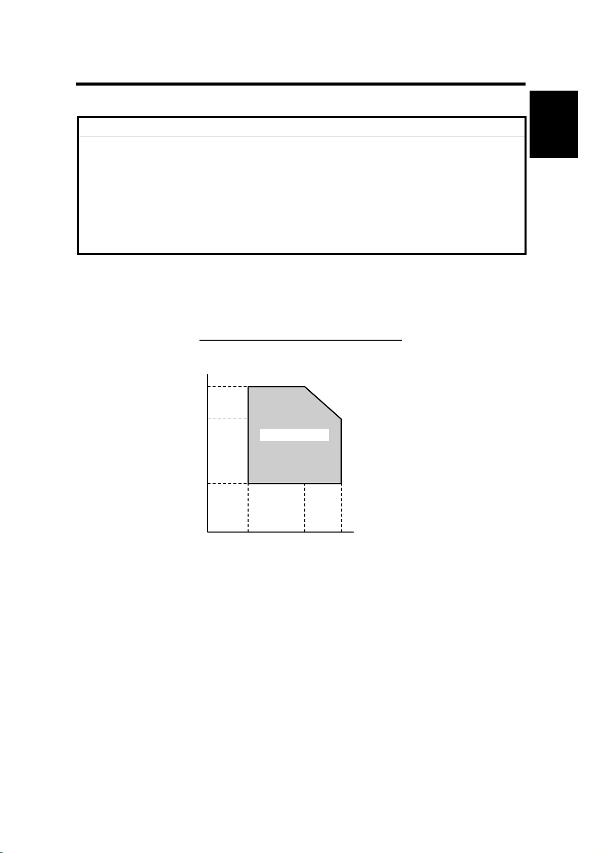
1.1.1 ENVIRONMENT
–Temperature and Humidity Chart–
Installation
Humidity
80%
54%
Operation range
15%
10°C
(50°F)
27°C
(80.6°F)
(89.6°F)
32°C
Temperature
B046I512.WMF
1. Temperature Range: 10°C to 32°C (50°F to 89.6°F)
2. Humidity Range: 15% to 80% RH
3. Ambient Illumination: Less than 1,500 lux (Do not expose to direct sunlight.)
4. Ventilation: Room air should turn over at least 3 times/hr/person
5. Ambient Dust Less than 0.1 mg/m
3
6. Do not install the machine where it will be exposed to direct sunlight or to direct
airflow (from a fan, air conditioner , air clean er, etc .) .
7. Do not install the machine where it will be exposed to corrosive gas.
8. Place the machine on a firm and level base.
9. Do not install the machine where it may be subjected to strong vibration.
1-1
Page 13
INSTALLATION REQUIREMENTS 24 July, 2001
1.1.2 MACHINE LEVEL
Front to back: Within 5 mm (0.2") of level
Right to left: Within 5 mm (0.2") of level
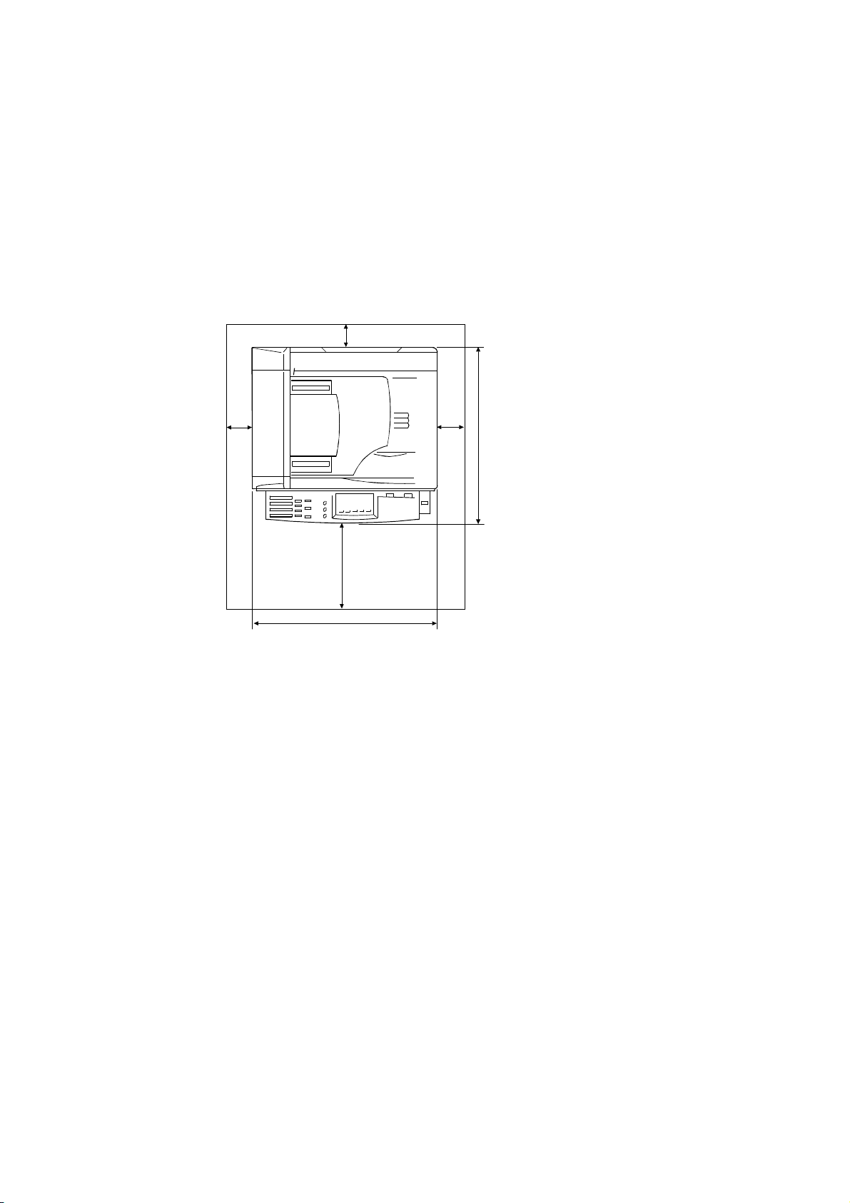
1.1.3 MINIMUM OPERATIONAL SPACE REQUIREMENTS
Place the machine near the power source, providing clearance as shown.
[C]
[D]
[B]
450 mm (17.7")
A: Front > 750 mm (29.6")
[A]
B: Left > 100 mm (3.9 ")
C: Rear > 105 mm (4.1")
D: Right > 230 mm (9.0")
468 mm (18.4")
B046I130.WMF
NOTE: 1) The 750-mm front space indicated above is sufficient to allow the paper
tray to be pulled out. Additional space is required to allow an operator to
stand at the front of the machine.
2) Actual minimum space requirement for left, rear, and right sides is
10mm (0.4") each, but note that this will not allow room for opening of
the bypass tray, right door, platen cover, or ADF unit.
1-2
Page 14

24 July, 2001 INSTALLATION REQUIREMENTS
1.1.4 POWER REQUIREMENTS
!
CAUTION
1. Make sure that the wall outlet is near the machine and easily accessible.
After completing installation, make sure the plug fits firmly into the
outlet.
2. Avoid multi-wiring.
3. Be sure to ground the machine.
Input voltage:
North America: 120 V, 60 Hz, 7 A
Europe: 220 – 240 V, 50/60 Hz, 4 A
Image quality guaranteed at rated voltage ± 10%.
Operation guaranteed at rated voltage ± 15%.
Installation
1-3
Page 15
COPIER 24 July, 2001
1.2 COPIER
1.2.1 ACCESSORY CHECK
Check that you have the accessories indicated below. Note that accessories vary
according to model and location.
No. Description Q’ty
1 Copier Operating Instructio ns (-17, -26, -29) 1
2 EU safety sheet (-22, -24, -26, -27) 1
3 NECR (-17, -27, -29) 1
4 Paper-size decals 1 set
5 Energy Star seal (-26) 1
6 Branding plaques (-22) 1 set
7 Brand decals (-22) 1 set
8 Handset bracket (B046-17) 1
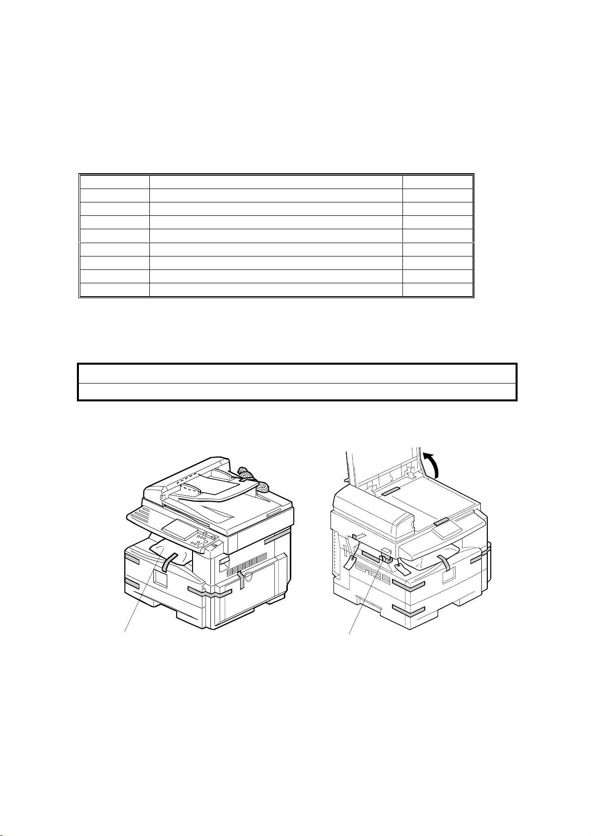
1.2.2 INSTALLATION PROCEDURE
!
CAUTION
Make sure that the copier remains unplugged during installation.
[A]
B046I101.WMF
[B]
B046I124.WMF
1. Remove the strips of tape.
2. Remove the bag [A] holding the included accessories.
3. Remove the spacing wedge [B].
1-4
Page 16
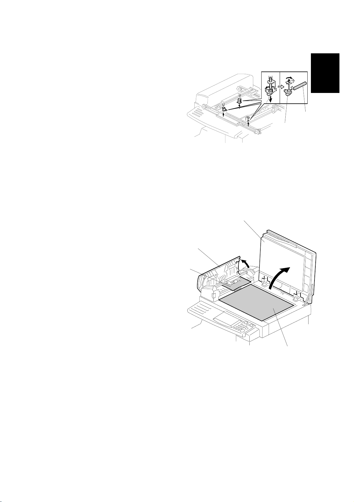
24 July, 2001 COPIER
4. Remove the 3 scanner lock pins. (A
tag is hanging from each pin.) To
remove: Grasp the base of the pin [A],
turn 90 degrees, and pull down and
out.
[B]
[A]
Installation
5. Remove the tags from the pins. Then
break each pin off of its base [A],
discard the pin part [B], and set each
base [A] back into its original hole,
turning it 90° to lock it into place. (Be
sure to do this for all three pins.)
6. If installing a DF-equipped model
(B046 or B049): Raise the DF upper
guide [C] and remove the protective
paper [D] at the feed unit. Then lower
the guide.
7. Open the platen cover [E] and remove
the protective paper [F] covering the
exposure glass. Then close the platen
cover.
B046I106.WMF
[E]
[C]
[D]
1-5
B046I107.WMF
[F]
Page 17
COPIER 24 July, 2001
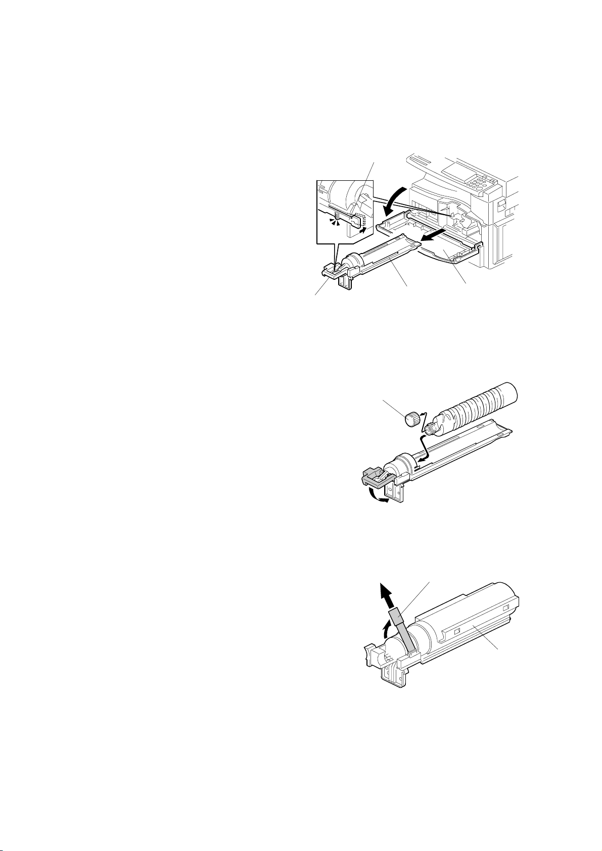
8. Open the front door [A].
9. If installing a toner-bottle model
(B044 or B046):
• Lift lever [B], press in on latch [C]
[C]
and pull the bottle holder [D] out.
(It is not necessary to pull it
completely out of the machine,
however.)
• Take a new bottle of toner, shake
it several times, remove its outer
cap [E], and load as shown. Then
push the bottle holder back into
the machine, and press the latch
[B]
[D]
[A]
down to lock it.
B046I112.WMF
If
installi
ng a toner-hopper magazine model
(B045 or B049):
• Shake the magazine several times, then
peel off the paper [F] from a new THM [G],
and load the THM into the machine.
[E]
B046I301.WMF
[F]
[G]
1-6
B046I114.WMF
Page 18
24 July, 2001 COPIER
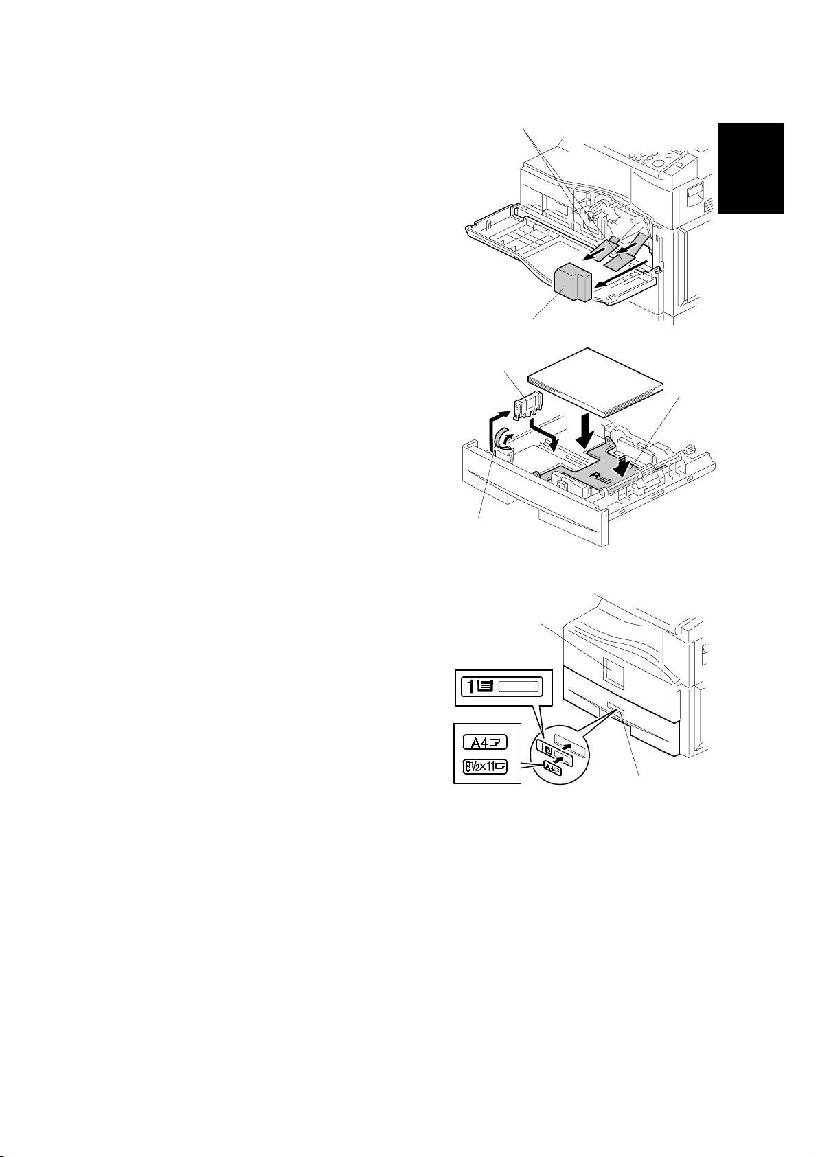
10. Remove the foam cushion [A] and pull the
tabbed strips [B] all the way out of the
PCU. Then close the front door.
11. Pull open the paper tray, and remove the
tape [C] securing the end fence in the
compartment.
12. Push the bottom plate [D] down, load
paper, and adjust the side fences. If
loading paper shorter than A4, remove
the end fence [E] from its compartment,
set it into the tray, and adjust it to the
correct length.
[B]
Installation
[A]
B046I104.WMF
[E]
[D]
[C]
B046I119.WMF
13. Push the tray back in.
14. Adhere the appropriate branding decal
(not shown) to the center of the front
[F]
door [F], and adhere the tray number
decal and appropriate paper- si ze decal
to the front of the paper tray (at [G]) as
shown.
15. Hong Kong only:
If installing model B046 or B049 in
Hong Kong, you must change the
position of the TB1 jumpe r on the NCU.
Turn to the fax service manual and carry
out steps 4 to 8 of the installation
[G]
B046I515.WMF
procedure (fax service manual, section 1.2.2).
16. Plug in the machine and turn on the main switch.
17. Enter SP mode, and run SP7-825 to initialize the electrical total counter to 0.
NOTE:
1) After selecting SP7-825, enter "1" and then hold down the Original
Type key and press the OK key to initialize the counter. If
initialization is successful, the screen displays "Action comp leted."
2) SP7-825 is effective only once, at time of machine installation .
1-7
Page 19

COPIER 24 July, 2001
18. Models B046 and B049 only: Access SP5-992 and select "2" to print out a full
SMC report. Confirm that the report shows a "YES" for SP7-801-3.
19. Models B046 and B049 only: Press the On Hook key on the fax operation
panel, and confirm that you hear a dial tone coming from the monitor speaker.
20. Program the required items, as indicated below.
Initial Programming: Faxless models (B044, B045)
Items to Program (Service Level – SP Mode)
Date and time 5-302
Language replacement (Fir mware download) 5-827
*1
*1: See Section 5 for SP-mode usage instructions.
Items to Program (User Level)
Display contrast
Energy saver level (low power mod e)
Reception mode
Other items, as necessary *2
*2
User Tools
User Tools →
System Settings
*2: Refer to the Operating Instructions for details.
Initial Programming: Fax-equipped models (B046, B049)
Items to Program (Service Level – Serv i ce Functions)
Country code (System switch 0F) 01
Protocol requirements (G3 switch 0 B) - E U only 01
PM call (System switch 01 – bit 0) 01
Country code (NCU parameter 0 0) 07
Service station's fax number 09
*3
Function No.
SP No.
*3: See Section 5.1.1 of the fax service manual for information abou t using
service functions.
1-8
Page 20

24 July, 2001 COPIER
Items to Program (Service Level – SP Mode)
*4
SP No.
Machine's serial number 5-811
Language replacement (Fir mware download) 5-827
PSTN access code (RAM address 4000DB)
PSTN access method (RAM address 4000CD)
7-955
Periodic service call (RAM addresses 40054F to 400553)
*4: See Section 5 for SP-mode usage instructions.
Items to Program (User Administrator Level)
Monitor volume
Display contrast
Date and Time
Reception mode
Fax Header/Own Name/Own No. (TTI/RTI/CSI)
Reports on/off
Country Code (except NA)
Fusing power control during e nergy saver mode System
Language selection Language
Other initial progr amming items *5
*5
User Tools
Fax Features
→ Setup
Key Op. Tools
Settings
Installation
*5: Refer to the Operating Instructions for details.
1-9
Page 21
PAPER TRAY UNIT 24 July, 2001
1.3 PAPER TRAY UNIT
1.3.1 ACCESSORY CHECK
Confirm that you have the accessories indicated below.
No. Description Q’ty
1 Paper-size decals 1 sheet
2 Installation Procedure (for service person) 1
3 Installation Procedur e (for us er) 1
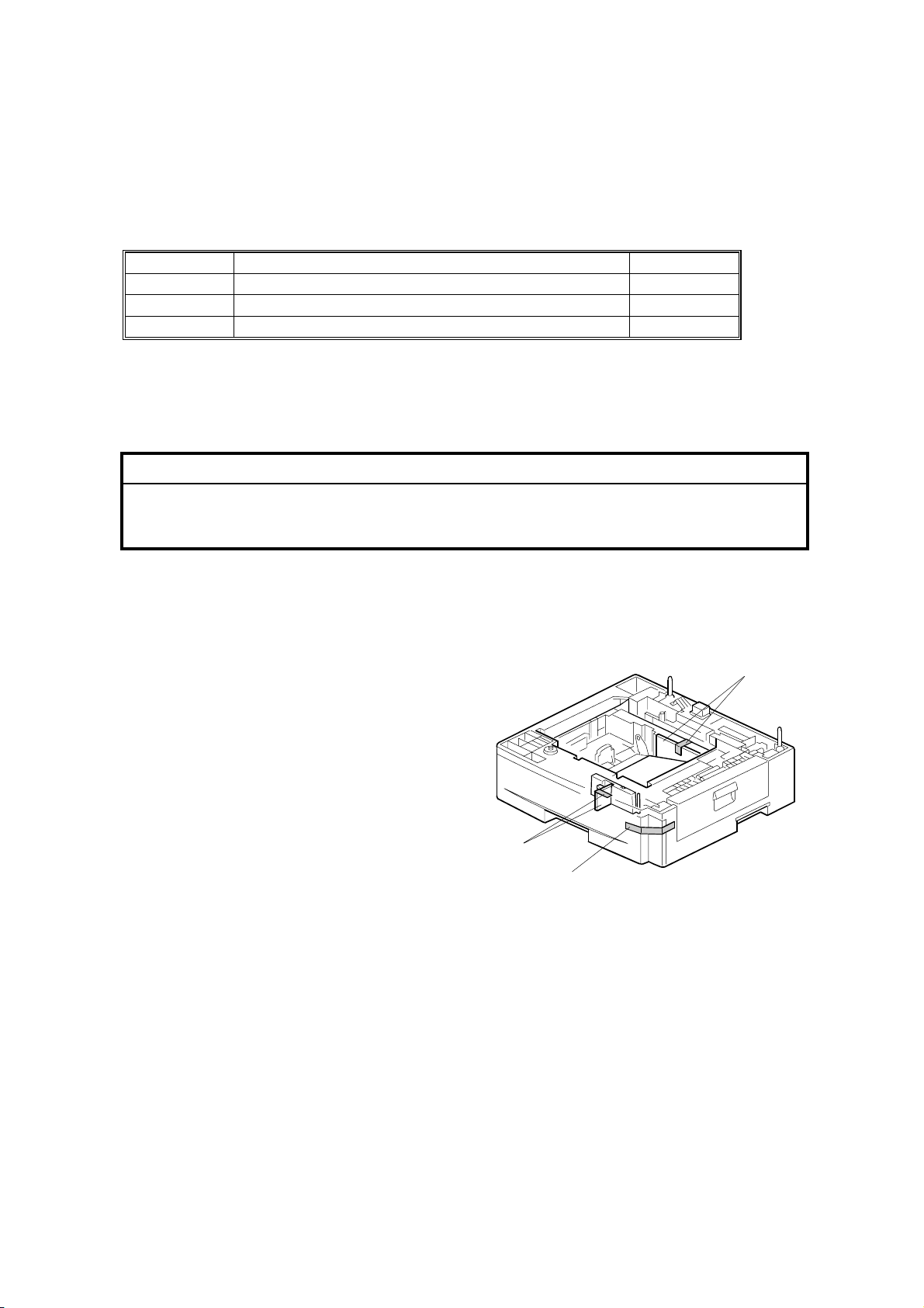
1.3.2 INSTALLATION PROCEDURE
!
CAUTION
Unplug the main machine's power cord before starting the following
procedure.
1. Remove the tape at [A], and the tape and cardboard at [B].
2. Pull the paper tray part way out of the unit, remove the tape and cardboard at
[C], and push the tray back in.
[B]
[C]
[A]
B046I516.WMF
1-10
Page 22
24 July, 2001 PAPER TRAY UNIT
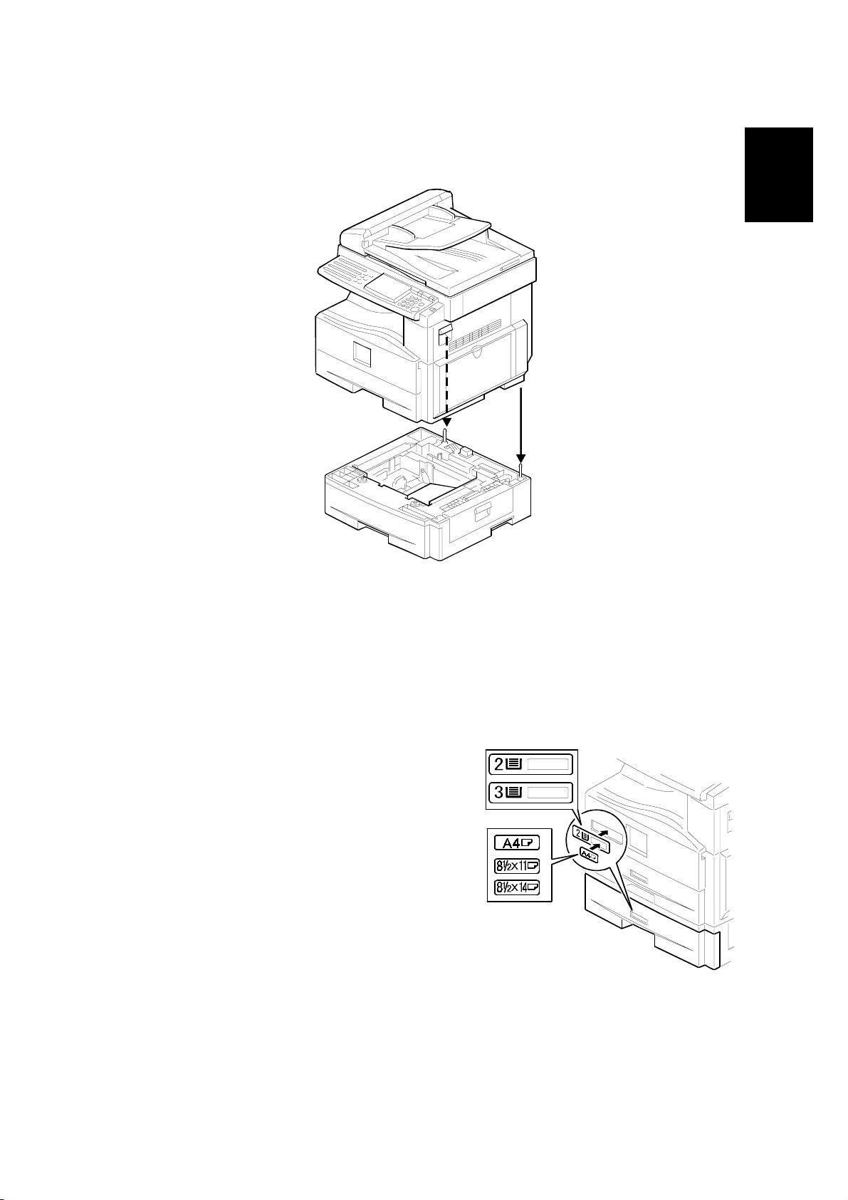
3. Set the machine onto the paper tray unit.
Installation
B046I527.WMF
4. Remove the paper tray from the paper tray unit.
5. Load paper into the paper tray. Adjust the side and end fences as necessary. If
loading 8
"x 14" paper, remove the end fence and set it into the special
1/2
compartment.
6. Set the paper tray back into the paper tray unit.
7. Stick on the appropriate tray-number
decal and paper-size decal, at the
locations indicated in the illustration.
B046I517.WMF
1-11
Page 23
PAPER TRAY UNIT HEATER 24 July, 2001
1.4 PAPER TRAY UNIT HEATER
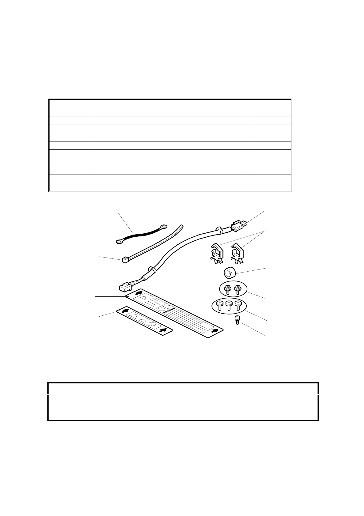
1.4.1 ACCESSORY CHECK
Confirm that you have the accessories indicated below.
No. Description Q’ty
1 Grounding wire 1
2 Relay harness 1
3Clamps 2
4 Ferrite core 1
5 Heater fastening screws 2
6 PTU fastening screws 3
7 Grounding screw 1
8 Decal for copier 1
9 Decal for paper unit 1
10 Tie wrap 1
1
10
9
8
1.4.2 INSTALLATION PROCEDURE
2
3
4
5
6
7
B046I518.WMF
!
CAUTION
Unplug the main machine's power cord before starting the following
procedure.
1. If the paper tray unit is already installed, uninstall it by lifting the copier off of it.
(Refer to illustrations for Procedure 1.3.2, above.)
2. Remove both paper trays—the one from the copier, and the one from the
paper tray unit.
1-12
Page 24
24 July, 2001 PAPER TRAY UNIT HEATER
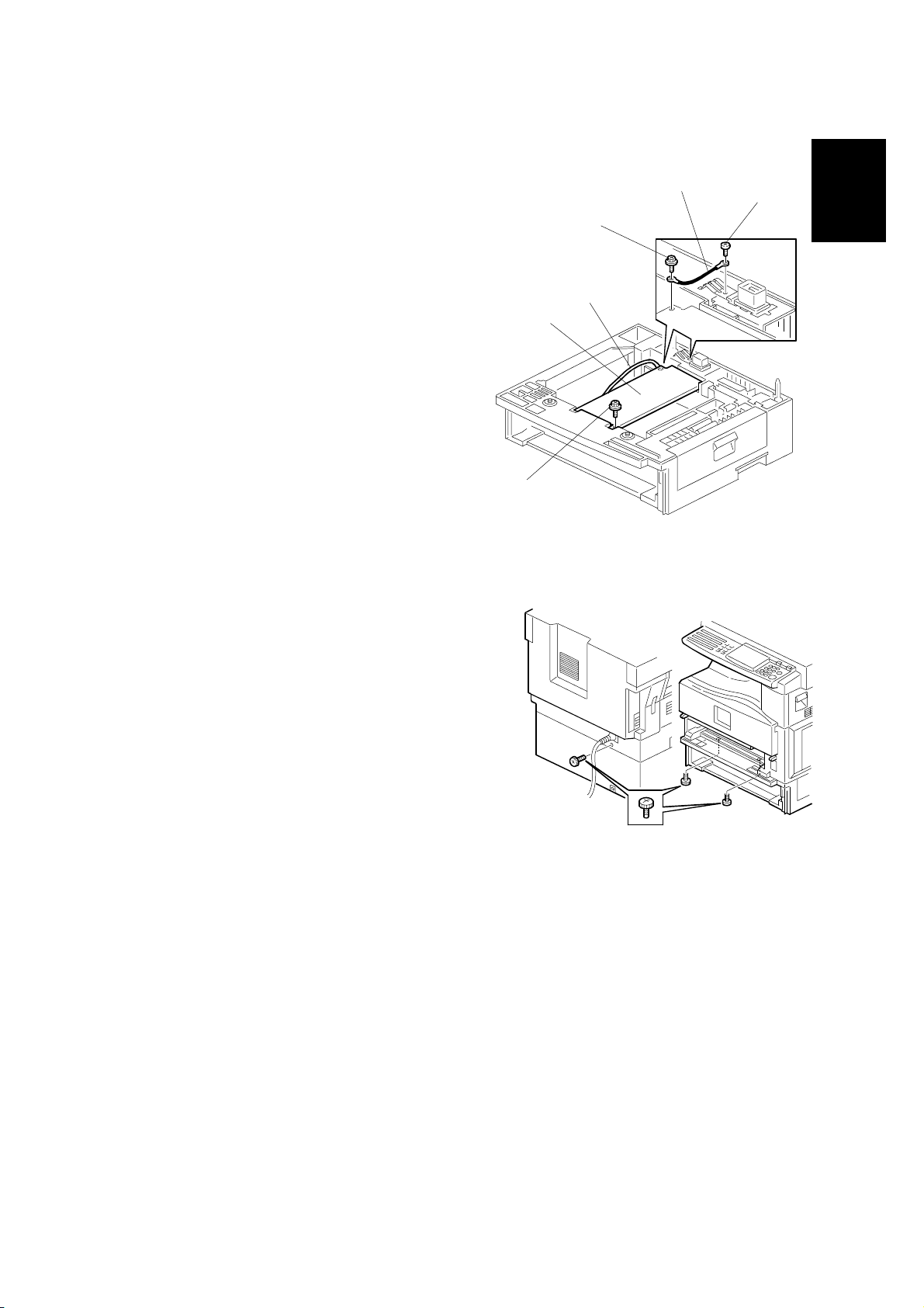
3. Remove the ground screw [A] at the rear of the paper tray unit.
4. Fasten the heater [B] and the supplied
ground wire [C] to the pa per tray unit
with 3 screws as shown. Note that [A]
is the grounding screw you removed at
Step 3 (returned to its original hole),
and [D] and [E] are the two supplied
heater fastening screws.
NOTE: Be sure to position the ground
wire [C] and heater harness [F]
so that they will be out of the
way of the copier when you set
it onto the paper tray unit.
5. Set the copier onto the paper tray unit.
6. Screw the paper tray unit into place using
three supplied PTU fastening screws.
[E]
[B]
[F]
[D]
[C]
[A]
Installation
B046I519.WMF
1-13
B046I500.WMF
Page 25
PAPER TRAY UNIT HEATER 24 July, 2001
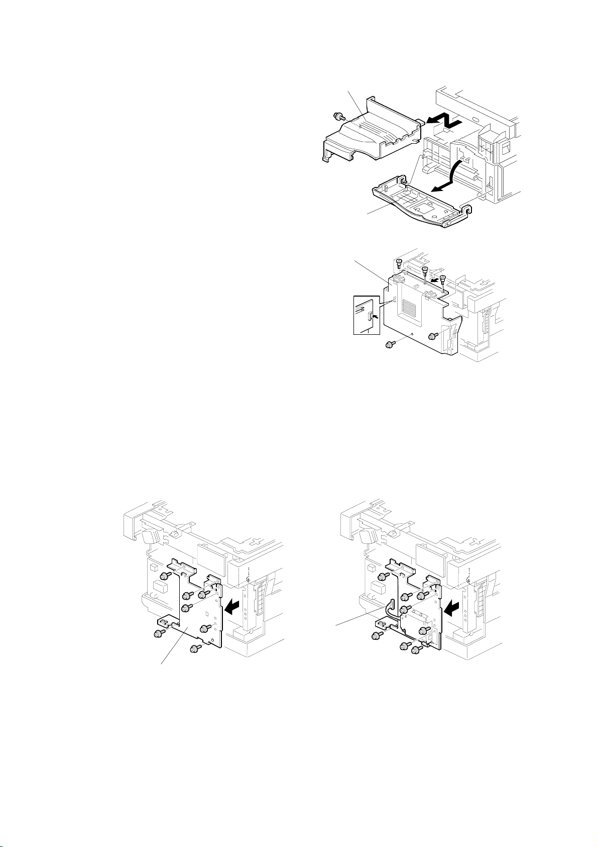
7. Open the front door [A] and remove the
copy tray [B] (!×1). Then close the
front door.
8. Remove the rear cover [C] (! x 5).
[B]
[A]
B046I501.WMF
[C]
B046I502.WMF
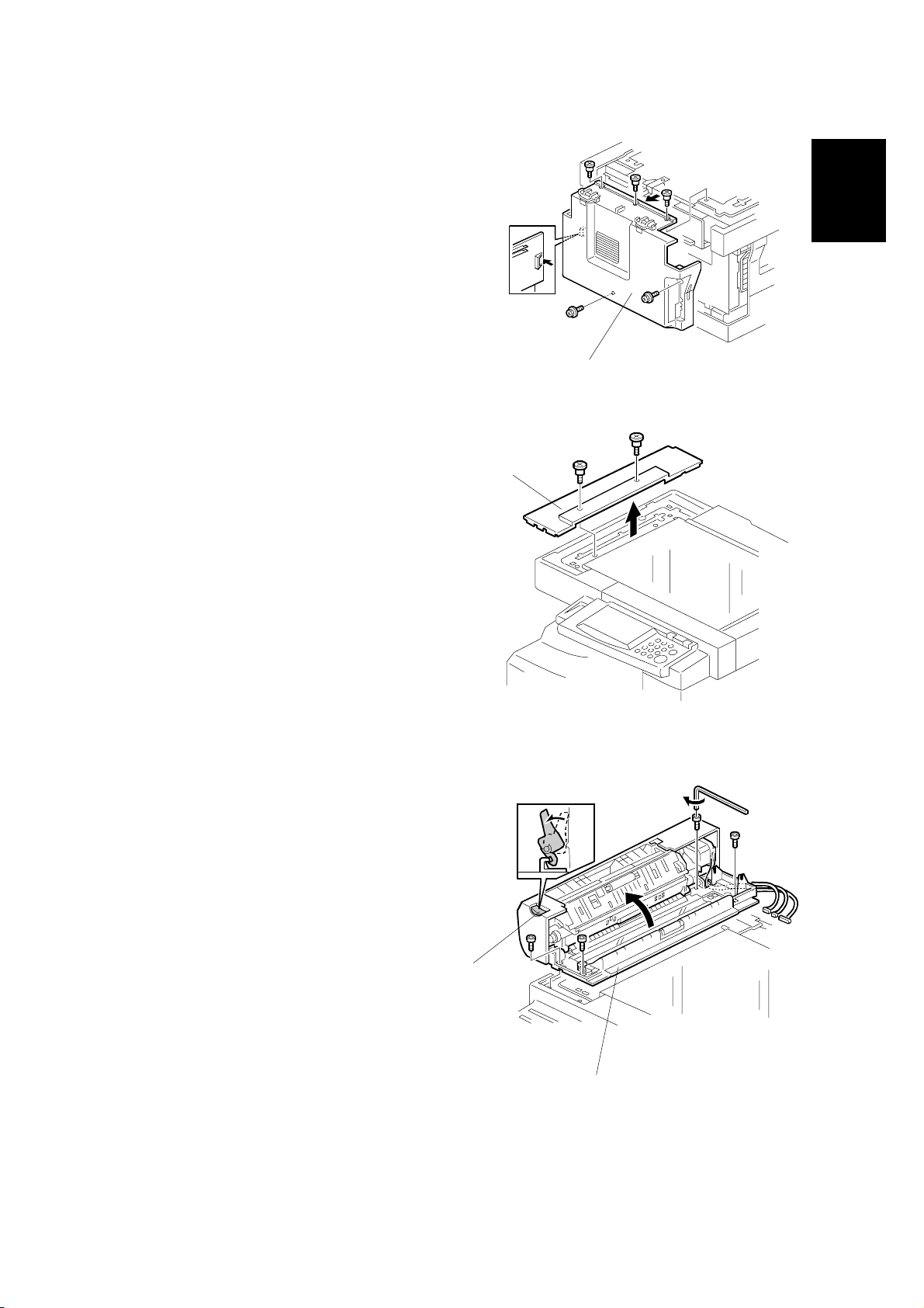
9. Remove the FCU cover plate [D] (7 screws on faxless machines, 8 screws on
fax-equipped machines) .
NOTE: On fax-equipped machines, detach the NCU connector [E] first.
Faxless machines: Fax-equipped machines:
[E]
[D]
B046I503.WMF
B046I504.WMF
1-14
Page 26
24 July, 2001 PAPER TRAY UNIT HEATER
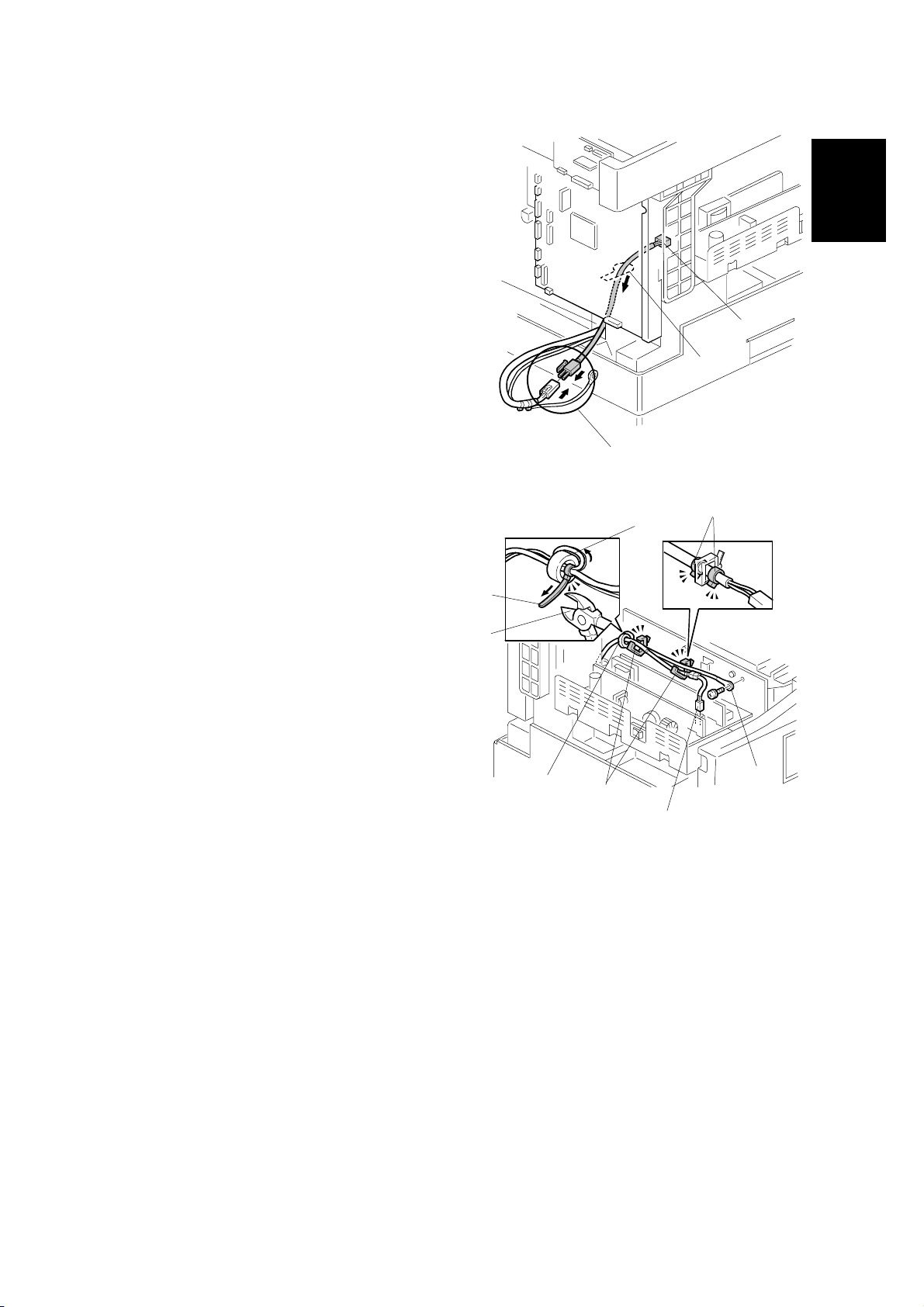
10. Pass the heater's harness through the
hole [A] at the rear of the copier.
11. Pass relay harness [B] through the
circular opening at [C] (at the rear of
[A]
the PSU board bracket), and then
through the hole at [A]. Then connect
[B]
the relay harness to the heater's
harness [D].
[C]
Installation
12. Pull the relay harness back into the
copier. Then set the ferrite core [E]
over the relay harness, and push it
back so that it is over the heater's
harness.
13. Wrap the heater's harness once
around the core (see [F]). Adjust so
that the core is located toward the
rear of the copier (at position [E],
behind the rear clamp). Secure the
core into position using the supplied
tie wrap [G].
14. Clip off the excess length of the tie
wrap [H].
[G]
[H]
[E]
[K]
[D]
B046I520.WMF
[L]
[F]
[J]
B046I521.WMF
[I]
15. Connect the relay harness connector [I] to the large connector at the front
center of the PSU board. Screw the ground wire [J] to the PSU board bracket,
using the included grounding screw.
16. Attach the supplied clamps [K] to corresponding holes on the PSU board
bracket, and set the heater harness though the clamps. Position the harness
so that the front clamp is between the two bindings [L] on the harness. Then
fasten the clamps.
1-15
Page 27
PAPER TRAY UNIT HEATER 24 July, 2001
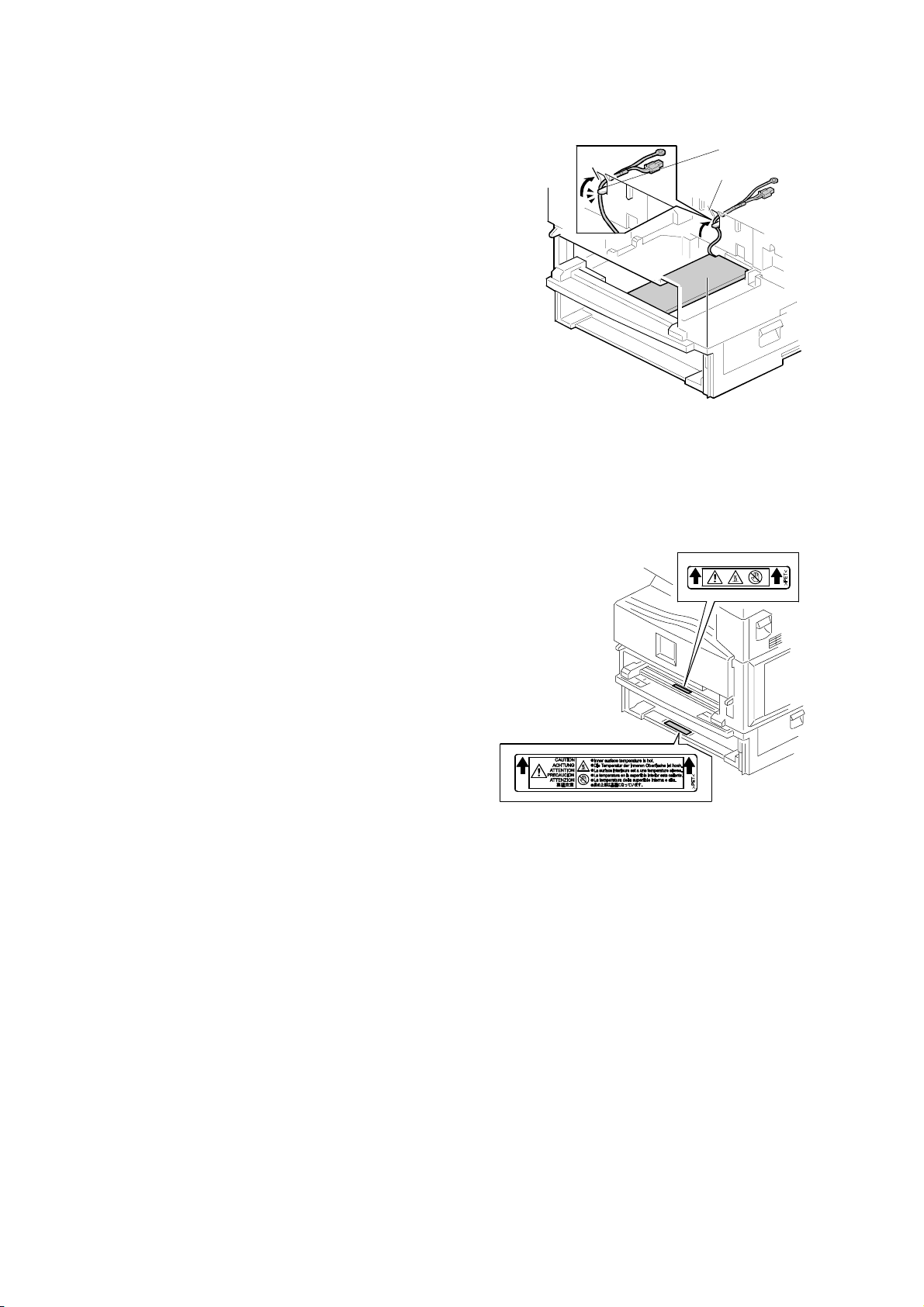
17. Pull the excess length of the heater's
harness out the hole at the rear [A].
NOTE: Be sure that the harness passes to
the side of the grounding plate [B]
at the bottom of the hole. (The front
of the grounding plate must remain
clear.)
18. Arrange the excess harness length so that it sits beneath the
FCU cover plate.
19. Attach the caution decals
to the locations shown in
the illustration.
[B]
[A]
B046I522.WMF
20. Reinsert the paper trays, and reattach the copy tray and the rear cover.
1-16
B046I523.WMF
Page 28
24 July, 2001 DOCUMENT FEEDER
1.5 DOCUMENT FEEDER
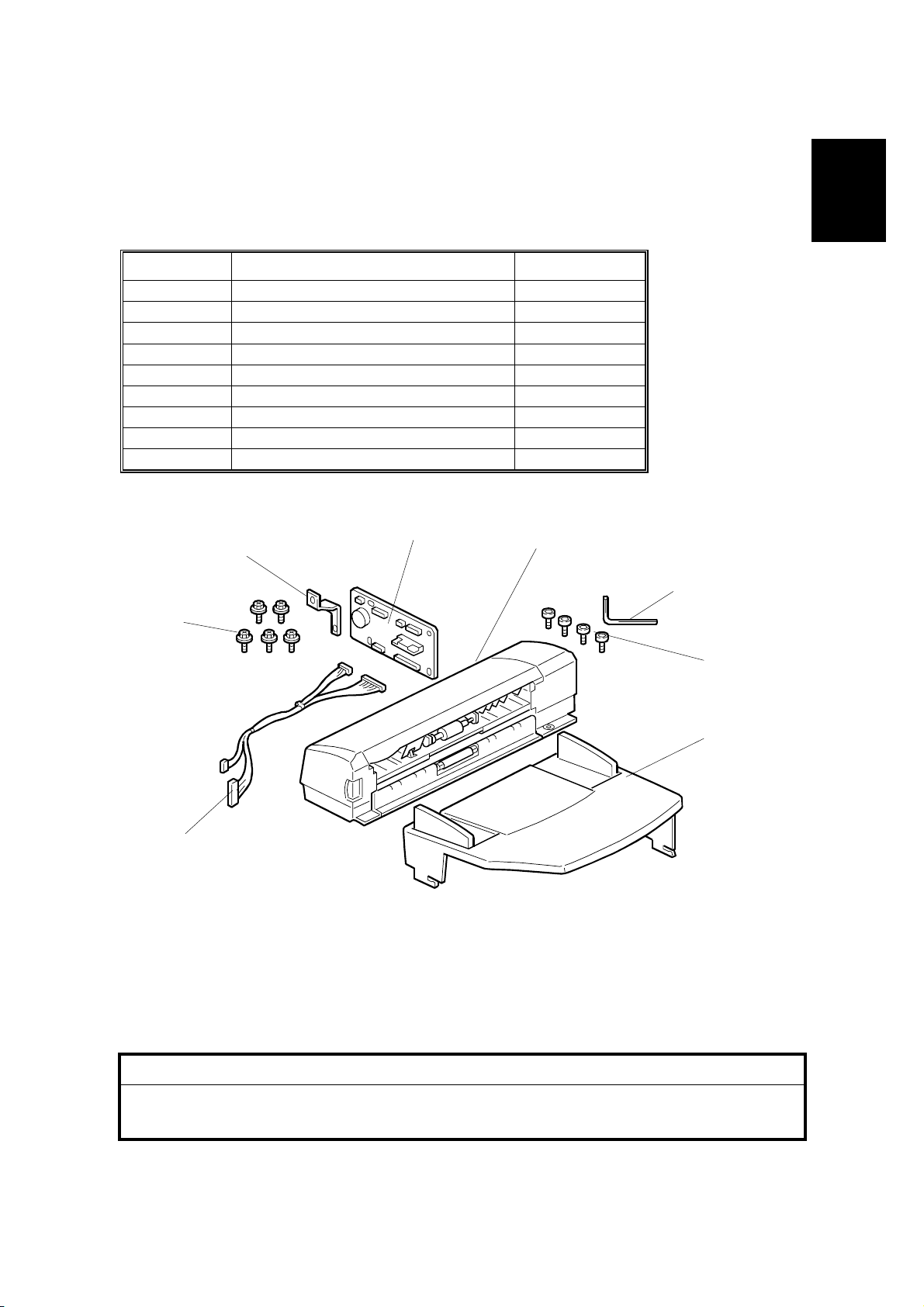
1.5.1 ACCESSORY CHECK
Confirm that you have the components and accessories indicated below.
No. Description Q’ty
1 DF connection board 1
2 DF body 1
3 Hex wrench 1
4Hex screws 4
5 DF original tab le 1
6 Wire harness 1
7 Phillips-head screws 5
8Bracket 1
– Installation Procedure 1
1
8
2
3
7
Installation
4
6
B046I524.WMF
1.5.2 INSTALLATION PROCEDURE
!
CAUTION
Unplug the main machine's power cord before starting the following
procedure.
5
1-17
Page 29

DOCUMENT FEEDER 24 July, 2001
1. Unpack the ADF and remove the packing
tape from the bottom of the ADF body.
[C]
2. Remove the platen cover [A]. To
[A]
remove: Lift the cover, unlatch the
two latches [B] (press down on
the tabs [C] and push the latch
back), and detach the cover from
the hook [D].
[B]
[D]
B046I505.WMF
3. Remove the left piece [E] of the copier's
platen cover by pushing the piece to the
left and then pulling it up and off.
4. Place the DF original table [F] flat onto
the platen cover, so that the 3 latches
go all the way into the openings and so
that the contact area [G] around each
latch is flush against the cover. Then
push so that latch [1] locks into place,
then latch [2], and then latch [3] (at the
rear left).
NOTE: The latches may break if you
try to push the table in at an
angle.
[E]
[1]
[3]
B046I525.WMF
[F]
[2]
[G]
B046I526.WMF
1-18
Page 30
24 July, 2001 DOCUMENT FEEDER
5. Remove the rear cover [A] (! x 5).
[A]
B046I514.WMF
6. Remove the left scale plate [B] (! x 2).
[B]
Installation
7. Set the DF body [C] onto the copier
in its correct position. Press the latch
[D] to raise the top half of the body,
and fasten to the copier with the 4
hex screws (using the included hex
wrench).
B046I506.WMF
[D]
B046I528.WMF
[C]
1-19
Page 31

DOCUMENT FEEDER 24 July, 2001
[B]
8. Install the DF connection board [A] and DF board bracket [B]. (! x 5)
[D]
[C]
[A]
B046I513.WMF
9. Connect the four wire sets from the DF body to CN103, CN105, CN106, and
CN107 on the DF connection board. (Not shown in illustration.)
10. Connect one end of the supplied wire harness [C] to CN101 and CN102 on the
DF connection board, and connect the other end to connectors CN9 and CN10
on the FCU. Secure the wire harness into the clamp [D] located to the side of
the DF board.
11. Reattach the rear cover and the platen cover.
12. Plug in the power cord, and turn on the main switch.
13. Make a full-size copy from the first tray using the ADF, and check the side-toside and leading edge registrations. If the registration is incorrect, adjust as
necessary (☛ 3.13.3).
1-20
Page 32

24 July, 2001 DIMM
1.6 DIMM
1.6.1 INSTALLATION PROCEDURE
!
CAUTION
Unplug the main machine's power cord before starting the following
procedure.
1. Remove the rear cover [A] (! x 5).
Installation
[A]
B046I508.WMF
2. Remove the FCU cover plate [B] (7 screws on faxless machines, 8 screws on
fax-equipped machines) .
NOTE: On fax-equipped machines, detach the NCU connector [C] first.
Faxless machines: Fax-equipped machines:
[C]
[B]
B046I509.WMF
B046I510.WMF
1-21
Page 33

DIMM 24 July, 2001
3. Insert the DIMM [A] at an angle into slot
CN2 on the FCU.
4. Press the free end of the DIMM toward
the FCU, so that the DIMM snaps into
place parallel to the FCU.
5. Reinstall the FCU cover plate and the
rear cover.
[A]
B046I105.WMF
1-22
Page 34

24 July, 2001 PM TABLES
2. PREVENTIVE MAINTENANCE SCHEDULES
2.1 PM TABLES
NOTE: 1) After carrying out PM, clear the PM counter (SP7-804).
2) PM intervals (45k, 90k) indicate the number of prints.
Key: AN: As necessary C: Clean R: Replace I: Inspect
Every
45k
OPTICS
Reflector C C Optics cloth
1st mirror C C Optics cloth
2nd mirror C C Optics cloth
3rd mirror C C Optics cloth
Platen cover C C Dry cloth
Exposure glass C C Dry cloth
Toner shield glass C C Dry cloth
DRUM AREA
PCU R
Transfer roller R
Discharge plate R
PAPER FEED
Paper feed roller R C Water or alcohol.
Friction pad R C Dry cloth
Bottom-plate pad C C Water or alcohol.
Registration roller C C Water or alcohol.
Every
90k
AN NOTE
On B044 and B046: Als o cl ean
toner-bottle holder.
Preventive
Maintenance
FUSING UNIT
Hot roller R
Pressure roller R
Hot roller bearings R
Pressure-roller
bushings
Inlet guide C
Outlet guide C
Hot roller stripper
pawls
Thermistor C
R
I
2-1
Page 35

HOW TO CLEAR THE PM COUNTER 24 July, 2001
Every
90k
DF
Separation roller R C Water or alcohol
Pick-up roller R C Water or alcohol
White plate C Water or alcohol
DF exposure glass C Water
Rollers R0, R1, R2 C Water or alcoho l
Every
120k
PAPER TRAY UNIT
Paper feed roller R
Bottom-plate pad C Dry cloth
Friction pad R
AN NOTE
AN NOTE
2.2 HOW TO CLEAR THE PM COUNTER
After finishing PM, clear the PM counter as follows.
1. Access SP mode 7-804.
2. Hold down the Original Type key and press the OK key (or ! key) to reset the
counter. If the reset is successful, the display shows “Action completed.” If the
reset fails, the display shows “Error!!!”
2-2
Page 36

24 July, 2001 PRECAUTIONS
3. REPLACEMENT AND AD JUSTMENT
3.1 PRECAUTIONS
3.1.1 GENERAL
!
CAUTION
Turn off the main power switch and unplug the machine before starting any
of the replacement procedures described in this section.
But note that you should not turn off the main switch while mechanical parts are
active, as this may cause parts to stop out of home position. Attempting to remove
or install the PCU or other such units while parts are out of home position may
result in damage. Wait for operation to stop before turning off the machine.
3.1.2 LITHIUM BATTERIES
!
CAUTION: Lithium Batteries
Incorrect replacement of lithium battery(s) on the FCU poses risk of
explosion. Replace only with the same type or with an equivalent type
recommended by the manufacturer. Discard used batteries in accordance
with the manufacturer’s instructions.
Adjustment
Replacement
3.1.3 PCU (PHOTOCONDUCTOR UNIT)
The PCU consists of the OPC drum, charge roller, development unit, and cleaning
components. Observe the following precautions when handling the PCU.
1. Never touch the drum surface with bare hands. If the drum surface is dirty or if
you have accidentally touched it, wipe it with a dry cloth, or clean it with wet
cotton and then wipe it dry with a cloth.
2. Never use alcohol to clea n the drum. Alcohol will dissolve the drum surfac e.
3. Store the PCU in a cool dry place.
4. Do not expose the drum to corrosive gases (ammonia, etc.).
5. Do not shake a used PCU, as this may cause toner and developer to spill out.
6. Dispose of used PCU components in accordance with local regulations.
3.1.4 TRANSFER ROLLER
1. Never touch the surface of the transfer roller with bare hands.
2. Be careful not to scratch the transfer roller, as the surface is easily damaged.
3-1
Page 37

PRECAUTIONS 24 July, 2001
3.1.5 SCANNER UNIT
1. Use alcohol or glass cleaner to clean the exposure and scanning glass. This
will reduce the static charge on the glass.
2. Use a blower brush or a water-moistened cotton pad to clean the mirrors and
lenses.
3. Take care not to bend or crease the exposure lamp’s ribbon cable.
4. Do not disassemble the lens unit. Doing so will throw the lens and copy image
out of focus.
5. Do not turn any of the CCD positionin g screws. Doing so will throw the CCD out
of position.
3.1.6 LASER UNIT
1. Do not loosen or adjust the screws securing the LD drive board on the LD unit.
Doing so will throw the LD unit out of ad justment.
2. Do not adjust the variable resistors on the LD unit, as these are permanently
adjusted at the factory. If replacement of the LD drive board is necessary,
replace the entire LD unit.
3. Keep the polygon mirror and toroidal lens free of dust. Laser performance is
very sensitive to dust on these components.
4. Do not touch the shield glass, the lenses, or the surface of the polygon mirror
with bare hands.
3.1.7 FUSING UNIT
1. After installing the fusing thermistor, make sure that it is in contac t with the hot
roller and that the roller can rotate freely.
2. Be careful to avoid damage to the hot roller stripper pawls and their tension
springs.
3. Do not touch the fusing lamp and rollers with bare hands.
4. Make sure that the fusing lamp is positioned correctly and that it does not touch
the inner surface of the hot roller.
Adjustment
Replacement
3.1.8 PAPER FEED
1. Do not touch the surface of paper feed rollers.
2. To avoid misfeeds, the side and end fences in each paper tray must be
positioned correctly so as to align with loaded paper size.
3-2
Page 38

24 July, 2001 SPECIAL TOOLS AND LUBRICANTS
3.1.9 IMPORTANT
1. The machine will automatically start toner agitation when you install a new
PCU. Be sure to wait for initialization to finish before reopening the front cover
or turning off the main switch.
2. If the optional anti-condensation heater (for the optional paper tray unit) is
installed, keep the copier's power cord plugged in even while the main switch is
off, so that the heater remains energized.
3.2 SPECIAL TOOLS AND LUBRICANTS
Part Number Description Q’ty Common with...
A1849501 Optics Adjustment Tools (2 pcs/set ) 1 set Skylark
A2929500 Test Chart – S5S (10 pcs/set) 1 set Mojito
A0299387 Digital Multimeter – F lu k e 87 1 Russian-C, Stinger-C
N8036701 Flash Memory Card (4MB) 1 Russian-C, Stinger-C
N8031000 Case for Flash Memory Card 1 Russian-C, Stinger-C
A2579300 Grease Barrierta – S552R 1 Russian-C, Stinger-C
52039501 Silicone Grease G-501 1 Russian-C, Stinger-C
G0219350 Loop back connector 1 Russian-C, Stinger-C
Adjustment
Replacement
3-3
Page 39

EXTERIOR COVER AND OPERATION PANEL 24 July, 2001
[C]
3.3 EXTERIOR COVER AND OPERATION PANEL
3.3.1 PLATEN COVER
1. Lift the platen cover [A].
2. Unlatch the two latches [B].
NOTE: To unlatch, press down on the tabs [C] and then push the latch back.
3. Detach the cover from the hook [D]
[A]
[B]
[D]
Adjustment
Replacement
3.3.2 REAR COVER
1. Platen cover (☛ 3.3.1)
2. Rear cover [A] (! x 5)
B046R904.WMF
[A]
B046R903.WMF
3-4
Page 40

24 July, 2001 EXTERIOR COVER AND OPERATION PANEL
3.3.3 COPY TRAY
1. Open the front door [A].
2. Copy tray [B] (! x 1)
[B]
[A]
3.3.4 SCALE PLATE (B044 AND B045 ONLY)
1. Scale plate [A] (! × 2)
[A]
B046R912.WMF
Adjustment
Replacement
3-5
B046R551.WMF
Page 41

EXTERIOR COVER AND OPERATION PANEL 24 July, 2001
3.3.5 LEFT COVER
1. Rear cover (☛ 3.3.2)
2. Slide the left cover [A] toward the rear to remove it.
[A]
[B]
[C]
[E]
[D]
Adjustment
Replacement
[F]
[G]
B046R901.WMF
3.3.6 RIGHT COVER
1. Rear cover (☛ 3.3.2)
2. Remove the metal fitting [B], and the platen-cover arm [C].
3. Slide the right cover [D] toward the rear to remove it.
3.3.7 FRONT LEFT COVER AND OPERATION PANEL
1. Front left cover [E] (On B044/5: ! × 2) (On B046/9: ! × 2, " × 2)
NOTE: The illustration shows B046/9.
2. Operation panel [F] (! × 4, " × 1)
3.3.8 FRONT RIGHT COVER
1. Operation panel (☛ 3.3.7)
2. Open the right door.
3. Front right cover [G]
3-6
Page 42

24 July, 2001 EXTERIOR COVER AND OPERATION PANEL
3.3.9 RIGHT DOOR
1. Open the right door [A].
2. Undo the strap [B].
3. Right door (" × 1)
3.3.10 BYPASS TRAY (B044 AND B046 ONLY)
1. Press the stopper rails [A] inward and
remove the bypass tray [B].
[B]
[A]
B046R909.WMF
Adjustment
Replacement
3-7
[B]
[A]
B046R908.WMF
Page 43

EXTERIOR COVER AND OPERATION PANEL 24 July, 2001
3.3.11 PLATEN COVER SENSOR
1. Rear cover (☛ 3.3.2)
2. Platen cover sensor [A] (" × 1)
[A]
B046R931.WMF
Adjustment
Replacement
3-8
Page 44

24 July, 2001 SCANNER SECTION
3.4 SCANNER SECTION
3.4.1 EXPOSURE GLASS
[A]
[B]
Adjustment
Replacement
B046R005.WMF
Non-DF machines
1. Rear cover (☛ 3.3.2)
2. Scale plate (☛ 3.3.4)
3. Exposure glass [A]
DF-equipped machines
1. Rear cover (☛ 3.3.2)
2. Right cover (☛ 3.3.6)
3. Exposure glass [A]
NOTE: When reinstalling: Be sure that the marking on the glass is at the rear left
corner, and be sure the left edge of the glass is aligned flush against the
support ridge [B] on the frame.
3-9
Page 45

SCANNER SECTION 24 July, 2001
3.4.2 LENS BLOCK
1. Exposure glass (☛ 3.4.1)
2. Unclamp four clamps [A], and take
[A]
the wire out of the clamps.
3. Lens block [B] (! × 4, 1 flat cable)
NOTE: 1) Do not loosen the paint-
locked screws holding the
lens unit in place.
2) After installing a new lens
block, carry out copy
adjustments. (☛ 3.13)
3.4.3 EXPOSURE LAMP, LAMP STABILIZER BOARD
1. Exposure glass (☛ 3.4.1)
2. Operation panel (☛ 3.3.7)
[E]
[B]
B046R003.WMF
[B]
Adjustment
Replacement
3. Slide the 1st scanner to a position
where the lamp and scanner are clear
of the metal lids.
4. Disconnect the lamp connector [A].
5. Remove either or both of the following:
• Exposure lamp [B] (1 screw at [C])
• Lamp stabilizer board [D] (2 screws
at [E], 1 flat cable)
[D]
[A]
[C]
B046R001.WMF
3-10
Page 46

24 July, 2001 SCANNER SECTION
3.4.4 SCANNER MOTOR
1. Right cover (☛ 3.3.6)
2. Scanner motor [A] (! × 4, 1 spring,
[A]
" × 1)
NOTE: When reinstalling: Fasten the
screws loosely, then set the
spring in place, then tighten up
the screws.
B046R923.WMF
3.4.5 SCANNER HP SENSOR
Adjustment
Replacement
1. Left cover (☛ 3.3.6)
2. If non-DF machine: Scale plate
(☛ 3.3.4)
If DF-equipped machine: Press on the
DF latch and open the DF.
3. Scanner HP sensor [A] (" × 1)
[A]
B046R020.WMF
3-11
Page 47

SCANNER SECTION 24 July, 2001
3.4.6 SCANNER ALIGNMENT ADJUSTMENT
1. Remove the rear cover (☛ 3.3.2), operation panel (☛ 3.3.7), and exposure
glass (☛ 3.4.1).
2. Loosen the 2 screws holding the 1st and
2nd scanner belts in place.
Adjustment
Replacement
B046D002.WMF
3. Slide the 1st and 2nd scanners so that all four of the following are roughly
aligned on both the front and back sides:
• The hole on the copier's lid
• The hole on the 1st scanner
• The corner right hole on the 2nd scanner
• The hole at the base of the scanner
[A]
4. Insert the two optics adjustment tools
[A], and adjust the scanne rs as
necessary so that the tools go through
all four holes.
5. Tighten the two screws that you
loosened at step 2 above, so that the
belts are firmly clamped into place.
6. Remove the adjustment tools.
3-12
B046D003.WMF
Page 48

24 July, 2001 FUSING
3.5 FUSING
3.5.1 FUSING UNIT
!
CAUTION
The fusing unit can become very hot. Be sure that it has cooled down
sufficiently before handling it.
1. Turn off the main switch, and unplug the machine.
2. Copy tray (☛ 3.3.3)
3. Fusing unit [A] (! × 3, " × 3)
NOTE: When reinstalling the unit:
Replace the spacer [B] in the
correct position, and
remember to set the
grounding wire [C] into place.
3.5.2 EXIT SENSOR
1. Fusing unit (☛ 3.5.1)
2. Exit sensor [A] (" × 1)
[B]
[A]
[C]
B046R501.WMF
Adjustment
Replacement
3-13
[A]
B046R508.WMF
Page 49

FUSING 24 July, 2001
3.5.3 HOT ROLLER STRIPPER PAWLS
[A]
[B]
B046R502.WMF
[E]
Adjustment
Replacement
[D]
B046R507.WMF
[C]
1. Fusing unit (☛ 3.5.1)
2. Separate the fusing unit into two sections: the hot roller section [A], and the
pressure roller section [B]. (! × 2)
NOTE: After removing the screws, lower the pressure roller section about
halfway and then slide it toward the front side to detach it.
3. Hot roller stripper pawls [C] (1 spring for each pawl)
NOTE: 1) To remove the right pawl, first remove the plastic spacer at [D]
(! × 1).
2) When re installing the center p awl, be sure to set roller [E] back
into place.
3-14
Page 50

24 July, 2001 FUSING
3.5.4 HOT ROLLER & FUSING LAMP
[A]
1. Hot roller stripper pawls (☛ 3.5.3)
2. Hot roller assembly [A] (! × 2)
NOTE: 1) Each of the screws has a
washer.
2) After removing the screws,
lift the hot roller assembly
out from the rear side.
3. Fusing lamp [B]
B046R505.WMF
[B]
4. Hot roller [C] (2 C-rings, 1 spacer,
1 gear, 2 bus hings)
[B]
Adjustment
Replacement
[C]
3.5.5 THERMOFUSE, THERMOSWITCH, AND THERMISTOR
1. Remove the hot roller assembly
from the hot roller section.
(☛ 3.5.3)
2. Thermofuse [A] (! × 2).
3. Thermoswitch [B] (! × 2)
NOTE: You must remove the
thermofuse first.
[B]
4. Thermistor [C] (! × 1)
B046R509.WMF
[C]
[A]
B046R506.WMF
3-15
Page 51

FUSING 24 July, 2001
3.5.6 PRESSURE ROLLER
1. Fusing unit (☛ 3.5.1)
2. Separate the fusing unit into two
sections: the hot roller section and the
pressure roller section (☛ 3.5.3, Step 2).
Carry out the remaining steps on the
pressure roller section.
3. Fusing entrance guide [A]
4. 2 springs ([B], [C])
5. 2 pressure arms ([D], [E])
NOTE: Manipulate each arm so
that it comes out through
the slit in the casing.
6. 2 bushings ([F], [G])
[H]
[A]
[B]
[D]
B046R504.WMF
[C]
[E]
[G]
Adjustment
Replacement
7. Pressure roller [H]
[F]
B046R503.WMF
3-16
Page 52

24 July, 2001 PCU
3.6 PCU
[A]
[B]
Adjustment
Replacement
B046I109.WMF
1. Open the right door.
NOTE: Do not forget to open the right door. The PCU may become stuck if
you try to remove it while the front door is closed.
2. Open the front door.
3. Remove the toner bottle holder or THM.
NOTE: If working on a toner-bottle model, clean away all spilled toner from the
toner bottle area and from the inside of the front door.
4. Detach the connector [A] and pull out the PCU [B].
NOTE: 1) After installing the new PCU, be sure to remove the Styrofoam piece
and to pull off the two tags. (☛ 1.1.2, Step 10)
2) The machine will automatically detect the new PCU and begin toner
initialization. (☛ 6.10.4)
3-17
Page 53

TONER SUPPLY CLUTCH 24 July, 2001
3.7 TONER SUPPLY CLUTCH
[C]
[A]
[B]
Adjustment
Replacement
B046R932.WMF
1. Remove the toner bottle or THM.
2. Copy tray (☛ 3.3.3)
3. Rear cover (☛ 3.3.2)
4. Disconnect the connector on C19 on the FCU.
5. Reach into to the machine and push the clutch coupler [A] toward the rear, and
at the same time reach around the back and remove the clip ring [B].
6. Remove the cone and spring, then lift the toner supply clutch mech anism [C]
out of its housing and remove it.
NOTE: When removing, note how the wire goes through a clamp, and also
note where it passes through the rear of the machine.
3-18
Page 54

24 July, 2001 PAPER FEED SECTION
3.8 PAPER FEED SECTION
3.8.1 PAPER FEED ROLLER AND FRICTION PAD
1. Take out the paper tray.
2. Clip ring [A]
3. Pull the shaft back, and lift it out.
4. Remove either or both of the following:
• Paper feed roller [B]
• Friction pad [C]
3.8.2 PAPER END SENSOR
1. Take out the paper tray.
2. Open the right door.
[A]
[B]
[C]
B046R702.WMF
Adjustment
Replacement
3. PCU (☛ 3.5)
4. Paper end sensor [A] (" × 1)
NOTE: When installing the new sensor,
reach your left hand in through the
front and your right hand in
through the right side, and view
from the right side.
B046R929.WMF
[A]
3-19
Page 55

PAPER FEED SECTION 24 July, 2001
3.8.3 REGISTRATION SENSOR
[C]
[A]
B046R926.WMF
1. Take out the paper tray.
2. Open the right door.
[B]
B046R927.WMF
Adjustment
Replacement
3. Black guide piece [A]
4. Registration sensor feeler [B]
5. Registration sensor [C] (" × 1)
3.8.4 BYPASS PAPER END SENSOR (B044 AND B046 ONLY)
1. Right door (☛ 3.3.9)
2. Detach the sensor compartment [A].
3. Bypass paper end sensor [B] (" × 1)
[A]
3-20
B046R924.WMF
[B]
Page 56

24 July, 2001 PAPER FEED SECTION
3.8.5 BYPASS FEED ROLLER (B044 AND B046 ONLY)
[B]
[A]
B046R938.WMF
[D]
[E]
[C]
[A]
[B]
B046R930.WMF
1. Right door (☛ 3.3.9)
2. Unscrew the feed roller frame [A] (! × 2) and rotate it about the feed roller
shaft [B] so that it is upside down.
3. Detach the feed roller shaft [B] from the feed roller frame (unsnap the two snap
pawls [C] and remove the spacer [D]).
4. Bypass feed roller [E]
Adjustment
Replacement
3-21
Page 57

PAPER FEED SECTION 24 July, 2001
3.8.6 BYPASS FEED CLUTCH (B044 AND B046 ONLY)
1. Rear cover (☛ 3.3.2)
2. Right door (☛ 3.3.9)
3. Detach the bypass feed clutch
connector [A] from CN3 on the
high-voltage power supply board.
4. Unscrew the bypass feed roller
housing [B] (! × 2), and pull it out of
the machine.
NOTE: It is not necessary to remove
or disconnect the bypass
paper end sensor.
5. Bypass feed clutch [C] (# × 1)
[B]
B046R925.WMF
[C]
3.8.7 BYPASS FRICTION PAD (B044 AND B046 ONLY)
[A]
Adjustment
Replacement
1. Right door (☛ 3.3.9)
2. Detach the roller housing [B] (! × 2) ,
and move it out of the way.
3. Bypass friction pad [A]
3.8.8 REGISTRATION CLUTCH
1. Rear cover (☛ 3.3.2)
2. High-voltage power supply board
(☛ 3.12.2)
3. Ground plate [A] (!)
[A]
B046R937.WMF
[C]
4. Registration clutch [B] ($× 1, " × 1)
NOTE: To free the clutch, pry clip
[C] gently away from it using
a screwdriver.
3-22
[A]
[B]
B046R950.WMF
Page 58

24 July, 2001 PAPER FEED SECTION
3.8.9 PAPER FEED CLUTCH
[B]
[C]
[A]
Adjustment
Replacement
B046R920.WMF
[D]
[E]
1. Pull the paper tray part way out.
2. High-voltage power supply board
(☛ 3.12.2)
3. Main motor (☛ 3.12.4)
4. Remove 1 screw [A] from the small cover plate.
B046R922.WMF
5. Open 3 clamps [B] on the large cover plate, and remove the wiring.
6. Detach two connectors [C] from the FCU.
7. Large cover plate [D] (! × 7, # × 2, 2 bushings)
8. Paper feed clutch [E]
3-23
Page 59

IMAGE TRANSFER 24 July, 2001
3.9 IMAGE TRANSFER
3.9.1 IMAGE TRANSFER ROLLER
[B]
1. Right door (☛ 3.3.9)
2. Raise the levers ([A], [B]) at the ends
of the image transfer roller, and
remove the roller [C].
NOTE: 1) Note the position of the
2 springs [D] at each end.
When reinstalling the roller,
be sure that the pegs on the
plastic end pieces fit into the
springs.
2) Do not touch the transfer
roller surface with bare
hands.
3.9.2 ID (IMAGE DENSITY) SENSOR
[A]
[A]
[D]
[C]
B046R915.WMF
[B]
Adjustment
Replacement
B046R913.WMF
1. Right door (☛ 3.3.9)
2. Push in the latches as shown, and pry off
the entire section [A].
3. ID sensor [B] (" × 1)
3-24
B046R914.WMF
Page 60

24 July, 2001 FUNCTION CONTROL UNIT (FCU)
3.9.3 DISCHARGE PLATE
1. Right door (☛ 3.3.9)
[A]
2. Use a tweezers to remove the
discharge plate [A].
B046R934.WMF
3.10 FUNCTION CONTROL UNIT (FCU)
NOTE: 1) Before starting replacement, use SP5-824 to save SRAM user data from
the existing FCU into a flash memory card. After finishing the
replacement, use SP5-825 to reload the data from the card into the
SRAM on the new FCU. For instructions, see Section 5.1.8.
2) Replacement FCUs ship with the battery jumper switch set to the OFF
position. Be sure to change the jumper switch to the ON position before
installing the replacem ent FCU.
Adjustment
Replacement
3-25
Page 61

FUNCTION CONTROL UNIT (FCU) 24 July, 2001
[A]
Faxless machine
B046R907.WMF
[B]
Fax-equipped machine:
B046R910.WMF
Adjustment
Replacement
[D]
B046R911.WMF
[C]
1. Rear cover (☛ 3.3.2)
2. FCU cover plate [A] (7 screws on faxless machines, 8 on fax-equipped
machines)
NOTE: On fax-equipped machines, detach the NCU connector [B] first, then
unscrew the cover plate and remove the cover plate together with the
NCU.
3. FCU [C] (all connectors, 2 flat cables, ! x 6)
NOTE: If an optional DIMM is installed on the FCU, remove it and install it on
the new FCU. (☛ 1.6)
4. Before installing the new board, set the new board's TB1 battery jumper switch
[D] to the ON position.
3-26
Page 62

24 July, 2001 LASER UNIT
3.11 LASER UNIT
!
WARNING
The laser beam can cause serious eye damage. Be sure that the main
power switch is off and that the machine is unplugged before accessing
the laser unit.
3.11.1 LOCATION OF “CAUTION” DECAL
Adjustment
Replacement
B046I103.WMF
B046RLW.WMF
3-27
Page 63

LASER UNIT 24 July, 2001
3.11.2 PSU BRACKET
1. FCU (☛ 3.10)
NOTE: After removing the copy tray, leave the front door open.
2. Remove the 4 screws at [A].
3. Unscrew the 6 screws securing the
PSU bracket [B], and detach the 4
connectors.
NOTE: Use a stubby screwdriver to
remove the 2 screws at [C].
4. Hold the PSU bracket at the rear
(viewing from the front of the
machine), pull the rear end out to the
left slightly, then lift the bracket
upward at the rear so that it comes
free of the hooks [D] at the front.
5. Pull the PSU bracket out.
[C]
[B]
[A]
B046R905.WMF
B046R906
[D]
Adjustment
Replacement
3-28
Page 64

24 July, 2001 LASER UNIT
3.11.3 LASER UNIT
[A]
[B]
[D]
[C]
B046R101.WMF
B046I103.WMF
1. PSU bracket (☛ 3.11.2)
NOTE: After removing the PSU bracket, leave the front door open.
2. Release the toner bottle holder (if model B04 4 or B04 6) or THM (if model B04 5
or B049), and pull it out slightly. (Illustration shows toner-bottle model.)
3. Laser unit [A] (! x 3, " x 2)
NOTE: When reinstalling the laser unit, be sure that the wire at [B] passes
under the unit. In particular, be certain that the wire does not pass in
front of the glass area on the unit.
3.11.4 LD UNIT
1. Laser unit (☛ 3.11.3)
2. Remove the harness ([C] in figure above)
from the clamp [D].
3. Laser unit cover [E] (! x 2)
[F]
Replacement
[E]
Adjustment
4. LD unit [F] (! x 2)
NOTE: The LD drive board itself is not
adjustable, and is not a replaceable
part. You must replace the entire
bracket.
3.11.5 POLYGON MIRROR MOTOR
1. Laser unit (☛ 3.11.3)
2. Remove the harness ([C] in figure above)
from the clamp [D].
3. Laser unit cover [E] (! x 2)
4. Polygon mirror motor [G] (! x 4)
3-29
[D]
[G]
B046R102.WMF
Page 65

OTHER REPLACEMENTS 24 July, 2001
3.12 OTHER REPLACEMENTS
3.12.1 QUENCHING LAMP
1. PCU (☛ 3.1.3)
2. Quenching lamp [A] (" × 1)
[A]
3.12.2 HIGH-VOLTAGE POWER SUPPLY BOARD
1. Rear cover (☛ 3.3.2)
2. High-voltage power supply
board [A] (! × 4, all connectors)
[A]
3.12.3 PSU
[A]
1. Copy tray
B046R928.WMF
B046R936.WMF
Adjustment
Replacement
2. PSU [A] (! × 6, all connectors)
B046R935.WMF
3-30
Page 66

24 July, 2001 OTHER REPLACEMENTS
3.12.4 MAIN MOTOR
1. Rear cover (☛ 3.3.2)
2. Main motor [A ] (! × 4, " × 1)
[A]
3.12.5 EXHAUST FAN
1. Rear cover (☛ 3.3.2)
2. Exhaust fan [A] (! × 2, " × 1)
[A]
B046R919.WMF
B046R918.WMF
Adjustment
Replacement
3-31
Page 67

COPY IMAGE ADJUSTMENTS: PRINTING/SCANNING 24 July, 2001
3.13 COPY IMAGE ADJUSTMENTS: PRINTING/SCANNING
NOTE: 1) You need to perform these adjustment after executing a Memory All
Clear, and after replacing or adjusting any of the following parts.
• First or second scanner
• Lens Block
• Scanner Motor
• Polygon Mirror Motor
• Paper Tray
2) For detailed explanations about how to access and use SP mode, see
Section 5.
3.13.1 PRINTING
NOTE: 1) Make sure the paper is installed correctly in each paper tray before you
start these adjustments.
2) Use the Trimming Area Pattern (SP5-902, No.10) to print the test
pattern fo r the printing adjus tments below.
3) Reset SP5-902 to 0 after completing these printing adjustments.
Adjustment
Replacement
Registration - Leading Edge/Side-to-Side
1. Check the leading edge registration [A] for each paper feed station, and adjust
each of these registrations using SP1-001.
Tray SP mode Specification
Paper tray(s) SP1-001-1
100-sheet bypass
1-sheet bypass
SP1-001-2
0 ± 2 mm
0 ± 2 mm
0 ± 4 mm
B
A
2. Check the side-to-side registration [B] for each paper
feed station, and adjust these registrations using SP1-
002. (Adjust the trays in order: the 1st tray first, then
the 2nd tray [if installed], then the bypass).
Tray SP mode Specification
1st tray SP1-002-1
2nd tray SP1-002-2
100-sheet bypass
1-sheet bypass
SP1-002-5
0 ± 2 mm
0 ± 2 mm
0 ± 4 mm
A: Leading Edge Registration
B: Side-to-side Registration
B046R552.WMF
3-32
Page 68

24 July, 2001 COPY IMAGE ADJUSTMENTS: PRINTING/SCANNING
Blank Margin
NOTE: If the leading edge or side-to-side registration cannot be adjusted to within
the specification, then adjust the leading-edge blank margin or the left-side
blank margin.
1. Check the trailing edge an d righ t side edge blank margins, and ad just them
using the following SP modes.
SP mode Specification
Trailing edge (except
for 1-sheet bypass)
Trailing edge for 1sheet bypass
Right edge SP2-101-6 2 +2.5/-1.5 mm
Leading edge (except
for 1-sheet bypass)
Leading edge for 1-
sheet bypass
Left edge
SP2-101-4
SP2-101-12
SP2-101-1
SP2-101-11
SP2-101-5
A: Trailing Edge Blank Margin
B: Right Edge Blank Margin
C: Leading Edge Blank Margin
D: Left Edge Blank Margin
Main-Scan Magnification
3 ± 2 mm
5 ± 3 mm
3 ± 2 mm
5 ± 3 mm
2 ± 1.5 mm
D
C
A
B
B046R553.WMF
Adjustment
Replacement
1. Print the single-dot grid pattern (SP5-902-5).
2. Check the magnification (the grid size should be 2.7 x 2.7 mm), and if
necessary use SP2-998 to adjust it. The specification is 100 ± 1% in both
directions.
3-33
Page 69

COPY IMAGE ADJUSTMENTS: PRINTING/SCANNING 24 July, 2001
3.13.2 SCANNING
NOTE: 1) Before doing the following scanner adjustments, check and adjust the
printing leading-edge and side-to-side registrations and the printing
blank margins (as described above).
2) Use an A4 test chart to perform the following adjustments.
Registration: Platen Mode
1. Place the test chart on the exposure glass
and make a copy from one of the feed
stations.
2. Check the leading edge registration [A],
and adjust as necessary using SP4-010.
(Specification is 0 ± 2mm.)
Magnification
A
B
[A]
B046R557.WMF
A: Main scan magnification
B: Sub-scan magnification
Adjustment
Replacement
B046R555.WMF
Main Scan Magnification
1. Place the A4 test chart on the exposure glass and make a copy from one of the
feed stations.
2. Check the magnification ratio. If necessary, adjust the magnification using the
following SP mode.
SP mode Specification
Main Scan Magnification SP4-008
3-34
± 1.0%
Page 70

24 July, 2001 COPY IMAGE ADJUSTMENTS: PRINTING/SCANNING
Sub-scan Magnification
1. Place the A4 test chart on the exposure glass and make a copy from one of the
feed stations.
2. Check the magnification ratio. If necessary, adjust the magnification using the
following SP mode.
SP mode Specification
Sub-scan magnification SP4-101
± 1.0%
Standard White Density Adjustment
This procedure adjusts the standard white density level. Carry out this adjustment
after doing any of the following:
• After replacing the standard white plate.
• After replacing the FCU.
• After replacing the lens block.
• After performing a memory all clear (SP5-801).
Procedure:
1. Place 10 sheets of new A4 paper on the exposure glass, and close the platen
cover.
2. Access SP4-908, enter "1", and press OK. The machine automatic all y adjusts
the standard white density.
Adjustment
Replacement
3-35
Page 71

COPY IMAGE ADJUSTMENTS: PRINTING/SCANNING 24 July, 2001
3.13.3 DF IMAGE ADJUSTMENT
Registration and Blank Margin
A
B
A: Leading edge registration
B: Side-to-side registration
B046R556.WMF
NOTE: Make a temporary test chart as shown above, using A4 / 8
B046R559.WMF
"x11" paper.
1/2
1. Place the temporary test chart on the DF and make a copy from one of the feed
stations.
2. Check the registrations, and adjust as necessary using SP mode, as follows.
SP mode
Side-to-side registration SP6-006-1
Leading edge registration SP6-006-2
Blank margin for the t
railing edge SP6-006-3
Sub-scan Magnification
Adjustment
Replacement
A
B046R558.WMF
NOTE: Make a temporary test chart as shown above, using A4 / 8
A: Sub-scan magnification
"x11" paper.
1/2
1. Place the temporary test chart on the DF and make a copy from one of the feed
stations.
2. Check the registration, and if necessary adjust it using SP6-007. The
specification is ±1.0%.
3-36
Page 72

24 July, 2001 SERVICE CALL CONDITIONS
4. TROUBLESHOOTING
4.1 SERVICE CALL CONDITIONS
4.1.1 SUMMARY
There are two service-call levels, as follows.
Level Definition Reset Procedure
To prevent possible damag e t o t he
machine, level-A servic e calls can be
A
B
cleared only by a serv ice represent ative
The machine will not operate until the
representative clears the call.
These SCs can be cleared by turning
the main power switch off and o n.
Enter SP 5-810 (SC code reset) and
select “1”. Then simultaneo usly press
Original Type
the
!) key. (There is no need to turn the
main switch off and on.).
Turn the main power switch o ff and on.
key and the OK (or
NOTE:
1) If a problem involves circuit boards: Before deciding to replace a circuit
board, first see if you can solve the problem by disconnecting and then
reconnecting all connectors.
2) If a problem involves a motor lock: Check the mechanical load first,
before deciding whether to replace motors or sensors.
3) If working on a fax-equipped machine, keep in mind that switching
power off and back on may in some cases cause loss of data stored in
SAF memory.
Trouble-
shooting
4-1
Page 73

SERVICE CALL CONDITIONS 24 July, 2001
4.1.2 SC CODE DESCRIPTIONS
No. Definition
SC
Code
Error
Code
Level
Exposure Lamp Error101 1-04 B
Insufficient white leve l detec ted
when scanning the white plate.
Scanner home position error 1120 9-93 B
Scanner home position sensor
did not detect OFF condition
during initialization or copying.
Scanner home position error 2121 9-92 B
Scanner home position sensor
did not detect ON condition
during initialization or copying.
Scanner home position error 3122 9-91 B
Scanner home position sensor
did not detect OFF condition
during book or ADF scan
operation.
Symptom Possible Cause
• Exposure lamp defective
• SBU harness defective
• Bad connection
• Defect in optics system (dirty
scanner mirror, mirror out of
position, etc.)
• Lamp stabilizer board (or
connector) defective
• Incorrect start position or length for
white plate scanning (☛ SP4-015)
• Scanner HP sensor out of position
• Forgot to remove one or more of
the scanner stoppers
• Scanner motor defective
• Scanner HP sensor (or connector)
defective
• FCU defective
• Scanner belt loose or detached
• Forgot to remove one or more of
the scanner stoppers
• Scanner motor defective
• Scanner HP sensor (or connector)
defective
• FCU defective
• Scanner belt loose or detached
• Forgot to remove one or more of
the scanner stoppers
• Scanner motor defective
• Scanner HP sensor (or connector)
defective
• FCU defective
• Scanner belt loose or detached
Scanner home position error 4123 9-90 B
Scanner home position sensor
did not detect ON condition
during book or ADF scan
operation.
4-2
• Forgot to remove one or more of
the scanner stoppers
• Scanner motor defective
• Scanner HP sensor (or connector)
defective
• FCU defective
• Scanner belt loose or detached
Page 74

24 July, 2001 SERVICE CALL CONDITIONS
No. Definition
SC
Code
Error
Code
Level
SBU auto-adjustment error192 1-05 B
During SBU auto-adjustment
(☛ SP4-908), the detected
white level was out of range.
Charge roller current leak302 9-17 B
Current leak at the charge
roller was detected.
Polygon mirror motor error320 9-23 B
Did not detect lock signal from
polygon mirror motor within 10
seconds after motor ON signal;
or, lost lock signal for
continuous 1.5 seconds after
signal was detected.
Laser synchronization error322 9-20 B
Detected LD error signal for
continuous 1.5 seconds whil e
polygon mirror motor was
running at constant speed.
TD sensor error390 9-73 B
The TD sensor output less
than 0.33 V or greater than
2.64 V ten times in succession.
Development bias leak391 9-29 B
Development bias leak signal
was detected.
Developer initia lization error392 9-74 B
Error reading ID sensor pattern
during developer initialization.
Symptom Possible Cause
• SBU auto adjustment was not done
correctly (☛ 3.13)
• Exposure lamp defective
• SBU harness defective
• Bad connection
• Defect in optics system (dirty
scanner mirror, mirror out of
position. etc.)
• Defective stabilizer board (or
connector)
• Incorrect start position or length for
white plate scanning (☛ SP4-015)
• Scanner HP sensor out of position
• Charge roller damaged
• High voltage supply board defective
• Poor connection of the PCU
• Polygon mirror motor (or h arness)
defective
• FCU defective
• Synchronization detection mirror
defective
• LD unit defective
• FCU defective
• LD harness damaged
• THM not in place
• TD sensor defective
• Bad connection
• Development roller defective
• High voltage supply board defective
• Forgot to remove heat seal from
replacement PCU
• ID sensor defective
• TD sensor defective
• Drum is not turning
• Development roller is not turning
• Right door not closed firmly
Trouble-
shooting
4-3
Page 75

SERVICE CALL CONDITIONS 24 July, 2001
No. Definition
SC
Code
Error
Code
Level
Transfer roller leak error 1 ("+" leak)401 9-29 B
A current leak signal for the
transfer roller was detected.
(Current feedback signal was
not detected for at least
200ms).
Transfer roller leak error 2 ("-" leak)402 9-29 B
A current leak signal for the
transfer roller was detected.
(Current feedback signal was
not detected for at least
200ms).
Main motor lock error500 9-24 B
Failed to detect main motor
lock signal for 7 checks in
succession (total of 700ms)
after main motor started to
rotate, or after last lock signal
was detected.
Fusing thermistor open541 9-22 A
Thermistor generated
abnormal values immediately
after 24V power on.
Fusing temperature warm-up error542 9-22 A
During fusing warm-up, fusing
temperature failed to reach
target range within 22 seconds
(when starting at least 25°C
below the target temperature).
(☛ 4.4)
Fusing overheat error543 9-22 A
Detected fusing temperature
remained above 230°C for 1
second.
Fusing low temperature error544 9-22 A
Detected fusing temperature
remained abnormally low for 1
second during fusing operation
(below 140°C) or during standby mode.
Symptom Possible Cause
• Transfer roller damaged
• High voltage supply board defective
• Poor connection between transfer
unit and machine
• Transfer unit set incorrectly
• Transfer roller damaged
• High voltage supply board defective
• Poor connection between transfer
unit and machine
• Transfer unit set incorrectly
• Main motor defective
• Too much load on the drive
mechanism
• Motor driver damaged
(☛ 4.4)
• Fusing thermistor defective or
disconnected
(☛ 4.4)
• Fusing lamp defective
• Fuse blown
• PSU defective
• Bad connection between fuser and
machine
• Fusing thermistor defective
• Fusing lamp defective
• Thermofuse blown
• PSU defective
• Bad connection between fuser and
machine
• Fusing thermistor defective
• PSU defective
(☛ 4.4)
• Fusing thermistor defective
• PSU defective
• Bad connection between fuser and
machine
(☛ 4.4)
4-4
Page 76

24 July, 2001 SERVICE CALL CONDITIONS
No. Definition
SC
Code
Error
Code
Level
Unstable fusing temperature546 9-22 A
Detected that fusing
temperature changed more
than ± 25°C/second two
seconds in succession.
Symptom Possible Cause
• Fusing thermistor defective
• PSU defective
• Bad connection between fuser and
machine
(☛ 4.4)
Zero-cross detection error547 9-22 B
Detection error (detection
overflow or busy) occurred 8
times in succession (at 20-ms
intervals) while 24V power was
on.
(☛ 4.4)
Fusing-temperature range violation (too high)548 9-22 A
During paper transport, fusing
temperature moved above limit
(200°C for plain paper, 210°C
for thick paper) and remained
above limit for 10 seconds.
• PSU defective
• FCU defective
• TRIAC short
• Fan not running
(☛ 4.4)
Fusing-temperature range violation (too low)549 9-22 A
During paper transport, fusing
temperature fell below lo wer
limit (155°C) and remained
below limit for 6 seconds.
• Fusing thermistor defective
• PSU defective
(☛ 4.4)
Standby temperature error 1550 9-22 A
Fusing temperature failed to
drop to expected level within a
given time (15 seconds, 15
minutes, or 25 minutes,
depending on mode) after
entering standby or low-power
mode.
Standby overheat551 9-22 A
Temperature during standby or
low-power mode remained too
high for a specified interval (10
seconds or 25 seconds,
depending on the mode).
(☛ 4.4)
• TRIAC short
• Fan not running
• TRIAC short
(☛ 4.4)
Standby low temperature error552 9-22 A
After reaching expected
temperature in low-power
mode (level 1) or standby
mode, temperature fell and
remained below 155°C for 20
seconds.
(☛ 4.4)
• Fusing thermistor defective
• PSU defective
Trouble-
shooting
4-5
Page 77

SERVICE CALL CONDITIONS 24 July, 2001
No. Definition
SC
Code
Error
Code
Level
Communication error between FCU and printer controller692 9-49 B
Printer failed to acknowledge
message from FCU within 1.2
seconds.
Electrical total counter error900 9-79 B
The electrical total counter is
not working properly.
Mechanical total counter901 9-78 B
The mechanical total counter is
not working properly.
Printer controller self-diagnostic error2001 9-48 B
Printer controller's power-on
self-diagnostic detected an
error.
Printer controller: FGATE error2002 9-47 B
Printer application returned
FGATE error notification to
copier.
Symptom Possible Cause
• Printer controller defective
• FCU defective
• Poor connection between FCU and
printer controller
• SRAM defectiv e.
The only way to correct this error is
to replace the FCU.
• Mechanical total counter
disconnected
• Self-diagnostic error
• FGATE error
4-6
Page 78

24 July, 2001 ELECTRICAL COMPONENT DEFECTS
4.2 ELECTRICAL COMPONENT DEFECTS
4.2.1 SENSOR/SWITCH OPEN ERRORS
Sensor or Switch CN Symptom
Registration Sensor
Paper End Sensor FCU 29-2 Paper-end error when attempti ng t o fe ed from
Bypass Paper End Sensor
(B044 and B046 only)
Exit Sensor FCU 28-2 "A" or "Y" paper jam reported.
Image Density (ID) Sensor FCU 32-1 Toner control process changes.
Toner Density (TD) Sens or
Scanner HP Sensor
FCU 27-2
FCU 30-2 "Paper End" message when at t empting to feed
FCU 23-3
FCU 26-3
"A" or "Y" paper jam reported.
main tray. Fax key blin ks red.
from bypass tray. .
"Reset PCU Correctly " mess age appears, and
Caution indicator stays on.
SC120 is displayed.
Platen Cover Sensor FCU 26-5
ADF Guide Open Sensor DF 105-5
ADF Original Set Sensor DF 105-7 Fails to dete c t originals at ADF.
ADF Registration Sensor DF 105 2 "P" paper jam reported.
Front/Right Door Switch FCU 14
Delays start of polygon motor by a few
seconds. (Longer time for first copy.)
"Close ADF" message appears, and Caution
indicator stays on.
"Close Front/Right Cover" message appears,
and the Caution indicator stay s on.
4.3 BLOWN FUSE CONDITIONS
Fuse
Power Supply Board
FU1 12 A/125 V 6.3 A/250 V No response.
F2 1 A/250 V 1 A/250 V
F3 4 A/250 V 2 A/250 V No response.
F201 5 A/250 V 5 A/250 V No response.
120 V 220 – 240 V
Rating
At main switch ON
Anti-condensation heater (option) does not turn
on.
Trouble-
shooting
4-7
Page 79

DUMPING THE FUSER TEMPERATURE LOG 24 July, 2001
4.4 DUMPING THE FUSER TEMPERATURE LOG
The FCU monitors the fuser temperature and maintains a log of the most recent
temperature values. If a heating-related SC error occurs (error code "9-22"; SCs
541 to 552), you may wish to print out a dump of the logged data before clearing
the SC condition. The printout can then be submitted for analysis.
To dump the log, proceed as follows.
1. Before clearing the SC, use SP7-955 to write "02h" into address 40191C. This
freezes the log data.
2. Clear the SC.
3. Use SP-992 setting "3" (☛ 5.1.5) to print out a dump of addresses 401900 to
410CFF.
4. Use SP7-955 to write "00h" into 40191C. This will restart temperature logging.
4-8
Page 80

24 July, 2001 USING SERVICE PROGRAM MODE
5. SERVICE TABLES
5.1 USING SERVICE PROGRAM MODE
Use the service program mode (SP mode) to check electrical data, change
operating modes, and adjust values.
Accessing SP Mode
How to Enter SP Mode
1. Key in the following sequence.
!
• Hold the % key down for longer than 3 seconds.
2. The LCD displays a menu.
→ " →
#
→
$
→
%
[Service P-Mode] No._
1 Copy 2 Fax 3 Printer
B046M001.WMF
NOTE: Installed applications appear on the menu as follows: “1.Copy”, “2.
Fax”, “3. Printer”. If an application is not installed, the corresponding
item does not appear.
3. Press the number for the application mode you need. (For example, press “1”
to select the copier application mode.) The selected SP mode display appears
on the LCD, as shown.
SP H5557200 E1 class1
No.1 Feed
B046M002.WMF
Tables
Service
How to Exit SP Mode
Press ! or the Cancel key one or more times to return to the standby-mode
display.
Accessing Copy Mode from within SP Mode
1. Press the & key.
2. Select the appropriate copy mode and make trial copies.
NOTE: The User Tools LED flashes while you are using copy mode from within
SP mode.
3. To return to SP mode, press the ! key.
5-1
Page 81

USING SERVICE PROGRAM MODE 24 July, 2001
How to Select a Program Number
C1(1)Feed
C2 No. 1
B046M003.WMF
Each SP number consists of two or three levels (“classes”). To select a program,
you need to enter each class number in sequence.
1. Enter the first-class program number with the numeric keypad (or change the
number using the Right or Left cursor key), and then press the ' key or the
OK key.
2. Enter the second-class program number with the numeric keypad (or Right or
Left cursor key), and press ' or OK.
3. To select a third-class program: select the second-class number and then use
the Right or Left cursor key.
4. To return to the next higher class, press !.
To Input a Value or Setting
1. Enter the required program mode as explained above.
2. Enter the required setting using the numeric keys, and then press ' or the OK
key.
NOTE:
1) If you forget to press ' or OK, the previous value remains in effect.
2) If necessary, use the ! key to select “+” or “–” when entering the value.
5-2
Page 82

24 July, 2001 USING SERVICE PROGRAM MODE
5.1.1 SP MODE TABLES
NOTE: 1) An asterisk (*) after the SP number means that this SP's value is stored
in the SRAM. If you do a RAM reset, all these SP settings will be
returned to their factory defaults.
2) In the Function/[Setting] column:
• Comments are in italics.
• The setting range is enclosed in brackets, with the default setting
written in bold.
• DFU stands for Design/Factory Use only. Values marked DFU
should not be changed.
• IAJ means that you should refer to Section 3.13 ("Replacement and
Adjustment – Copy Image Adjustments") for more information. IP
means that you should refer to Section 6.7, (Detailed Descriptions –
Image Processing").
SP1-XXX (Feed)
1
001*
002*
003*
Mode Number/Name Function/[Setting]
Leading Edge Registration
1 Paper tray (copy, fax)
2 Bypass (copy fax)
4 Paper tray (optional
printer)
5 Bypass (optional
printer)
Side-to-Side Registration
1 1st tray
2 2nd tray
5Bypass
Paper Feed Timing
1 1st tray
2 Other trays
3Bypass
Adjusts the plotter leading-edge registration from each
paper feed station. Use the Trimming Area Pattern (SP5902, No.10) to make the adjustment.)
[–9.0 ~ 9.0 / 0.0 / 0.1 mm/step] IAJ
±
• Specification: 0
• Use the ! key to select “+” or “–” when entering the
value.
Adjusts the printing side-to-side registration from each
paper feed station. (Use Trimming Area Pattern (SP5-902,
No.10) to make the adjustment.) The 2nd-tray adjustment
is for the optional tray.
[–9.0 ~ 9.0 / 0.0 / 0.1 mm/step] IAJ
• Specification: 0
• Use the ! key to select “+” or “–” when entering the
value.
Adjusts the amount of buckle the paper feed clutch
applies to the paper (by adjusting delay between
triggering of the registration sensor and activation of
registration clutch). A higher setting applies greater
buckling.
[0 ~ 10 / 5 / 1 mm/step]
2 mm
±
2 mm
Tables
Service
Fusing Temperature Display106
1 Displays the fusing temperature.
Press ! to exit the display.
5-3
Page 83

USING SERVICE PROGRAM MODE 24 July, 2001
1
Mode Number/Name Function/[Setting]
Fusing Nip Band Check109
1 Checks the fusing nip band.
Auto-Restart Interval901
1 Sets the time interval between completion of one copy
AC Frequency Display902
1 Displays the fusing lamp power control frequency (as
SP2-XXX (Drum)
2
001* Charge Bias Adjustment
005 Charge Bias Correction
Mode Number/Name Function/[Setting]
1 Image area Adjusts the voltage applied to the charge roller when
2 ID sensor pattern Adjusts the voltage applied to the charge roller when
3 Manual
1 Vsdp min. Sets lower limit for application of charge-bias correction.
2 Vsdp max. Sets upper limit for application of charge-bias correction.
3 Correction step
[1 = No / 0= Yes] DFU
and automatic start of next copy.
[0 ~ 9999 / 0 / 1 s] DFU
detected by the zero cross signal generator), in Hz.
printing.
[–1800 ~ –1500 / –1650 / 1 V/step]
The actually applied voltage changes automatically as
charge roller voltage correction is carried out. The value
you set here becomes the base value on which this
correction is carried out.
generating the ID sensor pattern.
[0 ~ 400 / 200 / 1 V/step]
The actual charge-roller voltage is obtained by adding this
value to the value of SP2-001-1.
Use this feature to adjust the voltage to the image area
when diagnosing a problem .
[-1900 ~ 0 / 0 / 1 V/step]
• The value is applied as an offset to the value set by
SP2-001-001.
• This setting is lost at power-off.
[0 ~ 100 / 90 / 1%/step]
Correction is applied if Vsdp/Vsg is less than this value.
[0 ~ 100 / 95 / 1%/step]
Correction is applied if Vsdp/Vsg is greater than this
value.
Sets the correction step (the amount of voltage added or
subtracted for each correction).
[0 ~ 200 / 50 / 1V/step]
5-4
Page 84

24 July, 2001 USING SERVICE PROGRAM MODE
2
101*
201*
Mode Number/Name Function/[Setting]
Erase Margin Adjustment
1 Leading edge Adjusts the leading edge erase margin.
[0.0 ~ 9.0 / 3.0 / 0.1 mm/step] IAJ
Does not apply to 1-sheet bypass feed.
4 Trailing Adjusts the trailing edge erase margin.
[0.0 ~ 9.0 / 4.0 / 0.1 mm/step] IAJ
Does not apply to 1-sheet bypass feed.
5 Left side Adjusts the left edge erase margin.
[0.0 ~ 9.0 / 2.0 / 0.1 mm/step] IAJ
6 Right side Adjusts the right edge erase margin.
[0.0 ~ 9.0 / 2.0 / 0.1 mm/step] IAJ
1-sheet bypass
11
leading edge
12 1-sheet bypass
trailing
Development Bias Adjustment
1 Image area Adjusts the voltage applied to the development roller
2 ID sensor pattern Adjusts the voltage applied to the development roller
Copies after Toner Near End213*
1
Adjusts the leading edge erase margin for 1-sheet bypass.
[0.0 ~ 9.0 / 4.5 / 0.1 mm/step] IAJ
Adjusts the trailing edge erase margin for 1-sheet bypass.
[0.0 ~ 9.0 / 4.5 / 0.1 mm/step] IAJ
when printing.
[–800 ~ 0 / –600 / 1 V/step]
• This can be adjusted as a temporary measure if faint
copies are being produced due to an aging drum.
when generating the ID sensor pattern.
[0 = N (200 V) / 1 = H (240 V) / 3 = HH (280 V) / 4 = LL
(120V)]
The actual voltage applied is this setting – 600V.
Sets the number of copy/print/fax pages that can be made
after toner near-end has been detected.
[0 = 50 pages / 1 = 20 pages]
Reduce the number of pages if the user normally makes
copies with a high image ratio.
Tables
Service
Initial Developer Running214
Initializes the developer (by forced churning).
[0 = No / 1 = Yes]
• To start forced developer initialization, you must turn the
machine off and back on.
• Since the machine automatically initializes the developer
when a replacement PCU is installed, there is no need
to carry out this SP when replacing the PCU.
• If the machine has not been used for a long period of
time, prints may have a dirty background. In this case,
use this SP to mix the developer.
5-5
Page 85

USING SERVICE PROGRAM MODE 24 July, 2001
2
301*
Mode Number/Name Function/[Setting]
TD Sensor Value Display220
1Displays:
a) Current TD sensor output value (Vt)
b) Target TD output value [Vts corrected by ID sensor
output]
• The TD sensor output value changes every copy. If
a > b, toner is supplied to the development unit.
• Press ! to exit the display.
ID Sensor Display221
1 Displays Vsg, Vsp, Vsdp, Vt, and the ID sensor's PWM
output. Use these values to check the operational status
of the ID sensor.
[0 = No / 1 = Yes]
• This machine has no SC code for ID sensor errors. If
imaging problems occur (such as dirty background), use
this SP to determine whether the problem is with toner
density control.
• You can use SP7-911 to check the number of ID sensor
errors that have occurred.
• (
☛
5.1.11)
Transfer Current
1 Normal paper
2 Thick/Thin paper Adjusts the current applied to the transfer roller when
4 Cleaning Adjusts the current applied to the transfer roller for roller
Adjusts the current applied to the transfer roller when
feeding from a paper tray.
[0 = –2 µA / 1 = 0 µµµµA / 2 = +2 µA / 3 = +4 µA]
• Use a high setting if the user normally feeds relatively
thick paper (within spec).
• (
☛
6.14.2, , "Image Transfer Current Timing")
feeding from the bypass tray.
[0 = –2 µA / –1 = 0 µµµµA / 2 = +2 µA / 3 = +4 µA]
• Use a high setting (a) if the user normally feeds
relatively thick paper, or (b) if waste toner is re-attracted
from the drum (which can occur when using
transparencies).
• (
☛
6.14.2, , "Image Transfer Current Timing")
cleaning.
[–10 ~ 0 / –4 / 1 µA/step]
• Increase the current if toner remains on the roller after
cleaning. (Remaining toner may cause dirty background
on the rear side.)
☛
• (
6.14.2, "Image Transfer Current Timing")
5 Manual (Temporary)
DFU
5-6
Page 86

24 July, 2001 USING SERVICE PROGRAM MODE
2
906*
922* Toner Supply Time
Mode Number/Name Function/[Setting]
Tailing Correction
1 Shift value When printing multiple copies, the machine will shift the
2 Interval
Forced Toner Supply908
1 Forces the toner bottle (or toner hopper) to supply toner to
Polygon Mirror Motor Idling Time915*
1 Selects the polygon mirror motor idling time.
1 Adjusts the toner supply motor ON time.
image writing position by the specified amount after every
n copies, where n is given by SP2-906-2.
[0.0 ~ 1.0 / 0.0 / 0.1 mm/step]
When making many copies of an original that contains
vertical lines (such as in tables), the paper may not
separate correctly. This can cause tailing images (ghosts
of the vertical lines continuing past the bottom of the
table). This SP corrects the problem by shifting the paper
after every specified number of copies.
Changes the interval for the image shift specified by SP2906-1.
[1 ~ 10 / 1 / 1 page/step]
If the setting is n, the machine executes the shift after the
first n copies, then shifts back to standard position after
the next n copies, and so on.
the toner supply unit. Press “1” to start.
[0 = No / 1 = Yes]
The machine supplies toner over a total of 15 seconds
(1.5 second on, 1.5 second off, repeated 5 times).
[0 = None / 1 = 15 s / 2 = 25 s]
To increase the speed of the first copy, the mirror motor
begins idling when the user sets an original, touches a
key, or opens the platen cover or DF. If this setting is left
at the default (25 s), the motor will stop if the user does
nothing for 25 s. If the setting is “0”, the motor will not
switch off during standby. (Regardless of the setting, the
motor will switch off when the machine enters low-power
mode.)
[0.1 ~ 5.0 / 0.6 / 0.1 s/step]
• Raising this value increases the toner supply motor ON
time. Set to a high value if the user tends to make many
copies having high proportions of solid black image
areas.
• (
☛
6.11.4, "Toner Density Control")
Tables
Service
926* Standard Vt
1
Adjusts Vts (the reference voltage used for new
developer). The TD sensor output is adjusted to this value
during the TD sensor initial setting process.
[0.00 ~ 3.3 / 1.25 / 0.01 V/step] DFU
5-7
Page 87

USING SERVICE PROGRAM MODE 24 July, 2001
2
929* Vref Limits
Mode Number/Name Function/[Setting]
ID Sensor Control927*
1 Selects whether the ID sensor is or is not used for toner
Toner End Clear928
1 Clears the toner end condition without adding new toner.
1 Upper Adjust the upper Vref limit.
2 Lower Adjust the lower Vref limit.
density control.
[0 = No / 1 = Yes]
This value should normally be left at “1”. If the value is “0”,
dirty background may occur after long periods of non-use.
Select “1” then press the ' key to clear the condition.
[0 = No / 1 = Yes]
Setting this to “1” will clear the following:
• Toner end and near-end indicator
• Toner near-end counter
• Toner end counter (sheets)
• Toner end counter (level)
This function should generally not be used. If you clear the
toner end condition without adding new toner, there is a
risk that the drum may eventually begin to attract carrier
after toner runs out. This attracted carrier may damage
the drum.
[0.50 ~ 3.50 / 1.80 / 0.01V/step]
[0.00 ~ 3.50 / 0.45 / 0.01V/step]
995* ID Detection Interval
1 Sets the interval after which ID detection will be carried
Main Scan Magnification (Printing)998*
1 Adjusts the magnification along the main scan direction,
out at start of printing (relative to previous ID detection).
[0 ~ 999 / 480 / 1 minute/step]
Higher values increase the chance of dirty background.
Lower values increase the frequenc y at which the
machine makes ID sensor patterns, increasing the chance
that the transfer roller (and rear side of paper) will become
dirty.
for all print modes (copy, fax, printing).
[–0.5 ~ +0.5 / 0.0 / 0.1%/step] IAJ
• Use the ! key to select “+” or “–” when entering the
value.
5-8
Page 88

24 July, 2001 USING SERVICE PROGRAM MODE
SP4-XXX (Scanner)
4
Mode Number/Name Function/[Setting]
Main Scan Magnification (Scanner)008*
1 Adjusts the magnification along the main scan direction,
for scanning.
[–0.9 ~ +9.0 / 0.0 / 0.1%/step] IAJ
• Use the ! key to select “+” or “–” when entering the
value
Leading Edge Registration (Scanner)010*
1 Adjusts the leading edge registration for scanning in
platen mode.
[–2.0 ~ +5.0 / 0.0 / 0.1 mm/step] IAJ
• (–): The image moves toward the leading edge.
• (+): The image moves toward the trailing edge.
• Use the ! key to select “+” or “–” when entering the
value
Side-to-side Registration (Scanner)011*
1 Adjusts the side-to-side registration for scanning in platen
mode.
[–0.9 ~ 0.9 / 0.0 / 0.1 mm/step] IAJ
• Increasing the value shifts the image to the right
• Use the ! key to select “+” or “–” when entering the
value
Scanner Free Run013
Performs a scanner free run with the exposure lamp on.
[0 = No / 1 = Yes]
• For details about free runs:
• After selecting “1”, press OK or ' twice to start the run.
Press % to stop.
☛
5.1.7.
Tables
Service
015*
White Plate Scanning
1 Start position
2 Scanning area Adjusts the end position of the white plate scan, in the
Sub-Scan Magnificati on ( Sc ann in g)101*
1 Adjusts the actual sub-scan scanning magnification. The
Adjusts the scanning start position on the white plate for
auto-shading.
[–3.0 ~ +6.0 / 0.0 / 0.1 mm/step]
• Positive settings move the position away from HP.
main scan direction. The scan begins at the start position
[as set by SP4-015-1] and extends for the specified
length.
[–3.0 ~ +6.0 / 0.0 / 0.1 mm/step]
• The total scanning length (as determined by SP2-015-1
and SP2-105-2) must be at least 2.0mm.
higher the setting, the lower the scanner motor speed.
[-0.9 ~ +0.9 / 0.0 / 0.1%/step]
5-9
Page 89

USING SERVICE PROGRAM MODE 24 July, 2001
4
921* Image Adjustment Selection
Mode Number/Name Function/[Setting]
Exposure Lamp ON902*
SBU Auto-Adjustment908
1 Performs auto scanner adjustment.
DF Shading Interval Time913*
1 Adjusts the interval used for shading processing in DF
1
Lets you turn the exposure lamp on and off.
[0 = Lamp Off / 1 = Lamp On]
• To turn the exposure lamp on, press “1”. To turn the
lamp off, press "0". To exit, press
• The scanner moves to the shading position and remains
there until you exit the SP.
• The display also shows the minimum and maximum
white-plate values (updated every 0.5 sec.).
[0 = No (normal operation) / 1 = Yes (start adjustment)]
• Use this SP after replacing the white plate, FCU, or lens
block, and after executing a Memory All Clear (SP5-
801).
• (
☛
IAJ, “Standard White Density Adjustment”.)
mode.
[0 ~ 255 / 30 / 1s/step]
• Setting this value to 255 will switch off auto-shading
between pages of DF copy jobs.
• Light and heat may affect scanner response. Reduce
this setting if copy quality indicates that the white level is
drifting during DF copy jobs.
Use this to select the processing mode (pattern) that you
wish to set adjustment parameters for. After selecting the
mode, you can set the adjustment parameters for that
mode using SPs 4-922 to 4-966. IP
!
or Cancel to exit.
There are 11 modes ("Pattern 1" to "Pattern 11"), as
follows.
1 = Text 1 7 = Special 3
2 = Text 2 8 = Fax Text 1 ("text sharp")
3 = Photo 1 9 = Fax Photo 1 "(photo smooth")
4 = Photo 2 10 = Fax Photo 2 ("photo normal")
5 = Special 1 11 = Fax Text 2 ("text dropout")
6 = Special 2
First use the right or left cursor key to select the mode
["Pattern 1" to "Pattern 11"], and then press "1" to enable
adjustment for that mode. Then press OK, and then
proceed to use SPs 4-922 to 4-966 to make adjustments.
• If you press "0" and then press OK, SPs 4-922 to 4-966
will not operate.
5-10
Page 90

24 July, 2001 USING SERVICE PROGRAM MODE
4
Mode Number/Name Function/[Setting]
Scanning Density Adjustment922*
Selects the gamma table used for linear adjustment by the
mode selected by SP4-921.
[0 = Linear / 1 = 16-bit gray] IP
Notch Selection923*
Selects the value of the center ID adjustment notch for the
ID adjustment LEDs. Applies only to the mode selected by
SP4-921.
[–1 = Light / 0 = Normal / +1 = Dark]
Normally the center notch is 3 (range 1–5). If –1 is
selected, each notch shifts down (becomes lighter). If +1
is selected, each notch shifts up (becomes darker).
Sharpness Adjustment925*
Adjusts the image sharpness processing (MTF and
smoothing coefficients) for the mode selected by SP4-
921.
[–2 ~ 2 / 0 / 1/step] IP
Higher values produce greater sharpness.
Texture Removal Threshold926*
Adjusts the texture removal threshold for the mode
selected by SP4-921. IP
Line Width Correction927*
Independent Dot Erase928*
930 Binary Data Select
931* Uneven Dot Adjustment
[0 ~ 4 / 0], where:
0: The mode's default value is used.
1: Fixed threshold.
2: Varying threshold (low variance)
3: Varying threshold (medium variance)
4: Varying threshold (photo error diffusion)
Adjusts the line width correction algorithm for the mode
selected by SP4-921. Positive settings produce thicker
lines; negative settings produce thinner lines.
[–2 ~ 2 / 0 / 1/step] IP
Selects the dot erase level for the mode selected by SP4-
921. Higher settings provide greater erasure.
[–2 ~ 2 / 0 / 1/step] IP
Not effective on this machine. DFU
Selects the bad-dot correction m ethod us ed b y the m ode
selected by SP4-921.
[0 = selected mode's default / 1 = off / 2 =1-dot correct /
3 = 2-dot correct / 4 = 3-dot correct / 5 = 4-dot correct]
DFU (Not effective on this machine.)
Tables
Service
5-11
Page 91

USING SERVICE PROGRAM MODE 24 July, 2001
4
932* Auto Density Adjustment
933* Blank-Page Sensor Level Adjus tment
963* Marking Image Density Setting
Mode Number/Name Function/[Setting]
[-2 ~ 2 / 0 / 1/step] DFU (Not effective on this machine.)
[-2 ~ 2 / 0 / 1] DFU (Not effective on this machine.)
Peak Setting934*
Sets adjustment the machine will use when setting white
peak prior to start of scanning, for the mode selected by
SP4-921.
[–128 ~ 127 / 0 / 1/step]
• If AE tracking is enabled, the applied peak becomes:
[(detected peak + this setting) x approx. 40%]
• If AE tracking is disabled, the applied peak becomes:
[(detected peak + this setting)
AE Tracking Speed935*
Adjusts the white-peak tracking speed for the mode
selected by SP4-921.
[–2 ~ 2 / 0 / 1/step]
Negative settings reduce the speed; positive settings
increase it.
Peak Offset Select936*
Sets the peak correction offset for the mode selected by
SP4-921.
[–2 ~ 2 / 0 / 1/step] IP
Negative settings produce better reproduction of lowcontrast originals. Positive settings provide better
elimination of dirty background.
Plotter Mode Select961*
Selects the plotter mode used by the processing mode
selected by SP4-921. IP
[0 = Selected processing mode's default /
1 = Normal (no correction) / 2 = Toner save /
3 = FCI
• The default varies according to the processing mode
selected by SP4-241
Marking Image Density Conversion962*
Selects the image density conversion for the processing
mode selected by SP4-921.
[–2 ~ 2 / 0 / 1/step] IP
A setting of "0" sets conversion OFF. Negative settings
reduce the black marking size, while positive values
magnify it.
Sets the density adjustment type for the mode selected by
SP4-921. IP
[0 ~ 5 / 0 / 1/step], where:
0: The mode's default value is used.
1: Distortion prevention
2: Distortion prevention and edge correction
3: Normal
4: Light edge correction
5: Dense edge correction
5-12
Page 92

24 July, 2001 USING SERVICE PROGRAM MODE
4
964*
Mode Number/Name Function/[Setting]
Spot Dot Enhancement Select
Selects emphasis used for lone dots, for the mode
selected by SP4-921. IP
[–2 ~ 2 / 0 / 1/step
Toner Save Level965*
Sets the toner save level for the mode selected by SP4-
921.
[0 ~ 4 / 0 / 1/step], where:
0: The mode's default value is used.
1: Thin lines
2: Mask 1 (with edge detect)
3: Mask 2 (no edge detect)
4: Mask 3 (with edge detect)
Smoothing Select966*
Selects whether smoothing is used for the mode selected
by SP4-921. IP
[0 ~ 4 / 0 / 1/step], where:
0: The mode's default value is used.
1: OFF
2: ON
Tables
Service
5-13
Page 93

USING SERVICE PROGRAM MODE 24 July, 2001
SP5-XXX (Mode)
5
501*
Mode Number/Name Function/[Setting]
All Indicators On001
Sets on all indicators on the operation panel, and causes
the display to blink (empty for five second, all pixels black
for five seconds).
After checking , press ! or Cancel to exit.
Date/Time302*
Sets the date and time.
• For the year value, you can set the last two digits only.
(The first two digits are fixed at "20".)
• You cannot set the seconds value directly. Instead, the
seconds value automatically resets to 0 when you enter
the setting for the minutes value.
• Use cursor keys (or OK) to move from field to field (the
selected field flashes), and enter values with the numeric
keys. Your new settings are saved only if you press OK
while the minutes field is selected.
PM Alarm Mode
1 Interval Sets the base PM interval.
[1 ~ 255 / 45 / 1K copies/step]
This setting is meaningful only if SP5-501-2 is set to “1”.
2 On/Off Enables/disables the PM alarm for the total number of
prints, copies, and faxes.
[0 = Disable / 1 = Enable ]
Memory All Clear801
Resets all SP/UP settings and values to their defaults,
with the exception of plug-and-play settings (SP5-907),
total print counters (SP7-003), and the serial number
setting (SP5-811).
[0 = No / 1 = Yes]
• Before clearing the SRAM, be sure to output an SMC
printout of all current SRAM content. (
• This SP mode should generally not be used.
(☛ 5.1.6)
☛
SP5-992).
Free Run802
Starts a free run of both the scanner and the printer.
[0: = No / 1 = Yes]
☛
• For details about free runs:
• After selecting “1”, press the OK key (or the ' key)
twice to start the free run. Press % to stop the free run.
Input Check803
Displays the signals being received from a selected
0)
☛
5.1.4)
(
☛
sensor or switch.
Press ! to exit the program.
Output Check804
Turns on a selected electrical component for test
purposes. (
5.1.7.
5-14
Page 94

24 July, 2001 USING SERVICE PROGRAM MODE
5
Mode Number/Name Function/[Setting]
SC Code Reset810
Resets all level-A service call conditions, such as fusing
errors.
[0 = No / 1 = Yes]
• After selecting “1”, hold down the Original Type key and
press the OK key (or the ' key) to execute the reset. If
the reset succeeds, the machine reboots. If it fails, the
display shows “Error!!!”.
☛
• (
4.1, "Service Call Conditions")
Serial Number Input811*
Used to input the machine serial number (normally done
at the factory). This is the serial number printed on SMC
reports. (
Service Telephone Number812*
Use this to input the telephone number of the service
representative. (This number is displayed when a service
call condition occurs.)
• To input a dash, press !.
• Use % to delete the existing phone number or to delete
the last digit that you entered.
SRAM Data Upload824
Uploads SP and UP settings from the machine's SRAM to
a flash memory card.
[0 = No / 1 = Yes]
• This SP is effective only if a flash memory card has been
plugged into the machine’s card slot.
SRAM Data Download825
Downloads SP mode data from a flash memory card to
the machine's SRAM.
[0 = No / 1 = Yes]
• This SP is effective only if a flash memory card has been
plugged into the machine’s card slot.
Program Upload826
Uploads the system program from the machine's SRAM
into the flash memory card plugged into the machine's
card slot.
[0 = No / 1 = Yes]
• This SP is effective only if a flash memory card has been
plugged into the machine’s card slot.
Program Download827
Downloads the system program from a flash memory card
to the machine's SRAM.
[0 = No / 1 = Download first 2MB / 2= Download last 2MB]
• This SP is effective only if you have booted the machine
from a flash memory card.
☛
5.1.10)
(☛ 5.1.8)
(☛ 5.1.9)
(☛ 5.1.9)
(☛ 5.1.8)
Tables
Service
5-15
Page 95

USING SERVICE PROGRAM MODE 24 July, 2001
5
Mode Number/Name Function/[Setting]
Program Checksums837
Displays checksums of the contents of the machine's
SRAM.
• The screen shows three check sums: "SUM" (total
checksum, "B" (boot sum), and "M" (main sum).
• If you have used SP-827 to download new firmware, be
sure to reboot the software before running this SP. (If
you don't reboot, the screen will show checksums for the
previous firmware.)
Printer Free Run901
Starts a printer free run.
[0 = No / 1 = Yes]
• For details about free runs:
• After selecting “1”, press the OK key (or the ' key)
twice to start the free run. Press % to stop the free run.
Test Pattern Print902
1
Exhaust-Fan Control Timer906*
1 Inputs the fan control time.
Plug & Play Setting907*
Prints a test pattern. (
[30 ~ 120 / 30 / 1 s/step]
The fan maintains existing speed for the specified time
before slowing or stopping (after occurrence of an SC or
following entry into warm-up, standby, or low-power
mode).
Selects the brand name and production name for the Plug
and Play function (for Windows 95 and up). These names
are registered in the SRAM. If the SRAM becomes
defective, these names should be re-registered.
• Use the Right or Left cursor key to scroll through the list
of brand names. To select a brand name, press the
Original Type key and the OK (or ') key at the same
time. The LCD displays an asterisk (*) next to the
number of the currently selected brand name.
• After displaying any of the brand names, you can view
the corresponding production name by holding down the
Darker key. (If the production name is too long to fit on
the screen, you can view the rest of the name by holding
down both the Darker and Lighter keys).
• To exit, press ! or the Cancel key.
☛
5.1.2)
☛
5.1.7.
908* C1a/C1b Select
1 Selects whether the machine identifies itself as a C1a
(B045/B059) or C1b (B044/B046) when reporting to
firmware.
[0 = no setting / 1 = C1a / 2 = C1b]
• You can visually identify the machine is C1a or C1b by
its bypass. C1a machines have 1-sheet bypass; C1b
machines have 100-sheet bypass.
• If the setting is "0", the machine automatically checks its
own bypass type to determine how to report itself.
5-16
Page 96

24 July, 2001 USING SERVICE PROGRAM MODE
5
912*
Mode Number/Name Function/[Setting]
PCU Alarm
1 Alarm Displa y On/Of f Selects whether or not the mac hine will dis p lay a "Replace
PCU' warning when the PCU alarm counter reaches the
interval set by SP912-2.
[0 = Display / 1 = Do not display]
2 Interval Sets the PCU Alarm interval (count) at which a "Replace
PCU' warning occurs.
[1 ~ 255 / 45 / 1000 sheets/step]
UP Mode Data Reset913
1 Resets the user tools settings (with the exception of the
copy user codes and copy user code counters).
[0 = No / 1 = Yes]
• This operation is equivalent to executing a System
Reset with the User Tools.
• After selecting “1”, hold down the Original Type key and
press the OK key (or ' key) to execute the reset. If the
reset is successful, the display shows “Action
completed.” If the reset fails, the display shows “Error!!!”
Preset Small-Size Se tti ng956
1 Enables setting of small paper sizes.
[0 = No / 1 = Yes]
• Setting this value to "1" enables setting of the following
standard small sizes, for both paper tray and bypass
tray: B5 SEF, Executive SEF.
If you change the setting from "1" to "0" when on e of
these sizes is set, the size sett ing changes to each
tray's default.
Debug Monitor Mode991*
1
SMC Printing992
[0 ~ 3 / 0 / 1/step] DFU
☛
Prints out machine data. (
[0 = No / 1 = SP settings / 2 = All / 3 = Memory]
5.1.5)
Tables
Service
5-17
Page 97

USING SERVICE PROGRAM MODE 24 July, 2001
SP6-XXX (Peripherals)
6
006
Mode Number/Name Function/[Setting]
ADF Registration
1 Side-to-Side Adjusts the side-to-side registration for DF mode.
[–9.0 ~ +9.0 / 0.0 / 0.1 mm/step] IAJ
Use the ! key to select “+” or “–” when entering the
value.
2 Leading Edge Adjusts the leading edge registration for DF mode.
[–5.0 ~ +5.0 / 0.0 / 0.1 mm/step] IAJ
0.1 mm/step
Use the ! key to select “+” or “–” when entering the
value.
3 Trailing Edge Erase Adjusts the trailing edge erase margin for DF mode.
[–3.0 ~ +3.0 / –1.0 / 0.1 mm/step] IAJ
Use the ! key to select “+” or “–” when entering the
value.
ADF Sub-scan Magnification007
1 Adjusts the actual magnification ratio in the sub-scan
direction, for DF mode.
[–0.9 ~ +0.9 / 0.0 / 0.1%/step] IAJ
Use the ! key to select “+” or “–” when entering the
value.
ADF Free Run009
Performs a DF free run .
[0 = No / 1 = Yes]
• For details about free runs:
• After selecting “1”, press OK or ' twice to start the run.
Press % to stop.
ADF/Printer Free Run910
Performs a free run of the DF and printer.
[0 = No / 1 = Yes]
• For details about free runs:
• After selecting “1”, press OK or ' twice to start the run.
Press % to stop.
☛
5.1.7.
☛
5.1.7.
5-18
Page 98

24 July, 2001 USING SERVICE PROGRAM MODE
SP7-XXX (Data Log)
7
002*
003*
101*
204*
504*
Mode Number/Name Function/[Setting]
Total Original Counter
1 All Modes Displays the total number of scanned originals (total).
2 Copy Displays total number of scanned originals (copy mode
only).
3Fax
Total Print Counter
1 All Modes Displays the total number of prints (total).
2 Copy Displays the total number of prints (copier mode).
3 Fax Displays the total number of prints (fax mode).
4 Printer Displays the total number of prints (printer mode).
Copy Counter – Paper Size
1 A4 Displays the total number of copies by paper size.
2B5
3LG
4LT
5HLT
6 Others
Total Scan Counter201*
1 Displays the total number of scanned originals.
Copy Counter - Paper Tray
11st
2 2nd
3Bypass
Total ADF Counter205*
1 Displays the total number of originals fed by the DF.
Total SC Counter401*
1 Displays the total number of logged SC codes.
SC Type Counter402*
1 Displays the total number of each type of logged SC code.
Total Jam Counter501*
1 Displays the total number of jams (copy paper + original).
Total Paper Jam Counter502*
1 Displays the total number of copy paper jams.
Total Original Jam Counter503*
1 Displays the total number of original jams.
Jam Counter – by Location
1“A” jams
2“B” jams
3“C” jams
4“Y” jams
51st Tray
6 2nd Tray
7Bypass
Displays total number of scanned originals (fax mode
only).
Displays the total number of sheets fed from each paper
feed station.
Displays the total number of copy paper jams by location.
Tables
Service
5-19
Page 99

USING SERVICE PROGRAM MODE 24 July, 2001
7
801
808 Reset Counters
Mode Number/Name Function/[Setting]
ROM Versions and Option Connections
Note: SP7-801 cannot be accessed at the screen. This information appears on SMC
printouts only. (Go to SP5-992 and select "2" to print out all data. The SP-801
information will appear in the "LOG DATA" section on the second page of the printout.
☛
5.1.5])
[
1 Firmware Version
2 No meaning (Fixed at "VER. 1")
3 Fax Unit ["Yes" = installed, "No" = Not installed]
4 Printer Unit ["Yes" = installed, "No" = Not installed]
5 ADF ["Yes" = installed, "No" = Not installed]
6 Optional Memory ["No" (None installed), "32MB", "40MB", "64MB"]
7 Paper Tray Unit ["Yes" = installed, "No" = Not installed]
8 Bypass Type ["1" = 1 sheet / "100" = 100-sheet]
PM Counter Display803*
1 Displays the PM counter value (the count since the last
PM Counter Reset804
1 Resets the PM counter.
SC/Jam Counter Reset807
1 Resets the SC counter and all jam counters.
1 Resets all counters, except for the total counter (SP7-
Shows software versions and option connection statuses.
PM).
[0 = No / 1 = Yes]
After selecting “1”, hold down the Original Type key and
press the OK key (or ' key) to execute the reset. If the
reset is successful, the display shows “Action completed.”
If the reset fails, the display shows “Error!!!”.
[0 = No / 1 = Yes]
After selecting “1”, hold down the Original Type key and
press the OK key (or ' key) to execute the reset. If the
reset is successful, the display shows “Action completed.”
If the reset fails, the display shows “Error!!!”.
003).
[0 = No / 1 = Yes]
After selecting “1”, hold down the Original Type key and
press the OK key (or ' key) to execute the reset. If the
reset is successful, the display shows “Action completed.”
If the reset fails, the display shows “Error!!!”.
5-20
Page 100

24 July, 2001 USING SERVICE PROGRAM MODE
7
825 Total Counter Reset
Mode Number/Name Function/[Setting]
1 Resets the electronic total counter.
SC History Display901
1 Displays the codes of the last fifty errors that have
SC History Reset902
1 Clears the SC history.
PCU Counter Display908
1
PCU Counter Reset909
1 Resets the developer counter.
ID Sensor Error Counter Display911*
1 Displays the total number of logged ID sensor errors.
ID Sensor Error Counter Reset912
1 Resets the ID sensor error counter.
[0 = No / 1 = Yes]
• This reset is generally performed at installation. This SP
mode is effective only once, while the counter still has a
negative value. This SP cannot be used once the
counter takes a positive value.
• After selecting “1”, hold down the Original Type key and
press the OK key (or ' key) to execute the reset. If the
reset is successful, the display shows “Action
completed.” If the reset fails, the display shows “Error!!!”.
occurred.
[0 = No / 1 = Yes]
On fax-equipped models, you can print out the last fifty
error codes using fax service mode 04. For information,
refer to the fax service manual.
[0 = No / 1 = Yes]
• Note that when executed on fax-equipped models, this
operation will not clear the machine's service-report
data.
• After selecting “1”, hold down the Original Type key and
press the OK key (or ' key) to execute the reset. If the
reset is successful, the display shows “Action
completed.” If the reset fails, the display shows “Error!!!”.
Displays the number of prints made since the PCU was
last replaced.
[0 = No / 1 = Yes]
After selecting “1”, press the Original Type key and the
OK key (or ' key) at the same time to execute the reset.
If the reset is successful, the display shows “Action
completed.” If the reset fails, the display shows “Error!!!”.
For information about how to analyze these errors, see
Section 5.1.11.
[0 = No / 1 = Yes]
After selecting “1”, hold down the Original Type key and
press the OK key (or ' key) to execute the reset. If the
reset is successful, the display shows “Action completed.”
If the reset fails, the display shows “Error!!!”.
Tables
Service
5-21
 Loading...