

Page 1
!"#$% T
echnical Bulletin
PAGE: 1/3
Model:
Subject:
From:
Bellini
Decal - Paper Set Direction
Technical Services Dept., GTS Division
Classification:
Troubleshooting
Mechanical
Paper path
Other ( )
Part information
Electrical
Transmit/receive
Date:
26-May-00
Prepared by:
No.:
RA294013
H.K.
Action required
Service manual revision
Retrofit information
The following decal has been added to the accessories for the mainframe copier and LCT
from May production.
New part
Description Q’ty Int Page Index Note
number
A2941307 Decal - Paper Set Direction 3 181 *43
A2941307 Decal - Paper Set Direction 3 37 *18
A294
copier
B303
LCT
*:New index
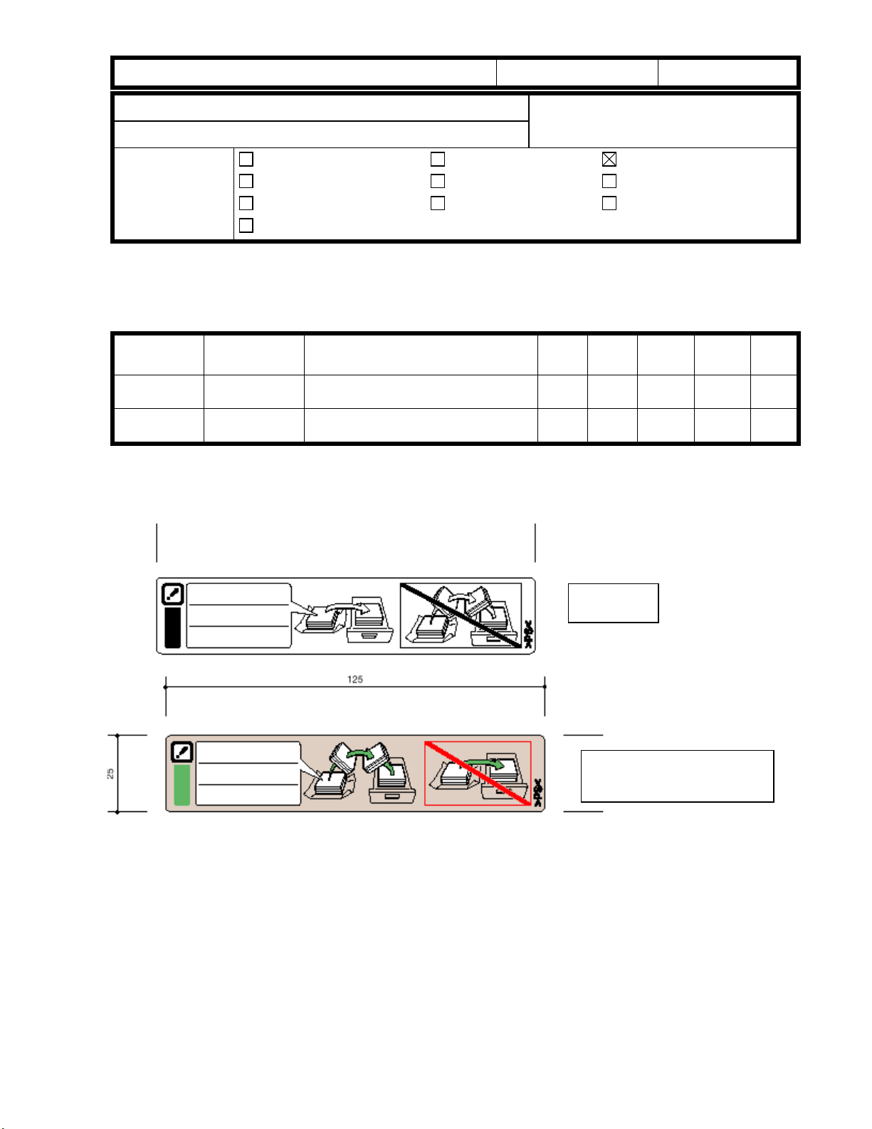
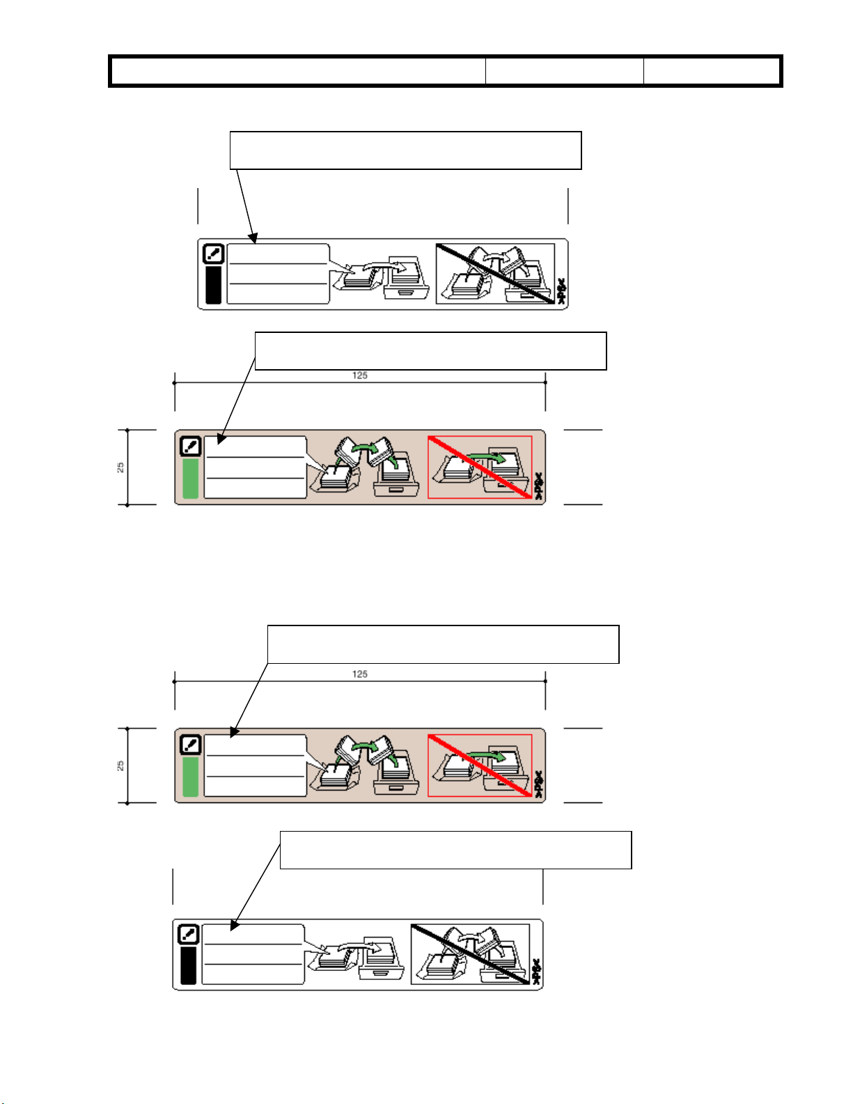
Face-up
Face-down
Decal - Paper Set Direction
The finisher stacking ability depends on the paper load orientation (face-up or face-down).
For some paper brands, face-up produces better stacking and for other brands, face down
is better. The above decal instructs customers on loading paper in order to prevent
unnecessary service calls. Therefore, please use this decal for operator training.
Page 2
echnical Bulletin
T
PAGE: 1/2
Model:
Subject:
From:
Bellini
Paper Guide Fence
Technical Services Dept., GTS Division
Classification:
Troubleshooting
Mechanical
Paper path
Other ( )
Part information
Electrical
Transmit/receive
Date:
03-Aug-00
Prepared by:
No.:
RA294028
H.K.
Action required
Service manual revision
Retrofit information
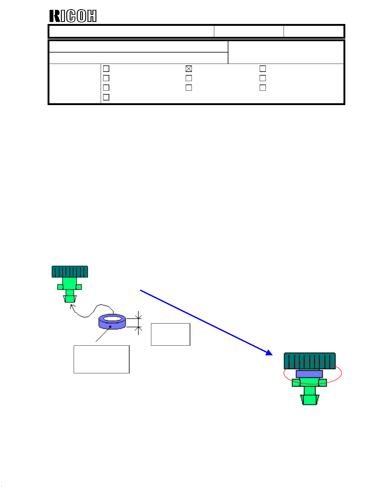
SYMPTOM
The end fence may detach due to vibration during transport.
CAUSE
The diameter of the holes in the paper guide fence for inserting the end fence was slightly
too large (i.e. Knob Screw with Rubber Tube). This is a side effect from the previous
modification (MB No.004).
SOLUTION
Final countermeasure on the production line
The diameter of the holes in the paper guide fence for inserting the end fence has been
decreased from 5.5 mm to 4.5 mm. Please refer to MB No. 006.
Temporary countermeasure on the production line
1.5 mm
Rubber ring
An extra rubber ring (1.5 mm) has been attached to the end fence to prevent it from
dropping. This rubber ring is made by cutting the Rubber Tube (B3032788) in the
production line to a thickness of 1.5 mm.
Page 3
echnical Bulletin
T
PAGE: 2/2
Model:
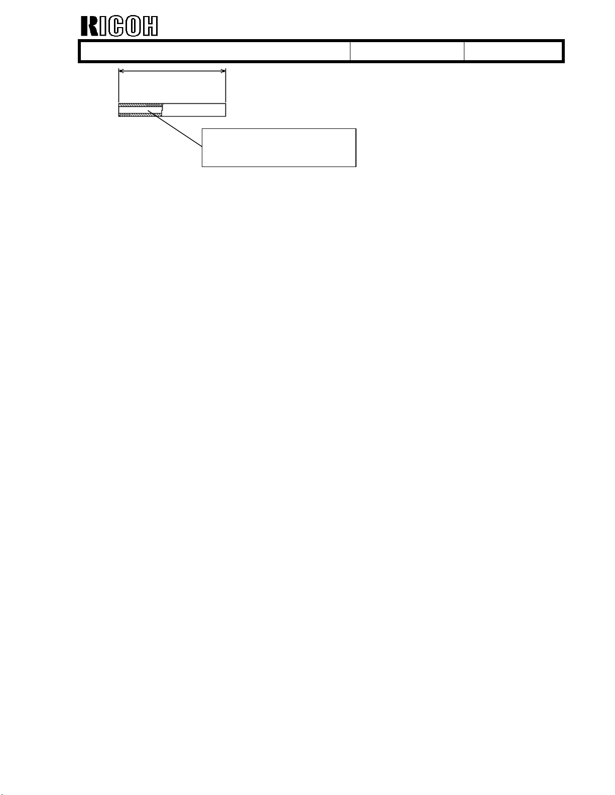
Note: When the new paper guide fence (B3032789: MB No.006) is installed in machines
with the extra rubber ring, it is not necessary to remove the rubber ring from the end fence.
Note:
We have applied the temporary solution at the factory from the same cut-in serial numbers
listed in MB No.004, except for the machines listed below. These units have already been
shipped and do not contain the countermeasures. However we estimate the occurrence
rate to be very low. Please reattach the end fence if it has come off during transport.
B30317 33 units:
Bellini
Rubber Tube - 2x4x33
B3032788
Date:
03-Aug-00
No.:
RA294028
H3900400592 to H3900400624
Page 4
!"#$% T
echnical Bulletin
PAGE: 2/3
Model:
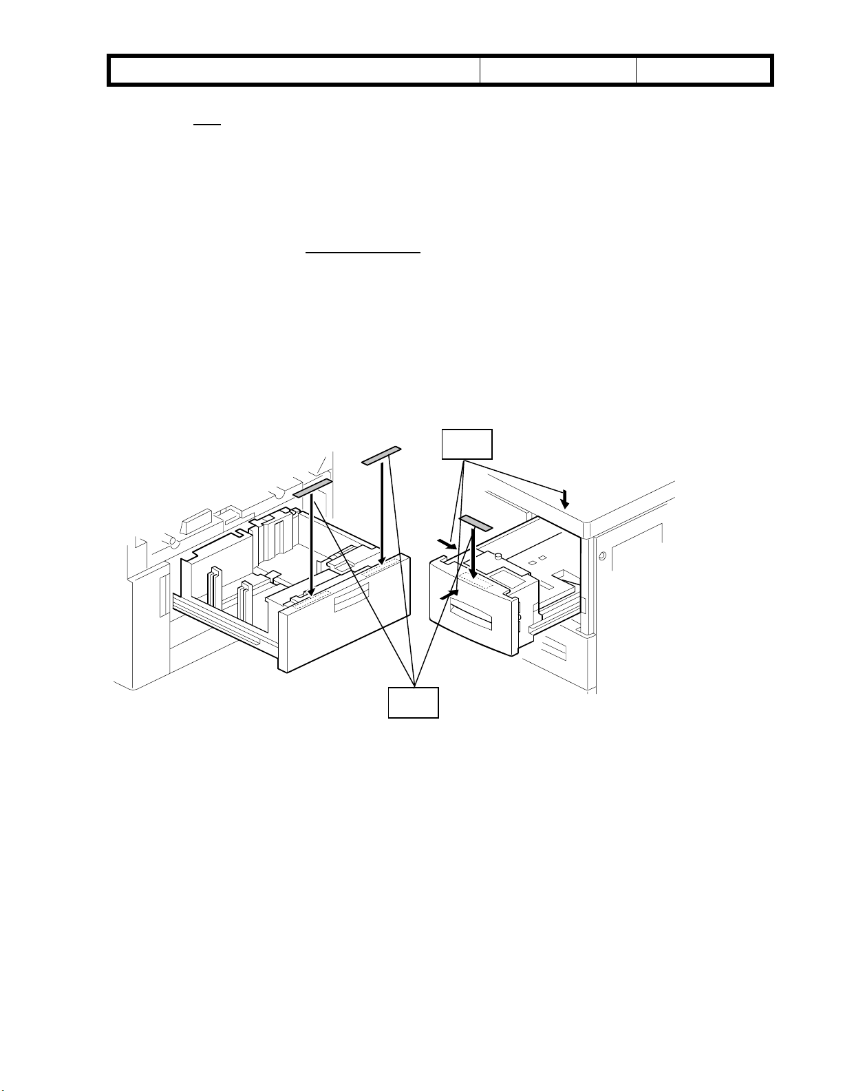
1. Using the mainframe paper trays, make more than 10 copies of a given paper brand
2. Compare the curl of the two bunches of paper by placing them on a flat surface.
3. If the face-down bunch shows less curling, write in the brand name on the face-down
4. Repeat steps 1 to 3 for all the brands of paper normally used by the customer.
5. Repeat steps 1 to 4 for LCT paper feed.
6. Attach the two decals [A] to the copier paper feed tray and LCT as shown.
Note: Two decals can be attached to each copier feed tray. However, there is only room
for one decal on the LCT. Therefore, attach the LCT decal with more brand names onto
the LCT itself. Attach the other to one of the areas labeled [B] below, whichever the
customer prefers.
Bellini
face-up and face-down. Try to use paper which is normally used by the customers.
label (and vice-versa).
Note: With the LCT, the paper is not inverted as it is when fed from the copier trays.
Therefore, the same brand of paper should yield opposite results. Please confirm this
when testing with the LCT and write in the brand name on the appropriate label.
B
Date:
26-May-00
No.:
RA294013
Example:
Copier feed:
Brand A curls less when facing up.
Brand B curls less when facing down.
LCT feed:
Brand A curls less when facing down.
Brand B curls less when facing up.
A
Page 5
!"#$% T
echnical Bulletin
PAGE: 3/3
Model:
Copier feed:
Bellini
Date:
[A] Write down brand names.
[B] Write down brand names.
26-May-00
No.:
RA294013
-------------------------------------------------------------------------------------------------------------------
LCT feed:
[A] Write down brand names.
[B] Write down brand names.
Page 6
echnical Bulletin
T
PAGE: 1/4
Model:
Subject:
From:
Bellini
LCT Tray Heater Kit
Technical Services Dept., GTS Division
Classification:
Troubleshooting
Mechanical
Paper path
Other ( )
Part information
Electrical
Transmit/receive
Date:
19-Jul-00
Prepared by:
No.:
RA294024
H.K.
Action required
Service manual revision
Retrofit information
Part Number of the Tray Heater Kit
The part number for the LCT Tray Heater Kit is not listed in the parts catalogue or service
manual. This kit can be ordered as a spare part.
The part number is as follows:
Old part
number
New part
Description Q’ty
number
A2949500 Tray Heater Kit - 230V 18W
1
This kit includes the following components:
Old part
number
New part
number
AX400053
Description Q’ty
Anti-Condensation Heater - 240V
18W
B3033841 Heater Cover
B3035324 Interface Harness
04514008B Philips Tapping Screw - M4x8
11050310 Harness Clamp - LWS-1S
11050292 Wire Saddle
2
1
1
6
2
1
Page 7

echnical Bulletin
T
PAGE: 2/4
Model:
Installation procedure for the Tray Heater Kit
1. Remove the LCT unit from the main copier and remove the LCT right cover.
2. Attach the two anti-condensation heaters [A and B] (2 screws each) to the LCT bottom
3. Attach the heater cover [C] (2 screws).
4. Attach the two cable clamps [D] to the LCT bottom plate as shown.
5. Lead the heater cables [E and F] through the cable clamps. Insert the connectors into
6. Connect the connectors [G and H] (interface cables) to the connectors that were just
Bellini
plate.
the connector bracket holes shown below.
inserted into the connector bracket holes (step 5).
G and H
D
Date:
19-Jul-00
E and F
No.:
RA294024
C
A and B
Page 8

echnical Bulletin
T
PAGE: 3/4
Model:
For steps 7-10, refer to the second illustration below.
Note: In accordance with safety standards, the connecting cable [A] must not be touching
the interface cable [B] when the optional LCT tray heaters are installed. Therefore, be sure
to perform steps 7-10 so that the cables remain separated.
7. Replace the wire saddle with the new one ([C] P/N: 11050292), which is included in the
8. Lead the connecting cable [A] as shown.
9. Connect the connector [D] of the interface cable to the mainframe interface.
10. Re-install all parts.
Bellini
optional tray heater kit.
[A]
Date:
[C]
19-Jul-00
No.:
RA294024
[D]
[B]
Page 9

echnical Bulletin
T
PAGE: 4/4
Model:
As mentioned on pg. 2-124 of the Service Manual, all anti-condensation heaters are
disconnected from the AC drive board before being shipped.
When the heater AC cable connector [A] is connected to the AC drive board, the transfer
anti-condensation (drum) heater will be turned on along with the other optional heaters
when the main switch is off.
main switch and unplug the copier power cord.
Bellini
Caution: Before plugging in the heater AC harness connector, be sure to turn off the
Date:
19-Jul-00
AC Drive Board
No.:
RA294024
Heater AC cable connector
Note: The heater AC cable connector is hung on the clamp under the AC drive board.
Page 10

echnical Bulletin
T
PAGE: 1/2
Model:
Subject:
From:
Bellini
Multi-feeding fom LCT
Technical Services Dept., GTS Division
Classification:
Troubleshooting
Mechanical
Paper path
Other ( )
Part information
Electrical
Transmit/receive
Date:
Prepared by:
SYMPTOM
Multi-feeding from the LCT.
CAUSE
The paper stack height is too high.
SOLUTION
Lower the paper stack height by shifting the tray lift sensor.
The procedure is as follows:
13-Oct-00
No.:
RA294035
S. Hizen
Action required
Service manual revision
Retrofit information
1. Remove the LCT right cover and inner cover and pull out the tray.
2. Remove the paper feed unit (see the service manual, page 6-62).
Paper Feed Unit
Paper Feed Unit
3. Remove the sensor bracket.
4. Remove the paper lift sensor.
Page 11

echnical Bulletin
T
PAGE: 2/2
Model:
5. Remove the cut-out from the bracket with a pair of wire cutters as shown in the
6. Install the paper lift sensor on the bracket.
7. Install the bracket as shown in the illustration. The gap between the bracket and the
Bellini
illustration.
unit is 2.5 mm (0.1 inch): If the customer uses thicker paper and non-feeding
occurs, shift the sensor bracket to reduce the gap.
Paper Feed Unit
2.5 mm (0.1 inch)
Date:
13-Oct-00
Lift Sensor Bracket
No.:
RA294035
Paper Lift Sensor
Page 12

echnical Bulletin
T
PAGE: 1/8
Model:
Subject:
From:
Bellini
LCT Guide Plate Kit
Technical Services Dept., GTS Division
Classification:
Troubleshooting
Mechanical
Paper path
Other ( )
Part information
Electrical
Transmit/receive
Date:
09-Nov-00
Prepared by:
No.:
RA294038
J. Mochizuki
Action required
Service manual revision
Retrofit information
To improve durability, the guide plate B3033645 and related parts have been modified. For
details please refer to MB303007. A2949902 (LCT Guide Plate Kit) has been registered as
a service part to supply the modified parts as a set.
This kit includes the following parts:
[A] B3033646 Guide Plate (1 pc)
[B] B3033680 Linkage Bracket (1 pc)
[C] B3033685 Collar (1 pc)
[D] AA060830 Tighten Spring (1 pc)
[E] 68032273 Stepped Screw (1 pc)
[F] B3031330 Decal - Misfeed
[A] to [E] of the above list have been used for mass production machines from the
following cut-in serial numbers. Please refer to MB303007.
B30314 L0680080001
B30317 H3900700001
B30324 L0680080029
B30326 4B30800001
B30327 H3900800146
B3031330 [F] includes three decals which will be stuck on the LCT inner cover from
November production.
[B]
[E]
[A]
[C]
[D]
Page 13

echnical Bulletin
T
PAGE: 2/8
Model:
Bellini
Guide plate installation procedure
1. Removal of Relay Transport Unit from LCT.
(1) Remove the stay from the LCT (4 screws).
4 screws
Date:
Stay
09-Nov-00
No.:
RA294038
Note: When removing the stay, be careful not to
deform the part shown in the illustration to
the left.
Page 14

echnical Bulletin
T
PAGE: 3/8
Model:
(2) Remove the harness around the relay transport unit from the harness clamps and board.
Bellini
[Front view of Relay Transport Unit] [Rear view of Relay Transport Unit]
Date:
09-Nov-00
No.:
RA294038
Remove harness from clamps.
Remove the connector on
the right.
Page 15

echnical Bulletin
T
PAGE: 4/8
Model:
(3) Remove the relay transport unit from the LCT (4 screws).
Note: As there are hooks, please lift and remove the relay transport unit.
Bellini
[Front view of Relay transport unit] [Rear view of Relay transport unit]
Date:
09-Nov-00
No.:
RA294038
Caution: Please be careful when handling the relay transport unit because there are sharp
edges on the unit.
Page 16

echnical Bulletin
T
PAGE: 5/8
Model:
Bellini
Date:
2. Removal of Old Parts on the Relay Transport Unit
(1) Remove the spring.
AA060817
Tighten Spring
09-Nov-00
No.:
RA294038
P. 4/7
(2) Remove the linkage bracket.
B3033681
Linkage Bracket
(3) Remove the Stepped Screw.
AA143444
Stepped Screw
Page 17

echnical Bulletin
T
PAGE: 6/8
Model:
(4) Remove the guide plate (2 stepped screws).
Bellini
[Front view of Relay Transport Unit] [Rear view of Relay Transport Unit]
Date:
09-Nov-00
No.:
RA294038
B3033645
Guide Plate
Page 18

echnical Bulletin
T
PAGE: 7/8
Model:
Bellini
Date:
09-Nov-00
No.:
RA294038
3. Installation of Countermeasure Parts on Relay Transport Unit
(1) Install the guide plate (B3033646) (2 stepped screws)
[Front view of Relay Transport Unit] [Rear view of Relay Transport Unit]
(2) Install the collar (B3033685) with the stepped screw (68032273)
Page 19

echnical Bulletin
T
PAGE: 8/8
Model:
(3) Install the linkage bracket by hooking it on the stepped screw.
(4) Lubricate with Silicone Grease G501 (52039502) at the parts in the photo.
Bellini
Sliding part with
stepped screw
Date:
09-Nov-00
B3033680
Linkage Bracket
Hook from Round part
No.:
RA294038
(5) Install the tighten spring (AA060380)
Sliding part
with frame
(6) Re-install the relay transport unit.
(7) Re-assemble the LCT.
 Loading...