

Page 1

LARGE CAPACITY TRAY
(Machine Code: A822)
Page 2

21 September 1998 SPECIFICATIONS
1. OVERALL MACHINE INFORMATION
1.1 SPECIFICATIONS
Copy Paper Size: A4 sideways
B5 Sideways
8
" x 11" sideways
1/2
Copy Paper Weight: 64 ~ 105 g/m2 16~24 lb
Power Source: DC 24 V, 5 V (from the copier)
Power Consumption: 48 W
Dimensions (W x D x H ): 403 x 529 x 608 mm (15.9" x 20.9" x 24.0")
Weight: 22.0 kg (48.5 lb)
Tray Capacity: 3,500 sheets (may vary slightly depending on
paper weight)
A822-1
Options
Page 3
MECHANICAL COMPONENT LAYOUT 21 September 1998
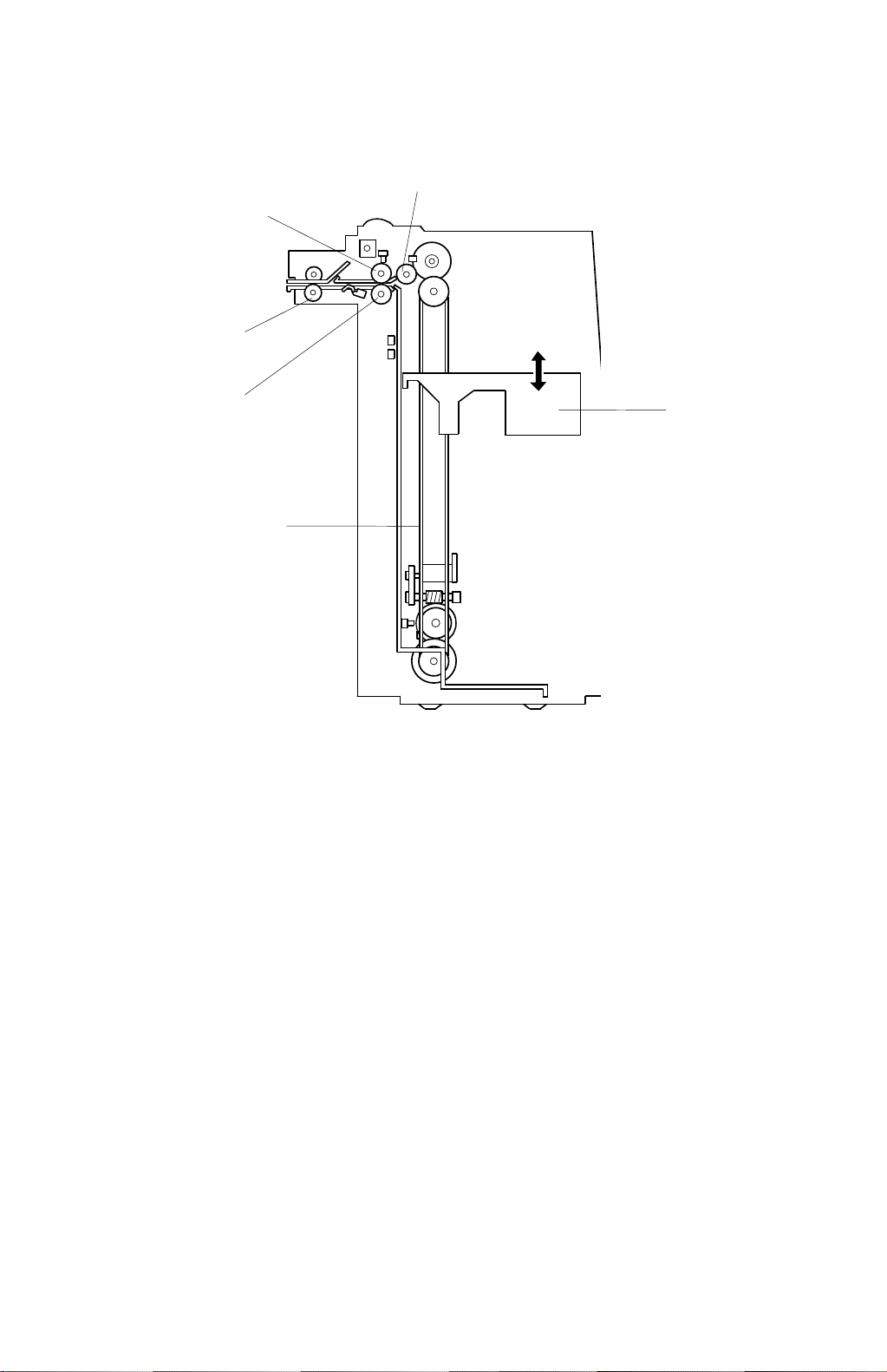
1.2 MECHANICAL COMPONENT LAYOUT
6
5
4
1. Bottom Plate
2. Tray Drive Belt
3
1
2
A822V500.WMF
3. Separation Roller
4. Transport Rollers
5. Feed Roller
6. Pick-up Roller
A822-2
Page 4

21 September 1998 ELECTRICAL COMPONENT DESCRIPTION
1.3 ELECTRICAL COMPONENT DESCRIPTION
Refer to the electrical component layout on the reverse side of the point-to-point
diagram for the location of the components using the symbols and index numbers.
Symbol Name Functi on I ndex No.
Motors
LCT Lifts and lowers the LCT bottom plate to
M1
M2 Feed Drives all feed and transport rollers. 5
Magnetic Clutches
MC1 Feed Starts the paper feed from the LCT. 4
Switches
LCT Cover 1
SW1
SW2 LCT Cover 2 Detects if the LCT cover is opened or not. 14
SW3
SW4
SW5
SW6 Tray Down Lowers the LCT bottom plate 16
LCT Cover 3 Cuts the power line for LCT when the LCT
Feed Unit Cover 1 Detects if the feed unit cover is opened or
Feed Unit Cover 2
bring the paper to the feed position and
allow loading of the paper.
Ensures that +24V can be passed to the
LCT motor whether the cover is open or
closed.
cover is opened.
not.
Cuts the power line for LCT when the LCT
cover is opened.
11
15
13
6
7
Solenoids
SOL1
Sensors
S1
S2
S3 Paper Position Detects the paper position. 10
S4
S5
S6 Lift Detects the correct paper feed height. 2
Pick-up
Paper End Informs the CPU that there is no paper on
Paper Near End Informs the CPU that about 60 sheets of
Tray Down Informs the CPU that the LCT bottom plate
Feed
Controls the up-down movement of the
pick-up roller.
the LCT bottom plate.
paper remain on the LCT bottom plate.
is in the lowest position.
Control the paper feed clutch off-on timing
and the pick-up solenoid off timing.
3
8
9
12
1
Options
A822-3
Page 5
MECHANICAL OPERATION 21 September 1998
2. DETAILED DESCRIPTION
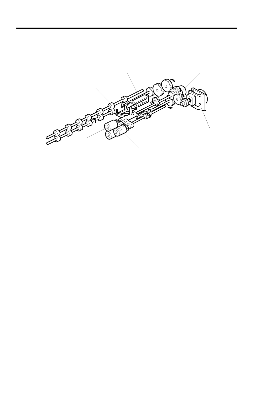
2.1 MECHANICAL OPERATION
[G]
[E]
[C]
[A]
[B]
The LCT uses an FRR feed system which uses three rollers. The pick-up [A],
separation [B] and feed [C] rollers are common with those of the by-pass feed unit
of the mainframe but different from those of the paper feed stations in the paper
tray unit.
A822D500.WMF
[F]
[D]
The LCT feed motor [D] drives the pick-up, separation, feed, and transport [E]
rollers.
The pick-up and feed rollers rotate only when the LCT feed clutch [F] activates.
Paper feeding starts when the LCT pick up solenoid [G] activates.
A822-4
Page 6

21 September 1998 PAPER LIFT MECHANISM
2.2 PAPER LIFT MECHANISM
[C]
[B]
[C]
[D]
[F]
[A]
A822D501.WMF
[E]
A822D505.WMF
The bottom plate [A] of the LCT is raised and lowered by the LCT motor [B] and the
drive belts [C]. When the main switch is on and the LCT cover is closed, the pickup solenoid [D] activates and the LCT motor [B] rotates clockwise to raise the
bottom plate until the top sheet pushes up the pick-up roller [E]. When the lift
sensor [F] is de-actuated, the copier CPU de-activates the LCT motor [B] and the
pick-up solenoid [D].
A822-5
Options
Page 7

PAPER LIFT MECHANISM 21 September 1998
[C]
[A]
[B]
A822D503.WMF
If the tray down switch [A] is pressed, or paper runs out, or a paper jam occurs in
the LCT, the LCT motor [B] rotates counterclockwise to lower the bottom plate.
However, it is not lowered all the way down at this time. When the paper position
sensor [C] activates, the LCT motor stops once. At this point, the bottom plate (or
the top sheet of paper) is positioned about 5 cm below the top. This gives enough
space for the customer to replenish about 500 sheets of paper. If the tray down
switch is then pressed again, the bottom plate moves down and stops once again
when the top sheet of paper just passes the paper position sensor. In this way, the
bottom plate is lowered 5 cm at each press of the tray down switch. This allows the
customer to replenish paper in convenient amounts and at the same position.
A822-6
Page 8

21 September 1998 PAPER END DETECTION
2.3 PAPER END DETECTION
[A]
[B]
A822D504.WMF
The paper end sensor [A] detects paper on the bottom plate. If there is paper on
the table, reflected light from the paper activates the paper end sensor. When the
paper runs out, the paper end sensor de-activates and informs the copier CPU of
the paper end condition.
The paper near end sensor [B] also detects the paper and the tray bottom plate. If
there is enough paper on the table, reflected light from the paper activates the
paper near end sensor. If less than about 60 sheets of paper remain, the paper
near end sensor de-activates because the black colored bottom plate does not
reflect the light from the sensor LED.
A822-7
Options
Page 9

EXTERIOR COVER REMOVAL 21 September 1998
3. REPLACEMENTS AND ADJUSTMENTS
3.1 EXTERIOR COVER REMOVAL
[D]
[B]
[F]
[G]
[E]
[C]
[A]
A822R500.WMF
3.1.1 FRONT COVER REMOVAL
1. Remove the right cover [A] (2 screws).
2. Remove the front cover [B] (3 screws).
3.1.2 REAR LOWER COVER REMOVAL
1. Open the LCT cover [C], then remove it (1 screw).
2. Remove the rear upper cover [D] (1 screw).
3. Remove the rear lower cover [E] (3 screws).
3.1.3 TOP COVER REMOVAL
1. Remove the right cover.
2. Remove the front cover.
3. Remove the hinge bracket [F] (1 screw).
4. Remove the top cover [G].
A822-8
Page 10

21 September 1998 PAPER FEED ROLLERS REPLACEMENT
3.2 PAPER FEED ROLLERS REPLACEMENT
[C]
[D]
[A]
[B]
1. Open the top cover [A].
2. Remove the pick-up roller [B] (1 snap ring).
3. Remove the feed roller [C] (1 snap ring).
4. Remove the separation roller [D] (1 snap ring).
NOTE:
Do not touch the surface of the rollers with oily hands.
The paper feed rollers used in the LCT are different from rollers used in
the 1st ~ 3rd feed units in the paper tray unit. They are not
interchangeable.
A822R501.WMF
A822-9
Options
Page 11

LCT FEED CLUTCH REMOVAL 21 September 1998
3.3 LCT FEED CLUTCH REMOVAL
[A]
[C]
[B]
[D]
[B]
A609R501.WMF
1. Remove the rear upper cover [A] (2 screws).
2. Disconnect the two connectors [B].
3. Remove the harness bracket [C] (2 screws).
4. Remove the bracket [D] with the LCT feed motor (3 screws).
5. Replace the LCT feed clutch [E] (2 Allen screws).
NOTE:
When installing the LCT feed clutch , set the stopper pin on the clutch in
the cut-out [F] on the bracket.
[E]
A822-10
Page 12

21 September 1998 UPPER COVER SWITCHES REMOVAL
3.4 UPPER COVER SWITCHES REMOVAL
[D]
[E]
[C]
[B]
[F]
[A]
[G]
A822R503.WMF
[B]
1. Shade the paper position and paper end sensors with a hand, then push the
tray down switch. (The tray go down to tray down sensor position.)
2. Turn off the main switch.
3. Remove the front cover. (Refer to Front Cover Removal, section 7.1.)
4. Remove the screws [A] securing the side fences [B].
5. Mark the original position of the screws [C] securing the bracket [D].
6. Remove the bracket [D] (2 screws).
7. Remove the paper end sensor [E] (1 connector, 1 screw).
NOTE:
8. Replace the upper cover switches [G] (7 connectors, 2 screws).
NOTE:
When removing the pape r end sensor, do not bend the stay [F].
When re-installing the switches, set the connectors correctly.
A822R504.WMF
Yellow
Blue
Green
Small white
Large white
9. Re-assemble and check copy quality.
A822-11
Options
Page 13

SIDE-TO-SIDE REGISTRATION ADJUSTMENT 21 September 1998
3.5 SIDE-TO-SIDE REGISTRATION ADJUSTMENT
A822R505.WMF
1. Follow the copier’s side-to-side registration adjustment.
Adjustment standard: less than 2 mm difference between the original and the
copy.
A822-12
Page 14

12
11
10
Lens
Verti cal
HP
S3S1
S3 S42
32132
12345
1514131211
-2-3-4-5-6-7-8
CN512-1
[0]
[5]
CC
V[5]
GND [0]
Guide
By-pass
Plate
Tal be
Position
S40M24S41
-B7
-B8
-B9
-B10
[5]
CC
V[5]
GND [0]
AA
CC
CC
[-24] V
[5] V
[5] V
-2-3-4-5-6-7-8
-B10
CN110-1
A
B
Erase Lamp
[12]
[ 0 ]
123
Drum
Potential
G
Position-1
1
6
9875432
10
[5]
CC
V[5]
SW6
321
12345
-B11
-B12
-B13
[5]
GND [0]
[12]
[0 ~ 5] Potential Sensor
E
C
D
(L4)
MM
Optics
Platen
3rd
Cover
[5]
Toner
Near
End
S10
CC
V[5]
[0] CGND
-9
GND [0]
1
-B14
-B15
[5]
[0] CGND
234
F
TH1
1112131415
-10
CC
V[5]
Thermistor [0-5]
[0]
[0/5] Erase Lamp Data
[5] LE
Lens
Scanner
Horizontal
HP
M3
S2
321
6543216543212
123456789
1
1413121110
-2-3-4-5-6-7-8
-11
-12
-13
-14
CN505-1
[5]
CC
AA
V[5]
→→→→→→→
V [24]
GND [0]
GND [0]
[24 0/24]
[24 0/24]
AABBAAB
[0] GND
[0 ~ 5] Fusing Thermistor
[0] GND
[ 5] Fusing Unit Set
[ 5] Power Relay
[ 5] Lead Edge
[ 5] Scan Start
TXD
-9-8-7-6-5-4-3-2-1
CN502-10
-2-3-4-5-6-7-8
CN102-1
[5] OE
[0/5] CLK
[0 ~ 12] TD Sensor VR
[12]
[0 ~ 5] TD Sensor
[0] CGND
[0] CGND
-9
-2-3-4-5-6-7-8
-10
CN114-1
7654321765432
5
1234567
4321321
S8
By-pass
Toner
Paper Size
Density
[24 0/24]
RXD
-9
Transfer Belt P ostioning SOL [ 24]
[0 ~ 5] Paper Size
M
NN
Optics
Lens
Cooling
Fan
M4
M20
1
1011121314
-9
-2
-10
-11
-12
CN517-1
[ 24]
AA
→
V [24]
PGND [0]
[24 0/24]
[24 0/24]
[24 0/24]
B
CC
[0] CGND
[12] +12 V
[5] V
[12] –12 V
→
[24 0/24]
B
V [24]
AAS2
→
[24 0/24]
B
→
[24 0/24]
A
V [24]
AAS2
A
→
[24 0/24]
Duplex Unit Set [t 5]
CGND [0]
CGND [0]
V[5]
V[5]
CGND [0]
CGND [0]
V[5]
V[5]
GND [0]
V [24]
V [24]
V [24]
V [24]
→
[24 0/24]
A
V [24]
→
[24 0/24]
A
→
[24 0/24]
B
V [24]
→
[24 0/24]
B
V [24]
ON [ 24]
Speed [H/24, L/0]
AGND [0]
Speed [H/0, L/24]
V [24]
V [24]
AAS1
AGND [0]
QL, PTL [ 5]
Relay [ 24]
PWM C
PWM G
PWM B
PWMT
T. F / B. C
T. F / B. V
GND [0]
CC
[5] V
[0 ~ 5] Drum Thermistor
[ 5] Drum Unit Set
[0] CGND
-11
-12
-13
-14
1
Pre-Transfer
Quenching
Charge Wire Cleaner
CC
CC
CC
CC
AA
t
[ 24]
AA
t
[ 24]
AA
t
[ 24]
AA
t
[ 24]
AA
AA
AA
t
AA
s
s
t
t
C. F/B
G. F/B
B. F/B
Density
[s 5]
[t 5]
[s 5]
[5]
t
t
Verti cal
987654321
AA
AA
V [24]
V [24]
[24 0/24]
[24 0/24]
AA
Not Used
[0] PGND
[24] V
-2-3-4-5-6
CN501-1
-2-3-4-5-6
-10
CN131-1
Cleaner Motor (+) [ 24]
Cleaner Motor (–) [ 24]
CC
[5] V
[0 ~ 5] ID Sensor
[5] LED
[0] CGND
-9
-10
14151617182223
14151617182223
65431
S9PCB9
Image
Density
N
OO
Origial
Legth
(LTVersion only)
S46
43213215432
123456789
987654321
11
10
-2-3-4-5-6-7-8
CN507-1
CC
CC
V[5]
V[5]
VR [0 ~ 5]
VR [0 ~ 5]
24
24
-9
[t 5]
V[5]CC
GND [0]
GND [0]
GND [0]
OUT [0 ~ 5]
OUT [0 ~ 5]
Optics Control
(PCB4)
CN130-1
-2
-3
-4
-5
-6
CN112-A1
A2
A3
A4
A5
A6
A7
A8
A9
A10
A11
A12
A13
A14
B1
B2
B3
B4
B5
B6
B7
B8
B9
B10
B11
B12
B13
B14
CN111-1
-2
-3
-4
-5
-6
CN105-1
-2
-3
-4
-5
-6
-7
CN116-1
-2
-3
-4
-5
-6
-7
-8
-9
-10
L5
L3
M8
CN606-10
O
131211
123456789
10
11
131211
-10
-11
CN520-1
→→→
Feed-back [0,5 0/5]
A14
A13
A12
A11
A10
A9
A8
A7
A6
A5
A4
A3
A2
A1
B14
B13
B12
B11
B10
B9
B8
B7
B6
B5
B4
B3
B2
B1
CN601-7
-6
-5
-4
-3
-2
-1
-9
-8
-7
-6
-5
-4
-3
-2
-1
13
13
CN661-3
-4
CN663-2
-1
CN662-2
-1
PP
APS
987654321
10
101112
987654321654321
10
-2-3-4-5-6-7-8
A10
A11
A12
A13
A14
B10
B11
B12
B13
B14
B15
CN661
GND [0]
PGND [0]
LED [ 5]
Sensor [ 5]
Motor ON [ 5]
Motor A [5 0/5]
Motor B [5 0/5]
A1
A2
A3
A4
A5
A6
3
A7
2
A8
1
A9
3
2
1
1
2
B2
2
B3
1
B4
2
B5
1
B6
2
B7
1
B8
2
B9
1
6
5
4
3
2
1
3
2
1
3
2
1
T.Belt P.SOL [ 24]
Transfer Feedback Current
Transfer FeedbackVoltage
Developement
Bias (PP2)
[ 24] Cleaner Motor (+)
[ 24] Cleaner Motor (–)
[ 24] QL/PTL
[0] PGND
Charge F/B Current
PWM C
-2-3-4-5-6-7-8
CN602-1
2345678
2345678
-1-2-5
-9-8-7
-11
-10
[ 24] V
AA
[ 24]
Charge
[24]
[ 24]
(PP1)
[ 24](+)
[ 24](–)
-9
-10
-11
-12
CC
CCP
V[5]
GND [0]
V[5]
+12 V [12]
MM
[38] V
[0] MGND
-2
CN516-1
A
B
8F
3
2
1
1
3
2
2
3
1
2
2
3
1
V [24]
AA
PGND [0]
PWMT
GND [0]
GND [0]
AA
Grid G/B Voltage
Grid ON
[0] GND
[24] V
-9
CN603-1
9
10
12
9
10
12
-6
-12
P
Platen
Lens
Cover
Horizontal
Position-2
HP
S43
S4S6 S5
32132165432
12345
-2-3-4-5-6
CN511-1
[5]
[5]
5V[5]
GND [0]
[ 38] Forward
[ 38] Reverse
CN515-2-4CN514-1
M1
Scanner
Registration
M17
Jogger HP
S38
Duplex Exit
S35
Duplex Paper End
S37
Duplex Entrance
S34
Duplex Feed
MC8
DuplexTransport
MC7
SOL
Duplex Positioning
13
SOL
Pressure Arm
14
Jogger
M19
Drum Cooling Fan
M22
Optics Board Cooling Fan
M21
CN605-1
6
CC
V[5]
GND [0]
→
[5] VCC
[0 0/5] A
-2-3-4-5-6
-2
-3
-4
-5
-6
-7
-8
CN681
13
-13
-12V [-12]
Drum Earth
-3
QQ
3rd ScannerAuto Image
M2
1
-2-3-4-5-6
CN506-1
AA
AA
→→→
→
V [24]
V [24]
[24 0/24]
[24 0/24]
[24 0/24]
[24 0/24]
AAB
B
→
[0 0/5] B
[0] GND
[ 5] Connector Set
[0] GND
[0] GND
-7
E
8765432
8765432
8765432
8765432
-8-7-6-5-4-3-2
T r ansfer
(PP3)
CN684
CN683
CN685
CN682-1
SOL
Transfer
Belt
Positioning
1
1
1
1
-1
[0]
[ 24]
CN682-2
1
Q
12
11
10
9
8
7
6
5
4
3
2
1
AABB
CCDD
EE
FF
GG
HH
II
A246/A247/A248/A822 Point to Point Diagram
F1
F2
CN3-1
6A
CN3-2
Fuse
801
802
803
804
805
N.C
RA
Lightening Arrestor
(LA1)
Capacity
Line
10 A
AC
6.3 A
V
AA1
6.3 A
V
AA2
6.3 A
V
AA3
6.3 A
V
AA4
1st Lift
1st Paper End
1st Pick-up
1st Paper Feed
1st Separation
Roller
1st Paper Feed
2nd Paper Feed
2nd Separation
Roller
2nd Paper Feed
N
C.B1
3
2
S14
1
3
2
S17
1
SOL
2
3
2
S11
1
SOL
6
MC
3
S12
SOL
7
MC
4
1
8
CN401-1
CN402-A1
-A10
-A11
-A12
-A13
-A14
[0] CGND
-2
[5]
-3
[5] V
CC
-4
[0] CGND
-5
[0 0/5]
→
-6
[5]
-7
[24] V
AA
-8
[ 24]
[5]
-A2
[0] CGND
-A3
CC
[5] V
-A4
[24] V
AA
-A5
[ 24]
-A6
[24] V
AA
-A7
[ 24]
-A8
[5]
-A9
[0] CGND
[5] V
CC
[24] V
AA
[ 24]
[24] V
AA
[ 24]
2
7
3
6
4
5
5
4
6
3
7
2
1
2
1
2
1
2
1
2
1
2
8
1
7
1
6
2
5
3
4
4
3
5
2
6
1
7
7
1
6
2
5
3
4
4
3
5
2
6
1
7
NF1
L
Paper Feed Control
(PCB5)
9
3
3rd Paper Feed
3rd Separation
Roller
3rd Paper Feed
2
S13
1
SOL
8
MC
5
2
1
2
1
8
2nd Lift
2nd Paper End
2nd Pick-up
3rd Lift
7
3rd Paper End
3rd Pick-up
2nd Paper Size
6
11D
3rd Tray Set
Right Tandem
Lock
Left Tandem
Lock
S15
S18
SOL
3
S16
S19
SOL
4
SW4
J
I
SW5
SOL
9
SOL
10
2
1
2
1
6
5
4
3
2
1
2
1
2
1
5
1st Lift Motor
2nd Lift Motor
3rd Lift Motor
M13
M14
M15
2
1
2
1
2
1
4
3
2nd Paper
Near End
3rd Paper
Near End
Toner Overflow
Toner Collection
3
2
Bottle Set
Toner Recycle
Toner Recycle
Rear Fence
Rear Fence Hp
Rear Fence
Return
Left Tandem
Paper
S22
S23
S45
SW3
M11
M18
S30
S31
S32
2
1
3
2
1
1
1
2
2
3
3
1
2
MC
2
2
1
4
3
2
1
2
1
3
2
1
3
2
1
3
2
1
1
AB
7
1
CN402-B8
-B10
-B11
-B12
-B13
-B14
CN403-A1
CN407-A1
CN411-1
CN412-A7
-A10
-A11
-A12
-B10
-B11
-B12
CN414-1
[5]
-B9
[0] CGND
[5] V
[24] V
[ 24]
[24] V
[ 24]
[0] CGND
-A2
[5]
-A3
[5] VCC
-A4
[0] CGND
-A5
→
[0 0/5]
-A6
[5] VCC
-A7
[24] VAA
-A8
[ 24]
-B1
[0] CGND
-B2
[5]
-B3
[5] VCC
-B4
[0] CGND
-B5
→
[0 0/5]
-B6
[5] VCC
-B7
[24] VAA
-B8
[ 24]
[0] CGND
-A2
[0/5 0] Size 5
-A3
[0/5 0] Size 4
-A4
[0/5 0] Size 3
-A5
[0/5 0] Size 2
-A6
[0/5 0] Size 1
-A7
[ 24]
-A8
[24] VAA
-B3
[0/5 0]
-B4
[0] CGND
-B5
[24]
-B6
[ 24]
-B7
[24]
-B8
[ 24]
[ 24] Up
-2
[ 24] Down
-5
[ 24] Up
-6
[ 24] Down
-7
[ 24] Up
-8
[ 24] Down
[0] CGND
-A8
[0 0/5]
→
-A9
[5] V
[0] CGND
[0 0/5]
→
[5] V
-B2
[0] CGND
-B3
[0 0/5]
→
-B4
[5] V
-B5
[0/5 0]
-B6
[0] CGND
-B7
[24] V
-B8
[ 24]
-B9
[0/5 0] Motor Set
[0] CGND
AA
V
[ 24]
[0/5 0] LeftTray Set
-2
[ 24] Forward
-3
[ 24] Reverse
-5
[0] CGND
-6
[0 0/5]
→
-7
[5] V
-8
[0] CGND
-9
[0] CGND
-10
[0 0/5]
→
-11
[5] V
-12
[0] GND
-13
[0/5 0]
-14
[5] V
CC
AA
AA
→
→
→
→
→
→
CC
CC
CC
→
AA
→
→
CC
CC
→
CC
Motor Speed [H/5, L/0]
Motor ON [t5]
Motor ON [ 5]
Lock [ 5]
RightTray S e t [0 /5 0]
6
2
5
3
4
4
3
5
2
6
1
7
1
8
2
7
3
6
4
5
5
4
6
3
7
2
8
1
1
8
2
7
3
6
4
5
5
4
6
3
7
2
8
1
1
6
2
5
3
4
4
3
5
2
6
1
2
1
1
11
2
10
3
9
4
8
5
7
6
6
7
5
8
4
9
3
10
2
11
1
1
1
2
2
3
3
5
5
6
6
7
7
8
8
9
9
10
10
11
11
12
12
13
13
14
14
15
15
CD
V [24]
AA
V[5]
CC
CGND [0]
AGND [0]
Lock [t5]
CGND [0]
V[5]
CC
AGND [0]
V [24]
AA
VAA [24]
AGND [0]
VCC [5]
CGND [0]
CGND [0]
[0 0/5]
→
CC
V[5]
CGND [0]
[0 0/5]
→
CC
V[5]
CGND [0]
[0 0/5]
→
CC
V[5]
CGND [0]
[0 0/5]
→
CC
V[5]
CGND [0]
CGND [0]
[0 0/5]
→
CC
V[5]
CGND [0]
[0 0/5]
→
CC
V[5]
CGND [0]
[0/5 0]
CC
V[5]
AA
V [24]
[ 24]
AA
V [24]
[ 24]
CN409-1
-2
-3
-4
8
CN408-1
6
-2
5
-3
4
-4
3
-5
2
-6
1
-7
7
1
CN416-1
2
-2
3
-3
4
-4
5
-5
6
-6
CN406-13
-12
-11
-10
-9
-8
-7
-6
-5
-4
-3
-2
-1
CN405-A11
-A10
-A9
-A8
-A7
-A6
-A5
-A4
-A3
-A2
-A1
-B11
-B10
-B9
-B8
-B7
-B6
-B5
-B4
-B3
-B2
-B1
1
-A10
-A11
-A12
-A13
-A14
-B10
-B11
-B12
-B13
-B14
1
2
2
-A2
-A3
-A4
-A5
-A6
-A7
-A8
-A9
-B1
-B2
-B3
-B4
-B5
-B6
-B7
-B8
-B9
3
3
4
4
5
5
6
6
7
7
8
8
9
9
10
10
11
11
12
12
13
13
16
16
17
17
18
18
19
19
20
20
21
21
22
22
23
23
24
24
25
25
26
26
27
27
28
28
29
29
30
30
CN410-A1
→
→
Paper Feed
M12
Toner
M10
Collection
CN104-A1
3
2
1
3
2
1
3
2
1
3
2
1
3
2
1
3
2
1
3
2
1
E
CN1-3
CN1-1
CN1-4
CN1-2
CN4-2
CN2-1
CN2-6
CN2-3
DC Power Supply Unit
(PCB3)
AA2CCMM
CGNDVV
CGND
AGNDVMGND
4
8
11
16
13112
11
12
11
12
A
CN103-1
N.C
-2
[0/5] Scan Input 0
-3
[0/5] Scan Input 1
-4
[0/5] Scan Input 2
-5
[0/5] Scan Input 3
-6
[0/5] Scan Input 4
-7
[0/5] Scan Input 5
-8
[0/5] Scan Input 6
-9
[0/5] Scan Input 7
-10
[0/5] Scan Output 0
-11
[0/5] Scan Output 1
-12
[0/5] Scan Output 2
-13
[0/5] Scan Output 3
[ 5] 3rd Lift Sensor
-A2
[ 5] 2nd Lift Sensor
-A3
Not Used
-A4
[ 5] 1st Lift Sensor
-A5
Not Used
-A6
Not Used
-A7
Not Used
-A8
Not Used
-A9
[0/5] Clock
-A10
[5] LE
-A11
[0] CGND
-B1
[24] VAAS1
-B2
[5] OE
-B3
-B4
[ 5] 3rd Paper Feed Clutch
-B5
[ 5] 2nd Paper Feed Clutch
-B6
Not Used
-B7
[ 5] 1st Paper Feed Clutch
-B8
[ 5] 3rd Paper Feed Sensor
-B9
[ 5] 2nd Paper Feed Sensor
-B10
Not Used
-B11
[ 5] 1st Paper Feed Sensor
Front Side Fence
S26
Open
Front Side Fence
S27
Close
Rear Side Fence
S28
Open
Front Side Fence
S29
Close
Right Tray Down
S24
1st Paper Near
S21
End
Right Tray Paper
S25
SOL
Front Side Fence
11
SOL
Rear Side Fence
12
2
2
1
1
5
5
4
4
9
9
2
33
787
8
22
22CN2-4
11
11
2
2
1
1
CN801-1
HOT
NEUTRAL
Front DoorSafety (SW2)
AA3CACBCCAA1
AGNDVV (+12V)
V (–12V)VVVAGND
510972
9105613246
9105
CA
AA3
CB
V [12]
V [24]
V [–12]
AGND [0]
AA4
6
14
6
13246
-2
-10
CN101-6
CN123-1
CC
V[5]
AA1
AA4
V [24]
V [24]
AGND [0]
AAS1
V [ 24]
CC
V
CGNDYAZB
-2-3-4-5-6
CN124-1
CSS1 CSS2 CSS3
-12
AAS2
V [ 24]
CGND
3
15
23478
23478
-3-4-7-8-9
CN101-2
CGND [0]
Signal Table
< >
s
t
[ ]
F
222
111166CN4-1
Optics Anti-Condensation Heater
2
2
1
1
Transfer Anti-Condensation Heater
Upper Tray Heater
LowerTray Heater
-3
Toner
Development
Supply
5
5
D
823451612345682
CB
9F8P
-5
-2-3-4-5-1-6-8
-11
CN107-7
CC
AA1
V [24]
GNDVCGNDYAZB
AC Line
DC Line
Puls
Signal Direction
Signal Direction
Active High
Active Low
Voltage
V[5]
AA3
V [24]
CC
-3-4-5
CN125-2
Lock [ 5]
CGND
CN126-2
AGND [0]
CGNDYAZB
-3-4-5
ON [ 5]
AGND [0]
CGND
G
4
3
2
1
Main
SW
L
(SW1)
5
6
E
F
9J
CN708-1
Transformer
(220/240V Verstion only)
By-pass
Toner
Bottle
Feed
M7MC1
1
2
1
-9
-10
-11
-12
-13
-14
-15
-16
CC
V[5]
AAS1
AAS2
V [24]
V [24]
Clutch ON [ 24]
AA4
[24] V
[0] AGND
CN120
CN128-1-2CN127-1
3
4
3
4
341
11
12
DF S6 S2 S1 SW6
DF Sorter Stapler Lift
AGND [0]
AA4
[24] V
[0] AGND
-2-3-4
AAS2
ON [ 5]
AGND [0]
Lock [ 5]
V [24]
Speed [H/5, L/0]
[t5] Sorter Detection
[0] CGND
-CN119
CN118-A1
131211
2
45612
[0]
-3
[100]
-5
[230]
M9M16M6
1234587123456872121214321
-2-3-4-5-6-7-8
CN106-1
CC
[ 24]
V[5]
AAS1
ON [ 5]
AGND [0]
AGND [0]
Lock [ 5]
V [24]
CC
CCCCCC
[0] CGND
[5]
[5] V
[0] CGND
[5]
[5] V
[0] CGND
[5]
-A2
-A3
-A7
-A8
-A9
-A4
-A5
76510984321123456789
3
Paper
Paper
Near
End
End
LCT (Option)
H
ACN1
-9
CC
V[5]
[0] CGND
-A12
MainFusing/Duplex
M5
-10
-A13
ACH2
-11
AGND [0]
[5] LED
-B13
131211
CN702-4
ACN2
Fusing Lamp N
[24] VAA
[t 24] Power Relay
-2
CN706-1
H
G
1L
-12
-13
ON [ 5]
Lock [ 5]
Direction [0: ccw, 5: cw]
[0] CGND
[ 5] LCT Connection
[0] CGND
[5]
-B12
-B11
-B10
10
(SW1)
LCT Cover
(SW4)
Feed Unit Cover
-3-2-1
Fusing Lamp H
CC
[5] V
-B9
987654321
3211238
1231098321
Tray
Down
-4-2-5-3-6
CN703-1
ACH
ACN
AAS1
V [24]
[5] V
[5] V
-A6
-A10
-A11
Tray Down
ACH1
AGND [0]
[5] SW
I
JJ
Main
RA1
-2
CN705-1
AA
V [24]
Exposure Lamp N
Exposure Lamp H
Power Relay [ 24]
AC Drive
(PCB2)
Key
Counter
Total Counter
(Option)
CO2
CO1
8G
11H
11H
D
F
H
E
C
G
-A2
-A3
-A4
-A5
-A6
-A7
-A8
CN113-A1
[ 24]
AA
AA
V [24]
V [24]
CGND [0]
CGND [0]
Main SW [ 24]
Front Door Safety [ 5]
Key Counter Comfirm [ 5]
Main Board (PCB1)
CC
CC
[5]
[0] CGND
[5] V
[5]
[0] CGND
[5] V
[5]
[0] CGND
-B8
-B7
-B6
-B5
-B4
-B3
-B2
-B1
101112
13
9
10
32112
3
S4 S5 S3
Paper
Feed
Position
J
L1
Exposure
TS1
314
2
2
1
G
2
1
314
2
-3-2-1
-1
CN701-4
CN704-2
Fusing Lamp 2: N
Fusing Lamp 2: H
Fusing Lamp 1: N
Fusing Lamp 1: H
Exposure Lamp N
Exposure Lamp H
Auto Response
Left
Operation
Panel
PCB7 S44
Operation
PCB6
Panel
Control
-6-5-4-3-2
CN101-7
-A9
-B1
-B2
-B3
-B4
-B5
-B6
-A10
[ 24]
AA
AA
V [24]
V [24]
Auto Response Sensor [ 5]
AAAAAA
[24] V
[ 24]
[24] V
[ 24]
[24] V
[0] AGND
-3-9-2
-11-4-12
CN117-5
511412392
511412392
76455764321
45763124567
21211234568
SOL
MC1
1
Feed
Pick-up
Feed
KK
CN503-1
CN707-8
-7
-6
-5
-4
-3
-2
-1
Verti cal
Transport
Right
Operation
Panel
LCD
PCB8
321
123456789
-1
131211
-A2
-B7
CC
V[5]
CC
[5] V
-1
1
1
M2 M1
-A3
-B8
-B9
-B10
CN108-A1
[5]
TXD
RXD
[5]
VCC
CGND [0]
CGND [0]
[0] AGND
[5] ON
[H/5, L/0] Speed
[ 5] Lock
[ 24] Tray Down
[ 24] Tray Up
[0] AGND
-6
-8
-14
-15-7-10
8
14
15710
16
8
14
15710
16
1
2
LCT
K
LL
Scanner
HP
L2
Fusing 2
Fusing 2
-2
-3
-4
-5
-6
-7
-8
By-pass
Paper
End
S20S39
987654321321213215432
10
-A4
-A5
[5]
CGND [0]
CGND [0]
CC
[5] V
[5]
-A2
CN109-A1
8765432
1234567
3213212
(SW5) Feed Unit Cover
LCT Cover
(SW2) (SW3)
S43
Exit
L2TF1
[ 24] Fusing Lamp 1
[ 24] Fusing Lamp 2
[ 24] Exp.Lamp
[0/5] LampV (–)
[0/5] LampV (+)
[0/5] Zero Cross (–)
[0/5] Zero Cross (+)
[24] V
AASW
By-pass
Pick-up
Registation
SOL
212
101112
-A6
-A7
-A8
-A9
-A10
[5]
CC
CC
V[5]
V[5]
CGND [0]
CC
[0] CGND
[5]
[0] CGND
[5] V
-A3
-A4
-A5
-A6
-A7
SOL
S36
16
Junction
Gate
Duplex
Transport
5
-A11
AA
V [24]
AA
[24] V
-A8
1
8
1
Fusing
Thermistor
By-pass
Feed
MC6
1
13
-A12
-A13
[ 24]
AA
V [24]
AA
[ 24]
[24] V
-A9
-A10
M23
-A14
[ 24]
[ 24]
TH2
8139
4
8139
4
-2-3-4
CN504-1
GND [0]
GND [0]
Fusing Unit Set [ 5]
Fusing Thermistor [0 ~ 5]
Exhaust
Fan
Guide
Plate
SOL
15
-B1
-B2
-B3
-B4
-B5
-B6
-A15
[t24]
[t24]
AA
AA
V [24]
V [24]
Speed H/L [H: 24/L: 0]
CC
CC
[5] V
[5]
[0] CGND
[5] V
[5]
[0] CGND
-B3
-B4
-B5
-B6
-B7
-B8
-B9
65432
1
1234556
32132
1
S33 S42 S7
Paper
Fusing
H
Guide
Exit
Duplex
Cooling
Fan
I9
[t24 ] Power Relay
L
Page 15

ELECTRICAL COMPONENT LAYOUT (A246/A247/A248/A822) 1/2
18
17
16
15
27
28
29
30
31
32
33
19
14
26
20
21
13
22
12
25
132
23
A246S500.WMF
24
4
5
92
93
75
6
74
7
8
38
9
46
39
40
45
91
10
76
77
78
79
80
81
102
103
104
105
82
83
118
90
89
88
87
A246S504.WMF
86
85
84
117
116
115
106
107
108
11
44
41
42
43
59 47
58
57
109
114
56
48
49
113
110
55
54
53
52
51
A246S502.WMF
50
101
94
95
111112
A246S506.WMF
119
120
96
121
60
100
61
122
34
35
36
A246S501.WMF
37
73
72
71
70
A246S503.WMF
68
97
123
62
63
64
65
99
A246S505.WMF
98
134
133
132
124
125
126
131
127
66
130
6769
129
128
A246S507.WMF
Page 16

ELECTRICAL COMPONENT LAYOUT (A246/A247/A248/A822) 2/2
Symbol Name Index No.P to P
Motors
M1 Scanner 5 Q8
M2 3rd Scanner 11 Q12
M3 Lens Horizontal 10 N12
M4 Lens Vertical 19 N12
M5 Main 120 I9
M6 Development 121 G9
M7 Toner Bottle 133 H9
M8 Charge Wire Cleaner 30 O1
M9 Fusing/Duplex 119 19
M10 Toner Collection 126 E7
M11 Toner Recycle 129 A3
M12 Paper Feed 94 E8
M13 1st Lift 95 A5
M14 2nd Lift 97 A4
M15 3rd Lift 98 A4
M16 By-pass Feed 124 H9
M17 Registration 123 Q7
M18 Rear Fence 55 A2
M19 Jogger 43 Q5
M20 Optics Cooling Fan 21 O12
M21 Optics Board Cooling Fan 118 Q5
M22 Drum Cooling Fan 106 Q5
M23 Duplex Cooling Fan 114 L1
M24 Exhaust Fan 104 L9
Magnetic Clutches
MC1 Toner Supply 122 H9
MC2 Toner Recycling 125 A3
MC3 1st Feed 75 A10
MC4 2nd Feed 79 A9
MC5 3rd Feed 82 A8
MC6 By-pass Feed 64 L99
MC7 Duplex Transport 39 Q6
MC8 Duplex Feed 38 Q6
Switches
SW1 Main 117 H11
SW2 Front Door Safety 115 G10
SW3 Toner Collection Bottle 128 A3
SW4 2nd Paper Size 100 A6
SW5 3rd Tray Set 99 A6
SW6 By-pass Table 62 M9
Solenoids
SOL1 Transfer Belt Positioning 34 Q2
SOL2 1st Pick-up 74 A11
SOL3 2nd Pick-up 78 A7
SOL4 3rd Pick-up 83 A7
SOL5 By-pass Pick-up 63 L9
SOL6 1st Separation Roller 76 A10
SOL7 2nd Separation Roller 81 A9
SOL8 3rd Separation Roller 84 A8
SOL9 Right Tandem Lock 96 A5
SOL10Left Tandem Lock 101 A5
SOL11Front Side Fence 54 E1
SOL12Rear Side Fence 49 E1
SOL13Duplex Positioning 40 Q6
SOL14Pressure Arm 44 Q5
SOL15Guide Plate 67 L9
SOL13Junction Gate 60 L1
Symbol Name Index No.P to P
Sensors
S1 Scanner HP 2 M12
S2 3 rd Scanner HP 9 M12
S3 Lens Vertical HP 7 M12
S4 Lens Horizontal HP 12 Q12
S5 APS 20 P12
S6 Auto Image Density 6 O12
S7 Drum Potential 31 M1
S8 Toner Density 37 N1
S9 Image Density 32 N1
S10 Toner Near End 36 M9
S11 1st Paper Feed 91 A10
S12 2nd Paper Feed 89 A10
S13 3rd Paper Feed 87 A9
S14 1st Lift 93 A11
S15 2nd Lift 80 A8
S16 3rd Lift 85 A7
S17 1st Paper End 92 A11
S18 2nd Paper End 90 A8
S19 3rd Paper End 88 A7
S20 By-pass Paper End 65 K9
S21 1st Paper Near End 53 E2
S22 2nd Paper Near End 77 A4
S23 3rd Paper Near End 86 A4
S24 Right Tray Down 52 E2
S25 Right Tray Paper 50 E1
S26 Front Side Fence Open 58 E3
S27 Front Side Fence Close 57 E3
S28 Rear Side Fence Open 48 E2
S29 Rear Side Fence Close 47 E2
S30 Rear Fence HP 59 A2
S31 Rear Fence Return 51 A1
S32 Left Tandem Paper 56 A1
S33 Paper Guide 61 L1
S34 Duplex Entrance 45 Q6
S35 Duplex Exit 42 Q7
S36 Duplex Transport 71 L1
S37 Duplex Paper End 46 Q6
S38 Jogger HP 41 Q7
S39 Vertical Transport 69 K9
S40 Guide Plate Position 68 M9
S41 Registration 70 L9
S42 Fusing Exit 72 L1
S43 Exit 73 K1
S44 Auto Response 17 J9
S45 Toner Overflow 127 A3
S46
S47
S48
Original Length
(LT version only)
Platen Cover Position 1
(Option)
Platen Cover Position 2
(Option)
8O12
3 M12
4Q12
Symbol Name Index No.P to P
PCBs
PCB1 Main 107 J6
PCB2 AC Drive 102 J10
PCB3 DC Power Supply 110 F10
PCB4 Optic Control 105 O10
PCB5 Paper Feed Control 109 C10
PCB6 Operation Panel Control 15 K9
PCB7 Left Operation Panel 18 J9
PCB8 Right Operation Panel 13 K9
PCB9 By-pass Paper Size 66 N1
Lamps
L1 Exposure Lamp 23 J12
L2 Fusing Lamps 24 K12
L3 Quenching 28 O1
L4 Erase 29 M2
L5 Pre-transfer 33 O1
Power Packs
PP1 Charge 27 P1
PP2 Development 108 P4
PP3 Transfer 35 Q2
Heaters
H1 Optic Anti-condensation 16 H12
H2 Transfer Anti-condensation 134 H12
H3 Upper Tray 131 G11
H4 Lower Tray 130 G11
Thermistors
TH1 Optic 1 M12
TH2 Fusing 25 L12
TH3
Others
CB1 Circuit Breaker 113 C12
CO1 Total Counter 132 J9
CO2 Key Counter - J9
LA1 Lightening Arrestor 116 E11
LCD1 LCD 14 K9
NF1 Noise Filter 112 D12
RA1 Main Power Relay 103 J12
TF1 Fusing Thermofuse 26 K12
TR1
TS1 Optics Thermoswitch 22 J2
Drum
(on the image density Sensor)
Transformer
(220 V version only)
(32) N1
111 H10
2
1
3
4
5
6
7
8
9
16
10
11
12
15
13
14
A822S500.WMF
Symbol Name Index No.P to P
Motors
M1 LCT 11 K1
M2 Feed 5 K1
Magnetic Clutch
MC1 Feed 4 K1
Switches
SW1 LCT Cover 1 15 I2
SW2 LCT Cover 2 14 K2
SW3 LCT Cover 3 13 K2
SW4 Feed Unit Cover 1 6 I1
SW5 Feed Unit Cover 2 7 K2
SW6 Tray Down 16 I1
Sensors
S1 Paper End 8 I1
S2 Paper Near End 9 I1
S3 Paper Position 10 J1
S4 Tray Down 12 J1
S5 Feed 1 J1
S6 Lift 2 H1
Solenoids
SOL1 Pick-up 3 J1
 Loading...