

Page 1

LCT
(Machine Code: A683)
Page 2

30 March, 1999 SPECIFICATIONS
1. OVERALL MACHINE INFORMATION
1.1 SPECIFICATIONS
Paper Size:
Paper Weight: 60 g/m2 ~ 105 g/m2, 16 lb ~ 28 lb
Tray Capacity: 1500 sheets (80 g/m2, 20lb)
Remaining Paper Detection: 5 steps (100%, 75%, 50%, 25%, Near end)
Power Source: 24 Vdc, 5 Vdc (from copier)
Power Consumption: 40 W
Weight: 17 kg
Size (W x D x H): 390 mm x 500 mm x 390 mm
A4 sideways/LT sideways
A683-1
Peripherals
Page 3
MECHANICAL COMPONENT LAYOUT 30 March, 1999
1.2 MECHANICAL COMPONENT LAYOUT
2
3 4 51
7
6
1. Relay Roller
2. Relay Sensor
3. Paper Feed Roller
4. Pick-up Roller
A683V500.WMF
5. Paper End Sensor
6. Paper Tray
7. Separation Roller
A683-2
Page 4
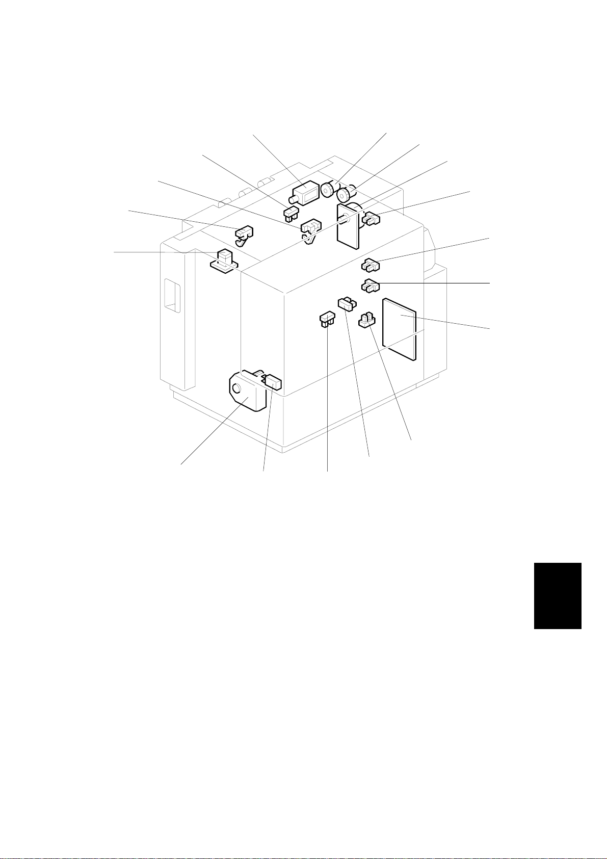
30 March, 1999 ELECTRICAL COMPONENT LAYOUT
1.3 ELECTRICAL COMPONENT LAYOUT
13
14
15
16
17
1
2
3
4
5
6
7
12
11
1. Relay Clutch
2. Paper Feed Clutch
3. LCT Motor
4. Paper Height 1 Sensor
5. Paper Height 2 Sensor
6. Paper Height 3 Sensor
7. Main Board
8. Side Fence Position Sensor
9. Lower Limit Sensor
8
9
10
A683V501.WMF
10. LCT Set Sensor
11. Tray Cover Switch
12. Lift Motor
13. Down Switch
14. Relay Sensor
15. Paper End Sensor
16. Lift Sensor
17. Pick-up Solenoid
Peripherals
A683-3
Page 5
ELECTRICAL COMPONENT DESCRIPTION 30 March, 1999
1.4 ELECTRICAL COMPONENT DESCRIPTION
Symbol Name Function Index No.
Motors
M1 LCT Drives all rollers. 3
M2 Lift Drives the paper tray up or down. 12
Sensors
S1
S2
S3
S4
S5 Paper Height 1 Detects the paper height. 4
S6 Paper Height 2 Detects the paper height. 5
S7 Paper Height 3 Detects the paper height. 6
S8
S9
Paper End Informs the copier when the paper has run
out.
Relay Detects the copy paper coming to the relay
roller and checks for misfeeds.
Lift
Lower Limit
LCT Set Detects whether the LCT is correctly set or
Side Fence
Position
Detects when the paper is at the correct
paper feed height.
Detects when the tray is completely lowered,
to stop the LCT motor.
not.
Detects when the side fence is set at the A4
size position.
15
14
16
9
10
8
Switches
SW1
SW2
Solenoids
SOL1
Magnetic Clutches
MC1 Paper Feed Drives the paper feed roller. 2
MC2 Relay Drives the relay roller. 1
PCBs
PCB1
Tray Cover
Down Lowers the LCT bottom plate if pressed by
Pick-up
Main Controls the LCT and communicates with the
Stops the LCT lift motor when the tray cover
is opened.
the user.
Controls up-down movement of the pick-up
roller.
copier.
11
13
17
7
A683-4
Page 6

30 March, 1999 DRIVE LAYOUT
1.5 DRIVE LAYOUT
321
10
4
9
8
5
7
1. Relay Clutch
2. Paper Feed Clutch
3. LCT Motor
4. Tray Bottom Plate
5. Pick-up Roller
6
A683V502.WMF
6. Tray Drive Belts
7. Lift Motor
8. Separation Roller
9. Paper Feed Roller
10. Relay Roller
Peripherals
A683-5
Page 7

PAPER FEED MECHANISM 30 March, 1999
2. DETAILED DESCRIPTIONS
2.1 PAPER FEED MECHANISM
[D]
[A]
[B]
[C]
A683D500.WMF
This machine uses the FRR paper feed system (paper feed roll er [A], separ ati o n
roller [B], pick-up roller [C]).
When the start key is pressed, the pick-up solenoid [D] energizes and the pick-up
roller touches the paper.
A683-6
Page 8

30 March, 1999 TRAY LIFT AND PAPER HEIGHT DETECTION MECHANISM
2.2 TRAY LIFT AND PAPER HEIGHT DETECTION MECHANISM
[D]
[F]
[B]
[G]
[A]
[H]
[C] [E]
A683D501.WMF
The lift motor [A] controls the vertical position of the tray bottom plate [B] through
gears and timing belts [C].
Tray lifting conditions
When the tray lift sensor [D] turns off in the following conditions, the tray lift motor
raises the tray bottom plate until the tray lift sensor [D] turns on again.
• Just after the main switch is turned on
• During copying
• Just after the tray cover is closed
• Just after leaving the energy saving mode
Tray lowering conditions
In the following conditions, the lift motor lowers the tray bottom plate until the lower
limit [E] sensor turns on.
• Just after the paper end sensor turns on
• Just after the down switch is pressed by the user
The amount of the paper in the tray is detected by combination of high/low outputs
from three sensors (paper height sensor 1 [F], 2 [G], and 3 [H].)
Amount of paper
Near end On (High) Off (Low) Off (Low)
25% Off (Low) On (High) Off (Low)
50% Off (Low) On (High) On (High)
75% Off (Low) Off (Low) On (High)
100% Off (Low) Off (Low) Off (Low)
Paper Height
Sensor 1
A683-7
Paper Height
Sensor 2
Paper Height
Sensor 3
Peripherals
Page 9

TRAY UNIT SLIDE MECHANISM 30 March, 1999
2.3 TRAY UNIT SLIDE MECHANISM
[B]
[A]
A683D502.WMF
When there is a paper jam between the copier and the LCT, the user releases the
lock lever [A] and can slide the LCT away from the copier to remove the jammed
paper.
When sliding the LCT back into position, the LCT is secure d against the co pier in
the correct position by the docking pins [B] on the LCT.
A683-8
Page 10

30 March, 1999 DIP SWITCHES
3. SERVICE TABLES
3.1 DIP SWITCHES
DPS101
12345678
10000000Default
10000001Free run
NOTE: 1) Do not use any other settings.
2) To do the free run, proceed as follows:
1. Remove the paper from the LCT (this is because the machine has no
jam detection).
2. Set DPS101 for the free run as shown above.
3. Turn the main switch off, wait a few seconds, then switch back on.
4. Press SW101 to start the free run.
5. To stop the free run, press SW102.
3.2 TEST POINTS
No. Label Monitored Signal
TP100 (24 V) +24 V
TP101 (GND) Ground
TP103 (TXD) TXD to the copier
TP104 (RXD) RXD from the copier
TP105 (5 V) +5 V
TP106 (GND) Ground
Description
3.3 SWITCHES
No. Function
SW101 Starts the free run
SW102 Stops the free run
3.4 FUSES
No. Function
FU101 Protects the 24 V line.
Peripherals
A683-9
Page 11

COVER REPLACEMENT 30 March, 1999
4. REPLACEMENT AND ADJUSTMENT
4.1 COVER REPLACEMENT
[D]
[F]
[B]
[A]
Tray Cover
1. Remove the tray cover [A] (1 snap ring).
Front Cover
1. Remove the front cover [B] (2 screws).
Rear Cover
1. Remove the tray cover.
2. Remove the cover hinge [C] (2 screws).
3. Remove the rear cover [D] (3 screws).
Right Lower Cover
[E]
[C]
A683R500.WMF
1. Remove the right lower cover [E] (2 screws).
Upper Cover
1. Remove the front cover.
2. Remove the rear cover.
3. Remove the upper cover [F].
A683-10
Page 12

30 March, 1999 ROLLER REPLACEMENT
4.2 ROLLER REPLACEMENT
4.2.1 PAPER FEED, SEPARATION, AND PICK-UP ROLLERS
[B]
[A]
[C]
[D]
A683R501.WMF
1. Push the down switch to lower the tray bottom plate until it reaches its lowest
position.
2. Open the tray cover.
Pick-up Roller
3. Replace the pick-up roller [A] (1 snap ring).
Paper Feed Roller
3. Replace the paper feed roller [B] (1 snap ring).
Separation Roller
3. Remove the guide plate [C] (2 screws).
Peripherals
4. Replace the separation roller [D] (1 snap ring).
A683-11
Page 13

TRAY LIFT AND PAPER END SENSOR REPLACEMENT 30 March, 1999
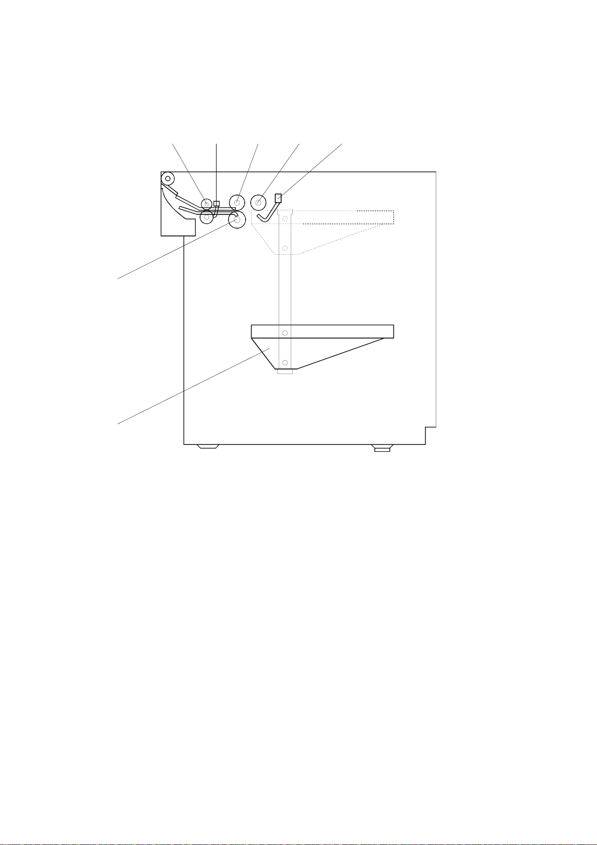
4.3 TRAY LIFT AND PAPER END SENSOR REPLACEMENT
[A]
[C]
[B]
1. Remove the front and rear cover.
2. Remove the upper cover.
3. Remove the sensor bracket [A] (1 screw).
Tray Lift Sensor
3. Replace the tray lift sensor [B] (1 connector).
Paper End Sensor
3. Replace the paper end sensor [C] (1 connector).
A683R502.WMF
A683-12
Page 14

30 March, 1999 RELAY SENSOR REPLACEMENT
4.4 RELAY SENSOR REPLACEMENT
[B]
[A]
[C]
A683R503.WMF
1. Pull out the LCT.
2. Remove the joint guide [A] (4 screws).
3. Remove the sensor bracket [B] (1 screw).
4. Replace the relay sensor [C] (1 connector).
Peripherals
A683-13
Page 15

SIDE FENCE POSITION CHANGE 30 March, 1999
4.5 SIDE FENCE POSITION CHANGE
[A]
A4
LT
[B]
A4 →→→→ LT
A683R504.WMF
1. Push the down switch to lower the tray bottom plate until it reaches its lowest
position.
2. Remove the tray cover.
3. Remove the front and rear side fences [A, B] (1 screw each).
4. Install the side fences in the correct position.
A683-14
 Loading...