

Page 1

LARGE CAPACITY TRAY
(Machine Code: A609)
Page 2

15 July 1996 SPECIFICATIONS
1. SPECIFICATIONS
Copy Paper Size: A4 sideways
B5 Sideways
1/2
8
" x 11" sideways
2
Copy Paper Weight: 64 ~ 105 g/m
Power Source: DC24 V, 5V (from the copier)
Power Consumption: 48 W
Dimensions (W x D x H ): 403 x 529 x 608 mm
(15.9" x 20.9" x 24.0")
Weight: 19.8 kg (43.7 lb)
Tray Capacity: 3,500 sheets (may vary slightly depending on
paper weight)
16~24 lb
Large
Capacity Tray
1
Page 3
MECHANICAL COMPONENT LAYOUT 15 July 1996
2. MECHANICAL COMPONENT LAYOUT
6
5
4
3
1
2
A609V500.wmf
1. Bottom Plate
2. Tray Drive Belt
3. Separation Roller
4. Transport Rollers
5. Feed Roller
6. Pick-up Roller
2
Page 4

15 July 1996 ELECTRICAL COMPONENT DESCRIPTION
3. ELECTRICAL COMPONENT DESCRIPTION
Symbol Name Function Index No.
Sensors
S1
S2
S3 Paper Position Detects the paper pos i tion. L4
S4
S5
S6 Lift Detects the correct paper feed height . L10
Switches
SW1
SW2
SW3 Tray Down Lowers the LCT bottom plat e. L8
Paper End Informs the CPU that th er e i s no
paper on the LCT bottom plate.
Paper Near End Informs the CPU that about 60 sheets
of paper remain on the LCT bottom
plate.
Tray Down Informs the CPU that the LCT bottom
plate is in the lowe st position.
Feed Controls the paper feed clutch off-on
timing and the pick-up solenoid off
timing.
Feed Unit Cove r Detects if the fee d uni t cover is open
or not.
There are two sensor s.
Note:
LCT Cover Detects if the LCT cove r is open or
not.
There are three se nsors.
Note:
L2
L3
L6
L9
L1
L7
Motors
LCT Lifts and lowers the LCT bottom plate
M1
M2 Feed Drives all feed and t ransport rollers. L13
Others
SOL1
MC1 Feed Starts paper feed from the L CT. L12
Pick-up Controls the up-down movemen t of
to bring paper to t he f eed position and
allow loading of the paper.
the pick-up rol l er .
L5
L11
Large
Capacity Tray
3
Page 5
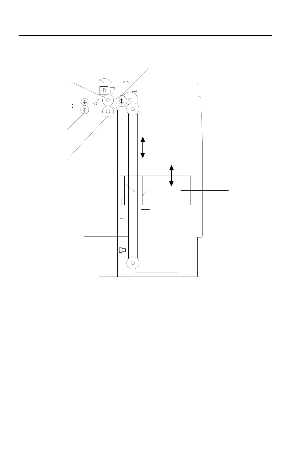
MECHANICAL OPERATION 15 July 1996
4. MECHANICAL OPERATION
[G]
[F]
[E]
[D]
[C]
[A]
[B]
A609D500.wmf
The LCT uses an FRR feed system which uses three rollers.
The pick-up [A], separation [B] and feed [C] rollers are common with those of
the by-pass feed unit of the mainframe but different from those of the paper
feed stations in the paper tray unit.
The LCT feed motor [D] drives the pick-up, separation, feed, and transport [E]
rollers.
The pick-up and feed rollers rotate only when the LCT feed clutch [F]
activates.
Paper feeding starts when the LCT pick up solenoid [G] activates.
4
Page 6
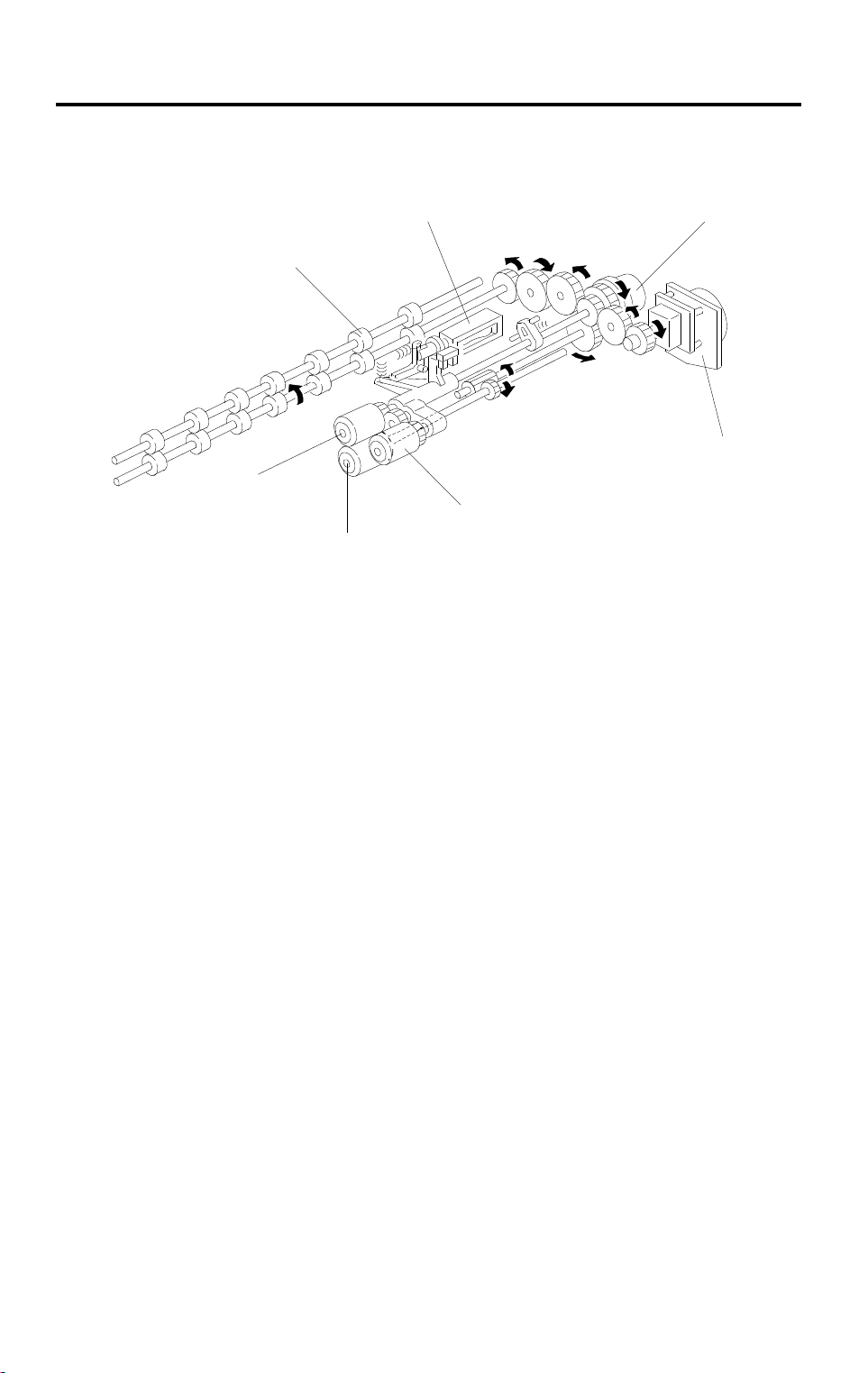
15 July 1996 PAPER LIFT MECHANISM
5. PAPER LIFT MECHANISM
[C]
[B]
[C]
[D]
[A]
[F]
A609D501.wmf
[E]
A609D502.wmf
The bottom plate [A] of the LCT is raised and lowered by the LCT motor [B]
and the drive belts [C]. When the main switch is on and the LCT cover is
closed, the pick-up solenoid [D] activates and the LCT motor [B] rotates
clockwise to raise the bottom plate until the top sheet pushes up the pick-up
roller [E]. When the lift sensor [F] is de-actuated, the copier CPU de-activates
the LCT motor [B] and the pick-up solenoid [D].
Large
Capacity Tray
5
Page 7
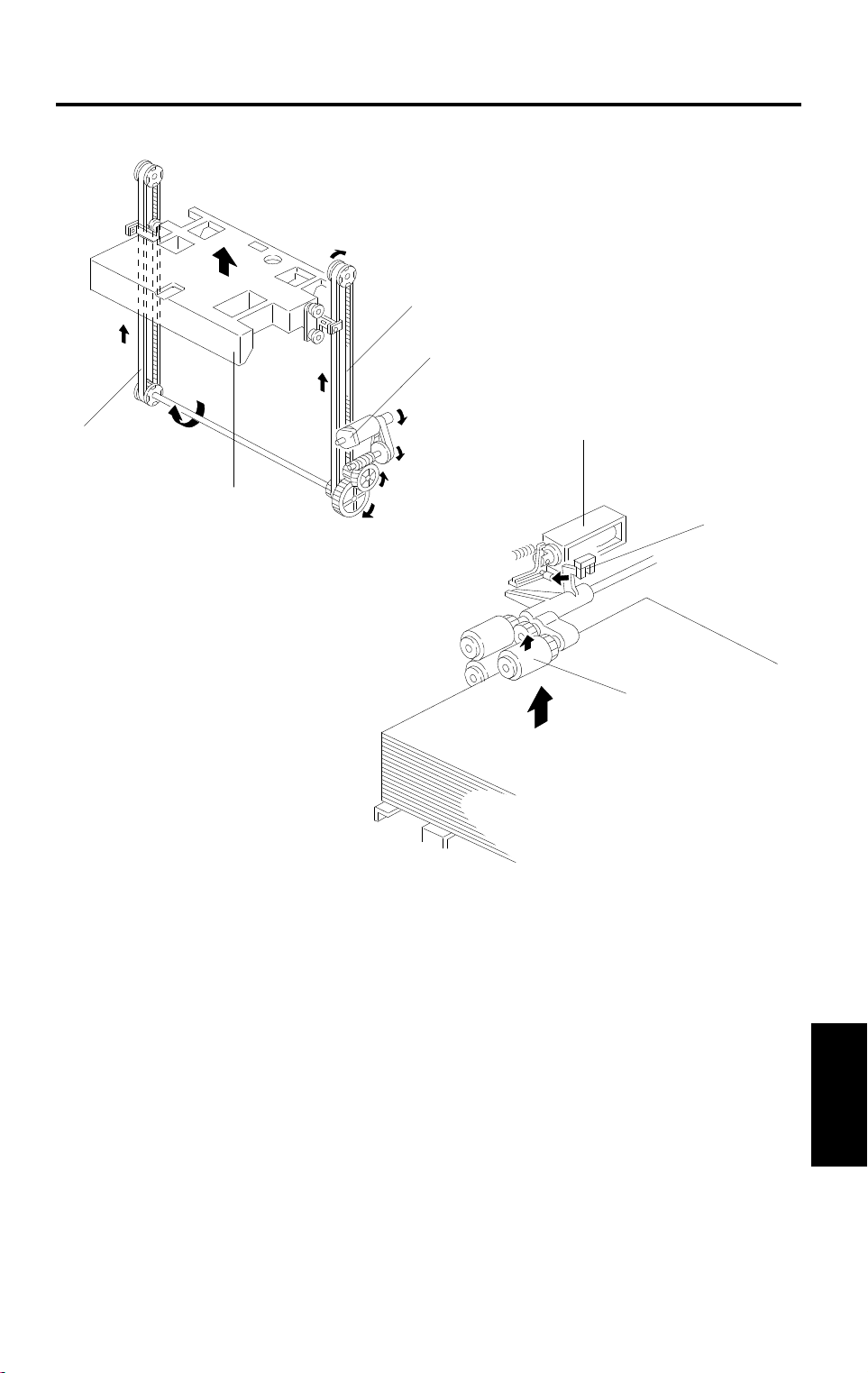
PAPER LIFT MECHANISM 15 July 1996
[C]
[A]
[B]
A609D503.wmf
If the tray down switch [A] is pressed, or paper runs out, or a paper jam
occurs in the LCT, the LCT motor [B] rotates counterclockwise to lower the
bottom plate. However, it is not lowered all the way down at this time. When
the paper position sensor [C] activates, the LCT motor stops once. At this
point, the bottom plate (or the top sheet of paper) is positioned about 5 cm
below the top. This gives enough space for the customer to replenish about
500 sheets of paper.
If the tray down switch is then pressed again, the bottom plate moves down
and stops once again when the top sheet of paper just passes the paper
position sensor. In this way, the bottom plate is lowered 5 cm at each press
of the tray down switch. This allows the customer to replenish paper in
convenient amounts and at the same position.
6
Page 8
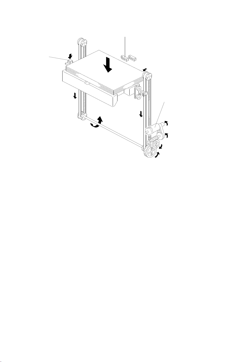
15 July 1996 PAPER END DETECTION
6. PAPER END DETECTION
[A]
[B]
A609D504.wmf
The paper end sensor [A] detects paper on the bottom plate. If there is paper
on the table, reflected light from the paper activates the paper end sensor.
When the paper runs out, the paper end sensor de-activates and informs the
copier CPU of the paper end condition.
The paper near end sensor [B] also detects the paper and the tray bottom
plate. If there is enough paper on the table, reflected light from the paper
activates the paper near end sensor.
If less than about 60 sheets of paper remain, the paper near end sensor
de-activates because the black colored bottom plate does not reflect the light
from the sensor LED.
Large
Capacity Tray
7
Page 9

REPLACEMENTS AND ADJUSTMENTS 15 July 1996
7. REPLACEMENTS AND ADJUSTMENTS
7.1 PAPER FEED ROLLERS RE PL ACEME NT
[C]
[D]
1. Open the top cover [A].
2. Remove the pick-up roller [B] (1 snap ring).
[A]
[A]
A609R500.wmf
3. Remove the feed roller [C] (1 snap ring).
4. Remove the separation roller [D] (1 snap ring).
NOTE:
Do not touch the surface of the rollers with oily hands.
The paper feed rollers used in the LCT are different from rollers
used in the 1st ~ 3rd feed units in the paper tray unit.
8
Page 10

15 July 1996 REPLACEMENTS AND ADJUSTMENTS
7.2 LCT FEED CLUTCH REMOVAL
[A]
[C]
[B]
[D]
[B]
A609R501.wmf
1. Remove the rear upper cover [A] (2 screws).
2. Disconnect the two connectors [B].
3. Remove the harness bracket [C] (2 screws).
4. Remove the bracket [D] with the LCT feed motor (3 screws).
5. Replace the LCT feed clutch [E] (2 Allen screws).
NOTE:
When installing the LCT feed clutch, set the stopper pin on the
clutch in the cut-out [F] on the bracket.
[E]
Large
Capacity Tray
9
Page 11

REPLACEMENTS AND ADJUSTMENTS 15 July 1996
7.3 UPPER COVER SWITCHES
[A]
[B]
A609R502.wmf
❶
1. Remove the right cover [A].
2. Remove the front cover [B].
3. Remove the upper cover switches [C].
❷
[C]
❸
❹
❺
A609R503.wmf
NOTE:
When installing the switches, set the connectors correctly.
❶ Yellow
❷ Blue
❸ Green
❹ Small white
❺ Large white
10
Page 12

15 July 1996 REPLACEMENTS AND ADJUSTMENTS
7.4 SIDE-TO-SIDE REGISTRATION ADJUSTMENT
[B]
[A]
A609R504.wmf
- Rough Adjustment -
1. Loosen the two screws [A] fixing the stay [B].
2. Move the stay position to change the side-to-side paper position.
- Fine Adjustment -
1. Enter SP mode (refer to the service program access procedure) and
access the side to side adjustment mode ( SP Adjustment - PAGE
4).
2. Adjust side to side registration by changing the SP mode data.
NOTE:
Copies can be made in SP mode. Touch the "Copy in SP" key to
select the paper feed station.
Adjustment standard: less than ±2 mm difference between the original and
the copy.
Large
11
Capacity Tray
Page 13

15 July 1996 LCT (A609)
7. LCT (A609)
7.1 ACCESSORY CHECK
Check the accessories in the box according to the following list:
Description Q’ty
1. LCT feed unit ............................................................................ 1
2. Small cover - left cover.............................................................. 1
3. Philips pan head screw - M4 x 6 ............................................... 3
4. Philips pan head screw - M4 x 16 ............................................. 3
5. Tapping screw - M4 x 8 ............................................................. 1
Installation
3-41
Page 14

LCT (A609) 15 July 1996
7.2 INSTALLATION PROCEDURE
[E]
[A]
A609I500.wmf
[B]
[B]
[C]
A609I501.wmf
[D]
[F]
CAUTION
A609I502.wmf
A609I503.wmf
Unplug the copier power cord before star ting the follo wing procedure.
1. Remove the four strips of tape [A].
2. Open the LCT cover [B] and remove the tape [C] fixing the paper trailing
edge stopper.
3. Remove the tray cushion [D] secured with three strips of tape [E].
4. Remove the LCT connector [F] (3 screws).
3-42
Page 15

15 July 1996 LCT (A609)
[A]
[D]
[E]
[B]
[C]
[C]
A609I504.wmf
[H]
Installation
[F]
A609I505.wmf
[G]
A609I506.wmf
5. Open the by-pass table [A] approximately 45 degrees and push the
stoppers [B] of the feed unit cover [C] by using a small flat head screw
driver [D], then remove the feed unit cover.
6. Remove the harness cover [E].
7. Remove the shipping retainers [F].
8. Install the LCT feed unit [G] to the copier (3 screws - M 4 x 6).
CAUTION
Do not pinch the harness [H] located below the by-pass table.
3-43
Page 16

LCT (A609) 15 July 1996
[D]
[C]
[D]
[B]
[A]
A609I507.wmf
[G]
[E]
[F]
A609I508.wmf
9. Install the LCT connector [A] to the copier.
1) Remove the three caps [B].
2) Set the two pins [C] of the LCT connector into the two holes [D] on the
LCT feed unit.
3) Install the LCT connector to the copier (3 screws - M4 x 16).
10. Remove the screw fixing the upper cover hinge [E] then slide and remove
the LCT cover [F].
11. Remove the rear upper cover [G] (2 screws).
3-44
Page 17

15 July 1996 LCT (A609)
[A]
[C]
[B]
A609I509.wmf
[D]
Installation
A609I510.wmf
12. Hold the upper stay [A] of the LCT and place the LCT on the plates [B] of
the LCT connector.
CAUTION
Properly place the LCT on the plate [B] of the LCT connector.
13. Insert the two pins [C] on the LCT connector into the two holes on the
LCT.
14. Secure the LCT to the LCT connector (3 screws - M 4 x 8).
15. Set the cap [D] in the front screw access hole.
3-45
Page 18

LCT (A609) 15 July 1996
[A]
16. Connect the connectors.
1) Between the copier and the LCT (3 connectors).
•
13P white
•
13P red
•
16P white
2) Between the LCT and the LCT feed unit (2 connectors).
•
10P white
•
8P white
17. Secure the protective earth wire [A] on the copier.
A609I511.wmf
3-46
Page 19

15 July 1996 LCT (A609)
[B]
[A]
Installation
18. Install the rear upper cover [A] (2 screws).
19. Install the LCT cover [B] (1 screw).
20. Plug in the copier and check machine operation.
NOTE:
The copier automatically recognizes that the LCT has been
installed.
A609I512.wmf
3-47
Page 20

LCT (A609) 15 July 1996
7.2.1 PAPER SIZE CHANGE
[A]
[C]
[B]
A609I513.wmf
[D]
A609I514.wmf
Change the paper size, if the customer requests it.
NOTE:
A4/Letter sideways is the factory setting.
1. While covering two sensors [A] with your hand, press the tray down key
[B] to lower the bottom tray.
2. Remove the screws [C] fixing the front and the rear side fences [D].
3. Tilt the side fences to the right (front view) and lift to remove.
[D]
4. Position the side fences according to the paper size.
5. Fix the side plates (1 screw each).
3-48
Page 21

15 July 1996 LCT (A609)
[C]
[A]
[B]
[B]
B5LTA4
A609I515.wmf
6. Remove the clip [A] and pull out the shaft [B]. Position the paper trailing
edge stopper [C] according to the paper size.
Installation
7. Re-install the shaft [B] and the clip [A].
8. Enter SP mode as follows:
1) Press the clear mode key.
2) Enter "107".
3) Touch the clear/stop key for more than 3 seconds.
9. Touch the "SP Special Features" key
[D].
[D]
3-49
A609I516.img
Page 22

LCT (A609) 15 July 1996
[A] [C]
10. Touch the "Next" key [A] seven times
to select the paper size setting mode
(page 8), then touch the appropriate
paper size of "LCT" [B].
11. Touch the "Index" key [C].
[B]
A609I517.img
[D]
12. Touch the "Quit" key [D].
13. Check the copy quality and machine operation.
A609I518.img
3-50
Page 23

L11
L10
L9
L12
L13
L1
L2
L3
L8
L4
L5
L7
L6
A176S510.wmf
Page 24

3.5 k LCT
Symbol Name Index No. P-to-P
Sensors
LS1 Paper End L2 H2
LS2 Paper Near End L3 H2
LS3 Paper Position L4 G2
LS4 Tray Down L6 I2
LS5 Feed L9 I2
LS6 Lift L10 H2
Switches
LSW1 Feed Unit Cover L1 I2
LSW2 LCT Cover L7 K2
LSW3 Tray Down L8 H2
Motors
LM1 LCT L5 J2
LM2 Feed L13 J2
Others
LSOL1 Pick-up L11 J2
LMC1 Feed L12 J2
 Loading...