

Page 1

LARGE CAPACITY TRAY
(Machine Code: A380)
Page 2

23 April 1993 SPECIFICATIONS
1. SPECIFICATIONS
Copy Paper Size: A4 sideways
B5 Sideways
8 1/2" x 11" sideways
Copy Paper Weight: 64 ~ 105g/m2 16~24lb
Power Source: DC24V, 5V (from the copier)
Power Consumption: 40W
Dimensions (W x D x H ): 403 x 529 x 608mm
(15.9" x 20.8" x 23.9")
Weight: 19.8kg (43.7lb)
Tray Capacity: 3,500 sheets (may vary slightly depending on
paper weight)
Large
Capacity Tray
1
Page 3

MECHANICAL COMPONENT LAYOUT 23 April 1993
2. MECHANICAL COMPONENT LAYOUT
5
4
3
2
6
1
1. Bottom Plate
2. Tray Drive Belt
3. Separation Roller
4. Transport Rollers
5. Feed Roller
6. Pick-up Roller
2
Page 4

23 April 1993 ELECTRICAL COMPONENT DESCRIPTION
3. ELECTRICAL COMPONENT DESCRIPTION
Symbol Name Function Index No.
Sensors
S1 Paper End Informs the CPU that there is no
paper on the LCT bottom pla te .
S2 Paper Near End Informs the CPU that about 60
sheets of paper remain on th e LCT
bottom plate.
S3 Paper Position Detects the paper position. 4
S4 Tray Down Informs the CPU that the LCT
bottom plate is in the lowe st
position.
S5 Feed Controls the paper feed clutch
off-on timing and the pick-up
solenoid off timing.
S6 Lift Detects the correct paper feed
height.
Switches
SW1 Feed Unit Cover Detects if the feed unit cover is
open or not.
Note: There are two sensors.
SW2 LCT Cover Detects if the LCT cover is open or
not.
Note: There are three sensors.
SW3 Tray Down Lowers the LCT bottom plate. 8
2
3
6
9
10
1
7
Motors
M1 LCT Lifts and lowers the LCT bottom
plate to bring pape r to the feed
position and allow loading of the
paper.
M2 Feed Drives all fe ed and tran spo rt rollers. 13
Others
SOL1 Pick-up Controls the up-down movement of
the pick-up roller.
MC1 Feed Start s paper fe ed from the LCT. 12
3
5
Large
Capacity Tray
11
Page 5

MECHANICAL OPERATION 23 April 1993
4. MECHANICAL OPERATION
[F][G]
[D]
[E]
[A]
[C]
The LCT uses an FRR feed system which uses three rolle rs.
The pick-up [A], separation [B] and feed [C] rollers are common with those of
the by-pass feed unit of the mainframe but different from those of the paper
feed stations in the paper t ray unit.
[B]
The LCT feed motor [D] drive s the pick-up, separation, fee d, and transport [E]
rollers.
The pick-up and feed rollers rotate only when the LCT feed clutch [F]
activates.
Paper feeding starts when the LCT pick up sole noid [G] activates.
4
Page 6
23 April 1993 PAPER LIFT MECHANISM
5. PAPER LIFT MECHANISM
[C]
[B]
[C]
[A]
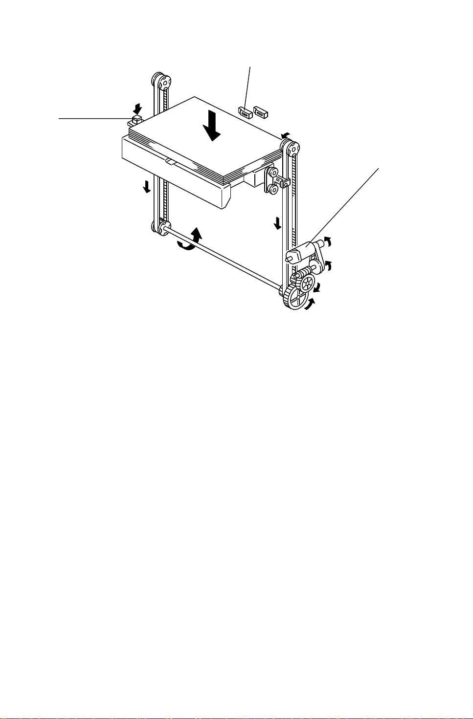
The bottom plate [A] of the LCT is raised and lowered by th e LCT mot or [B]
and the drive belts [C]. When the main swit ch is on and th e LCT cover is
closed, the pick-up sole no id [D] activates and the LCT motor [B] rotates
clockwise to raise the bottom plate until the top sheet pu she s up th e pick-up
roller [E]. When the lift sen sor [F] is de-act ua te d, the copie r CP U de-a ctivates
the LCT motor [B] and the pick-up solenoid [D].
[D]
[F]
[E]
Large
Capacity Tray
5
Page 7
PAPER LIFT MECHANISM 23 April 1993
[C]
[A]
[B]
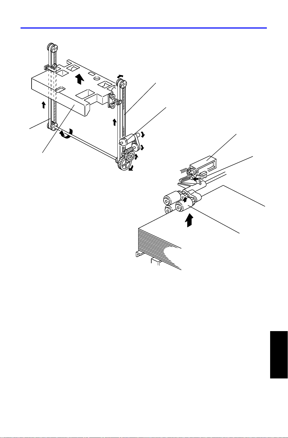
If the tray down switch [A] is presse d, or paper runs out, or a paper jam
occurs in the LCT, the LCT motor [B] rotates counterclockwise to lower the
bottom plate. Howeve r, it is not lowere d all the way down at this time. When
the paper position sensor [C] activa te s, th e LCT mot or sto ps on ce. At this
point, the bottom plate (or the top sheet of paper) is positioned about 5cm
below the top. This gives eno ugh space for the customer to replenish about
500 sheets of paper.
If the tray down switch is the n pre ssed again, the bottom plat e move s down
and stops once again when the top sheet of paper just passes the paper
position sensor. In this way, the botto m plate is lowered 5cm at each press of
the tray down switch. This allows the custo mer to replenish paper in
convenient amounts and at the same position.
6
Page 8

23 April 1993 PAPER END DETECTION
6. PAPER END DETECTION
[B]
The paper end sensor [A] detects paper on the bottom plate. If there is paper
on the table, reflected light from th e pape r activa te s the paper en d sen sor.
When the paper runs out, the paper end senso r de-activates and informs the
copier CPU of the paper e nd cond itio n.
The paper near end senso r [B] also detects the paper and the tray bo tt om
plate. If there is enou gh pap er on the tab le, reflected light from the pap er
activates the paper near en d sensor.
If less than about 60 sheet s of pa pe r remain, the paper near end sensor
de-activates beca use the black colo red bottom plate does not ref lect the light
from the sensor LED.
[A]
[A]
Large
Capacity Tray
7
Page 9

INSTALLATION PROCEDURE 23 April 1993
7. INSTALLATION PROCEDURE
7.1 ACCESSORY CHECK
Check the accessories in the box acco rdin g to the following list:
Description Q’ty
1. Installation procedure......................................................................1
2. New Equipment Condition Report (for –17, –27 machines only)....1
3. LCT feed unit...................................................................................1
4. Small cover - left cover.................... .. .. .. .. .. ......................................1
5. Philips pan head screw - M4 x 6 ............... ............ ............ ............ ..1
6. Philips pan head screw - M4 x 16 ............................... .. .. .. .. .... .. .. .. ..1
7. Tapping screw - M4 x 8........... .. .......... .. .......... .. .................... .. ........1
8. Envelope - NECR (for –17 mach ine only)......... .. .. .. ........................1
8
Page 10

23 April 1993 INSTALLATION PROCEDURE
7.2 INSTALLATION PROCEDURE
[A]
[E]
[A]
[A]
[B]
[B]
[C]
[D]
[F]
CAUTION: Unplug the copier power cord before starti ng the follow ing
procedure.
1. Remove the four strips of tape [A].
2. Open the LCT cover [B] and remove the tape [C] fixing the paper trailing
edge stopper.
3. Remove the tray cushion [D] secu red wit h two strips of tape [E].
4. Remove the LCT connector [F] (3 screws).
Large
Capacity Tray
9
Page 11

[B]
INSTALLATION PROCEDURE 23 April 1993
[A]
[D]
[E]
[C]
[C]
[G]
[F]
5. Open the by-pass ta ble [A] approximately 45 degre es an d pu sh th e
stoppers [B] of the feed unit cover [C] by using a small flat head screw
driver [D], then remove the feed un it cove r.
6. Remove the harness cover [E].
7. Install the LCT feed unit [F] to the copie r (3 scre ws - M 4 x 6).
CAUTION: Do not pinch the harness [G] located below the by-pa ss
table.
10
Page 12

23 April 1993 INSTALLATION PROCEDURE
[D]
[D]
[C]
[B]
[A]
[F]
8. Install the LCT connecto r [A] to the cop ier.
1) Remove the three caps [B].
2) Set the two pins [C] of the LCT connector into the two holes [D] on the
LCT feed unit.
[G]
[E]
3) Install the LCT connector to the copier (3 screws - M4 x 16).
9. Remove the screw fixing the upp er cove r h ing e [E] then slide and remove
the LCT cover [F].
10. Remove the rear upper cover [G] (2 screws).
11
Large
Capacity Tray
Page 13

INSTALLATION PROCEDURE 23 April 1993
[A]
[C]
[B]
[D]
11. Hold the upper stay [A ] of the LCT and place the LCT on the pla te s [B] of
the LCT connector.
CAUTION: Properly place the LCT on the plate [B] of the LCT
connector.
12. Insert the two pins [C] on th e LCT connector into the two holes on the
LCT.
13. Secure the LCT to the LCT connector (3 screws - M 4 x 8).
14. Set the cap [D] in the front screw access hole.
12
Page 14

23 April 1993 INSTALLATION PROCEDURE
15. Connect the connectors.
1) Between the copier and the LCT (3 conne cto rs).
• 13P white
• 13P red
• 16P white
2) Between the LCT and the LCT feed unit (2 conn ect ors).
• 10P white
• 8P white
16. Secure the protective earth wire [A] on the copier.
[A]
Large
Capacity Tray
13
Page 15

INSTALLATION PROCEDURE 23 April 1993
[B]
[A]
17. Install the rear upper cover [A] (2 screws).
18. Install the LCT cover [B] (1 screw).
19. Plug in the copier and check machine operation.
NOTE: The copier automa tica lly re cog nize s tha t th e LCT ha s been
installed.
14
Page 16

23 April 1993 INSTALLATION PROCEDURE
7.3 PAPER SIZE CHANGE
[A]
[A]
[C]
[B]
[D]
[D]
Change the paper size, if the customer requests it.
NOTE: A4/Letter sideways is the factory setting.
1. While covering two sensors [A] with your hand, press the tray down key
[B] to lower the bottom tray.
2. Remove the screws [C] fixing th e front and the rear side fences [D].
3. Tilt the side fence s to th e right (front view) and lift to remove.
4. Position the side fence s accord ing to th e paper size .
5. Fix the side plates (1 screw each).
Large
Capacity Tray
15
Page 17

INSTALLATION PROCEDURE 23 April 1993
[C]
[A]
[B]
B5
A4
LT
[B]
6. Remove the clip [A] and pull ou t th e shaft [B]. Position the pa pe r t railin g
edge stopper [C] according to the paper size.
7. Re-install the shaft [B] and the clip [A].
8. Enter SP mode as follows:
1) Press the clear mode key.
2) Enter "107".
3) Touch the clear/sto p key fo r mo re th an 3 seconds.
1
07
9. Touch the "SP Special Features"
key [D].
[D]
C
16
Page 18

[A]
23 April 1993 INSTALLATION PROCEDURE
10. Touch the "Next" key [A] five times
to select the paper size sett ing
mode (page 6), then touch the
appropriate paper size of "LCT" [B].
[B]
11. Touch the "Index" key [C] .
12. Touch the "Quit" key [D] .
[C]
[D]
13. Check the copy quality an d mach ine operation.
17
Large
Capacity Tray
Page 19

REPLACEMENTS AND ADJUSTMENTS 23 April 1993
8. REPLACEMENTS AND ADJUSTMENTS
8.1 PAPER FEED ROLLERS REPLACEMENT
[D]
1. Open the to p cove r [ A] .
[C]
[A]
[B]
2. Remove the pick-up roller [B ] (1 sna p ring ).
3. Remove the feed roller [C] (1 sna p ring).
4. Remove the separation roller [D] (1 snap ring).
NOTE: Do not touch the surface of the rollers with oily h ands.
The paper feed rollers used in the LCT are different from rolle rs
used in the 1st ~ 3rd feed units in th e pa pe r t ray un it.
18
Page 20

[A]
23 April 1993 REPLACEMENTS AND ADJUSTMENTS
8.2 LCT FEED CLUTCH REMOVAL
[F]
[C]
[B]
[E]
[D]
[B]
1. Remove the rear upper cover [A ] (2 screws).
2. Disconnect the two connectors [B].
3. Remove the harness bra cket [C] (2 screws).
4. Remove the bracket [D] with th e LCT feed motor (3 screws).
5. Replace the LCT feed clutch [E] (2 Allen screws).
NOTE: When installing the LCT feed clutch , set the stopper pin on the
clutch in the cut-out [F] on th e bra cket.
Large
Capacity Tray
19
Page 21

REPLACEMENTS AND ADJUSTMENTS 23 April 1993
8.3 UPPER COVER SWITCHES
[A]
[B]
[C]
❶
1. Remove the right cover [A].
❷
❹
❸
2. Remove the front cover [B].
3. Remove the upper cover switches [C].
NOTE: When installing the switches, set the con necto rs co rrect ly.
❶ Yellow
❷ Blue
❺
❸ Green
❹ Small white
❺ Large white
20
Page 22

23 April 1993 REPLACEMENTS AND ADJUSTMENTS
8.4 SIDE-TO-SIDE REGISTRATIO N ADJUSTMENT
- Rough Adjustment -
1. Loosen the two screws [A] fixing th e sta y [B] .
[B]
[A]
2. Move the stay posit ion to change the side-to-side paper position.
- Fine Adjustment -
1. Enter SP mode (refe r to th e service prog ram access procedure) and
access the side to side adjustment mode ( SP Adjustment - PAGE 4).
1
2. Adjust side to side re gist ration by changing the SP mode dat a.
NOTE: Copies can be made in SP mode . Tou ch the "Copy in SP" key to
select the paper feed sta tio n.
Adjustment standard: less than ±2 mm difference between the original and
the copy.
Large
Capacity Tray
21
 Loading...