

Page 1

20 December 1991 SPECIFICATIONS
1. SPECIFICATIONS
Copy Paper Size B4 (lengthwise)
A4 (lengthwise or sideways)
B5 (lengthwise or sideways)
81/2" x 14" (lengthwise)
81/2" x 11" (lengthwise or sideways)
Copy Paper Weight: 52 g to 93 g (14 lb to 24 lb)
Tray capacity: 1,000 sheets (may vary slightly depending on
paper weight)
Lift Time: Maximum: 12 seconds (50 Hz)
10 seconds (60 Hz)
Power Source: 220 V/60 Hz 0.15 A
220 V/50 Hz 0.15 A
240 V/50 Hz 0.15 A
115 V/60 Hz 0.3 A
110 V/60 Hz 0.3 A
Power Consumption: Maximum 30 W
Dimensions:(W x D x H) 385 mm x 545 mm x 220 mm
(16.2" x 21.5" x 8.7")
Weight: 11.5 kg (25.3 lb)
1
Page 2
MECHANICAL COMPONENT LAYOUT 20 December 1991
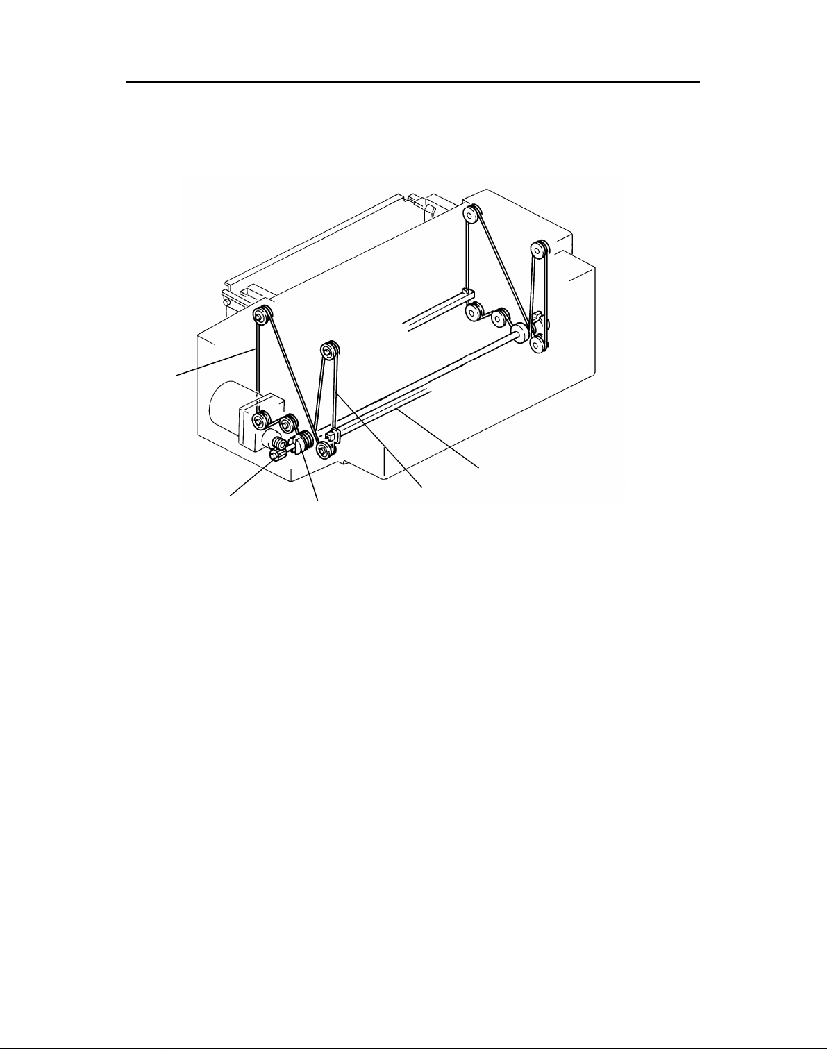
2. MECHANICAL COMPONENT LAYOUT
1
2
1. Drive Wire
2. Drive Gears
3. Drive Pulley
5
4
3
4. Tray Wire
5. Lift Rods
2
Page 3
20 December 1991 ELECTRICAL COMPONENT LAYOUT
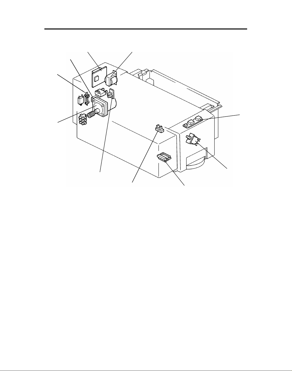
3. ELECTRICAL COMPONENT LAYOUT
2
3
4
5
6
1
7
10
9
8
1. LCT transformer (TR2)
2. LCT PCB (PCB7)
3. Noise Filter
4. Ac fuse (220 V)
4. Circuit breaker (115 V) (NF2)
5. LCT Motor (M15)
6. Surge Suppressor (SS1)
7. Tray down sensor (S34)
8. Paper size sensor (S35)
9. LCT safety switch (SW11)
10. LCT operation panel (PCB1 2)
3
Page 4

ELECTRICAL COMPONENT DESCRIPTIONS 20 December 1991
4. ELECTRICAL COMPONENT DESCRIPTIONS
Index
No.
Motor
5 LCT Motor Lifts and lowers the LCT bottom plate to
Switches
9 LCT safety Switch Disables LCT motor when covers are
Sensors
7 Tray Down Sensor Detects when tray is completely down
8 Paper Size Sensor Determines what size paper is loaded
Printed Circuit Boards
2 LCT PCB Controls LCT tray lift interfaces LCT
10 LCT Operation
Panel
Name Function Symbol
bring paper to feed position and allow
loading of paper.
open. Detects when covers are opened.
to stop tray motor.
into the LCT.
with copier.
Contains the Down SW, Down
indicator, and Open Cover indicator for
the LCT.
P to P
Location
M15 A-10
SW11 A-10
S34 B-10
S35 B-7
PCB7 A-7 to 10
Transformer
1 LCT Transformer Steps down wall voltage to 100 Vac for
LCT.
Circuit Breaker
4 LCT Circuit Breaker Overload protection for LCT. CB2 A-11
Noise Filter
3 Noise Filter Removes electrical noise From the AC
input lines.
6 Surge Suppressor Removes surge current from the AC
input lines.
TR2 A-11
NF2
SS1
4
Page 5
20 December 1991 MECHANICAL OPERATION
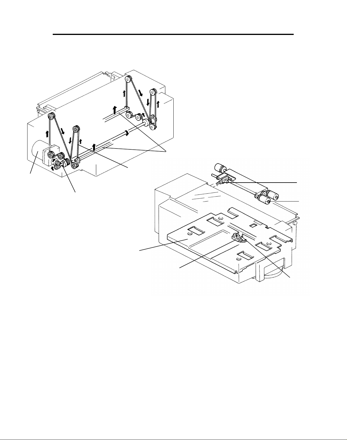
5. MECHANICAL OPERATION
5.1 DRIVE MECHANISM
[E]
[D]
[A]
[G]
[C]
[F]
[B]
[I]
[H]
A reversible ac motor [A] drives the LCT’s bot to m plat e [B ] up and down .
The motor’s drive is transmitted directly to the tray drive shaf t [C] via a worm
gear and worm wheel. The tray wires [D] have brace s on th em, these braces
hold the ends of the two lift rods which support the tray bot to m plat e. When
the wire drive pulley turns clockwise, the bra ces on the wires raise the lift
rods [E] and the tray bottom plat e. The bottom plate rises until the paper in
the tray pushes up the pick-up roller [F], actu at ing the copie r lif t sen sor [G ].
The tray bottom plate lowers when the tray drive motor t urn s the wire drive
pulley counterclockwise. It stops moving down when the actuator plate [H].,
on the left lift rod, actuates the tra y down sensor [I].
5
Page 6
[D]
[E]
MECHANICAL OPERATION 20 December 1991
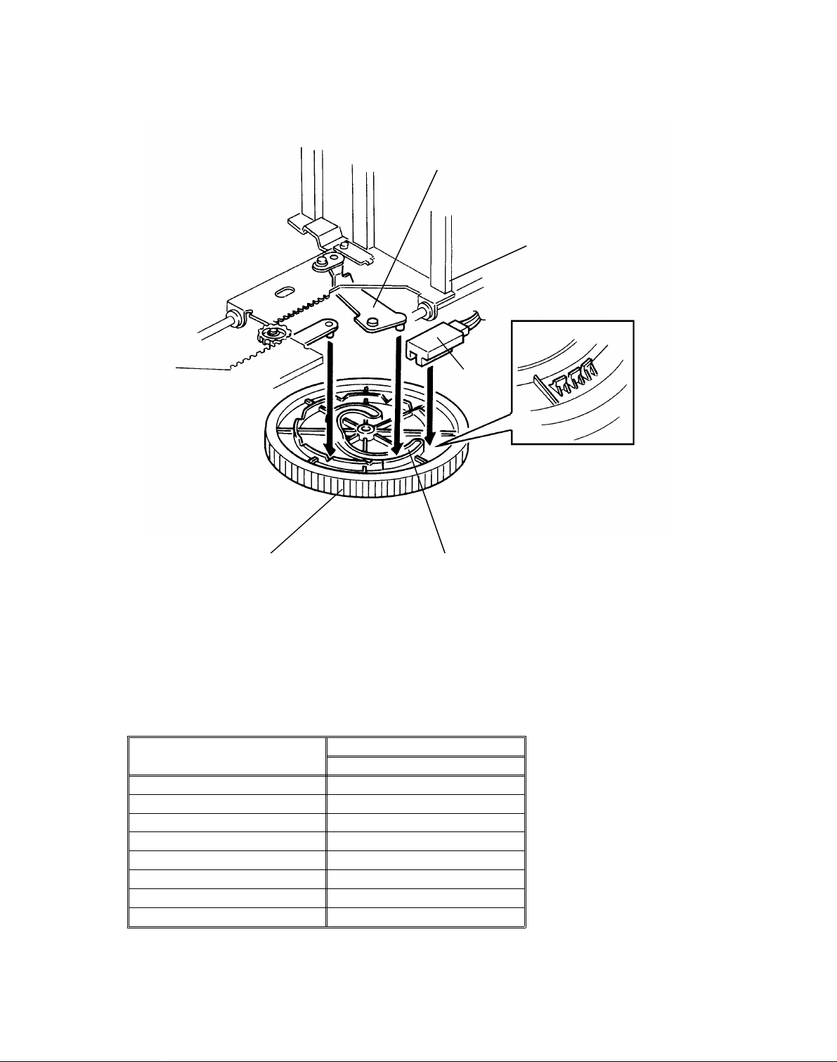
5.2 PAPER SIZE DETECTION
[C]
[F]
[A]
[B]
The paper size dial controls side post positioning and paper size detection.
When the paper size dial [A] is rotated , th e cam gro ove [B] moves the size
lever [C], which repositions th e guide post s [D]. When the dial reaches a
standard paper size, one of the actuat or plates [E] enters the paper size
sensor [F].
Paper Size Detection Tab le (LCT)
Paper Size
B4 00011
A4 Sideways 0 0 1 0 0
A4 Lengthwise 0 0 1 0 1
B5 Sideways 0 0 1 1 0
B5 Lengthwise 0 0 1 1 1
11" x 8
8
8
1/2" 10001
1/2" x 11" 1 0 1 1 0
1/2" x 14" 1 0 1 0 0
12345
Sensor
6
Page 7
20 December 1991 MECHANICAL OPERATION
5.3 COVER SAFETY SWITCH
The cover safety switch monitors whether or not the to p an d side covers are
closed. If either cove r is open , th e safety switch is de-actuat ed .
Pins on the top and bottom actuator levers hold the safety switch actuator.
The top actuator le ver is pushed down by the top cover, while the bottom
actuator lever is pushed in by the side cover. Therefo re, the safety switch
actuates only when bot h th e to p an d side covers are closed.
7
Page 8

[ 24 ]
[ 24 ]
[ 5]
[ 5]
[ 5]
[ 5]
+
+
LCT
Motor
Connection
Detection
–++
ELECTRICAL OPERATION 20 December 1991
6. ELECTRICAL OPERATION
100 V
Tray Down
Copier
Main PCB
104-A1
24 V
922-1
922-2
–
SSR 1
AC
Cover
Switch
100 V
AC
(H)
Tray Up
Down Key
Door Open
Tray Down
Sensor
104-B1
103-B13
103-A14
104-B13
104-A14
922-3
–
SSR 2
LCT PCB
–
Cover
Switch
Tray
Down
Sensor
5 V
6.1 DOWN OPERATION
The bottom plate moves do wn only wh en the Down key is presse d or pa pe r
end occurs. When the Down key is pressed, the copie r Ma in PCB send s a
"Tray Down" signal to turn on SSR1 energ izing the drive mot or to move the
tray down. The down sensor is actuat ed when the botto m plate is fully
lowered, the copie r main PCB then stops sending th e "Tra y Do wn" sig nal
which causes the drive moto r t o tu rn off. The Cover safety switch preve nts
operation of the drive mo to r. When the cover is opened, the 10 0 volt ac line is
cut. When the cover is closed again, the bottom plate moves up.
GND
6.2 UP OPERATION
Opening and closing th e up pe r or side LCT cover while the bottom plate is in
the down position starts the up operation. When the cover is opened and
closed, the copier Main PCB sen ds a "Tray Up" signal to turn on SSR2
energizing the drive moto r to move the tray up. The drive mot or stays on until
the paper pushes up the pick-up roller, act ua tin g th e copier lift sensor. This
causes the copier main PCB to sto p sending the "Tray Up" sign al which turns
off drive motor. The cover safe ty switch preve nts operation of the drive motor.
When the cover is opened, the 100 volt ac line is cut. Whe n the cover is
closed again, the bottom plate moves up.
8
Page 9

20 December 1991 INSTALLATION PROCEDURE
7. INSTALLATION PROCEDURE
ACCESSORY CHECK
Check the quantity and cond itio n of the accessories in the box accord ing to
the following list:
1. Installation Procedure.................. .......... .......... .......... .. .......... .......... ..1
2. New Equipment Condition Report............. .............. .. .. .. .............. .. .. ..1
(17 and 27 machines)
3. Intermediat e Harness.............. .......... .. .......... .......... .......... .......... ......1
4. Mounting Stud ...................................................................................2
5. Screw................. .......... .......... .......... .......... .......... .. .......... .......... ........1
6. Harness Clamp.......... .......... .......... .......... .......... .. .......... .......... ..........2
9
Page 10

INSTALLATION PROCEDURE 20 December 1991
[A]
[A]
[E]
[D]
[B]
[C]
INSTALLATION PROCEDURE (on 2nd Paper Feed Station)
CAUTION: Make sure that the wall-outlet is near the LCT and easily
accessible.
NOTE: When the 3rd paper feed unit is installed, install the LCT on th e
3rd paper feed station.
1. Turn off the main switch and unplu g the cop ier.
2. Remove the strips of shipping tape [A].
3. Remove the copier left lif t hand le [B ] (2 screws).
4. Remove the 2nd casset te arm [C] (2 screws) and the cap [D] of the left
cover.
5. Open the rear cover [E] (2 screws).
10
Page 11

20 December 1991 INSTALLATION PROCEDURE
[C]
[E]
[D]
[B]
[A]
[E]
CAUTION: When closing the power supply section [A], use the
(#9) grounding screw [B] for proper grounding.
6. Disconnect the 12P intermediate harness [C].
7. While passing the harn ess through the access hole, set the LCT to the
2nd paper feed station.
8. Fix the LCT using two moun ting studs.
9. Open the power supply sect ion (1 scre w).
10. Connect the harness as follows:
1) 12P black connector (LCT) - 12P black conn ect or (cop ier)
2) 8P black connector (LCT) - 8p black connect or (cop ier)
NOTE: Set the harness [D] to harness clamp [E] so that it would not
touch the drive section.
11. Close the power supply section and copier’s rear cover.
11
Page 12

[C]
INSTALLATION PROCEDURE 20 December 1991
[A]
[B]
[D]
12. Perform the followin g if necessary:
1) 220 to 230 (240) Volts conversion (European version only)
1. Remove the rear cover [A] (4 screws).
2. Disconnect the 220 Volt connector [B], and con ne ct th e 23 0 (240)
Volt connector [C].
3. Erase both "220 V" inscriptions written on the decal of the rear
cover, and write "230 V (240 V) on the decal as sho wn.
2) Stick the accessory caution de cal on the copie r re ar cove r as sh own .
(U.S. version only)
13. Plug in the copier and LCT, and check the LCT operation.
12
Page 13

20 December 1991 INSTALLATION PROCEDURE
[B]
[A]
[C]
[D]
[E]
INSTALLATION PROCEDURE (on 3rd Paper Fee d Stati on)
14. Perform steps 1 and 2.
15. Remove the 3rd cassett e arm [A] (2 screws) and the cap [B] of th e lef t
cover.
16. Remove the copier rear cover [ C] (4 screws).
17. Remove the rear cover [D] of the paper feed unit (2 screw).
18. Remove the harness bracket [E].
13
Page 14

INSTALLATION PROCEDURE 20 December 1991
[B]
[A]
[C]
19. While passing the harn ess th rough the access hole, set the LCT to the
3rd paper feed station.
20. Fix the LCT using two mounting studs.
21. Open the power supply section [A] (1 screw).
22. Disconnect the 12P brown connector [B] of the 3rd paper feed unit, and
connect the accessory harn ess [C] to the 12P brown conne cto r, as shown.
14
Page 15

20 December 1991 INSTALLATION PROCEDURE
[D] [C]
[A]
[B]
[F]
[E]
23. Connect the 8P black connector [A] to the 8P black connector [B] of the
LCT.
24. Connect the 12P black con ne ctor [C] of the LCT to the 12P bla ck
connector [D] of the copier, and set the two harn ess clamp s [ E] .
25. Set the harness [F] to th e ha rness clamp as shown so that it would not
touch the drive section.
15
Page 16

INSTALLATION PROCEDURE 20 December 1991
[B]
[A]
CAUTION: When closing the power supply section [B], use the
(#21) grounding screw for proper grounding.
26. Install the harness bracket [A] (1 screw), as shown.
27. Close the power supply section and reinstall all the covers.
28. Plug in the copier and LCT, and check the LCT operation.
29. Perform step 12 and 13.
16
Page 17

[C]
20 December 1991 REPLACEMENT AND ADJUSTMENT
8. REPLACEMENT AND ADJUSTMENT
8.1 TRAY WIRE REPLACEMENT
[D]
[A]
[F]
[B]
CAUTION: Unplug the tray power supply cord.
Rear wire
1. Remove LCT from the copier.
2. Remove the following parts:
a) Rear cover (4 screws)
b) Transformer assembly with LCT PCB [A] (1 screw, 6 connectors)
c) AC power terminal [B] (1 screw)
d) Drive motor assembly [C] (2 screws)
e) Surge suppresser assembly [D] (2 screws)
Front side
1. Remove the following parts:
a) Front cover (loosen 3 screws)
[E]
b) Safety switch actuator [E] (2 E-rings)
c) Safety switch assembly [F] (2 screws)
17
Page 18

[E]
[D]
REPLACEMENT AND ADJUSTMENT 20 December 1991
WP1
[F]
WP3
WP4
[A]
WP2
[C]
[B]
- Common Procedure for Front and Rear Wires NOTE: The wrapping directions for the front and rear wires are opposit e.
1. Loosen the wire tightener [A] (1 screw).
2. Insert the bead [B] (u nma rked) into the rear slot of the drive pulley.
3. Loop the wire around the drive pulley [C], as shown (one and a half turns).
4. Run the wire over WP1, WP2, WP3, and WP4 in tu rn while also pla cing
the lift rod’s ends in the braces [D].
5. Insert the bead [E] (red) into the other slot of the drive pulley.
6. Loop the wire around the drive pulley, as shown (two and a half turn s).
7. Hook the wire on the tightener pulley [F].
8. Move the rods up and do wn manually to ensure that the drive wire doe s
not overlap on the pulley.
9. Tighten the wire using the tightener (1 screw).
10. Reassemble.
18
Page 19

20 December 1991 REPLACEMENT AND ADJUSTMENT
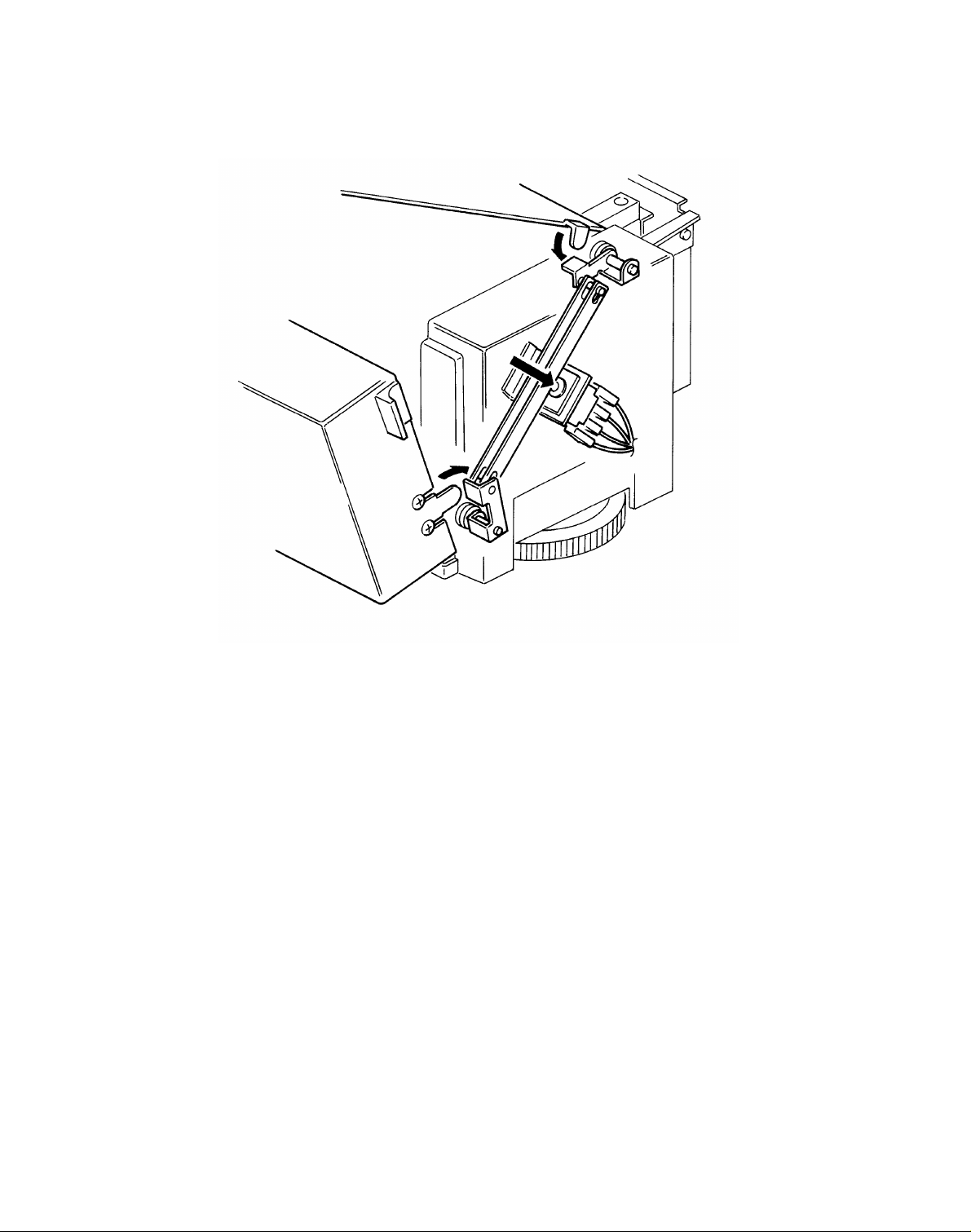
8.2 TRAY DOWN SENSOR REPLACEMENT
[A]
[A]
[B]
[C]
1. Open the side cover (1 screw).
2. Remove the top, front and rear covers (5 screws).
3. Remove the two post tops [A ] (3 screws ea ch).
4. Remove the tray bottom plate [B] (4 screws) taking care not to damage
the 6 guide posts [C].
19
Page 20

[F]
REPLACEMENT AND ADJUSTMENT 20 December 1991
[A]
[B]
[C]
[E]
[D]
5. Move the tray drive motor assembly [A] (2 screws) to the rear to
disengage the tray drive shaft [B] from the wire drive pulley [C].
6. Raise the lift rods [A].
7. Remove the front inner cover [E] (1 short and 1 long screw).
8. Replace the tray down sensor [F] (1 screw and connector).
20
Page 21

[B]
20 December 1991 REPLACEMENT AND ADJUSTMENT
8.3 PAPER SIZE SENSOR REP LACEMENT
[A]
1. Perform steps "1" to "7" of th e Tray Down Sen sor Rep lacement
procedure.
2. Remove the paper size sensor bra cket [A] (1 screw).
3. Replace the paper size sensor [B] (1 screw and 1 connector).
21
Page 22

REPLACEMENT AND ADJUSTMENT 20 December 1991
8.4 SIDE REGISTRATION ADJUSTME NT
[C]
(B)
(B)
(B)
[A]
After installing the large capacity tray, confirm the side registration of the
large capacity tray. The side-t o-side registration of A4 side ways (LT
sideways) copies should be the same as that of the first cassette.
If the side registration is inco rrect , ad just it as follo ws:
1. Remove LCT from the copier.
2. Remove the screw [A].
3. Loosen six screws [B].
4. Adjust the righ t fra me [C] position according to th e amount of the side
registration gap to correct.
5. Tighten and install all screws.
6. Install LCT.
7. Confirm that the side registration is adjusted correctly.
22
 Loading...