

Page 1

1. SPECIFICATIONS
28 February 1989
Copy Paper Size:
Copy Paper Weight:
Tray Capacity:
Lift Time:
Power Source:
Power Consumption:
Dimensions:
(W x D x H)
Weight:
B4 (lengthwise)
A4 (lengthwise or sideways)
B5 (lengthwise or sideways)
8½” x 14” (lengthwise)
8½” x 11” (lengthwise or sideways)
52 g to 93 g (14 Ib to 24 lb)
1,000 sheets (may vary slightly depending
on paper weight)
Maximum:
220 V/60 Hz
220 V/50 Hz 0.15 A
240 V/50 Hz 0.15 A
115 V/60 Hz
110 V/60 Hz
Maximum 30 W
410 mm x 545 mm x 220 mm
16.2” x 21.5” x 8.7”
12 kg (26.4 lb)
12 seconds (50 Hz)
10 seconds (60 Hz)
0.15 A
0.3 A
0.3 A
11-1
Page 2

28 February 1989
2. MECHANICAL COMPONENT LAYOUT
1. Drive Wire
2. Drive Gears
3. Drive Pulley
4. Tray Wire
5. Lift Rods
11-2
Page 3
28 February 1989
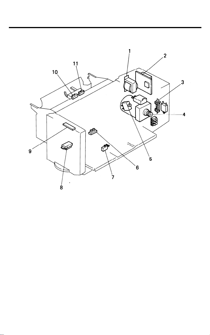
3. ELECTRICAL COMPONENT LAYOUT (FT4460)
1. LCT transformer (TR2)
2. LCT PCB (PCB7)
3. Ac fuse (220 V)
3. Circuit breaker (115V) (NF2)
4. LCT motor (M15)
5. LCT safety switch (SW11)
6. Tray down sensor (S34)
7. Positioning switch (SW12)
8. Paper size sensor (S35)
9. LCT operation panel (PCB12)
10. Paper end sensor (S36)
11. Upper limit sensor (S37)
11-3
Page 4
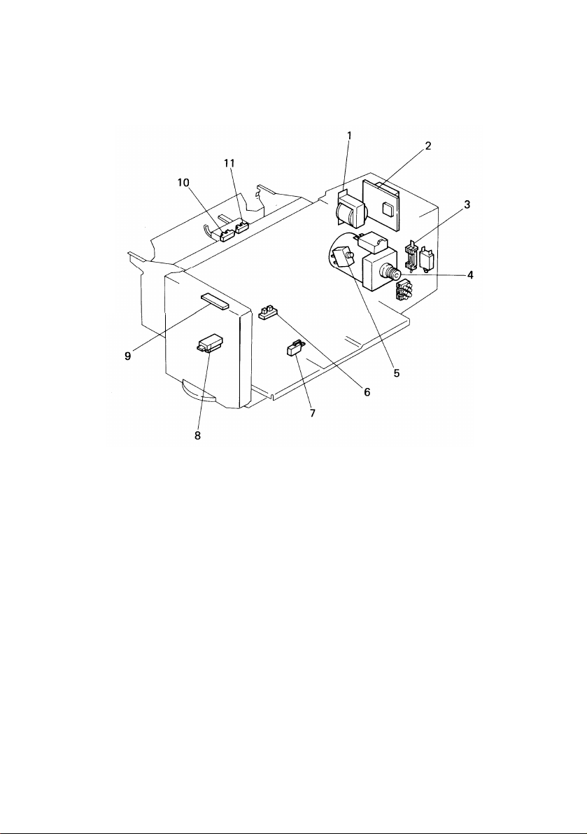
ELECTRICAL COMPONENT LAYOUT
1.
LCT transformer (T-2)
LCT PCB (PCB-12)
2.
Ac fuse (F-2) (220 V)
3.
Circuit breaker (CB-2) (115 V)
3.
LCT motor (M-17)
4.
LCT safety switch (SW-11)
5.
31 January ’89
Tray down sensor (S-39)
6.
7.
Positioning switch (SW-1 2)
Paper size sensor (S-40)
8.
9.
LCT operation panel (PCB-13)
10.
Paper end sensor (S-41 )
11.
Upper limit sensor (S-42)
9-3
Page 5

28 February 1989
4. ELECTRICAL COMPONENT DESCRIPTIONS
Index
No.
Motor
4
Switches
5
7
Sensors
6
8
10
11
Printed Circuit Boards
2
Name
LCT Motor
LCT Safety Switch
Positioning Switch
Tray Down Sensor
Paper Size Sensor
Paper End Sensor
Upper Limit Sensor
LCT PCB
Function
Lifts and lowers the LCT bottom plate to
bring paper to feed position and allow
loading of paper.
Disables LCT motor when covers are
open. Detects when covers are opened.
Detects when paper size dial is in a standard paper size position.
Detects when tray is completely down to
stop tray motor.
Determines what size paper is loaded into
the LCT.
Detects paper end condition for LCT.
Detects the correct feed height of the
stack of paper in the LCT.
Controls LCT tray Iift interfaces LCT with
copier.
Symbol
M15 A-10
SW11
SW12 B-7
S34
S35 B-7
S36 B-9
S37 B-9
PCB7 A-7 to 10
P to P
Location
A-10
B-10
LCT Operation
9
Panel
Transformer
1
LCT Transformer
Circuit Breaker
LCT Circuit Breaker
3
Contains the Down SW, Down indicator,
and Open Cover indicator for the LCT.
Steps down wall voltage to 100 Vac for
LCT.
Overload protection for LCT.
11-4
PCB12 B-9
TR2
NF2
A-11
A-11
Page 6

5. MECHANICAL OPERATION
28 February 1989
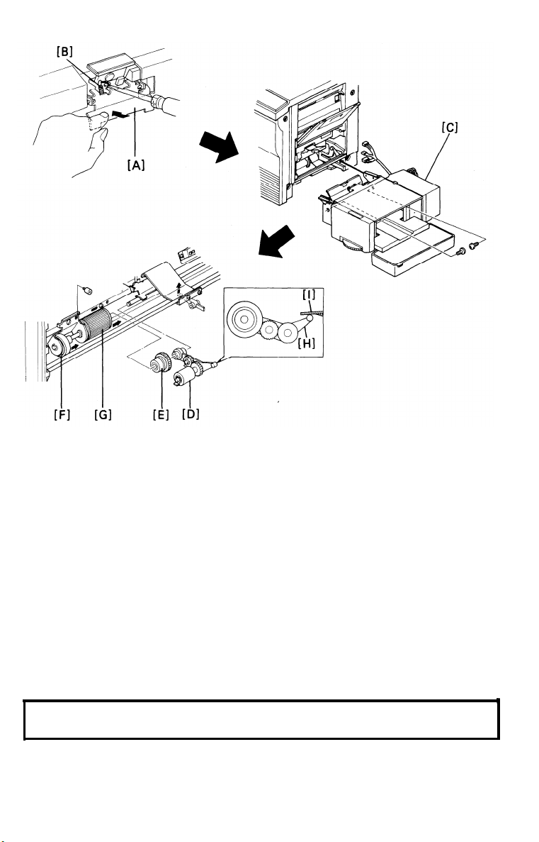
5.1 DRIVE MECHANISM
A reversible ac motor [A] drives the LCT’s bottom plate up and down.
The motor’s drive is transmitted directly to the tray drive shaft [B] via a worm
gear and worm wheel. The tray wires [C] have braces on them; these braces
hold the ends of the two lift rods which support the tray bottom plate. The
braces on the wires raise the lift rods [D] and the tray bottom plate when the
pulley turns counterclockwise, and they lower them when the pulley turns
clockwise.
11-5
Page 7

28 February 1989
5.2 PICK-UP ROLLER MECHANISM
The pick-up roller [A] is driven by a drive gear [B] to initialize paper feed from
the LCT.
The paper end sensor [C] and the upper limit sensor [D] are incorporated in
the LCT not the copier. The paper end sensor is used to detect paper end
and the upper limit sensor detects when the tray has reached its upper limit
when the tray is being raised.
11-6
Page 8
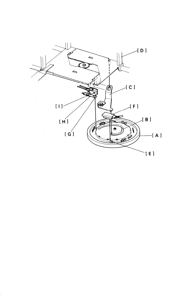
5.3 PAPER SIZE DETECTION
28 February 1989
The paper size dial controls side post positioning and paper size detection.
When the paper size dial [A] is rotated, the cam groove [B] moves the size
lever [C], which repositions the guide posts [D]. When the dial reaches a
standard paper size, one of the actuator plates [E] enters the paper size sensor [F]. At the same time, the pin [G] on the leaf spring [H] drops into a notch
on the inside rim of the dial and the positioning switch [I] deactuates.
When the positioning switch opens, the scan signal is applied to the LCT
paper size sensor. The paper size sensor then reads the pattern of the ac-
tuator plate and sends paper size data to the copier’s CPU.
When the paper size dial is positioned at a non-standard paper size, the
positioning switch is actuated (closed). In this case, the LCT cannot be used;
the Load Paper indicator lights and no paper size is displayed on the operation panel. This prevents the skewing that would occur if the guide posts were
not at the correct position.
11-7
Page 9
28 February 1989
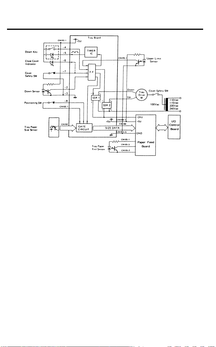
6. ELECTRICAL OPERATION
6.1 DOWN OPERATION
The bottom plate moves down only when the Down key is pressed or paper
end occurs. When the Down key is pressed, the flip-flop changes state (all
outputs change from LOW to HIGH or vice versa). Then, three things happen
simultaneously: (1) The gate circuit turns off, preventing size data from being
sent to the copier; (2) The timer circuit turns on, causing the LED in the down
key to blink; and (3) SSR1 turns on, energizing the drive motor to move the
tray down.
The down sensor is actuated when the bottom plate is fully lowered. This
causes the flip-flop to change back to its original state, which turns off SSR1
and resets the timer circuit. The LED in the Down key stays continuously on.
6.2 UP OPERATION
Opening and closing the upper or side LCT cover while the bottom plate is in
the down position starts the up operation. This causes the gate circuit to send
paper size data to the copier. At the same time the cover safety switch changes the state of the flip-flop and the flip-flop energizes SSR2, which turns on
the drive motor to move the tray up. The drive motor stays on until the paper
pushes up the pick-up roller. The actuator on the pick-up roller bracket then
moves out of the upper limit sensor; this again changes the flip-flop’s state
and the motor stops.
The cover safety switch prevents operation if the cover is open by cutting off
the ac 100 volt line.
11-8
Page 10

28 February 1989
7. ACCESSORY CHECK
Check the quantity and condition of the accessories in the box according to
the following list:
1. Installation Procedure
(115V - English only / 220V - Five Languages)
2. New Equipment Condition Report . . . . . . . . . . . . . . . . . . . . . . . . 1
3. Envelope for NECR (115V only)
4. Pick-up Roller Assembly
5. Gear
6. Screw (M4 x 6)
7. Screw (M4 x 8)
8. Grounding screw (M4 x 10)
9. LCT Mounting Bracket
10. Harness Clamp
11. Caution Decal
. . . . . . . . . . . . . . . . . . . . . . . . . . . . . . . . . . . . . . . . . . . . . . . . . . . . . . . . . . . . . . . . . . . . .
“A” type bracket: For 3rd paper feed station . . . . . . . . (2)
of FT4460
“B” type bracket: (For other model) . . . . . . . . . . . . . . . . . . . . . (2)
“C” type bracket: (For other model) . . . . . . . . . . . . . . . . . . . . . (2)
. . . . . . . . . . . . . . . . . . . . . . . . . . . . . . . . . . . . . . . . . . . . . . . . . . . . . . .
(115V - English and French,
220V/240V - English and German)
. . . . . . . . . . . . . . . . . . . . . . . . . . . . . . . . . . . . . . . . . . .
. . . . . . . . . . . . . . . . . . . . . . . . . . .
. . . . . . . . . . . . . . . . . . . . . . . . . . . . . . . . . . . . . . .
. . . . . . . . . . . . . . . . . . . . . . . . . . . . . . . . . . . . . . . . . . . . . . . . . . . . .
. . . . . . . . . . . . . . . . . . . . . . . . . . . . . . . . . . . . . . . . . . . . . . . . . . . . .
. . . . . . . . . . . . . . . . . . . . . . . . . . . . . . . . . .
. . . . . . . . . . . . . . . . . . . . . . . . . . . . . . . . . . . . . . . . .
. . . . . . . . . . . . . . . . . . . . . . . . . . . . . . . . . . . . . . . . . . . . . . . . . . . . .
1
1
1
1
4
1
2
6
1
1
12. Multilingual Decals (220V/240V only) . . . . . . . . . . . . . . . . . . . . 5
11-9
Page 11

28 February 1989
8. INSTALLATION PROCEDURE (FT4460)
8.1 LCT INSTALLATION
1. Turn off the copier main switch and unplug the copier power cord.
2. Remove the strips of shipping tape [A].
3. Lift the copier and remove the cover plate [B] on the right side of the system table (2 screws), and then reposition the copier on the table.
NOTE:
If the system does not contain the special system table, move the
copier to the right so that the Large Capacity Tray can overhang the
end of the table as shown.
11-10
Page 12

28 February 1989
4. Mount “A’’ type brackets [A] (2 screws each).
NOTE:
Use “A” type brackets when installing the LCT to the third paper feed
station.
.
5
Remove the copier rear cover [B] (4 screws).
.
6
Open the manual feed table and the front cover, and remove the right
cover [C] (6 screws).
7.
Remove the 3rd cassette arm assembly [D] (4 screws).
.
Move the sub roller unit [E] and the third feed roller [F] to the left (1 stud
8
screw) as shown.
CAUTION:
Be careful not to peel off the mylar [G].
9. Remove the nylon hub [H] and the snap ring [I].
10. Reinstall the right cover.
11-11
Page 13
28 February 1989
11. Press the pad positioning plate [A] down and unhook the spring [B]
using a small screwdriver.
12. Place the large capacity tray [C] in the cassette holder on the third paper
feed station.
NOTE: Make sure that the rib of the tray side plate fits into the groove on
the cassette holder.
13. Open the side and top covers and secure the tray to the third paper feed
station (2 screws).
14. Install the pick-up roller assembly [D] and the gear [E] on the 3rd feed
roller shaft.
15. Now move the sub roller unit [F] and the third feed roller [G] to the right
and reinstall them (1 stud screw) while holding the friction pad down.
CAUTION:
Make sure that the paper position feeler [H] is positioned under
the sensor actuator [I].
11-12
Page 14

21 April 1989
16. Remove the harness hole plate [A] (1 screw) and pass the tray harness
through the harness hole [B].
17. Disconnect CN508 and CN507 on the paper feed PCB [C].
18. Connect the tray harness to the paper feed PCB [C] as follows:
3P red connector [D] to CN508
4P white connector [E] to CN510
7P white connector [F] to CN507
19. For 240 volt areas only:
Remove the rear cover of the LCT (5 screws), disconnect the 220V con-
nector [G] and connect the 240V connector [H] as shown, and then
reinstall the rear cover of the LCT.
11-13
Page 15

21 April 1989
20. Reinstall the rear cover of the copier.
21. Apply the caution decal [A] on the copier rear cover.
22. Plug in the machine and turn on the copier main switch.
23. Select Feed station priority at power on, using SP#20.
Data 0 –> LCT priority
Data 1 –> Cassette from 1st feed station
24. Check the LCT operation and fill out the New Equipment Condition
Report.
11-14
Page 16

28 February 1989
8.2 ADJUSTING SIDE REGISTRATION
After installing the large capacity tray, confirm the side registration of the large
capacity tray. The side-to-side registration of A4 sideways (LT sideways)
copies should be the same as that of the first cassette.
If the side registration is incorrect, adjust it as follows:
1. Load 2 or 3 sheets of paper on the tray [A] and position the paper size
dial [B] to A4 sideways (LT sideways).
NOTE:
2.
Do not move the paper size dial while adjusting the side registration.
Turn on the copier main switch and raise the tray to the paper feed position.
Turn off the copier main switch.
.
3
4.
Remove the front inner cover [C] (2 screws) using a stubby screwdriver.
NOTE: Insert the chain [D] into the middle slot of the front inner cover as
shown and remove the front inner cover while turning it.
5. Mark the current position of the side guide [E] on the plastic top cover
using a pencil or tape.
NOTE: Be careful not scratch the top cover.
11-15
Page 17

28 February 1989
6. Loosen the shaft mounting plate [A] (1 screw).
7. Loosen the shaft bracket [B] (2 screws).
CAUTION:
Don’t remove the 2 screws.
Be careful not to damage the heads of the screws as the
screws are not visible.
8. Slide the front [C] and rear [D] side guide plates at the same time by
making reference to the difference of the side registration on the copies
and the mark on the top cover. (Adjusting range ± 4 mm.)
CAUTION:
Hold the gear 28T [E] so that the gear 28T [E] does not turn.
9. Mount the shaft bracket [B] (2 screws) and make copies to confirm the
registration.
NOTE:
If there is still a side registration gap, readjust the position of the
front [C] and rear [D] side guide plates.
10. Reinstall all parts.
11-16
Page 18

15 MARCH 1987
INSTALLATION PROCEDURE (FT4480)
1.
Turn off the main switch and unplug the power supply cord of the
copier.
2.
Move the copier to the right.
NOTE: As this system does not contain a special system
be moved to the right so that the large capacity
end of the table.
3.
Open the right front door [A].
Pull out the cassette tray [B].
4.
5.
Remove the right inner cover [C] (3 screws with flat washer).
6.
Remove the right front door [A].
7.
Remove the front right side cover [D] (2 screws).
table, the copier must
tray can overhang the
7-2
Page 19

15 MARCH 1987
8.
Remove the rear
Remove the rear
9.
Remove the paper feed PCB [B] (1 screw).
10.
Remove the feed stay [C] (3 screws).
11.
Remove the cassette arm lever [D] (1 spring [E], 1 E-ring [F]).
12.
Remove the cassette arm assembly [G] (front - 1 E-ring [H] and 1
13.
cover (2 screws).
right side cover [A] (2 screws).
bushing [I], rear - 1 bushing [J]).
Press the pad positioning plate [K] down and unhook the spring [L]
14.
using a small screw driver.
Slide off the feed roller [M] (1 snap ring [N]).
15.
Remove the nylon hub [O] from the feed roller.
16.
Remove the E-ring [P] of the feed roller shaft.
17.
7-3
Page 20

15 MARCH 1987
18. Install the mounting bracket [A] (Type
Capacity Tray (2 M4 X 6 screws each).
19. Remove the 5 strips of shipping tape [B].
7-4
C, Chrome) on the Large
Page 21

15 MARCH 1987
20. Reinstall the front right side cover [A] and rear right side cover [B].
21. Place the large capacity tray [C] in the cassette holder on the 2nd
feed station.
NOTE: Make sure that the rib of the tray side plate fits into the groove of the
cassette holder.
22. Open the side and top covers and secure the tray to the 2nd feed
station (2 screws, M4 X 10).
23. Disconnect CN226 and CN227, and fix these connectors with the
harness clamp.
24. Connect the tray harness to the paper feed PCB [D] as follows:
* 3p connector to CN226
* 4p connector to CN231
* 7p connector to CN227
7-5
Page 22

15 MARCH 1987
25. Install the pick-up roller assembly [A] on the feed roller shaft.
26. Install the gear [B] on the feed roller shaft.
27. Reinstall the feed roller [C] (1 snap ring [D]).
28. Make sure that the paper position feeler [F] is positioned as shown.
29. Reinstall all covers.
30. Stick the caution decal [E] on the copier rear cover.
31. Check the operation of the Large Capacity Tray.
32. Fill out the New Equipment Condition Report.
7-6
Page 23

31 March 1987
INSTALLATION PROCEDURE (FT5560)
1-17
Page 24

31 March 1987
2.
Remove the rear expansion unit cover [A]
(2 screws).
3.
Remove the front [B] and rear [C] right
covers of the expansion unit (front: 2
screws, rear: 1 screw).
4.
Remove the right side safety switch assembly [D] (1 screw).
5.
Disconnect the expansion interface harness
from the expansion unit.
6.
Pull out the 3rd paper feed unit [E] from the
expansion unit (4 screws).
7.
Remove the 3rd paper feed PCB
(1 screw).
8.
Refer to the
capacity tray
common procedure
installation.
1-18
assembly
for large
Page 25

1-19
Page 26

Slide off the feed roller [A] (1 snap ring [B]).
6.
Remove the nylon hub [C] from the feed
7.
roller.
8.
Remove the E-ring [D] on the feed roller
shaft.
9.
Press the pad positioning plate [E] down
and unhook the spring [F] using a small
screw driver.
10.
Install the mounting bracket (Type B) [G] on
the large capacity
tray [H] (screws).
Remove the strips
11.
1-20
of shipping tape [I].
Page 27

12. 3rd feed station only:
Reinstall the 3rd paper feed PCB.
13. Disconnect the red 3P connector from:
CN909 (3rd paper feed PCB [A])
or
CN957 (paper bank PCB [B]).
14. 3rd feed station only:
a. Pass the expansion interface harness
and the safety switch assembly around
their respective expansion unit uprights.
b. Reinstall the 3rd paper feed unit into the
expansion
safety switch assembly (1 screw).
c. Reconnect the expansion interface har-
ness to the expansion unit (CN901, 902,
and 903 of the 3rd paper feed PCB).
d. Reinstall front and rear right expansion
unit covers.
unit (4 screws) and the
1-21
Page 28

31 March 1987
15.
Install the pick-up roller assembly [A] on the
feed roller shaft.
16.
Install the plastic gear [B] on the feed roller
shaft.
17.
Reinstall the feed roller [C] (1 snap ring)
and fix the pick-up roller [D] in a raised
position with (shipping) tape [E] as shown.
18.
Place the large capacity tray [F] in the cassette holders of either the 3rd or 5th feed
station. (Make sure that the rib of the tray
side plate fits into the groove of the cassette holder.) Then, remove the strip of
tape holding the pick-up roller.
19.
Secure the large capacity tray to the feed
station (2 long screws).
1-22
Page 29

20.
Disconnect the white 7P connector from:
CN908 (3rd paper feed PCB [A]) or
CN956 (paper bank PCB [B]).
Connect the tray harness to the expansion
21.
unit or the paper bank as follows:
4P connector to:
CN911 (3rd paper feed PCB)
or
CN958 (paper bank PCB)
7P connector to:
CN908 (3rd paper feed PCB)
or
CN956 (paper bank PCB)
3P connector to:
CN909 (3rd paper feed PCB)
or
CN957 (paper bank PCB)
5th Feed Station Only:
22.
Remove the harness hole plate [C] (1 screw).
Fix the tray harness with the nylon clamp
23.
[D].
1-23
Page 30

31 March 1987
24.
Reinstall the covers except for the expansion and copier (type 2 only) rear covers
for duplex installation.
Stick the caution decal [A] on the copier
25.
rear cover.
Fill out New Equipment Condition Report.
26.
1-24
Page 31

Installation Procedure (FT4490)
31 January ’89
1. Turn off the main switch and unplug the power supply cord of the copier.
2. Move the copier to the left and remove the cover plate [A] on the right
side of the system table (1 screw), then reposition the copier on the table.
NOTE: If this system does not have the special system table, move the
copier to the right so that the Large Capacity Tray can hang over the
edge of the table as shown above.
9-9
Page 32

31 January ’89
3. Remove the rear cover (2 screws).
4. Remove the rear right side cover [A] (2 screws).
5. Lower the main PCB plate [B] and remove the paper feed PCB [C] (1
screw).
6. Remove the cassette arm lever spring [D].
7. Remove the cassette arm assembly [E] (1 screw).
8. Press the pad positioning plate [F] down and unhook the spring [G]
using a small screw driver.
9. Slide off the feed roller [H] (1 snap ring [1]).
10. Remove the nylon hub [J] from the feed roller.
11. Remove the E-ring [K] of the feed roller shaft.
12. Reinstall the paper feed PCB and the rear right side cover.
9-10
Page 33

31 January ’89
13. Install the mounting bracket [A] (Type C, Chrome) on the large
capacity
tray (2 screws, M4 x 6 each).
14. Remove the 5 strips of shipping tape [B].
15. Place the large capacity tray in the cassette holder on the 2nd feed sta-
tion.
NOTE: Make sure that the rib of the tray side plate fits into the groove of the
cassette holder.
16.
Open the side and top covers and secure the tray to the 2nd feed station
(2 screws, M4 x 10).
17.
Disconnect CN226 and CN227, and set these connectors to the harness
clamp.
18.
Connect the tray harness to the paper feed PCB [C] as follows:
* 3p connector to CN226
* 4p connector to CN231
* 7p connector to CN227
9-11
Page 34

31 January ’89
[i]
19.
Clamp the LCT harness [A] to the support
bracket [B] of the PCB plate
with the nylon wire clamp [C].
20.
Install the pick-up roller assembly [D] on the
21.
Install the gear [E] on the feed roller shaft.
22.
Reinstall the feed roller [F] (1 snap ring [G]).
23.
Make sure that the paper position feeler [H] is positioned as shown.
24.
Reinstall all covers.
25.
Stick the caution decal [1] on the copier rear cover.
26.
Check the operation of the Large Capacity Tray.
27.
Fill out the New Equipment Condition Report.
feed roller shaft.
9-12
Page 35

16 April ’88
INSTALLATION PROCEDURE (FT4430)
I
1
.
Turn off the main switch and unplug the power supply cord of the copier.
2
.
Move the copier to the right.
I
NOTE: The copier must be moved to the right so that the large capacity tray
can overhang the end of the table.
.
Remove the rear cover (2 screws).
3
4
.
Remove the rear right side cover [A] (2 screws).
.
5
Remove the paper feed PCB [B] (2 studs).
.
Remove the cassette arm lever spring [C].
6
7
,
Remove the cassette arm assembly [D] (1 screw).
.
8
Press the pad positioning plate [E] down and unhook the spring [F] using
a small screw driver.
.
9
Slide off the feed roller [G] (1 snap ring [H]).
10
.
Remove the nylon hub [1] from the feed roller.
11
.
Remove the E-ring [J] of the feed roller shaft.
12
.
Reinstall the paper feed PCB.
9-9
Page 36

16 April ’88
[B]
[B]
13.
Install the mounting bracket [A] (Type C, Chrome) on the large capacity
tray (2 screws, M4 x 6 each).
14
.
Remove the 5 strips of shipping tape [B].
15
.
Reinstall the rear right side cover [C].
16
.
Place the large capacity tray in the cassette holder on the 2nd feed sta-
tion.
NOTE: Make sure that the rib of the tray side plate fits into the groove of the
cassette holder.
17
.
Open the side and top covers and secure the tray to the 2nd feed station
(2 screws, M4 x 10).
18
.
Disconnect CN226 and CN227, and set these connectors to the harness
clamp.
19
.
Connect the tray harness to the paper feed PCB [D] as follows:
* 3p connector to CN 226
* 4p connector to CN 231
* 7p connector to CN 227
9-10
Page 37

16 April ’88
J
20
.
Clamp the LCT harness [A] to the base plate with the nylon wire clamp
[B]
.
21
Install the pick-up roller assembly [C] on the feed roller shaft.
22
●
Install the gear [D] on the feed roller shaft.
23
.
Reinstall the feed roller [E] (1 snap ring [F]).
24
Make sure that the paper position feeler [G] is positioned
25
Reinstall all covers.
26
Stick the caution decal [H] on the copier rear cover.
.
27
Check the operation of the Large Capacity Tray.
28
.
Fill out the New Equipment Condition Report.
as
shown.
9-11
Page 38

9. REPLACEMENT AND ADJUSTMENT
9.1 TRAY WIRE REPLACEMENT
28 February 1989
CAUTION:
- Front Wire -
1. Remove the following parts:
- Rear Wire -
1. Remove the LCT from the copier.
2. Remove the following parts:
Unplug the tray power supply cord.
a) Front cover (2 screws and 1 connector)
b) Nylon clamp holding the operation board harness (1 screw)
a) Rear cover (5 screws)
b) Transformer assembly [A] with tray main board [B] (1 screw,
8 connectors, and 1 nylon clamp)
c) Drive motor assembly [C] (2 screws and 1 connector)
d) Ac power terminal [D] (2 screws and 1 ground wire)
e) Safety switch assembly [E] (2 short screws)
f) Safety switch actuator assembly [F] (2 E-rings)
g) Shield plate [G] (4 screws)
11-17
Page 39

28 February 1989
- Common
NOTE:
Procedure
for
Front
Rear Wires -
and
The wrapping directions for the front and rear wires are opposite.
1. Loosen the wire tightener [A] (1 screw).
2. Insert the bead [B] (unmarked) into the rear slot of the drive pulley.
3. Loop the wire around the drive pulley [C], as shown (one and a half
turns).
4. Run the wire over WP1, WP2, WP3, and WP4 in turn while also placing
the lift rod’s ends in the braces.
5. Insert the bead [D] (red) into the other slot of the drive pulley.
6. Loop the wire around the drive pulley, as shown (two and a half turns).
7. Hook the wire on the tightener pulley [E].
8. Move the rods up and down manually to ensure that the drive wire does
not overlap on the pulley.
9. Tighten the wire using the tightener (1 screw).
10. Reassemble.
11-18
Page 40

28 February 1989
9.2 TRAY DOWN SENSOR AND POSITIONING SWITCH
REPLACEMENT
1. Open the side cover (1 screw).
2. Remove the top cover and rear cover (5 screws).
.
3
Remove the sensor bracket [A] (2 screws). (There is no need to disconnect the sensor connector.)
4.
Remove the two post tops [B] (3 screws each).
5.
Remove the tray bottom plate [C] (4 screws) taking care not to damage
the 6 guide posts [D].
Move the tray drive motor assembly [E] (2 screws) to the rear to dis-
6.
engage the tray drive shaft [F] from the wire drive pulley [G].
11-19
Page 41

28 February 1989
7. Raise the lift rods [A].
8. Remove the front inner cover [B] (1 short and 1 long screw).
9. Replace the tray down sensor [C] (1 screw and connector).
10. Rotate the paper size dial to a smaller size, such as A4R, and remove the
positioning switch bracket [D] (1 screw).
11. Replace the positioning switch (2 screws).
11-20
Page 42

9.3 PAPER SIZE SENSOR REPLACEMENT
28 February 1989
1.
Perform steps “1” to “8” of the Tray Down Sensor and Positioning Switch
Replacement procedure.
2.
Remove the front guide post [A] (1 screw and 1 hook).
Remove the paper size sensor bracket [B] (1 screw).
3.
4.
Replace the paper size sensor [C] (1 screw and 1 connector).
NOTE:
When installing the sensor bracket, make sure that the harness is
positioned inside the sensor bracket.
11-21
Page 43

28 February 1989
9.4 SIDE REGISTRATION ADJUSTMENT
NOTE:
1.
2.
3
4.
Do not move the paper size dial while performing this adjustment.
Perform steps “1” to “8” of the Tray Down Sensor Replacement procedure.
Loosen the 2 screws securing the pinion bracket [A].
.
Loosen the screw securing the guide post lock plate [B].
Move the pinion bracket while holding the pinion so that the pinion does
not turn. (The front and rear guide posts must be equidistant from the
center.)
Tighten the screws securing the pinion bracket.
5.
Tighten the screws securing the guide post lock plates.
6.
7.
Confirm that the side registration is adjusted correctly and reassemble.
11-22
Page 44

31 March ’87
4. SIDE REGISTRATION ADJUSTMENT (FT5560 Manual)
3-56
Page 45

1.
Rotate the paper size dial to A4. DO not
move the paper size dial again while performing this adjustment.
2.
Raise the tray bottom plate [A].
3.
Turn off the main switch.
4.
Remove the front inner cover [B] (2
screws).
5.
Loosen the 2 screws securing the pinion
bracket [C].
6.
Loosen the screw securing the guide post
lock plate [D].
7.
Move the pinion bracket while holding the
pinion so that the pinion does not turn. (The
front and rear guide posts must be equidistant from the center.)
8.
Tighten the screws securing the pinion
bracket.
9.
Tighten the screws securing the guide post
lock plates.
10.
Confirm that the length between the guide
posts [E] is within the standard value range
(297 to 299.5).
11.
Confirm that the side registration is adjusted correctly and reassemble.
31 March ’87
3-57
Page 46

Page 47

3. LCT
3. LCT
Index No.
1.
2.
3. CN 101
4. CN510
5.
6.
7.
8.
9
10.
11
12.
13.
14.
15.
16
17.
18.
--
CN.
No.
CN111
CN112
CN113
CN103
CN101
CN102
CN104
CN100
CN105
CN6
CN20
CN8
CN7
CN12
CN13
CN11
--
Paper End Sensor
Upper Limit Sensor
Tray Interface Harness
Tray Interface Harness
Tray Interface Harness
LCT Main Board
LCT
LCT
ILCT Main Board
LCT Main Board
LCT Main Board
Tray Drive Motor
(Intermediate)
Transformer
Transformer
Down Sensor
Tray Paper Size Sansor
Tray Operation Board
-_-___
Component
Main Board
Main Board
-~
~__-
--
- ~___
3P/B
3P/W
7P/W
4P/W
3P/R
8P/W
3P/R
--.-
Type
7P/W
3P/W
7P/R
7P/Y
3P/W
2P/R
1PlW
2P/W
3 P/W
7P/W
4P/W
-I_
P
to
.-----.-
B-9
R-9
B-8
C-8
B-8
B-7/9/10
B-8
B-7
A-10
B-8
B-8/9
A-10
B-10
A-11
A-11
B-
10
B-7
w-9
P
 Loading...