

Page 1
FAX Option Type 270
OPERATING INSTRUCTIONS
FACSIMILE REFERENCE (option)
Read this manual carefully before you use this product and keep it handy for future
reference.
For safety, please follow the instructions in this manual.
Page 2

FAX Option Type 270 OPERATING INSTRUCTIONS
Printed in The Netherlands
EE GB A895-8600
Page 3

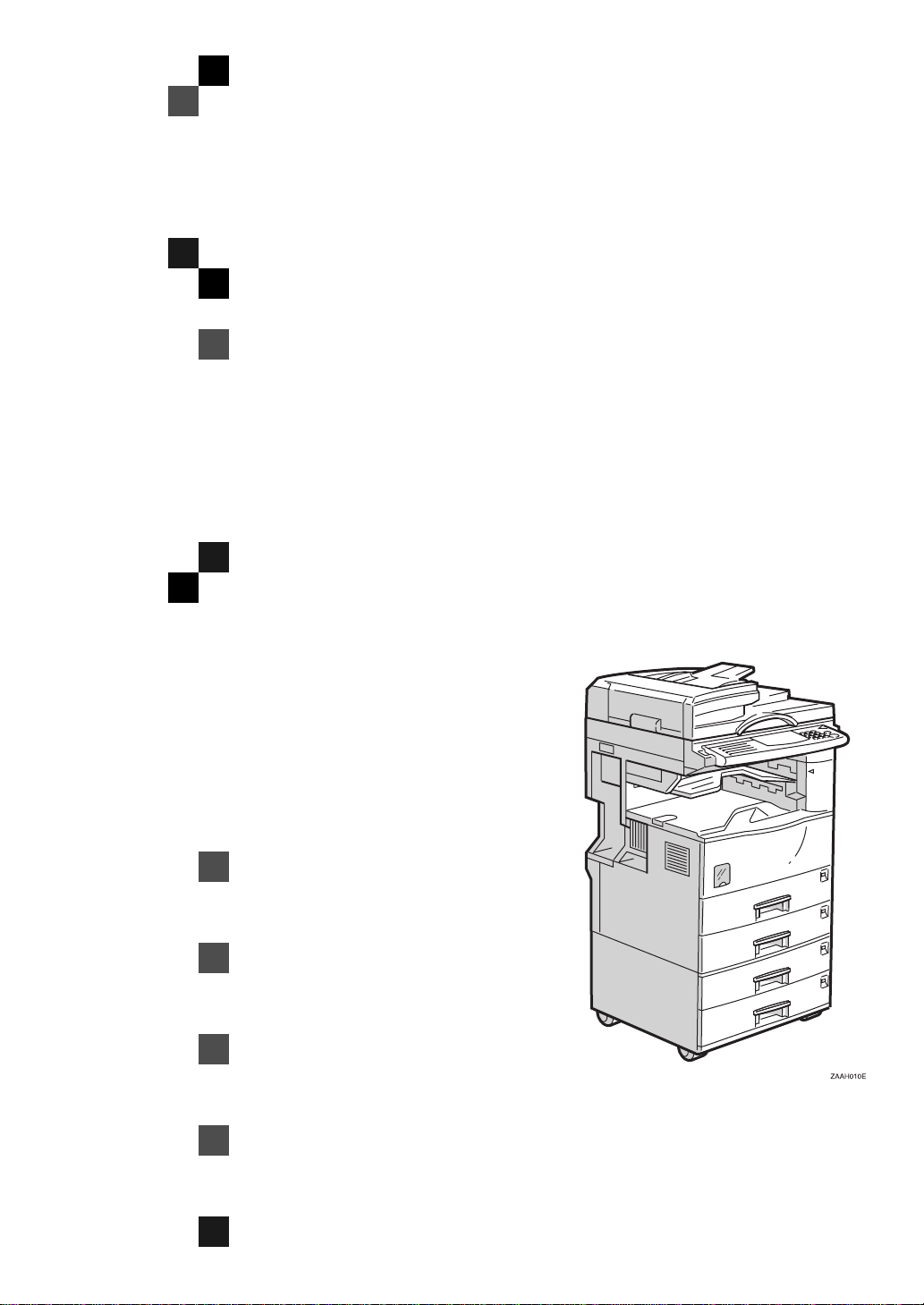
Available Options
• Fax Function Upgrade Unit (Fax Function Upgrade Type 185)
• Expansion Memory (32MB: DIMM)
• ISDN Unit (ISDN Option Type 270)
• Extra G3 Interface Unit (G3 Interface Unit Type 270)
Supplies
• Marker Ink (Marker Type 30)
Page 4

Declaration of Conformity
“The Product complies with the requirements of the EMC Directive 89/336/EEC and the Low Voltage
Directive 73/23/EEC.”
Page 5

NOTICE
R
CAUTION:
Use of controls, adjustments or performance of procedures other than those
specified herein may result in hazardous radiation exposure.
Shielded interconnect cables must be employed with this equipment to ensure
compliance with the pertinent RF emission limits governing this device.
CE 0682 X
The equipment has been approved in accordance with Council Decision 98/
482/EC for pan-European single terminal connection to the public switched telephone network (PSTN). However, due to differences between the individual
PSTNs provided in different countries, the approval does not, of itself, give an
unconditional assurance of successful operation on every PSTN network termination point. In the event of problems, you should contact your equipment supplier in the first instance.
98/482/EC:
* Council Decision of 20 July 1998 on a common technical regulation for the re-
quirements for connection to the analogue public switched telephone networks
(PSTNs) of terminal equipment (excluding terminal equipment supporting the
voice telephony justified case service) in which network addressing, if provided,
is by means of dual tone multi-frequency (DTMF) signaling.
Network compatibility declaration for the EU.
This Fax Option is designed to work in all EU countries by changing software
switch settings. Please contact your service representative if an option is moved
to other countries.
CE168X
“The ISDN kit complies with the requirements of Commission Decision 94/797/
EC”
94/797/EC:
Commission Decision of 18 November 1994 on a common technical regulation
for the pan-European integrated services digital network (ISDN) basic access.
Direct (or indirect) reflected eye contact with the laser beam may cause serious eye
damage. Safety precautions and interlock mechanisms have been designed to prevent
any possible laser beam exposure to the operator.
Note
❒ Some illustrations may be slightly different from your machine.
❒ Certain options may not be available in some countries. For details, please
contact your local dealer.
i
Page 6
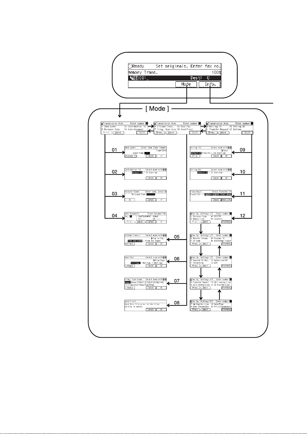
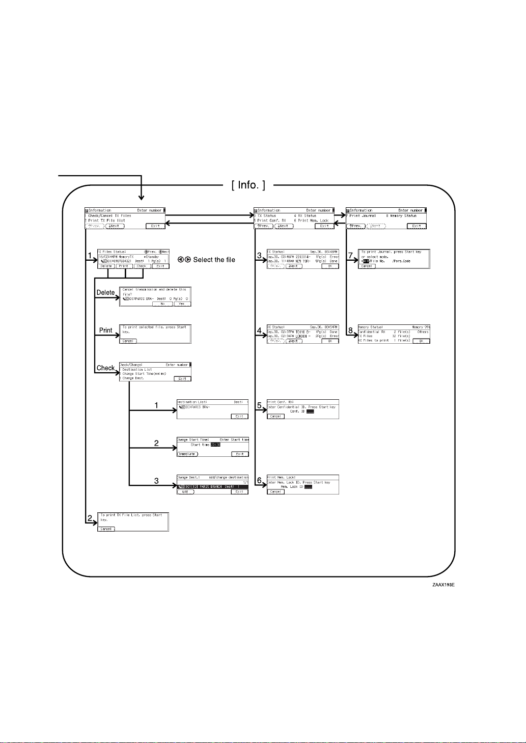
FUNCTION MAP
ii
Page 7
iii
Page 8

TABLE OF CONTENTS
1.Getting Started
GUIDE TO COMPONENTS ........................................................................ 1
Front View..................................................................................................... 1
Rear View...................................................................................................... 3
OPERATION PANEL.................................................................................. 4
STARTING THE MACHINE........................................................................ 7
Turning On The Power.................................................................................. 7
Turning Off The Power.................................................................................. 7
SWITCHING BETWEEN COPY MODE AND FACSIMILE MODE............. 9
READING THE DISPLAY......................................................................... 10
Reading the Display Panel and Using Keys................................................ 10
Standby Display.......................................................................................... 11
Communication Display .................... .......................................................... 11
Display Prompts.......................................................................................... 11
USEFUL FUNCTIONS.............................................................................. 12
Auto Fax Reception Power-up.................................................................... 12
Dual Access......... ....................................................................................... 12
Personal Code Access.............................. .................. ................... ............. 12
Checking Settings (Check Modes).............................................................. 13
Transmission with Image Rotation.............................................................. 13
Simultaneous Broadcast .............. .................................... ................... ........ 13
Multi-port........................................................... .......................................... 14
ACCEPTABLE TYPES OF ORIGINALS.................................................. 15
Acceptable Original Sizes........................................................................... 15
Original Sizes Difficult to Detect.................................................................. 16
Paper Size and Scanned Area.................................................................... 16
HOW TO SET AN ORIGINAL................................................................... 19
Setting a Single Original on the Exposure Glass........................................ 20
Setting Originals in the Document Feeder (ARDF)..................................... 21
WHERE INCOMING MESSAGE ARE DELIVERED—OUTPUT TRAY ... 22
When the Selected Output Tray Becomes Full........................................... 22
When the Finisher Unit is Installed.............................................................. 22
Tray Shift..................................................................................................... 22
2.Sending a Fax Message
OVERVIEW............................................................................................... 23
Overview........................................ ............................................................. 23
MEMORY TRANSMISSION...................................................................... 24
Memory Storage Report.............................................................................. 28
Transmission Result Report (Memory Transmission)................................. 28
Communication Failure Report ................................................................... 29
iv
Page 9

CANCELING A MEMORY TRANSMISSION............................................ 30
Canceling the Transmission Before the Original is Scanned In.................. 30
Canceling a Transmission While the Original is Being Scanned In ............ 30
Canceling a Transmission While the Message is Being Sent..................... 30
IMMEDIATE TRANSMISSION.................................................................. 32
Transmission Result Report (Immediate Transmission) ............................. 34
On-hook Dial............................................................................................... 34
Manual Dial ............................... .................................................................. 35
CANCELING AN IMMEDIATE TRANSMISSION..................................... 36
Canceling a Transmission Before You Have Pressed Start........................ 36
Canceling a Transmission After You Have Pressed the Start Key ............. 36
SCAN SETTINGS ..................................................................................... 37
Resolution................................................................................................... 37
Original Type............................................................................................... 38
Image Density (Contrast) .................................................................... ........ 38
Mixing Scan Settings in a Multiple Page Original........................................ 39
CHANGING THE LINE TYPE................................................................... 41
DIALING.................................................................................................... 43
Number Keys ........................................................................................... 44
Pause................................................ .......................................................... 45
Tone............................................................................................................ 45
Subaddress.................................................... ............................................. 46
Chain Dial.......................................... .......................................................... 46
Quick Dials.................................................................................................. 47
Speed Dials................................................................................................. 48
Groups ......................................... ............................................................... 50
Redial.......................................................................................................... 51
TRANSMISSION FEATURES................ ..... .... ............................ ..... ..... .... 52
Stamp................... .................................................................. ..................... 52
ID Transmission (Closed Network) ............................................................. 52
F Code (SUB).............................................................................................. 52
F Code (SID)............................................................................................... 53
JBIG Transmission.................................... .................................................. 54
3.Receiving a Fax Message
IMMEDIATE RECEPTION........................................................................ 55
MEMORY RECEPTION ............................................................................ 56
Substitute Reception............................................................................... 57
Screening Out Messages from Anonymous Senders ................................. 57
SELECTING THE RECEPTION MODE.................................................... 59
Facsimile Mode (Auto Reception Mode)..................................................... 59
Telephone Mode ......................................................................................... 59
RECEPTION FUNCTIONS........................................................................ 60
Transfer Station........................................................................................... 60
v
Page 10

Transfer Result Report................................................................................ 61
ID Reception (Closed Network)................................................................... 61
F Code (SEP)......................................... ..................................................... 61
F Code (PWD)............................................................................................. 63
JBIG Reception........................................... ................................................ 63
PRINTING FUNCTIONS ........................................................................... 64
Print Completion Beep................................................................................ 64
Checkered Mark........................... ............................................................... 64
Centre Mark ................................................................................................ 64
Reception Time............... ............................................................................ 64
Multi-copy Reception................................................................................... 65
2-Sided Printing........................................................................................... 65
180 Degree Rotation Printing...................................................................... 66
Image Rotation...................................................................................... ...... 66
Combine 2 originals ....................................... ............................................. 67
Page Separation and Length Reduction (not available in some countries)
Reverse Order Printing ............................................................................... 68
Page Reduction........................................................................................... 68
TSI Print............................... ....................................................................... 68
CIL/TID Print ..................................... .......................................................... 69
When There is No Paper of the Correct Size........................................ ...... 69
Having Incoming Messages Printed on Paper From the Bypass Tray........ 72
... 67
4.Advanced Transmission Features
OVERVIEW............................................................................................... 73
Overview........................................ ............................................................. 73
SEND LATER............................................................................................ 74
CONFIDENTIAL TRANSMISSION........................................................... 76
PERSONAL CODE TRANSMISSION....................................................... 78
SENDING AN AUTO DOCUMENT...................... ............................ ..... .... 79
2-SIDED TRANSMISSION (DOUBLE-SIDED TRANSMISSION) ............ 81
BOOK FAX................................................................................................ 83
CHOOSING THE AREA TO BE SCANNED YOURSELF
(IRREGULAR SCAN AREA)................................................................. 85
SEND FIRST............................................................................................. 87
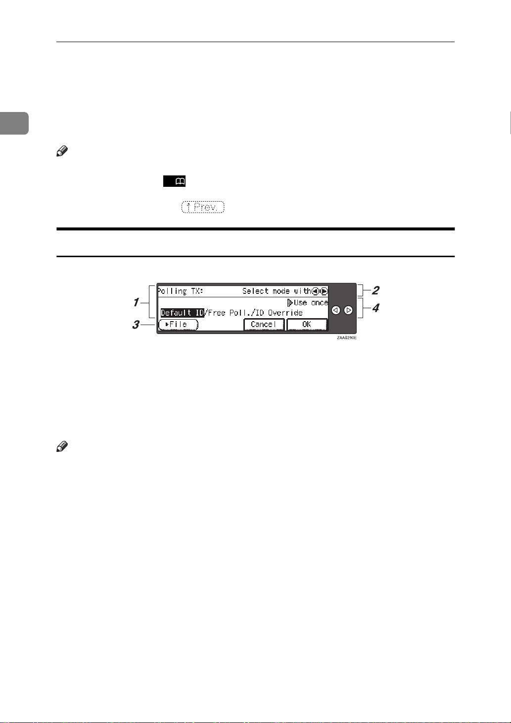
POLLING TRANSMISSION...................................................................... 88
Polling Transmission Clear Report.............................................................. 90
POLLING RECEPTION............................................................................. 91
Polling Reserve Report............................................................................... 92
Polling Result Report .................................................................................. 92
TRANSFER REQUEST............................................................................. 93
Specifying an End Receiver........................................................................ 95
TRANSMISSION OPTIONS.......................................... ..... ....................... 96
Selecting Transmission Options for a Single Transmission........................ 97
vi
Page 11

5.Communication Information
CHECKING AND CANCELING TRANSMISSION FILES ...................... 101
Canceling a Transmission......................................................................... 101
Printing a File............................................................................................ 102
Checking and Editing a File ...................................................................... 102
PRINTING A LIST OF FILES IN MEMORY (PRINT TX FILE LIST)....... 106
CHECKING THE TRANSMISSION RESULT (TX FILE STATUS)......... 107
CHECKING THE RECEPTION RESULT (RX FILE STATUS)............... 108
PRINTING A CONFIDENTIAL MESSAGE............................................. 109
Confidential File Report............................................................................. 110
PRINTING A FILE RECEIVED WITH MEMORY LOCK......................... 111
PRINTING THE JOURNAL..................................................................... 113
DISPLAYING THE MEMORY STATUS.................................................. 114
6.Troubleshooting
WHEN TONER RUNS OUT.................................................................... 115
ERROR MESSAGES AND THEIR MEANINGS..................................... 116
SOLVING PROBLEMS........................................................................... 117
INDICATORS.......................................................................................... 118
When the Receive File Indicator is Lit....................................................... 118
When (the Confidential File Indicator) is Lit or Blinking............................ 118
When the Facsimile Error Indicator is Lit in Red....................................... 119
WHEN AN ERROR REPORT IS PRINTED............................................ 120
WHEN POWER IS TURNED OFF OR FAILS......................................... 121
7.Facsimile User Tools
ACCESSING THE USER TOOLS........................................................... 123
Exiting User Tool mode............................................................................. 124
REGISTER/DELETE MENU ................................................................... 125
Registering Quick Dials ............................................................................. 125
Deleting Quick Dials .................................................................................. 127
Quick Dial Key and Function Key Label (Dial label).................................. 128
Registering Groups................................................................................... 130
Registering End Receivers for Multi-step Transfer ................................... 133
Deleting Groups........................................................................................ 136
Registering Speed Dials............................................................................ 138
Deleting Speed Dials................................................................................. 140
Storing Keystroke Programs..................................................................... 142
Deleting a Keystroke Program.................................................................. 145
Registering an Auto Document................................................................. 146
Deleting an Auto Document...................................................................... 148
vii
Page 12

Printing an Auto Document....................................................................... 150
Registering an Irregular Area.................................................................... 150
Deleting an Irregular Area......................................................................... 152
REPORTS/LISTS.................................................................................... 154
INITIAL SETUP TX ................................................................................. 156
INITIAL SETUP RX................................................................................. 158
To Set the Bypass Paper Size.................................................................. 160
ASSIGNING USER FUNCTION KEYS................................................. .. 161
Storing/Editing the Contents of a User Function Key................................ 161
Using a User Function Key ....................................................................... 162
Functions You Can Store In User Function Keys...................................... 163
KEY OPERATOR SETTINGS................................................................. 164
Personal Codes......................... ................................................................ 164
RTI/TTI...................................................................................................... 169
Memory Lock............................................................................................. 171
Counters.................................................................................................... 172
Monitor Volume......................................................................................... 173
Registering the Economy Transmission Time .......................................... 175
ID Code..................................................................................................... 176
Multistep Transfer ..................................................................................... 178
Special Senders to Treat Differently (Special RX Nos.)............................ 180
Authorized Reception................................................................................ 186
Forwarding................................................................................................ 190
ECM.......................................................................................................... 197
Transfer Report......................................................................................... 198
G3 Analog Line ......................................................................................... 200
G3 Digital Line........................................................................................... 201
G4 Digital Line........................................................................................... 203
Date/Time.................................................................................................. 205
Changing the User Parameters................................................................. 206
Summer Time............................................................................................ 213
Fax Auto Reset ......................................................................................... 213
Paper Feed Selection................................................................................ 214
RDS (Remote Diagnostic System)............................................................ 214
8.Entering Text
ENTERING AND MODIFYING TEXT...................................................... 215
Available Characters................................................................................. 215
Keys.......................................................................................................... 215
How To Enter Text.................................................................................... 216
9.Maintaining Your Machine
CONNECTING THE MACHINE TO A TELEPHONE LINE AND TELEPHONE
Connecting the Telephone Line ..................... .................. ......................... 219
Connecting the Machine to the ISDN ....................................................... 220
viii
... 219
Page 13

Selecting the Line Type............................................................................. 220
REPLACING THE STAMP CARTRIDGE............................................... 221
10.Appendix
OPTIONAL EQUIPMENT.............................................. ..... ..... .... ............ 223
Expansion Memory (32MB: DIMM)........................................................... 223
Fax Function Upgrade Unit....................................................................... 223
ISDN Unit (ISDN Option Type 270)........................................................... 224
Extra G3 Interface Unit (G3 Interface Unit Type 270)............................... 224
Duplex Unit (AD360)................................................................................. 224
PC-Fax Expander (PC-Fax Expander Type 185)...................................... 224
SPECIFICATIONS .................................................................................. 225
FUNCTION LIST..................................................................... .... ..... ..... .. 226
Advanced Transmission Features............................................................. 226
Communication Information...................................................................... 228
User Tools................................................................................................. 229
INDEX...................................................................................................... 233
ix
Page 14

x
Page 15
1. Getting Started
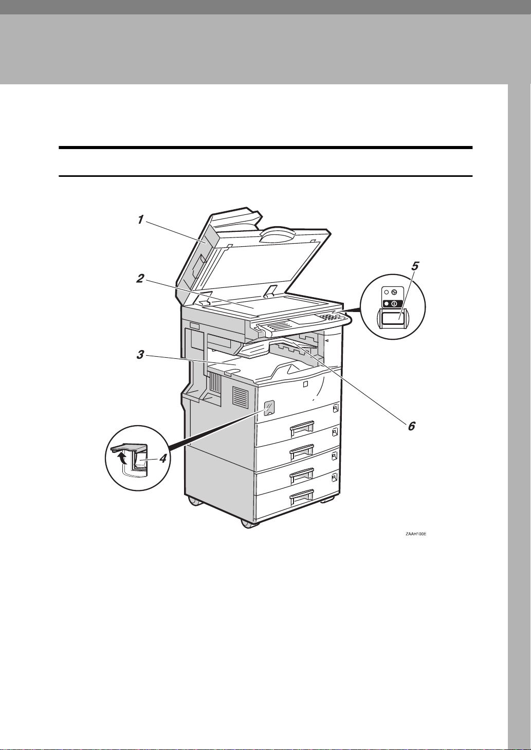
GUIDE TO COMPONENTS
Front View
1. Document Feeder (ARDF)/Platen
Cover
Holds a document stack of up to 50
sheets which are fed automatically one at
a time. Place documents face up here.
2. Exposure Glass
Place the original face down aligning its
upper left corner with the reference mark
at the upper left corner of the exposure
glass. Close the platen cover when you
set a document on the exposure glass.
3. Internal Tray
By default received fax messages are delivered here. Other trays can be selected
for prints or copies.
See “Changing the Machine's Settings” in
the System Settings manual.
4. Main Power Switch
Do not touch this switch. This switch
should be only used by a service representative.
1
Page 16

1
Getting Started
Note
If the Operation switch is on and there
❒
is still no power, turn on the
Power
If you leave the
❒
off for more than about an hour, all
files in memory are lost.
switch.
Main Power
Main
switch
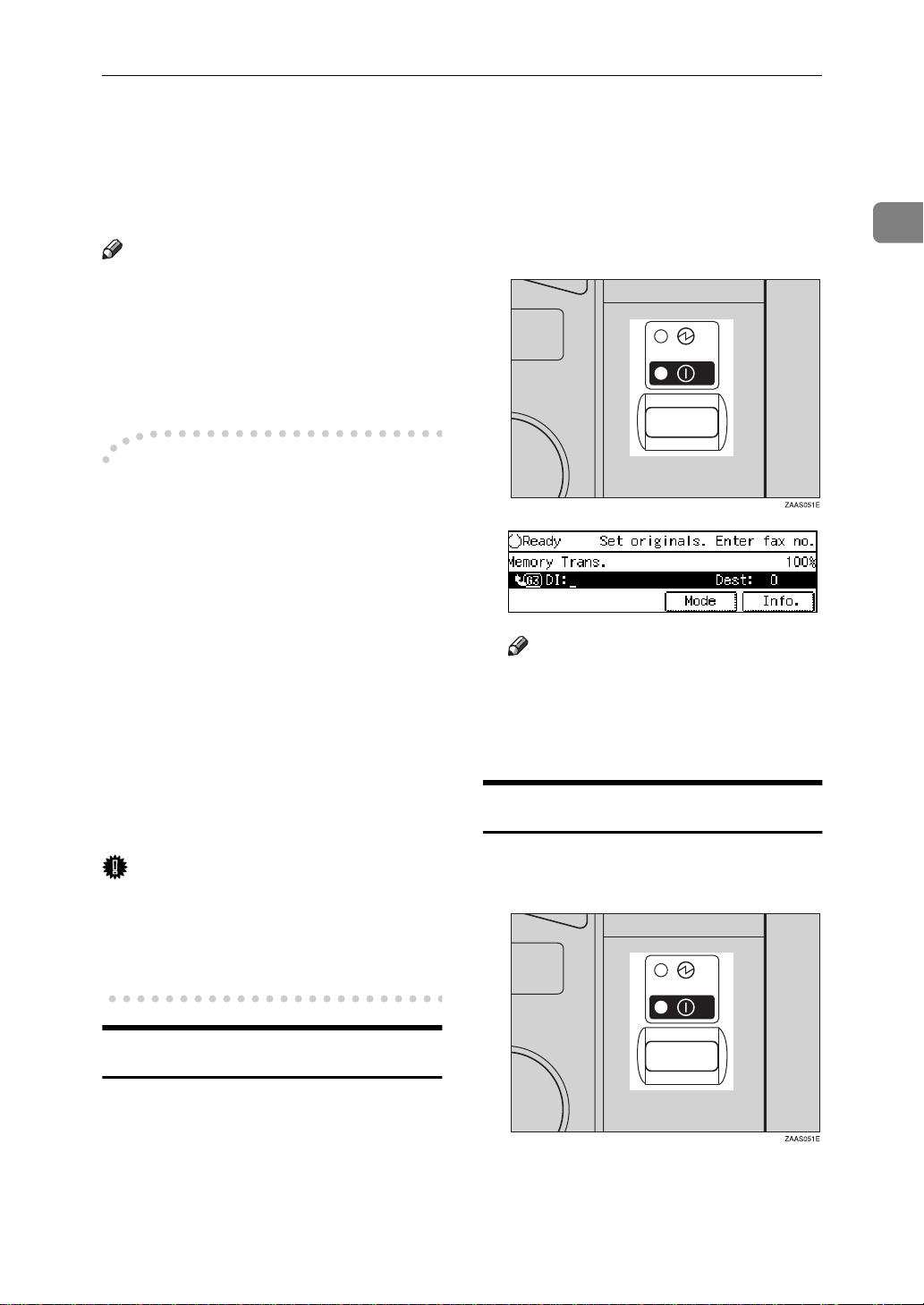
5. Operation Switch
Press this switch to turn the power on
(the On indicator lights up). To turn the
power off, press this switch again (the
indicator goes off).⇒ P.7
Power”
up”
OFF OR FAILS”
, P.12
, P.121
“Auto Fax Reception Power-
“WHEN POWER IS TURNED
“Turning On The
On
6. Internal Tray 2 (option)
You can chose to have prints or copies delivered here.
2
Page 17
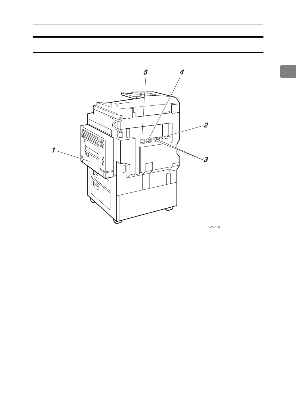
Rear View
GUIDE TO COMPONENTS
1
1. Bypass Tray
Select this tray for non-standard size paper.
See P.19
in the Copy Reference manual.
“HOW TO SET AN ORIGINAL”
2. Analog Line Connector
3. External Telephone Connector
4. Optional extra G3 Interface Unit
Connector
5. ISDN Line Connector ⇒ P.220
“Connecting the Machine to the ISDN”
3
Page 18
1
Getting Started
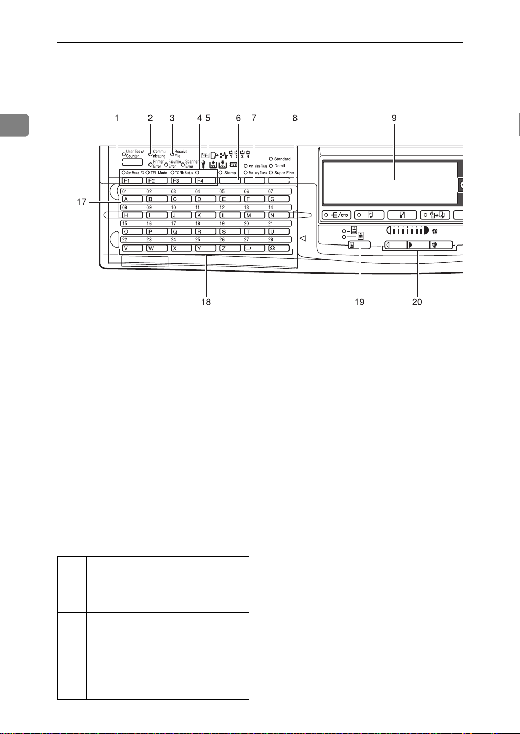
OPERATION PANEL
1.
{
User Tools/Counter
Press to enter User Tools mode. These
tools allow you to customize the default
settings.
key
}
2. Communicating Indicator
Lights during transmission or reception.
3. Receive File Indicator
Lights to tell you a message has been received into memory.
Note that this indicator does not inform
you of a Confidential reception.
4. User Function keys
Each of these can be programmed for
rapid access to frequently used features.
❖
Features Programmed by Default
Key Standard With the
ISDN Unit or
Extra G3 Unit
options
F1 Start Manual RX
F2 TEL Mode
F3 Transmission
Result Display
F4 - Line Selection
4
←
←
←
5. Confidential File Indicator
Blinks when a Memory Lock file has been
stored in memory.
Lights when a message has been received
into memory with Confidential Reception. ⇒ P.109
TIAL MESSAGE”
“PRINTING A CONFIDEN-
6. Stamp key
Press this key before sending a fax to
have a mark stamped on the scanned
document.
7. Transmission Mode key
Press the key to toggle between Memory
Transmission (
mediate Transmission (
Trans.
) modes.
Memory Trans.
) and Im-
Immediate
8. Resolution key
Press to switch between
and
Super Fine
Memory required).
Standard, Detail
(optional Expansion
9. LCD display
This guides you through tasks and informs you of the machine status. Messages appear here.
10. 0 1 keys
Press to move the cursor or select functions.
Page 19
OPERATION PANEL
1
key
}
key
}
key
}
}
key
}
key
key
}
{
Start
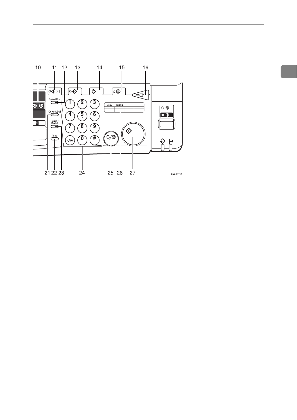
11.
{
Check Modes
Press this key before pressing the
key to check the settings selected for the
fax about to be sent.
12.
{
Speed Dial
Press to select a Speed Dial.
13.
{
Program
This key is used in Copy operation mode.
14.
{
Clear Modes
Cancels the current settings and returns
the machine to standby mode.
15.
{
Energy Saver
Hold down for more than a second to enter Energy Saver mode.
16.
{
Interrupt
Interrupts the current fax operation to
start copying.
17. Quick Dial Flip Plate
Flip this plate down to access Quick Dial
keys 01 through 28, flip up to access keys
29 through 56.
and
}
}
key
}
{
}
key
key
Darker
key
19.
{
Original Type
Use when sending a halftone image such
}
as a photograph or a color original.
20.
{
Lighter
{
Auto Image Density
Press this key to adjust the image density
of the scanned image.
21.
{
On Hook Dial
Use to dial a number from the numeric
keypad without having to lift the handset.
22.
{
Tone
Press to send tonal signals down a pulse
dialing line.
23.
{
Pause/Redial
Pause:
Inserts a pause when you are dialing or
storing a fax number. A pause cannot be
inserted as the first digit.
Redial:
Press to redial one of the last ten num-
bers.
key
}
}
keys and
}
18. Quick Dial keys
Use to dial numbers at a single touch or
to enter letters and symbols. Also use for
the Group Dial, Keystroke Program features.
24. Number keys
Use to dial fax numbers or enter the
number of copies.
5
Page 20

Getting Started
1
key
}
key
}
key
25.
{
Clear/Stop
Clear:
Deletes one character or digit.
Stop:
Interrupts the current operation (trans-
mission, scanning, copying or printing).
26.
{
Facsimile
P r e s s t o s w i t c h t o F a c s i m i l e m o d e .
27.
{
}
Start
Press to start all tasks.
6
Page 21
STARTING THE MACHINE
STARTING THE MACHINE
To start the machine, turn on the operation switch.
Note
❒ This machine automatically enters
Energy Saver mode or turns itself
off if you do not use the machine
for a while. See “08. Energy Saver
Timer”, “09. Auto Off Timer” in
the System Settings manual.
Power switches
-
This machine has two power switches: See P.1
NENTS”
❖
Operation switch
Turn on this switch to activate the
machine. When the machine has
warmed up, you can make copies
or send faxes.
❖
Main power switch
Do not touch the Main Power
switch. It should be used only by a
service representative when the
optional fax unit is installed.
“GUIDE TO COMPO-
B Turn on the operation switch. The
On indicator should light.
The panel display will turn on.
Note
❒ If nothing happens when you
turn on the operation switch,
make sure the Main Power
switch is turned on.
Turning Off The Power
1
Important
❒ If you leave the Main Power
switch off for more than one hour,
all fax files in memory are lost. See
“Turning Off The Power” below.
Turning On The Power
A Make sure that the power cord is
plugged into the wall outlet firmly and the Main Power switch is
on.
A Turn off the operation switch.
The On indicator will go out.
7
Page 22

1
Getting Started
Important
❒ Before you unplug the power
cord, make sure that the display
in Facsimile mode indicates that
the remaining memory space is
100%.
❒ Fax files stored in memory will
be lost an hour after you turn
the Main Power switch off or
you unplug the power cord. ⇒
P.121
TURNED OFF OR FAILS”
“WHEN POWER IS
8
Page 23
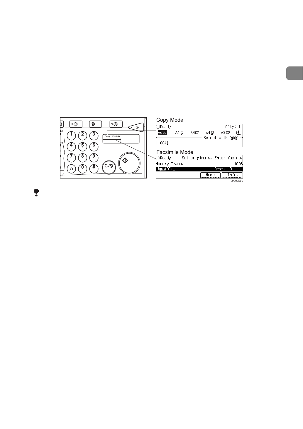
SWITCHING BETWEEN COPY MODE AND FACSIMILE MODE
SWITCHING BETWEEN COPY MODE AND
FACSIMILE MODE
You can use this machine both as a fax machine and a copier. Ordinarily when
you turn on the power switch, the copier screen is shown and you are ready to
make copies. When you wish to use fax functions, press the
the right of the operation panel.
Limitation
❒ You cannot switch modes under the following circumstances:
• While scanning in a fax
• During Immediate Transmission
• While editing the System Settings
• During Interrupt Copying
{
Facsimile
key on
}
1
• While using On-hook Dial
9
Page 24
Getting Started
READING THE DISPLAY
1
The display tells you the machine status and guides you through operations.
Note
❒ Functions that have been selected
are hilighted (e.g. ). Keys that
you can not select are shown with
a dashed outline (e.g. ).
A3
❒ All procedures in this manual as-
sume you are in Facsimile mode.
By default, when you turn the machine on it is in Copy mode. Press
the
{
Facsimile
simile mode. You can have the machine start in Facsimile mode. See
“Changing the Machine's Settings”
i n t h e S y s t e m S e t t i n g s m a n u a l .
Reading the Display Panel and Using Keys
1. Display for the currently selected function.
2. Machine status and messages.
key change to Fac-
}
3. Press these keys to navigate menu screens and confirm or cancel selections.
4. Press to select an item from a selection. The currently selected item is hi-
lighted.
Note
Press 0 to select the item one place to the left.
❒
Press 1 to select the item one place to the right.
❒
10
Page 25
READING THE DISPLAY
Standby Display
While the machine is in standby
mode (immediately after it is turned
on or after the
pressed), the following the display is
shown.
❖
Memory Transmission
❖
Immediate Transmission
Note
❒ To return the machine to standby
mode, do one of the following:
• If you have set an original and
are in the sending process, remove the original.
{
Clear Modes
key is
}
Note
❒ Even when the machine is sending
or receiving a fax message from/
into memory, you can still scan the
next original into memory. ⇒ P.12
“Dual Access”
❖
Immediate Transmiss i on :
Display Prompts
Depending on the situation, the machine will show various prompts on
the display.
❖
Instructions an d Requests
❖
Questions
1
• If you have not set an original
and are in the sending process,
press the
• If you are in User Tools mode,
press the
key.
{
Clear Modes
{
User Tools/Counter
key.
}
Communication Display
While the machine is communicating
the status is displayed.
❖
Display during Memory Transmission
or Memory Reception:
}
❖
Selections
❖
Status
11
Page 26
1
Getting Started
USEFUL FUNCTIONS
Auto Fax Reception Power-up
This machine can be set to shut down
automatically if nobody has used the
it for a while. In these situations, even
through the operation switch is off,
the machine can still receive incoming messages as long as the Main
Power switch is on.
Important
❒ Reception is not possible if both
the operation switch and Main
Power switch are turned off.
Note
❒ By default, messages are printed as
soon as they are received (Immediate Reception). To change this, see
P.206
ters”
“Changing the User Parame-
thorized people from sending fax
messages and can be used to track fax
machine use by giving a personal
code to each user.
Note
❒ You can store up to 20 personal
codes (up to 50 with optional Fax
Function Upgrade Unit installed).
❒ Register personal codes and turn
Personal Code Access on. The default setting is off. ⇒ P.164
tering Personal Codes”
“Personal Code Access”
❒ Even if Restricted Access is ena-
bled, the machine can receive and
print a fax message.
“Regis-
, P.167
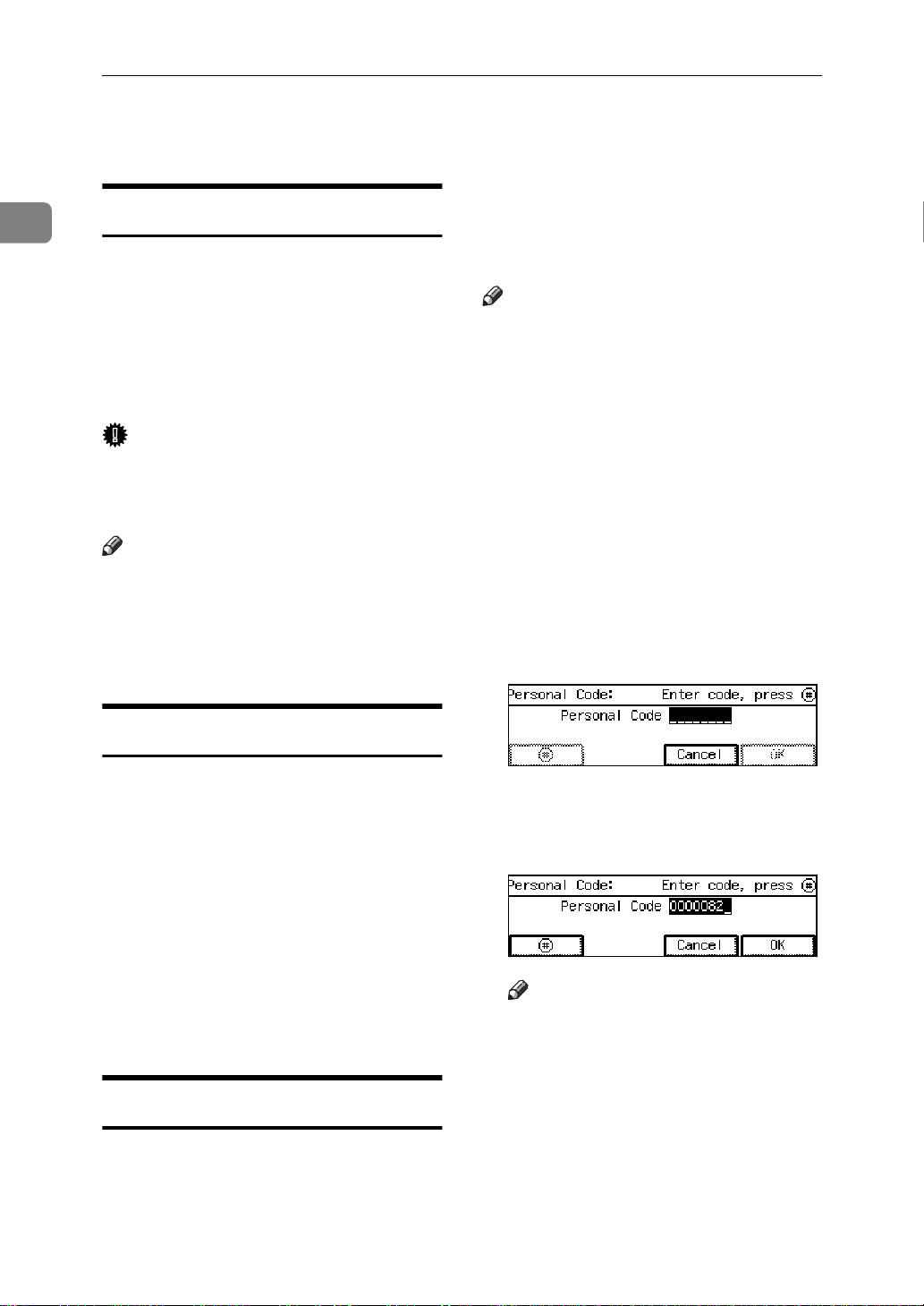
A If Personal Code Access is turned
on, the following display appears:
Dual Access
The machine can scan other messages
into memory even while sending a
fax message from memory, receiving
a message into memory , or automatically printing a report. Since the machine starts sending the second
message immediately after the current transmission terminates, the line
will be used efficiently.
Note that during Immediate Transmission or when in User Tools mode,
the machine cannot scan an original.
Personal Code Access
The machine can be set up so that nobody can use it without entering a
personal code. This prevents unau-
B Enter a personal code (8 digit
number) using the number keys,
and press
Note
❒ If a user enters a personal code
that is not registered, the machine returns to step A.
[#]
.
12
Page 27
USEFUL FUNCTIONS
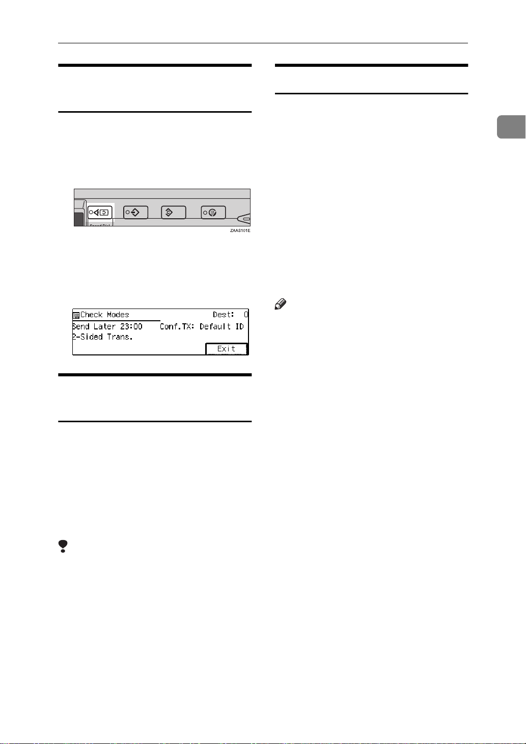
Checking Settings (Check
Modes)
Follow the steps below to view the
destinations and functions selected so
far.
A Press the
{
Check Modes
key.
}
B When you have finished check-
ing the settings, press the
key to return to the previ-
Modes
ous display.
}
Transmission with Image
Rotation
For most purposes, set A4/LT originals in the lengthwise direction (L).
If you set an A4/LT original in the
sideways direction (K), the image
will be sent rotated by 90°. Providing
the receiver has A4/LT lengthwise
paper (L), the message will be printed the same size as the original.
{
Check
Simultaneous Broadcast
The optional ISDN Unit or optional extra
G3 Interface Unit is required.
1
The Standard Broadcast feature sends
faxes one at a time to multiple destinations in the order that you specified
the destination numbers.
The Simultaneous Broadcast feature,
however, can send faxes two at a time
to multiple destinations by transmitting simultaneously over different
lines.
This results in a shorter overall transmission time.
Note
❒ This feature can use a maximum of
2 lines simultaneously.
❒ When using the optional extra G3
Interface Unit, if you set the line selection to “G3 Auto Select” beforehand, the machine will use
whichever G3 line is not busy
thereby increasing efficiency.
Limitation
❒ This feature is not available with
Parallel Memory Transmission or
Immediate Transmission.
❒ When Image Rotation is used, all
messages are sent by normal Memory Transmission.
13
Page 28

1
Getting Started
Multi-port
When the optional ISDN Unit or optional extra G3 Interface Unit is installed, communications can take
place simultaneously through two
lines at once.
Option Available
Line Types
Without option
PSTN G3
Available
Protocol
Combinations
❒ If two fax messages are received si-
multaneously, they cannot be
printed out at the same time.
❒ If two communications are in
progress, the display indicates the
first communication that was initiated.
❒ You can choose to have messages
received on a specified line printed
using paper from optional Internal
Tray 2. See the System Settings
manual for details.
Extra G3
Interface
Unit
ISDN
Unit
Extra G3
Interface
Unit+ISDN Unit
PSTN+PSTN G3+G3
PSTN+ISDN G3+G4
or
G3 (IS-
DN)+G4
ISDN G3 (IS-
DN)+G4
PSTN+PSTN
+ISDN
PSTN+ISDN G3+G4
G3+G3
or
G3+G4
or
G3 (IS-
DN)+G3
or
G3 (IS-
DN)+G4
Note
❒ A maximum of 2 communications
can take place simultaneously.
❒ You cannot perform 2 Immediate
Transmissions simultaneously.
14
Page 29

ACCEPTABLE TYPES OF ORIGINALS
ACCEPTABLE TYPES OF ORIGINALS
Make sure your originals are completely dry before setting them in the
machine. Originals containing wet
Acceptable Original Sizes
Where Original is
Set
Exposure glass Maximum A3
Document Feeder
(ARDF), single-sided document
Document Feeder
(ARDF), doublesided document
Acceptable Original Size Maximum
(297×420mm), 11"×17"
(279×432mm)
Fax transmission: A5 L to
A3 L (up to 1,200mm long)
1
8"×5
/2" L to 11"×47" (DLT)
L
Fax transmission: A5 L to
A3 L (up to 432mm long)
1
/2" L to 11"×17" (DLT)
8"×5
L
ink or correcting fluid will mark the
exposure glass and resulting image
will be affected.
Paper Thickness
Number of
Sheets
1 ----
50 sheets
(80g/m
50 sheets
(80g/m
2
2
, 20lb)
, 20lb)
40–128g/m
110kg, 11-34lb)
52–105g/m
90kg, 14–28lb)
2
(35–
2
(45–
1
Originals Unsuitable for the Document Feeder (ARDF)
Do not set the following types of originals in the Document Feeder (ARDF) because they may be damaged. Place them on the exposure glass instead.
• Originals of sizes other than those specified in the previous table
• Originals containing staples or clips
• Perforated or torn originals
• Curled, folded, or creased originals
• Pasted originals
• Originals with any kind of coating, such as thermosensitive paper, art paper,
aluminum foil, carbon paper, or conductive paper
• Originals with index tabs, tags, or other projecting parts
• Sticky originals, such as translucent paper
• Thin and soft originals
• Originals of inappropriate weight (see table above)
• Originals in bound form, such as books
• Transparent originals, such as OHP transparencies or translucent paper
15
Page 30
1
Getting Started
Original Sizes Difficult to Detect
The machine finds it difficult to detect the size of the following kinds of originals. If this happens, the receiving machine may not select print paper of the correct size. ⇒ P.18
• Documents set on the exposure glass of sizes other than those listed in the table below
• Originals with index tabs, tags, or projecting parts
• Transparent originals, such as OHP transparencies or translucent paper
• Dark originals with many characters or drawings
• Originals which partially contain solid printing
• Originals which have solid printing at their edges
The following paper sizes are automatically detected in Facsimile mode.
❖
Metric Version
“If the Machine Cannot Detect the Size of Your Original”
Paper size
Where original is placed
Exposure Glass
Document Feeder (AR-
DF)
A3 L,
1
/2"×13"
8"
(F4)
ΟΟΟΟ×
ΟΟΟΟΟ
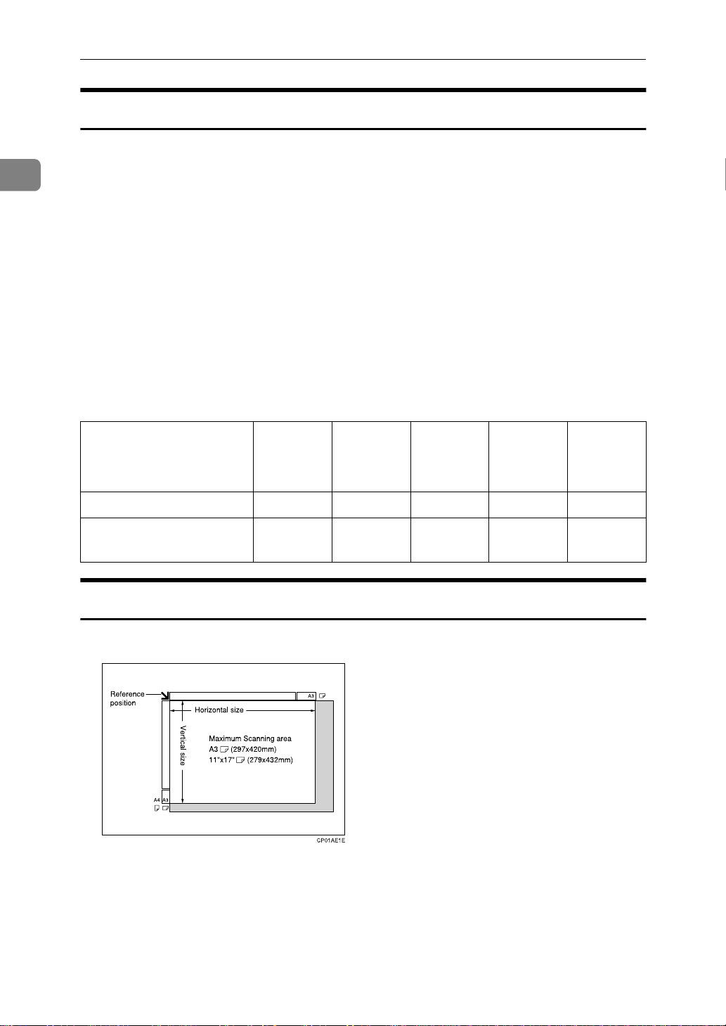
Paper Size and Scanned Area
❖
Exposure Glass
B4
L
A4 K
L
B5 K
L
A5
KL
16
Page 31

ACCEPTABLE TYPES OF ORIGINALS
❖
Document Feeder (ARDF)
Limitation
❒ There may be a difference in the size of the image when it is printed at the des-
tination.
❒ If you set an original larger than DLT/A3 on the exposure glass, only the
DLT/A3 area is scanned.
Note
❒ Even if an original is correctly placed on the exposure glass or in the Docu-
ment Feeder (ARDF), a margin of 3mm around each edge of the original may
not be sent.
1
❒ If the receiver uses paper narrower than the original, the image will be re-
duced to fit the paper width. ⇒ P.97
❒ The machine detects paper sizes in the following ways.
• When you set an original in the Document Feeder (ARDF), an original wid-
er than about 230mm is scanned as A4 size.
An original narrower than about 263mm will be sent as B4 size wide or A3
size.
Originals narrower than 190mm will be sent as A4 size.
Originals up to 1,200mm in length can be scanned.
Widths between 227 and 228mm cannot be identified correctly as widths
of A4 or B4 size.
• Refer to the table below for the sizes the machine can detect when you set
an original on the exposure glass. Because the machine scans in non-standard size documents as one of the standard sizes, parts of the image may be
truncated depending on the length of the document. For how to set nonstandard size documents, see ⇒ P.85
SCANNED YOURSELF (IRREGULAR SCAN AREA)”
“Auto Reduction”
“CHOOSING THE AREA TO BE
.
17
Page 32

Getting Started
Length
1
245mm not detect-
∼
width
245mm∼
270mm
270mm
Maximum Scan Area
-
245mm 245mm
∼
ed
B5
K
∼
A4
K
270mm
B5
L
not detect-ednot detect-ednot detect-
not detect-ednot detect-ednot detect-
∼
270mm∼
319mm
A4
L
319mm∼
344mm
1
8
/2"
×
13"
L
×
ed
ed
344mm
1
/2"
8
14"
L
×
B4
L
A3
L
Memory Transmission/Immediate Transmission
• From the Document Feeder (ARDF): 297×1,200mm (W×L)
• From the exposure glass: 297×432mm (W×L)
If the Machine Cannot Detect the Size of Your Original
If the machine cannot detect the original size, the following display is shown:
∼
If this happens, carry out the following steps.
A Press
[
Exit
.
]
B Remove the original and replace it on the exposure glass.
key to scan the original again.
}
Start
key again.
}
{
Start
18
C Press the
{
If the above display appears again, repeat step A to C.
Note
❒ If the machine still cannot detect the original size, the following display is
shown: If this happens, carry out the following steps.
• Press the 0 or 1 key to switch the scan size.
• Press the
Page 33

HOW TO SET AN ORIGINAL
HOW TO SET AN ORIGINAL
In this manual an original can mean a
single or multiple page document.
You can set your originals either in
the Document Feeder (ARDF) or on
the exposure glass. Some types of
originals are unsuitable for the Document Feeder (ARDF) so they must be
set on the exposure glass. ⇒ P.15
“ACCEPTABLE TYPES OF ORIGINALS”
Which way you place your original
depends on its size and whether you
are using the Document Feeder (ARDF) or the exposure glass.
Limitation
❒ If you set A5 size documents on
the exposure glass, they will not be
detected. Set A5 size documents in
the ARDF.
Note
❒ When sending a fax, the image
output at the other end depends on
the size and direction of paper
used in the receiver's terminal. If
the receiver does not use paper of
the same size and direction as that
of the original, the fax image may
be output reduced, trimmed at the
both edges, or divided into two or
more sheets. When sending an important original, we recommend
you to ask the receiver about the
size and direction of the paper
used in their terminal.
❒ When sending an original of an ir-
regular (i.e. non-standard) size or
part of a large original, you can
specify the scan area precisely. ⇒
P.85
“CHOOSING THE AREA TO
BE SCANNED YOURSELF (IRREGULAR SCAN AREA)”
❒ You can scan non-standard sized
documents as standard sized documents with the Irregular Scan
Area feature. When you turn on
this feature, the area scanned will
be in the specified range regardless
of the actual document size. A
blank margin will appear or the
image will be truncated at the receiving end.
❒ Make sure that all ink, correcting
fluid etc., has completely dried before setting your original. If it is
still wet, the exposure glass will be
marked and those marks will appear on the received image.
❒ If you set an A4 size original in the
sideways direction, the machine
rotates the image by 90 degrees before sending it. ⇒ P.13
sion with Image Rotation”
Reference
For how to set 2-sided documents,
see P.83
“BOOK FAX”
“Transmis-
.
1
19
Page 34

1
Getting Started
How to set A4, B4, A3, LT, LG
-
and DLT size originals
How to set A4, A5 and B5 size
-
originals
A Lift the Document Feeder (ARDF)
by at least 30 degrees. Place the
original face down and align its
upper left corner with the reference mark at the upper left corner
of the exposure glass.
1. Reference mark
2. Scale
Limitation
❒ A5 size on the exposure glass is not
detected. Set A5 size documents in
the ARDF.
Setting a Single Original on
the Exposure Glass
Set originals that cannot be placed in
the Document Feeder (ARDF), such
as a book, on the exposure glass one
page at a time.
Note
❒ If you do not raise the Docu-
ment Feeder (ARDF) by at least
30 degrees, the original size will
not be detected.
B Close the Document Feeder (AR-
DF).
Note
❒ When sending a bound original,
the received image may contain
some black areas. To reduce this
effect, hold down the original to
prevent its bound part from rising.
Bound Original Page Order
-
When sending bound originals
(books, magazines, etc.), you can
choose to have either the left page or
right page sent first.
20
Page 35

HOW TO SET AN ORIGINAL
Note
❒ The default setting is Send Left
Page first. ⇒ P.206
User Parameters”
“Changing the
Setting Originals in the
Document Feeder (ARDF)
Use the Document Feeder (ARDF) to
scan in a stack of originals in one operation. The Document Feeder (ARDF) can handle both single-sided and
double-sided originals.
Limitation
❒ The maximum document length is
1,200mm.
❒ Place all the originals to be sent in
a single stack.
❒ You cannot set originals in the
Document Feeder (ARDF) one
page at a time or in sheaves.
❒ Do not open the Document Feeder
(ARDF) while it is scanning the
originals or your document could
be jammed.
Note
❒ If you send the documents longer
than 1,200mm, select Long Document mode with the User Parameters. If a jam occurs, the document
might be damaged because scanning will not stop.
❒ If an original jams, press the
key then remove the original
}
Stop
carefully.
{
Clear/
Reference
For information about the sizes
and number of originals that can
be placed in the Document Feeder
(ARDF), see P.15
TYPES OF ORIGINALS”
“ACCEPTABLE
.
A Adjust the document guide to
match the size of your originals.
Align the edges of your originals
and stack them in the Document
Feeder (ARDF) face up.
1. Limit mark
2. Document guide
Important
❒ To avoid documents being in-
correctly detected by the sensors (1 in the diagram below),
do not place any foreign objects
on the document feeder or cover it with your hand.
1
❒ If your original is bent or folded,
flatten it before you set it.
❒ Set thin originals on the exposure
glass.
21
Page 36

Getting Started
WHERE INCOMING MESSAGE ARE
DELIVERED—OUTPUT TRAY
1
To change where incoming messages
are delivered, adjust the Output Tray
setting in the System Settings.
When the Selected Output
Tray Becomes Full
If you install the optional Finisher
Unit, the machine automatically detects when the selected Output Tray
becomes full. When this happens, a
warning will appear on the display
and the message will be received using Substitute Reception.
When the Finisher Unit is
Installed
You can use the optional Finisher
Unit for large capacity paper delivery
and sort delivery.
Limitation
❒ If you have selected the optional
Finisher Unit as the Output Tray
and a copy document longer than
13.3” (340mm) is left in the Finisher Unit, incoming messages are automatically delivered to the
Internal Tray.
Tray Shift
The optional Finisher Unit is Required.
When the optional Finisher Unit is selected for fax output, you can use the
Tray Shift function to have the internal delivery exit move to the left or
right whenever a fax or report is
printed.
This is useful for separating faxes
stacked in the finisher output tray,
e.g. if the previous incoming fax was
output to the left, the next incoming
fax will be output to the right and
vice-versa.
Note
❒ You can turn this feature on or off
with the User Parameters. When
the machine is shipped, this feature is turned on by default. ⇒
P.206
ters”
“Changing the User Parame-
Note
❒ If you receive messages larger than
12.9” (330mm) on a regular basis,
we recommend that you choose an
Output Tray setting other than Internal Tray.
22
Page 37

2. Sending a Fax Message
OVERVIEW
Overview
The basic procedure to send a fax
message is:
A Make sure the Facsimile indicator
is lit
B Set your original
C Dial the number
D Press the
The rest of this section describes these
steps and the various features that are
available in more detail.
There are two ways to send a fax message:
• Memory Transmission
• Immediate Transmission
Check the indicators on the operation
panel to check which mode is currently active and press the Transmission
Mode key to toggle between them.
{
Start
}
key
23
Page 38

Sending a Fax Message
MEMORY TRANSMISSION
2
In Memory Transmission mode, after
you press the
doesn't dial the destination until all
pages of your fax message have
scanned into memory (in contrast
with Immediate Transmission, where
the number is dialed first and pages
are scanned and sent one by one).
Memory Transmission is useful because:
• You can take your original away
from the machine without having
to wait too long
• While your message is being sent,
other people can operate the machine
• You can send the same message to
more than one place in a single operation (Broadcasting)
Important
❒ If there is a power failure (Main
Power switch is off) or the plug is
pulled out for more than 1 hour, all
the files stored in memory are deleted. As soon as power is restored,
the Power Failure Report is printed to help you identify deleted
files. If you turn just the operation
switch off, files are not deleted. ⇒
P.121
TURNED OFF OR FAILS”
Limitation
❒ If memory is full (0% appears on
the display), Memory Transmission is disabled. Use Immediate
Transmission instead.
Note
❒ Maximum number of Memory
Transmission files: 200 (up to 1,000
files with optional Fax Function
Upgrade Unit installed)
{
“WHEN POWER IS
key, the machine
}
Start
❒ Maximum number of destinations
per Memory Transmission: 256 (up
to 500 destinations with optional
Fax Function Upgrade Unit installed)
❒ Combined total number of desti-
nations that can be stored: 300 (up
to 2,000 destinations with optional
Fax Function Upgrade Unit installed)
❒ The theoretical maximum number
of destinations you can enter with
the number keys is 100, but this
will depend on the amount of
memory currently available (1,000
destinations with optional Fax
Function Upgrade Unit installed).
❒ The number of pages that you can
store in memory depends on the
original images and the scan settings. You can store up to 160
standard pages (ITU-T #1 chart,
Resolution: Standard, photo mode:
OFF).
❒ As default, the machine will return
to the default transmission mode
(Memory Transmission) after every transmission. You can change
this so that the current mode is
maintained. ⇒ P.206
User Parameters”
❒ The maximum total number of
documents that can be stored in
memory is as follows:
• About 400 pages with only the
optional Expansion Memory installed
• About 2,400 pages with both the
optional Expansion Memory
and Fax Function Upgrade Unit
installed
“Changing the
24
Page 39

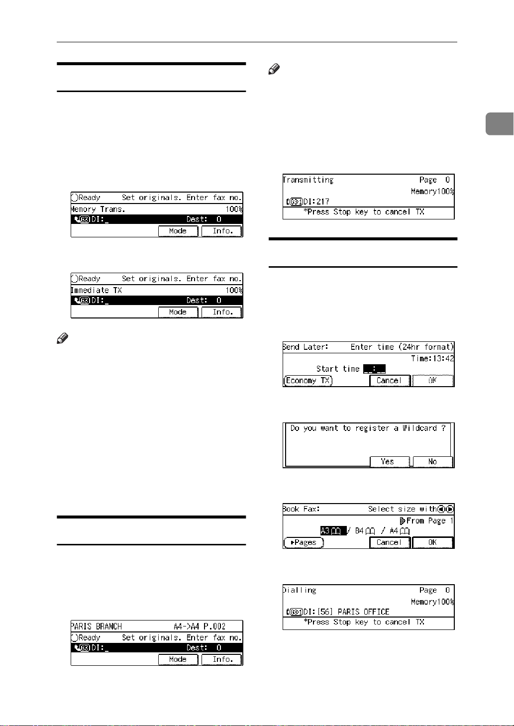
MEMORY TRANSMISSION
A Make sure that the Memory
Transmission indicator is lit.
If it isn't, press the
key.
}
Mode
{
Transmission
B Set the original.
Limitation
❒ You can send the first pages
from the exposure glass then
the remaining pages from the
Document Feeder (ARDF). After you place the last page on
the exposure glass, you have 60
seconds to insert the remaining
pages in the Document Feeder
(ARDF).
❒ Note that you cannot set pages
on the exposure glass after you
have started using the Document Feeder (ARDF).
❒ Do not open the Document
Feeder (ARDF) while it is scanning in originals.
Note
❒ Place the original you want to
store in memory on the exposure glass or the Document
Feeder (ARDF). To store multiple page originals from the exposure glass, set them page by
page.
❒ You can scan half the pages of
your original from the exposure
glass and the remainder from
the Document Feeder (ARDF).
When you have finished scanning from the exposure glass,
place the rest of the pages in the
Document Feeder (ARDF) and
press the
{
Start
key.
}
❒ The original can be placed at
any time up until you press the
key.
}
{
Start
Reference
P.19
“HOW TO SET AN ORIGI-
NAL”
C Select any scan settings you re-
quire. ⇒ P.37
“SCAN SETTINGS”
D Dial. If you wish to send the same
message to more than one destination, press
er destination. Repeat this step
for all destinations.
If you make a mistake, press the
key and enter the cor-
{
Clear/Stop
rect number again.
Note
❒ When specifying a destination
using a Quick Dial, Speed Dial
or Group dial, the destination is
added even if you did not press
[
Add
❒ When dialing with the number
keys or using Chain Dial (P.46
“Chain Dial”
line type (G3 or G4) before
pressing
❒ If you do not set an original
within 30 seconds of entering a
destination fax number, the
transmission is cancelled.
Reference
P.43
}
.
]
[
Add
“DIALING”
and dial anoth-
[
]
Add
), you can select the
in step D.
]
2
25
Page 40

Sending a Fax Message
2
E Press the
The machine starts scanning the
original.
The machine calls the destination.
The name or fax number which is
programmed as the RTI or CSI at
the other end is shown on the display.
Reference
P.169
After transmission, the machine
will return to standby mode.
{
“RTI/TTI”
Start
key.
}
D Set the next original on the ex-
posure glass within 60 seconds
after the machine has finished
scanning the first original.
Note
❒ Repeat steps C to D for all
pages.
E Set the last original then press
.
[#]
F Press the
The machine starts to call the
destination.
Checking the Transmission
-
{
Start
key.
}
Result
• Turn the Transmission Result Report on if you want a report to be
printed after every successful
transmission. ⇒ P.24
TRANSMISSION”
If you leave the Transmission Result Report off, the report will not
be printed after every transmission. However, should a transmission fail, a Communication Failure
Report will be printed instead.
“MEMORY
26
Sending Originals from the
Exposure Glass
A Set the first page of your origi-
nal on the exposure glass face
down.
B Dial.
C Press the
The machine starts scanning the
original.
{
Start
key.
}
• If you turn the Transmission Result Report (Memory Transmission) off, the Error Report will be
printed when the communication
on fails.
• You can also check the transmission result by examining the Journal. ⇒ P.113
JOURNAL”
You can either print or scroll
through the Journal on the display.
⇒ P.107
TRANSMISSION RESULT (TX
FILE STATUS)”
“PRINTING THE
“CHECKING THE
Page 41

Sending a Fax Message
-
Immediately
To send a fax message immediately,
use Immediate Transmission. If you
have just set up an original for broadcasting, Immediate Transmission will
interrupt the current communication.
If there are files queued in addition to
the file being currently sent, your
original is not be sent until the
queued files have been sent.
Automatic Redial
-
If a fax message could not be transmitted because the line was busy or
an error occurred during transmission, redialing is done several times at
certain intervals (these figures vary
according to which country you are
in).
If redialing fails after four redials, the
machine cancels the transmission and
prints the Transmission Result Report
or Communication Failure Report. ⇒
P.28
(Memory Transmission)”
munication Failure Report”
“WHEN POWER IS TURNED OFF
OR FAILS”
“Transmission Result Report
, P.29
“Com-
, P.121
MEMORY TRANSMISSION
specify four destinations A through D
for broadcasting, and if the lines to
destinations A and C are busy, the
machine dials the destinations in the
following order: A, B, C, D, A, and C.
When the optional ISDN Unit or optional extra G3 Interface Unit is installed, you can broadcast
simultaneously on multiple lines.
Checking the Transmission
-
Progress
To check which destinations the fax
message has been sent to so far, print
the TX file list. ⇒ P.106
LIST OF FILES IN MEMORY (PRINT
TX FILE LIST)”
If Memory Runs Out While
-
“PRINTING A
Storing an Original
If you run out of memory while storing an original (free space reaches
0%),
“Memory full” is displayed.
Press
es only.
to transmit the stored pag-
[
]
Exit
2
Broadcasting Sequence
-
If you dial several destinations for the
same message (Broadcasting) the
messages are sent in the order in
which they were dialed. If the fax
message could not be transmitted, the
machine redials that destination after
the last destination specified for
Broadcasting. For example, if you
Note
❒ By default, successfully scanned
pages are sent. If you wish to
change this setting, please contact
your service representative.
27
Page 42

Sending a Fax Message
2
Batch Transmission
-
If you send a fax message by Memory
Transmission and there is another fax
message waiting in memory to be
sent to the same destination, that
message is sent along with your original. Several fax messages can be sent
with a single call, thus eliminating the
need for several separate calls. This
helps save communication costs and
reduce transmission time.
Fax messages for which the transmission time has been set in advance are
sent by batch transmission when that
time is reached.
Note
❒ By default Batch Transmission is
switched on. You can switch it on
or off with the User Parameters. ⇒
P.206
ters”
“Changing the User Parame-
Memory Storage Report
This report is printed after an original
is stored in memory. It helps you review the contents and the destinations of stored originals. Even if the
machine is set up not to print this report, it is still printed if an original
could not be stored.
Note
❒ You can turn this report on and off.
By default it is not printed. ⇒ P.206
“Changing the User Parameters”
❒ You can choose whether to include
part of the original image on the report (part of the image is printed
by default). ⇒ P.206
User Parameters”
“Changing the
Transmission Result Report
(Memory Transmission)
ECM (Error Correction Mode)
-
This feature automatically resends
data that wasn't transmitted successfully using a system that complies
with international standards.
ECM requires that the destination
machine has the same feature.
Note
❒ By default ECM is switched on.
You can change this with the Key
Operator Settings. ⇒ P.164
OPERATOR SETTINGS”
“KEY
This report is printed when a Memory Transmission is completed so you
can check the result of the transmission. If two or more destinations are
specified, this report is printed after
the fax message has been sent to all
the destinations. If the machine is set
up not to print this report and the fax
message could not be successfully
transmitted, the Communication Failure Report is printed. ⇒ P.29
munication Failure Report”
Note
❒ By default this function is turned
on. You can turn it off with the
User Parameters. ⇒ P.206
ing the User Parameters”
❒ You can choose whether to include
part of the original image on the report (by default, part of the image
is printed).⇒ P.206
User Parameters”
“Changing the
“Com-
“Chang-
28
Page 43

❒ The “Page” column gives the total
number of pages. The “Not Sent”
column gives the number of pages
that could not be sent successfully.
Communication Failure Rep ort
MEMORY TRANSMISSION
This report is only printed if the
Transmission Result Report is turned
off and a message could not be successfully transmitted with Memory
Transmission. Use it to keep a record
of failed transmissions so you can
send them again.
Note
❒ You can choose whether to include
part of the original image on the report (by default, part of the image
is printed). ⇒ P.206
User Parameters”
❒ The “Page” column gives the total
number of pages. The “Not Sent”
column gives the number of pages
that could not be sent successfully.
“Changing the
2
29
Page 44

Sending a Fax Message
CANCELING A MEMORY TRANSMISSION
2
Canceling the Transmission
Before the Origin al is Scanned
In
A Press the
Note
❒ When you set the document in
the Document Feeder (ARDF),
you can cancel the transmission
by just removing it.
{
Clear Modes
key.
}
Canceling a Transmission
While the Original is Being
Scanned In
A Press the
{
Clear/Stop
key.
}
Canceling a Transmission
While the Message is Being
Sent
Use this procedure to cancel a transmission after the original has been
scanned in.
Limitation
❒ If transmission finishes while you
are carrying out this procedure, it
will not be canceled.
Note
❒ If you cancel a message while it is
being sent, transmission is halted
as soon as you finish this procedure. However, some pages of
your message may have already
been sent and will be received at
the other end.
A Press
[
Info.
.
]
30
The machine will stop storing the
original and the data will not be
sent.
The Information menu is shown.
B Enter the “Check/Cancel TX
Files” function number with the
number keys.
Note
❒ If “Check/Cancel TX Files” is
not shown, press
.
]
ext
↑
[
Prev.
]
or
↓
[
N-
Page 45

C Press the 0 or 1 key until the file
you wish to delete is shown and
press
[
Delete
.
]
CANCELING A MEMORY TRANSMISSION
D Press
The file is erased.
E Press
Note
❒ To delete another file, repeat
steps C and D.
F Press
[
Yes
[
Exit
[
Exit
.
]
.
]
.
]
2
31
Page 46

Sending a Fax Message
IMMEDIATE TRANSMISSION
2
With Immediate Transmission, when
you press the
number is dialed straight away (i.e.
immediately). The message is
scanned and transmitted page by
page without being stored in memory. This contrasts with Memory
Transmission which scans in all pages
into memory before dialing the destination.
Immediate Transmission is useful if
you want immediate confirmation
that the message is being sent to the
correct destination (just check the other terminal's RTI or CSI on the operation panel during transmission).
Note
❒ You cannot send the same message
to multiple destinations (Broadcasting). Use Memory Transmission for this purpose.
❒ Place the original on the exposure
glass or in the Document Feeder
(ARDF). To send two or more pages from the exposure glass, set
them one page at a time.
❒ You can scan some pages of your
original from the exposure glass
and the remainder from the Document Feeder (ARDF). When you
have finished scanning from the
exposure glass, place the remainder of the pages in the Document
Feeder (ARDF) and press the
{
❒ By default, the transmission mode
selected when the machine is
turned on or when modes are
cleared (transmission mode home
setting) is Memory Transmission.
You can change this with the User
Parameters. ⇒ P.206
User Parameters”
key within ten seconds.
}
Start
{
key, the fax
}
Start
“Changing the
A Check that the Immediate Trans-
mission indicator is lit.
If it is not lit, press the
key.
sion Mode
}
{
Transmis-
B Set your original.
Limitation
❒ Do not open the Document
Feeder (ARDF) while it is scanning the originals. This can
cause originals to jam.
Note
❒ You can set the original any
time up until you press the
key.
}
{
Start
Reference
P.19
“HOW TO SET AN ORIGI-
NAL”
C Select any scan settings you re-
quire. ⇒ P.37
“SCAN SETTINGS”
D Dial.
If you make a mistake, press the
{
Clear/Stop
rect number again.
Note
❒ If you are dialing with the
number keys or Chain Dial, you
can select the type of line you
want (G3 or G4). ⇒ P.46
Dial”
key and enter the cor-
}
“Chain
32
Page 47
IMMEDIATE TRANSMISSION
Reference
P.43
“DIALING”
P.41
“CHANGING THE LINE
TYPE”
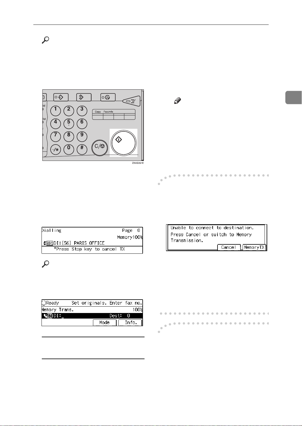
E Press the
The machine calls the destination.
While it is dialing, the number or
name which is programmed as the
RTI or CSI in the machine of the
other party is shown on the display. When connected, the machine starts scanning the original.
{
Start
key.
}
C Press the
The machine starts scanning the
original.
D Set the next original on the ex-
posure glass within 10 seconds
after the machine has finished
scanning the first original.
Note
❒ Repeat steps C to D for all
originals.
E Set the last original then press
[#]
F Press the
The machine starts to call the
destination.
If the Connection Could Not Be
-
{
.
{
Start
Start
key.
}
key.
}
Made
The following display appears if the
fax could not be sent:
2
Reference
P.169
“RTI/TTI”
After transmission the machine
will return to standby mode.
Sending Originals from the
Exposure Glass
A Set the first page face down on
the exposure glass.
B Dial.
Do one of the following:
• Press
• Press
-
This feature automatically sends data
that wasn't transmitted successfully
again using a technique called ECM,
an internationally recognized protocol (requires that the destination machine has the same feature).
[
Cancel
[
Memory TX
chine scan in the document and
then automatically redial the
number.
ECM (Error Correction Mode)
and try again.
]
to have the ma-
]
33
Page 48

Sending a Fax Message
2
Note
❒ By default, ECM is on. You can
turn it off. ⇒ P.197
“ECM”
Transmission Result Repor t
(Immediate Transmission)
If you turn this report on, a report will
be printed after every Immediate
Transmission so you have a record of
whether the transmission was successful or not. If the machine is set up
not to print this report and the fax
message could not be successfully
transmitted, the Error report is printed instead.
Note
❒ You can switch this report on or off
using the User Parameters. ⇒
P.206
ters”
❒ If the page was sent successfully,
the Page column gives the total
number of pages that were sent
successfully. The Not Sent column
gives the number of pages that
could not be sent successfully.
“Changing the User Parame-
❒ On-hook Dial does not work with
ISDN lines.
❒ This feature is not available for the
optional extra G3 Interface Unit.
Reference
P.173
“Monitor Volume”
A Set your original and select any
scan settings you require.
Reference
P.19
“HOW TO SET AN ORIGI-
NAL”
P.37
“SCAN SETTINGS”
B Press the
You will hear a low tone from the
internal speaker. If you wish to
cancel this operation, press the
Hook Dial
{
On Hook Dial
key again.
}
key.
}
{
On
On-hook Dial
This is just like using the external telephone, except you do not have to
pick up the external telephone before
dialing. Just press the
key and dial the number. If you hear
a voice, you can pick up the external
telephone and speak with the other
party.
Limitation
❒ This feature is not available in
some countries.
34
{
On Hook Dial
}
C Dial.
The machine immediately dials the
destination. If you make a mistake,
press the
key and return to step B.
}
Modes
{
On Hook Dial
or
}
{
Clear
Page 49

IMMEDIATE TRANSMISSION
D When the line is connected and
you hear a high-pitched tone,
press the
• If you hear a voice, pick up the
external telephone before you
press the
the destination that you want to
send a fax message (ask them to
switch to Facsimile mode).
• After transmission the machine
will return to standby mode.
{
Manual Dial
The external telephone is required.
Start
{
key.
}
key and notify
}
Start
A Set your original and select any
scan settings you require.
Reference
P.19
“HOW TO SET AN ORIGI-
NAL”
P.37
“SCAN SETTINGS”
B Pick up the external telephone.
You will hear a tone.
C Dial.
If you make a mistake, replace the
external telephone and try again
from step B.
D When the line is connected and
you hear a high-pitched tone,
press the
fax message.
{
key to send your
}
Start
2
Pick up the handset of the external
telephone and dial. When the line is
connected and you hear a highpitched tone, press the
send your fax message. If, on the other hand, you hear a voice at the other
end, continue your conversation as
you would normally over the telephone.
Limitation
❒ Manual Dial does not work with
ISDN lines.
❒ This feature is not available for the
optional extra G3 Interface Unit.
❒ The result of the transmission with
manual dial is not mentioned in
the Transmission Result Report
(Immediate Transmission).
{
Start
key to
}
E Replace the handset of the exter-
nal telephone.
After transmission the machine
will return to standby mode.
35
Page 50

Sending a Fax Message
CANCELING AN IMMEDIATE
TRANSMISSION
2
Canceling a Transmission
Before You Have Pressed Start
Use this procedure to cancel a transmission before you have pressed the
key.
}
{
Start
A Press the
Note
❒ When you have already set the
original, you can also cancel an
Immediate Transmission by removing the original from the
machine.
{
Clear Modes
key.
}
Canceling a Transmission
Note
❒ If the transmission finishes
while you are carrying out this
procedure, it will not be canceled.
After You Have Pressed the
Start Key
A Press the
move the original.
36
{
Clear/Stop
key then re-
}
Page 51

SCAN SETTINGS
SCAN SETTINGS
You may wish to send many different
types of fax message. Some of these
may be difficult to reproduce at the
other end. However, your machine
has three settings that you can adjust
to help you transmit your document
with the best possible image quality.
❖
Resolution:
Standard, Detail, Super Fine (option)
❖
Image density:
Auto Image Density, Manual Image Density (7 levels)
❖
Original type:
Text, Text·Photo, Photo
Resolution
Images and text are scanned into the
machine by converting them to sequences of dots. The frequency of
dots determines the quality of the image and how long it takes to transmit.
Therefore, images scanned at high
resolution (Super Fine) have high
quality but transmission takes longer.
Conversely, low resolution (Stand-
ard) scanning results in less quality
but your original is sent more quickly. Choose the setting that matches
your needs based upon this trade off
between speed and image clarity.
❖
Standard (8×3.85lines/mm, 200×100dpi)
Select for originals containing normal sized characters.
❖
Detail (8×7.7lines/mm, 200×200dpi)
Select for originals containing
small characters or when you require greater clarity. This resolution is twice as fine as Standard.
❖
Super Fine (optional Expansion Memory
required: 16×15.4lines/mm, 400×400dpi)
Select for originals with very fine
details or when you require the
best possible image clarity. This
resolution is eight times as fine as
Standard.
Limitation
❒ If the other party's machine does
not support the resolution at
which you are sending, this machine automatically switches to a
resolution which is supported.
❒ Sending with Super Fine resolu-
tion requires that your machine
has the optional Expansion Memory and the other party's machine
has the capability to receive fax
messages at Super Fine resolution.
❒ Note that even if the option is in-
stalled on your machine, transmission and reception may take place
using Detail resolution if the other
party's machine does not support
this feature.
Note
❒ When the machine is turned on or
modes are cleared, the resolution is
set to Standard by default. You can
change this with the User Parameters. ⇒ P.206
Parameters”
❒ By default, the resolution returns
to the home setting after every
transmission. You change this with
the User Parameters. ⇒ P.206
“Changing the User Parameters”
“Changing the User
2
37
Page 52

Sending a Fax Message
2
A Press the
switch between resolutions. The
indicators above the key show the
current selection.
{
Resolution
key to
}
Original Type
If your original contains photographs, illustrations or diagrams with
complex shading patterns or grays,
select the appropriate Original Type
to optimize image clarity.
❖
Text
Text is selected when the Photo
and Text·Photo indicators are not
lit. Select Text to send an original
containing a high-contrast blackand-white image. Use this setting
even if your original contains text
and photographs if you only want
to send clearer text.
Note
❒ If you select Text·Photo or Photo,
the transmission will take longer
than when Text is selected.
❒ If you send a fax message with
Text·Photo or Photo and the back-
ground of the received image is
dirty, reduce the density setting
and re-send the fax.
❒ When the machine is turned on or
modes are cleared, the Original
Type is set to Text. You can change
this with the Initial Setup TX settings. ⇒ P.156
TX”
❒ By default, the machine returns to
the Original Type home setting after every transmission. You can
change this with the User Parameters. ⇒ P.206
Parameters”
A Press the
peatedly until the indicator
matching the type you require is
lit.
“INITIAL SETUP
“Changing the User
{
Original Type
}
key re-
❖
Text·Photo
Text·Photo is selected when the
Text·Photo indicator is lit. Select
Text·Photo to send an original con-
taining both a high-contrast blackand-white image, such as text, and
a halftone image such as a photograph.
❖
Photo
Photo is selected when the Photo
indicator is lit.
Select Photo to send an original
containing a halftone image such
as a photograph or a color original.
Limitation
❒ If you select Text·Photo or Photo,
the Resolution is automatically set
to Detail. Even if you select Stand-
ard again, the image density will
38
not return to Standard.
When both indicators are not lit,
the Original Type is Text.
Image Density (Contrast )
The text and diagrams in your original should stand out clearly from the
paper they are written on. If your
original has a darker background
than normal (for example, a newspaper clipping), or if the writing is faint,
adjust the image density.
By default, this machine will automatically select a density setting appropriate to the original (Auto Image
Density). If you wish to set the density
yourself, use Manual Image Density.
Page 53

SCAN SETTINGS
Auto Image Density
The machine automatically selects an
image density which is the most appropriate for the original.
By default, Auto Image Density is selected when the machine is turned on
or modes are cleared. You can change
this with the User Parameters. ⇒
P.206
“Changing the User Parameters”
A If the Auto Image Density indica-
tor is not lit, press the l key to
turn it on.
Manual Image Density
Use the Image Density keys to vary
the image density within 7 levels.
A Make sure that the Auto Image
Density indicator is not lit. If it is
lit press the l key to turn it off.
Mixing Scan Settings in a
Multiple Page Original
When sending an original consisting
of several pages, you can select different Image Density, Resolution and
Original Type settings for each page.
Set your original, select the scan settings for the first page, dial and press
the
{
ly. Then follow one of the following
two procedures.
When Setting Originals on the Exposure
Glass
While the machine is bleeping, you
have about 60 seconds (10 for Immediate Transmission) to select density,
resolution and original type. The remaining time is shown on the display.
key as you would normal-
}
Start
A Check which pages you wish to
scan in with different settings.
B Remove the previous page and set
the next page.
2
B Press the i or j key to change
the density. The indicators above
the keys show the level.
C Select the Image Density, Resolu-
tion and Original Type.
Note
❒ Adjust settings for each page
before you press the
{
Start
key.
}
39
Page 54

2
Sending a Fax Message
When Setting Originals in t he Doc ument
Feeder (ARDF)
A Check which pages you wish to
scan in with different settings.
B Select the Image Density, Resolu-
tion and Original Type before the
next page is scanned.
40
Page 55

CHANGING THE LINE TYPE
CHANGING THE LINE TYPE
The optional ISDN Unit or optional extra G3 Interface Unit is required.
When the optional ISDN Unit and
optional extra G3 Interface Unit are
installed, you can connect to up to a
maximum of 3 lines.
This machine comes with a single Analog (PSTN) line connection for G3
communication as standard.
Press the
type.
Note
❒ When you install the optional
ISDN Unit, you can select G3 or G4
as the home position. ⇒ P.206
“Changing the User Parameters”
❒ When you install the optional extra
G3 Interface Unit, you can select
the line type home position. ⇒
P.206
ters”
❒ When sending a fax, you can select
the line type if dialing with the
number keys or Chain Dial.
key to change the line
{
}
F4
“Changing the User Parame-
Note
❒ When the
selected.
❒ G3 is selected after power up or
when the machine is reset.
❒ Whether the PSTN or ISDN line
is used depends on the settings
explained later in this section.
Limitation
❒ If you select G4 mode, JBIG
compression is not available.
key is lit, G4 is
}
{
F4
When the optional extra G3
Interface Unit is installed
A Press the
key.
}
{
F4
2
When only the optional ISDN Unit is
installed
A Press the
tween G3 and G4.
key to switch be-
}
{
F4
B Press the 0 or 1 key to select the
line from the options displayed.
When both the optional extra G3
Interface Unit and optional ISDN
Unit are installed, the following
display is shown:
41
Page 56

2
Sending a Fax Message
Note
❒ If you choose “G3 Auto Select”,
the currently free G3 line is used
resulting in increased efficiency.
❒ If you choose “G3-2 Dir.”, the
extra G3 line is used.
C Press
Which line is used for G3
-
[
OK
.
]
transmissions?
ISDN lines can be used for G3 communication as well as G4 communications, however, this machine is set by
default to use the ISDN line for G3
transmissions.
Auto Identification
-
This feature used when G4 is selected.
The machine first tries a G4 communication and if it cannot connect because the receiver is not a G4
terminal, it automatically switches to
G3 and redials.
Note
❒ If the G3 line at the destination is
connected to the ISDN via a TA
(Terminal Adapter) or a PBX, since
the called number is on ISDN, it is
regarded as G4 and the Auto Identification feature may not automatically switch this machine to G3.
Limitation
❒ The optional extra G3 Interface
Unit does not support ISDN.
Note
❒ When you use G3 with ISDN, you
can set the subaddress.
❒ If you wish to use the Analog
(PSTN) line for G3 transmissions,
please contact your service representative.
42
Page 57

DIALING
There are three main ways to dial a number:
❖
Number ke ys:
Enter numbers directly using the key pad on the right side of the operation
panel.
❖
Quick Dials:
When you have stored a destination's number in a Quick Dial key, you can
dial the number by just pressing that key. Additionally, you can store a name
that will appear on the display whenever you press that Quick Dial.
❖
Speed Dials:
If you store a number in a Speed Dial, when you want to dial it just press the
key followed by a 2 or 3 digit code. Like Quick Dials, you can
{
Speed Dial
store a name along with the number.
This section covers these features and others in more detail.
}
DIALING
2
43
Page 58

Sending a Fax Message
Number Keys
2
Enter numbers directly using the key
pad on the right side of the operation
panel.
Note
❒ Maximum length of a fax number:
254 digits.
❒ You can insert pauses and tones in
a fax number. ⇒ P.45
“Tone”
❒ If the optional ISDN Unit is in-
stalled, you may need to enter a
subaddress. ⇒ P.46
“Pause”
“Subaddress”
, P.45
A Set your original and select any
scan settings you require.
Reference
P.19
“HOW TO SET AN ORIGI-
NAL”
P.37
“SCAN SETTINGS”
B Enter the fax number with the
number keys.
Note
❒ If you make a mistake, press the
key to erase the
{
Clear/Stop
wrong digits and try again.
❒ If you wish to send this message
to more than one destination,
press
destination.
❒ If the optional ISDN Unit is in-
stalled, select G3 or G4 before
you go to the next step. ⇒ P.41
“CHANGING THE LINE TYPE”
C Press the
Restrictions When Dialing with
-
}
, then enter the next
[
]
Add
key.
}
{
Start
the number Keys
Fax numbers entered with the
number keys are stored in internal
memory (separate from memory for
storing original data). Therefore, you
cannot program more than 100 numbers with the number keys for the following:
44
The digits appear on the display as
you enter them.
• Destinations specified in a Memory Transmission (including Confidential Transmission and Polling
Reception)
• Transfer Stations and End Receivers specified in a Transfer Request
• Destinations and Transfer Stations
specified in a Group
For example, when 90 destinations
are registered in a Group with the
number keys, only 10 destinations
can be dialed for Memory Transmission from the number keys.
Page 59

Number Keys
Note
❒ When this machine is requested to
transfer a call (i.e. becomes a
Transfer Station), 2 fax numbers
are automatically stored. Therefore, the number of destinations
that can be dialed from the number
keys decreases by two whenever
this machine is requested to transfer a call.
❒ When a total of 100 fax numbers is
stored, only Immediate Transmission is allowed.
❒ If a memory file is awaiting trans-
mission and the
and you cannot enter with
number keys”
played when dialing with the
number keys, you cannot dial any
more numbers. That is because the
fax numbers have been dialed with
the number keys for some of the
files awaiting transmission. When
these files have been sent and their
fax numbers are deleted from
memory, additional fax numbers
can be dialed.
❒ The display shows the percentage
of free memory space for storing
originals. Since fax numbers are
stored in separate memory, dialing
fax numbers with the number keys
does not change the percentage on
the display.
“Memory is full
message is dis-
Pause
Press the
aling or storing a number to insert
about a two-second pause.
Limitation
❒ You cannot insert a pause before
the first digit of a fax number.
Note
❒ A pause is shown as a “-” on the
display.
❒ You can insert a pause in numbers
stored in Quick Dials and Speed
Dials.
{
Pause/Redial
key when di-
}
Tone
This feature allows a machine connected to a pulse dialing line to send
tonal signals (for example if you want
to use a special service on a tone dialing line). When you press the
key, the machine dials the number using tonal signals.
{
Tone
2
}
45
Page 60

Sending a Fax Message
2
Limitation
❒ You cannot place a tone before the
first digit of a fax number.
❒ Some services may not be available
when using the
Note
❒ A tone is shown as a “•” on the dis-
play.
Sending Tonal Signals by ISDN
-
(optional ISDN Unit Required)
You can still send tone signals to a G3
user even if the machine is only connected to an ISDN line.
Note
❒ This feature can only be used for
Memory or Immediate Transmission. You cannot dial through
ISDN using On-hook Dial or Manual Dial.
{
Tone
key.
}
Note
❒ You need to program a User Func-
tion key with the Subaddress function. ⇒ P.161
FUNCTION KEYS”
❒ You can program a subaddress in a
Quick Dial or Speed Dial.
“ASSIGNING USER
A Set your original and select any
scan settings you require.
B Select either G4 or G3 (ISDN).
Note
❒ When the optional ISDN Unit is
installed, the line used for G3 is
set to ISDN.
C Dial the fax number with the
number keys.
D Press the User Function key
(
{
}-{F3}
F1
dress function has been registered.
) in which the subad-
Subaddress
The optional ISDN Unit is required.
ISDN allows two or more terminals
(such as a fax machine and digital telephone) to be connected to a single
line. These terminals are identified by
their subaddress numbers. If the terminals connected to the line at a destination are assigned subaddresses,
dialing a subaddress allows you to direct your fax message to a particular
terminal at the destination.
Limitation
❒ Subaddresses can only be used
with ISDN.
46
“/” will appear on the display.
E Enter the destination subaddress
with the number keys.
F Press the
{
Chain Dial
This allows you to compose a telephone number from various parts,
some of which may be stored in
Quick Dials or Speed Dials and some
of which may be input using the
number keys.
Start
key.
}
Page 61

Number Keys
Limitation
❒ Maximum length of telephone or
fax number: 254 digits
Note
❒ For Memory Transmission and Im-
mediate Transmission, insert a
pause between numbers. For Onhook Dial and Manual Dial, no
pause is needed.
(Example) 01133-1-555333
-
Assume that 01133 is stored in Quick
Dial 01 and that 1 is stored in Speed
Dial 01.
A Place the original and select any
scan settings you require.
B Press the Quick Dial key
C Press the
D Press the
and
the optional Fax Function Upgrade
Unit is installed, three digits are
reeded to specify a Speed Dial).
{
Pause/Redial
{
Speed Dial
using the number keys (if
}
{
1
key.
}
key and
}
.
}
{
01
{0}
Note
❒ To check the contents of the Quick
dial, print the list. ⇒ P.154
PORTS/LISTS”
❒ If a Quick Dial key is currently
used for another function, e.g. a
Group Dial, you cannot store a
number in it.
❒ Flip the Quick Dial plate over to
access Quick Dial keys 01-28 or 29-
56.
❒ You can have the label stored with
a Quick Dial printed on the first
page received at the other end. ⇒
P.96
“Label Insertion”
Reference
P.43
“DIALING”
“RE-
A Set your original and select any
scan settings you require. ⇒ P.37
“SCAN SETTINGS”
B Press the Quick Dial key in which
the destination's number is programmed.
2
E Enter
with the number keys.
F Press the
}, {5}, {5}, {3}, {3} {3}
{
5
key.
}
{
Start
Quick Dials
When you have stored a destination's
number in a Quick Dial key, you can
dial the number by just pressing that
key.
Additionally, you can store a name
that will appear on the display whenever you press that Quick Dial.
If the destination's name has been
stored, the name is shown on the
display. If it is not, the fax number
is shown.
47
Page 62

Sending a Fax Message
2
Note
❒ If you make a mistake, press the
key and try again.
{
Start
}
key.
}
and dial an-
]
[
Add
{
Clear/Stop
❒ If you wish to dial another des-
tination, press
other fax number.
C Press the
Speed Dials
If you store a number in a Speed Dial,
when you want to dial it, just press
the
{
Speed Dial
3 digit code. ⇒ P.138
Speed Dials”
Note
❒ To check the contents of registered
Speed Dials, print the Speed Dial
list.
❒ As standard, you can use codes 00-
99 for Speed Dials. If the optional
Fax Function Upgrade Unit is installed, codes 000 to 999 become
available.
❒ If a search letter is registered with
a Speed Dial, you can find this
number quickly using the Telephone Directory feature. ⇒ P.48
“Telephone Directory”
❒ You can have the label stored with
a Speed Dial printed on the first
page received at the other end. ⇒
P.96
“Label Insertion”
key followed by a 2 or
}
“Registering
B Press the
{
Speed Dial
key.
}
C Enter the two digit code (00 to 99)
or three digit code (000 to 999) for
the destination with the number
keys.
If the destination's name has been
programmed, the name is shown
on the display. Otherwise, the fax
number is shown.
Note
❒ If you make a mistake, press the
key and try again.
{
Clear/Stop
❒ If you wish to dial another des-
tination, press
other fax number.
}
and dial an-
]
[
Add
A Place your original and select any
scan settings you require. ⇒ P.37
“SCAN SETTINGS”
48
D Press the
{
Start
key.
}
Telephone Directory
This feature lets you find a stored
Speed Dial quickly by just entering a
single letter, e.g., the first letter of the
name stored for that number.
Page 63
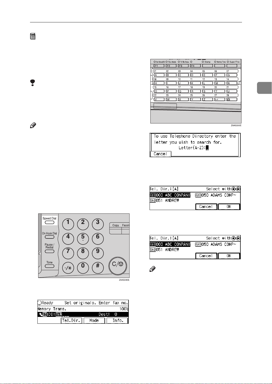
Number Keys
Preparation
To use the Telephone Directory
feature, you need to register a
search letter when you program
Speed Dials. ⇒ P.138
Speed Dials”
Limitation
❒ Speed Dial codes cannot be
searched for by symbol or number.
❒ Names enclosed within brackets
are not searched for.
Note
❒ If you store the Telephone Directo-
ry function in a User Function key
beforehand, you can bring up the
Telephone Directory screen with a
single key press. ⇒ P.161
SIGNING USER FUNCTION
KEYS”
“Registering
“AS-
A Set your original and select any
scan settings you require.
D Enter the search letter by pressing
one of the Quick Dial keys (A to
Z).
2
The names or fax numbers registered in Speed Dials are shown in
numerical order on the display.
B Press the
C Press
[
Tel.Dir.
{
Speed Dial
.
]
key.
}
E Press the 0 or 1 key to select the
destination then press
Note
❒ If the list does not contain the
desired destination, press
or
↑
[
Prev.
❒ If you make a mistake, press the
{
Clear/Stop
❒ If you wish to dial another des-
tination, press
other fax number.
F Press the
↓
]
[
key to try again.
}
{
Start
Next
[
key.
}
.
]
Add
]
.
[
]
OK
and dial an-
49
Page 64

2
Sending a Fax Message
Groups
If you frequently send the same message to more than one place, program
these numbers into a Group. Then
you can send the messages to all the
destinations in that Group with just a
few keystrokes. You can also program a name for the Group (for example, “Branch Offices”) which will be
displayed before you press the
key.
Preparation
You need to program the Groups.
⇒ P.130
Limitation
❒ A Quick Dial programmed with a
Group cannot be used for other
functions.
❒ Groups can only be used for Mem-
ory Transmission; they cannot be
used for Immediate Transmission.
“Registering Groups”
{
Start
❒ Groups can contain Transfer Sta-
tion codes, but note that these
Groups cannot be used for normal
transmission because the Transfer
Station codes are not dialable numbers. ⇒ P.178
“Multistep Transfer”
A Set your original and select any
scan settings you require.
B Specify the Group in one of the
}
following ways:
• Press the Quick Dial key in
which the Group is programmed.
❒ If you do not assign Groups to a
Quick Dial key, you need to have
stored the Group function in a
User Function key beforehand in
order to access them.
Note
❒ Groups are only available with
Memory Transmission.
❒ To check the contents of the
Groups, print the list.
❒ You can program up to 9 Groups .
❒ You can store up to 256 destina-
tions in a Group (up to 500 destinations with optional Fax Function
Upgrade Unit installed). If a Quick
Dial or Speed Dial is registered in
two Groups, it takes up the space
of one destination. If the total
number of dials exceeds 256 (up to
500 destinations with optional Fax
Function Upgrade Unit installed),
you cannot specify anymore.
50
• Press the User Function key
{
}—{F4}
F1
function, then enter the Group
number with the number keys.
Note
❒ To see which Groups have
been programmed, press
[
GpD List
User Function (
key. ⇒ P.161
USER FUNCTION KEYS”
The Group number is shown on
the display. If the Group Name is
programmed, the name is also
shown on the display.
assigned the Group
after you press the
]
}—{F4}
{
F1
“ASSIGNING
)
Page 65

Number Keys
Note
❒ If you make a mistake, press the
key and start again.
{
Start
}
key.
}
and dial an-
]
[
Add
{
Clear/Stop
❒ If you wish to dial another des-
tination, press
other fax number.
C Press the
Redial
The machine memorizes the last 10
destinations that have been dialed. If
you wish to send a message to a destination which you faxed to recently,
the Redial feature saves you finding
and entering the number again.
A Press the
{
Pause/Redial
key.
}
• Quick Dials
• Speed Dials
• Group Dials
• Destinations dialed by a Program
• Destinations dialed as End
Receivers for Transfer Request
• Forwarding terminal of the
substitute reception
• Destination of Memory File
Transfer
• Destinations dialed using the
external telephone keypad
• Destinations dialed by Redial (regarded as already memorized)
• Any destinations after the
first number if multiple destinations were dialed
2
B A list of previously dialed num-
bers will flash up. If you cannot
see the number you need use the
↑
[
through them. Then enter the
code for the number you wish to
redial e.g., “01”.
❒ The following kinds of destina-
and
]
Prev.
Limitation
tions are not memorized:
↓
[
keys to scroll
]
Next
❒ Do not dial any digits before
you press the
key. If you press the
key after entering digits us-
}
dial
ing the number keys, a pause
will be entered instead.
Note
❒ If the receiver uses a fax ma-
chine of the same manufacturer
that is capable of registering the
RTI, that name may be shown
on the display instead of the fax
number.
{
Pause/Redial
{
Pause/Re-
}
51
Page 66

2
Sending a Fax Message
TRANSMISSION FEATURES
❒ By default, Stamp is turned off. If
Stamp
ARDF is required.
When sending a fax message using
the Document Feeder (ARDF), the
machine can stamp a circle mark at
the bottom of the original. Double
sided documents are stamped on the
bottom of the front page and top of
the rear page. This indicates that the
original has been successfully stored
in memory for Memory Transmission, or that it has been successfully
sent for Immediate Transmission.
you use this feature often, you can
adjust the User Parameters so that
the home setting is on. In this case,
Stamp can easily be turned off for
any single transmission by pressing the
“Changing the User Parameters”
A Press the
The Stamp indicator will light.
Pressing the
will turn it off.
{
Stamp
{
Stamp
key. ⇒ P.206
}
key.
}
{
Stamp
key again
}
Limitation
❒ Stamp only works when scanning
from the Document Feeder (ARDF).
❒ You cannot turn the Stamp feature
on or off while a document is being
scanned.
❒ Do not open the document feeder
(ARDF) while scanning the document. Document jam should occur.
Note
❒ When the stamp starts getting
lighter, replace the cartridge. ⇒
P.221
CARTRIDGE”
“REPLACING THE STAMP
52
ID Transmission (Closed
Network)
This feature allows you to restrict
transmission of messages only to machines of the same make, and only to
those machines that have the same
Polling ID. The transmission options
let you switch ID transmission on and
off for each separate transmission.
Note
❒ The default setting is off. Turn this
feature on with the User Parameters. ⇒ P.206
Parameters”
“Changing the User
F Code (SUB)
Normally you can only use Confidential Transmission to send to fax machines of the same make that have the
Confidential Reception feature. However, if the other machine supports a
similar feature called “F Code”, you
can send fax messages to the other
party using this method instead.
Page 67

TRANSMISSION FEATURES
Preparation
You need to assign the F Code feature to a User Function key beforehand. ⇒ P.161
FUNCTION KEYS”
You can only use this feature with
G3 communications.
You cannot use Chain Dial with
this feature.
You cannot select this function
when carrying out standard Confidential Transmission
Note
❒ The ID can be up to 20 digits long
and consist of digits, spaces, * and
# .
❒ Make sure the ID matches the
specification of the fax you are
sending to.
❒ You can store IDs in Quick Dials,
Speed Dials, Groups and Programs.
❒ Messages you send using this fea-
ture are marked “SUB” on all reports.
“ASSIGNING USER
A Set your document and make any
changes to the scan settings if necessary.
D Enter the function number for
SUB(S) on the number keys.
E Enter the SUB code with the
number keys.
F Press the
Note
❒ If you use Immediate Transmis-
sion and the destination fax machine does not support the F
Code feature, a message will appear on the display to inform
you of this. In this case, press
[
OK
{
to cancel the transmission.
]
F Code (SID)
Start
key.
}
2
B Dial the destination fax number
using the number keys.
C Press the User Function key as-
signed with the F Code feature.
There are times when you may wish
to use a “SID” (Sender ID) when
sending confidential faxes with the F
Code “SUB” feature.
Limitation
❒ You can enter a SID up to 20 digits
long.
Note
❒ Messages you send using this fea-
ture are marked “SID” on all reports. ⇒ P.154
“REPORTS/LISTS”
53
Page 68

2
Sending a Fax Message
JBIG Transmission
The optional Fax Function Upgrade Unit
is required.
If you use JBIG (Joint Bi-level Image
Experts Group) compression you can
send photographic originals faster
than the other compression method.
Limitation
❒ This feature is not available in G4.
❒ If ECM is turned off, JBIG Trans-
mission is not available.
❒ This feature requires that the other
party's fax machine has both the
JBIG function and ECM function
(G3 communication only).
Note
❒ When the optional extra G3 Inter-
face Unit is installed, JBIG transmission from the optional extra G3
Interface Unit (G3-2) is available as
standard.
54
Page 69

3. Receiving a Fax Message
IMMEDIATE RECEPTION
Each page of a received fax message is
printed as soon as it is received. This
method is used for standard fax messages.
Receiver (your machine)
Sender
ND1X00E2
Display During Reception
-
The sender's RTI or CSI appears on
the first line.
Reception will not take place if there
is not enough free memory left. If free
memory reaches 0% during Immediate Reception, any further reception
becomes impossible and the current
communication is terminated.
Reception Resolution
-
This machine supports Standard, De-
tail, Fine (optional Expansion Memo-
ry required) and Super Fine (optional
Expansion Memory required) resolutions for reception. If you do not have
the optional Expansion Memory, faxes sent at Fine or Super Fine resolution will be printed on your machine
at Detail resolution. This may result
in a slightly different from the sender's intention.
55
Page 70

Receiving a Fax Message
MEMORY RECEPTION
3
The machine waits until all pages of
the message have been received into
memory before printing the message.
Receiver (your machine)
Sender
ND1X00E3
This method is used with the following features:
• Combine 2 originals ⇒ P.67
bine 2 originals”
• Multi-copy when set to multiple
copies ⇒ P.65
tion”
• Reverse Order Printing ⇒ P.68
“Reverse Order Printing”
• Substitute Reception ⇒ P.57
stitute Reception”
• 2-sided Printing (optional Duplex
Unit required) ⇒ P.65
Printing”
“Multi-copy Recep-
“Com-
“Sub-
“2-Sided
Limitation
❒ The machine may not be able to re-
ceive fax messages when the free
memory space is low.
Note
❒ If the memory free space reaches
0% during Memory Reception, the
machine can no longer receive the
current fax message and stops
communicating.
Important
❒ All the messages stored in memory
are deleted if the power is
switched off for about more than
one hour.
❒ The machine may not be able to re-
ceive large numbers of messages
or messages with a high data content. In such cases, we recommend
you switch the above features off
or add a memory card.
56
Page 71

Substitute Reception
Substitute Reception
If any of the conditions listed below
are met, the machine automatically
switches to Memory Reception mode
and stores messages in memory instead of printing them. This reception
mode, in which a received fax message is stored in memory unprinted,
is called Substitute Reception. Messages received using Substitute Reception are automatically printed
when the condition which caused the
machine to use Substitute Reception
is rectified. Substitute Reception takes
place when:
• Paper runs out
• Toner runs out
• Paper is jammed
• A cover is open
• A fax is received during a copy or
print run
Limitation
❒ Reception may not take place if
there is not enough free memory
left.
Note
❒ The Receive File indicator lights to
let you know when message(s)
have been received using Substitute Reception.
❒ If free memory reaches 0% during
Substitute Reception, any further
reception becomes impossible and
the current communication is terminated.
Screening Out Messages from
Anonymous Senders
ry, the machine can be programmed to
only use Substitute Reception under
the following conditions.
Four settings are available:
• “When RTI or CSI is received”
• “Free”
• “disable”
• “Polling ID”
Note
❒ The default setting is “When RTI
or CSI is received”, i.e. only store
messages when the RTI/CSI is
present. You can change this with
the User Parameters. ⇒ P.206
“Changing the User Parameters”
❒ Even if the sender does not have an
RTI or CSI, the machine will still
receive messages using Substitute
Reception if:
• Paper becomes jammed while
the power switch is on
• For some reason printing is not
possible e.g., copy job is in
progress
When RTI or CSI is Received
-
The machine switches to Substitute
Reception only when the sender has
programmed their RTI or CSI. If the
power is switched off for more than
an hour, all the messages received
into memory are deleted. In such a
case, the Power Failure Report or the
Journal can be used to identify which
messages are lost so you can ask the
senders to transmit them again.
3
To help you screen out unwanted messages that may fill up machine memo-
57
Page 72

3
Receiving a Fax Message
Important
❒ If a sender has not programmed
their RTI or CSI, the machine may
reject an important fax message.
We recommend that you ask important senders to register an RTI
or CSI in advance.
Free
-
The machine switches to Substitute
Reception regardless of whether or
not the sender has programmed their
RTI or CSI.
Polling ID
-
The machine switches to Substitute
Reception only when you have received a message with the same Polling ID of your machine.
58
Page 73

SELECTING THE RECEPTION MODE
SELECTING THE RECEPTION MODE
There are two ways you can set up
your machine to handle incoming
calls:
• Facsimile mode
• Telephone mode (external Telephone required)
The default setting is Facsimile mode.
You can change this with the Initial
Setup RX settings.⇒ P.158
SETUP RX”
Limitation
❒ When the optional extra G3 Inter-
face Unit is installed, the reception
mode is automatically set to facsimile mode and cannot be
changed.
“INITIAL
Receiving a Fax in Telephone
-
Mode
This feature needs a User Function
key programmed as Start Manual RX.
By default,
signed this function. ⇒ P.161
SIGNING USER FUNCTION KEYS”
A When the machine rings, pick up
the handset.
B If you hear beeps, press the User
Function key (
has been programmed as the Start
Manual RX key.
C Replace the handset. The machine
will start receiving.
key is already as-
}
{
F1
{
F1
}–{F4}
“AS-
3
) which
Facsimile Mode (Auto
Reception Mode)
When a telephone call comes in, the
machine receives it automatically as a
fax message. Use this setting for a
dedicated fax line.
Telephone Mode
When a call comes in, you have to
pick up the handset or external telephone and decide whether the call is
a fax message yourself. If you hear a
voice, continue your conversation as
you would using a normal telephone.
If you hear high pitched beeps, instruct the machine to receive the fax
by following the procedure below.
Use this setting if you wish to share
the line between the fax machine and
a telephone.
Changing from Facsimile
-
Mode to Telephone Mode
This function also requires the use of
a User Function key. By default,
key is assigned as the
To change the reception mode, press
the User Function key which has been
programmed as the Telephone Mode
key. ⇒ P.161
FUNCTION KEYS”
{
TEL Mode
“ASSIGNING USER
{
key.
}
F2
}
59
Page 74

Receiving a Fax Message
RECEPTION FUNCTIONS
3
Transfer Station
Transfer Stations allow you to expand
the standard features of your fax machine to set up complex networks.
Transfer Stations must be machines of
the same make.
The diagram below may make the
concept clearer.
Requesting
party
The following terminology is used in
this section.
❖
Requesting Party
The machine where the message
originates from, i.e. the machine
making a Transfer Request.
❖
Transfer Station
The machine that forwards the incoming message to another destination, i.e. the machine that
receives the Transfer Request. In
this section this refers to your machine.
❖
End Receiver
The final destination of the message, i.e. the machine that the
Transfer Station sends to. End Receivers must be programmed into
Quick Dials, Speed Dials or
Groups in the Transfer Station
(this machine).
60
Transfer station
Transfer
result report
End Receiver
End Receiver
End Receiver
ND1X00E4
Limitation
❒ Polling ID's of the Requesting Par-
ty and Transfer Station must be
identical for this feature to work.
❒ If the Transfer Report setting is not
programmed at the Transfer Station, reception will not take place.
❒ This machine will not receive a
Transfer Request unless it has
enough free memory to store two
or more destinations dialed from
the number keys.
❒ If the Requesting Party specifies a
Group for the End Receivers and
the total number of End Receivers
exceeds 300, (500 with optional Fax
Feature Expander installed) the
Transfer Station cannot transfer
the message and sends a Transfer
Result Report to the Requesting
Party.
Reference
P.93
“TRANSFER REQUEST”
Multistep Transfer
-
The principles of Transfer Stations
can be used to build up a multi-step
facsimile network where messages
are passed through several Transfer
Stations. By programming the end receivers in a Transfer Station Group,
you can enable this machine to transfer messages onto other Transfer Stations.
For more information, contact your
service representative.
This feature can only be used if the
machines are made by the same maker.
Reference
P.178
“Multistep Transfer”
Page 75

Sending the Transfer Result
-
Report
This machine compares the own fax
number of the Requesting Party with
the Requesting Party's number programmed in a Quick Dial or Speed
Dial, and if the lower five digits of the
two numbers match, it sends the
Transfer Result report to the Requesting Party.
For example:
• Requesting Party's own dial
number:
001813-11112222
• Transfer Station's Quick Dial:
RECEPTION FUNCTIONS
Note
❒ By default, a portion of the original
image is printed on this report.
You can turn this off with the User
Parameters. ⇒ P.206
User Parameters”
“Changing the
ID Reception (Cl osed Network)
If you wish to limit reception of messages to those from machines of the
same make and with the same Polling
ID, contact your service representative to turn this feature on.
F Code (SEP)
3
03-11112222
Transfer Result Report
This reports whether transmission to
the End Receivers was successful or
not.
Preparation
Register the own fax number in advance. ⇒ P.41
LINE TYPE”
When the Transfer Station has transferred the message to all End Receivers, it sends the Transfer Result
Report back to the Requesting Party.
The machine prints the report if it
cannot be sent back to the Requesting
Party. You must program the fax
number of the requesting party in a
Quick Dial or Speed Dial in the Transfer Station. ⇒ P.125
Dials”
, P.138
“CHANGING THE
“Registering Quick
“Registering Speed Dials”
Normally you can only use Polling
Reception to receive faxes from machines that have the Polling Reception feature of the same make.
However, if the other machine of another make supports a polling reception, you can receive fax messages
from the other party using this method instead.
Preparation
You need to assign the F Code feature to a User Function key beforehand. ⇒ P.161
Contents of a User Function Key”
Limitation
❒ You can only use this feature with
a G3 line (not with G4).
❒ You cannot use Chain Dial with
this feature.
Note
❒ The ID can be up to 20 digits long
and consist of digits.
❒ Make sure the ID matches the
specification of the fax you are
sending to.
“Storing/Editing the
61
Page 76

Receiving a Fax Message
3
❒ You can store IDs in Quick Dials,
Speed Dials, Groups and Programs with number keys, space, #
and *.
❒ Messages you receive using this
feature are marked “SEP” on all reports.
A Make sure that the machine is in
Facsimile mode and the standby
display is shown. Then enter the
fax number.
B Press the User Function key as-
signed with the F Code feature.
F Enter the function number for
“Polling RX” on the number keys.
Note
❒ If you can't see the function
number, search for it using the
↑
[
Prev.
and
]
↓
[
arrow keys.
]
Next
G Depending which method you
are using, choose one of the following procedures:
Default ID Polling Reception
C Enter the function number for
SEP(P) on the number keys.
D Enter the SEP code with the
number keys.
E Press
The Transmission Mode menu is
displayed.
[
Mode
.
]
A Press the 0 or 1 key to change
the Default ID and press
ID Override Polling Reception
A Press the 0 or 1 key to change
the Override ID and press
B Enter a polling ID (4 charac-
ters) with the number keys and
Quick Dial keys. The ID can
contain digits 0–9 and letters
A-F (0000 and FFFF are not
available).
[
OK
[
OK
]
.
.
]
62
Page 77
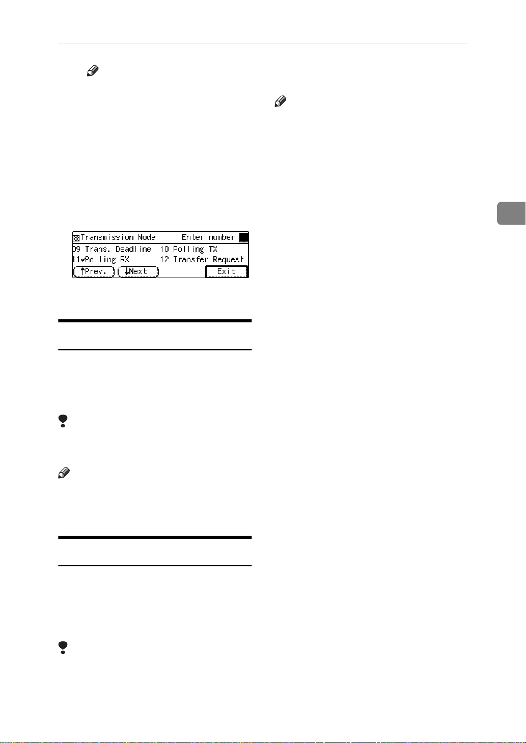
RECEPTION FUNCTIONS
Note
❒ If you make a mistake, press
the
{
Clear/Stop
again.
H Press
I Press
The display returns to the Transmission Mode menu and the Polling Reception function is now
checked.
J Press the
[
OK
[
Exit
.
]
]
{
.
Start
}
key and try
}
key.
F Code (PWD)
There are times when you may wish
to use a password when receiving
faxes by polling with the F Code
“SEP” feature. ⇒ P.61
“F Code (SEP)”
❒ This feature is not available with
G4 lines.
Note
❒ When the optional extra G3 Inter-
face Unit is installed, JBIG reception from the optional extra G3
Interface Unit (G3-2) is available as
standard.
3
Limitation
❒ You can enter a password up to 20
digits long.
Note
❒ Messages you send using this fea-
ture are marked "PWD" on all reports.
JBIG Reception
The optional Fax Function Upgrade Unit
is required.
It allows you to receive messages sent
in the JBIG format.
Limitation
❒ If ECM is turned off, JBIG Recep-
tion is not available.
63
Page 78

Receiving a Fax Message
PRINTING FUNCTIONS
3
Print Completion Beep
By default, the machine beeps to let
you know when a received message
has been printed.
Note
❒ You can alter the volume of the
beep or turn it off completely (set
the volume to the minimum level).
⇒ P.173
“Monitor Volume”
Checkered Mark
By default, a checkered mark is printed on the first page of fax messages to
help you separate them.
Centre Mark
By default, marks are printed halfway
down the left side and at the top centre of each page received. This makes
it easy for you to position a hole
puncher correctly when you file received messages.
ND1X00E6
Limitation
❒ The centre mark may deviate a lit-
tle from the exact centre of the
edge.
Note
❒ You can turn this feature off with
the Initial Setup RX settings. ⇒
P.158
“INITIAL SETUP RX”
64
ND1X00E5
Note
❒ You can turn this feature off with
the Initial Setup RX settings. ⇒
P.158
“INITIAL SETUP RX”
Reception Time
You can have the date and time when
a message was received printed at the
bottom of the received image. This
feature is turned off by default—turn
it on with the Initial Setup RX settings. ⇒ P.158
Limitation
❒ When a received message is print-
ed on two or more sheets, the date
and time is printed on the last
page.
“INITIAL SETUP RX”
Page 79
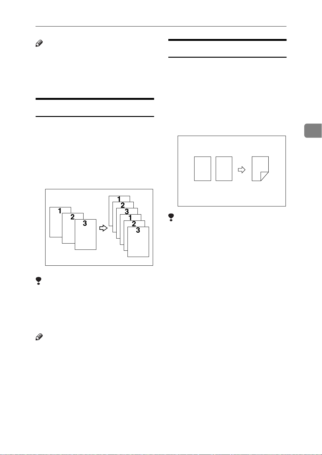
PRINTING FUNCTIONS
Note
❒ The date and time when the mes-
sage was printed can also be recorded on the message. If you need
this feature, please contact your
service representative.
Multi-copy Reception
If you switch this feature on, multiple
copies of each incoming fax message
will be printed. You can also choose
to have multiple copies made of messages from particular senders. ⇒
P.158
“INITIAL SETUP RX”
“Special Senders to Treat Differently
(Special RX Nos.)”
Limitation
❒ The maximum number of copies
that can be made of each message
is 10. If you are using Multi-copy
with Specified Senders, the maximum number is 10.
Note
❒ By default this feature is turned
off. Switch it on and set the
number of copies with the Initial
Setup RX settings. ⇒ P.158
TIAL SETUP RX”
❒ Note that the machine will use
Memory Reception for Multi-copy
Reception.
, P.180
ND1X00E7
“INI-
2-Sided Printing
The optional Duplex Unit is required.
With this option installed, you can
have a received message printed on
both sides of the paper. By default,
this feature is turned off. Switch it on
with the Initial Setup RX settings and
select lengthwise L copy paper. ⇒
P.158
❒ To use this function all pages of the
“INITIAL SETUP RX”
12
Limitation
1
2
received document must be of the
same size—inform the sending
party of this beforehand if necessary. You must also have paper set
in your machine of the same size as
that sent by the sending party
(A4→A4, B4→B4 are typical examples, whether A3 and B5 sizes are
scanned in correctly will depend
on the fax machine). This machine
will scan in correctly landscape
A3, B4, A4, B5 and portrait A4, B5
and A5. The table below shows the
results that can be achieved when
sending and receiving using this
machine.
3
65
Page 80

Receiving a Fax Message
3
❒
Originals
ABC
A
BA
4
.
B
5
BA
ABC ABC
A
3
.
B
4
❒ This feature works only when all
pages are of the same width and
are received into memory.
❒ Note that the machine will use
Memory Reception for 2-Sided
Printing.
❒ This feature cannot be used with
Combine 2 originals.
❒ Printouts may vary in their direc-
tion/orientation depending on
how the sender set them.
❒ If another party sends you a fax
and their machine is not able to detect the size of the original correctly, the message may come out
truncated, separated or containing
excess white space when printed at
your end. For example, if the sending machine thinks a B5 original is
a B4 original, it will be printed at
your end on B4 size paper even if
you have B5 paper available in
your machine.
BA
Top Binding
Side Binding
ND0X03E3
Note
❒ You can choose to have messages
only from selected senders printed
in this way. ⇒ P.180
ers to Treat Differently (Special RX
Nos.)”
“Special Send-
180 Degree Rotation Printing
When printing on both sides of the
paper, this machine rotates images as
shown in the diagram.
1
2
1
2
CP2B02E0
Image Rotation
If you have installed paper in the cassette sideways K, incoming fax messages will be rotated automatically to
fit on the paper.
your machine
ND1X00E9
Note
❒ You can choose to have received
messages printed from the specified tray. ⇒ P.214
tion”
“Paper Feed Selec-
66
Page 81

PRINTING FUNCTIONS
Combine 2 originals
When two messages of the same size
and direction are received consecutively, they are printed on a single
sheet when you turn this feature on.
This can help you economize on paper.
• Two A5K messages are printed
side by side on a sheet of A4L.
• Two B5K messages are printed
side by side on a sheet of B4L.
• Two A4K messages are printed
side by side on a sheet of A3L.
1
/
"×11"L.
2
1
• Two 8
printed side by side on a sheet of
8
12
1
/
"×5
/2"K messages are
2
12
Combine1
Note
❒ By default this feature is turned
off. Switch it on with the User Parameters. ⇒ P.206
User Parameters”
❒ This feature uses Memory Recep-
tion.
“Changing the
Page Separation and Length
Reduction (not availabl e in
some countries)
When the size of a received message
is longer than the paper loaded in the
machine, each page of the message
can be split and printed on several
sheets, or reduced and printed on a
single sheet. For example, this feature
splits the received message if the excess length is about 20mm or more,
and reduces it if the excess length is
within about 20mm. When a message
is split, the split mark (*) is inserted at
the split position and about 10mm of
the split area is duplicated on the top
of the second sheet.
3
Limitation
❒ This feature does not work with
messages larger than A5K, B5K,
A4K, or LTK. When A5K, B5K,
A4K or LTK size paper is loaded
in the machine, each page of the received message is output on a single sheet.
❒ If paper matching the size and di-
rection of a received document is
not available, Combine 2 originals
is not possible.
❒ When "Combine 2 originals" and
"2-Sided Printing" are selected at
the same time, combine 2 originals
takes priority and 2–sided printing
is canceled.
ABC
(Document)
ND1X01E1
Note
❒ Your service representative can
customize this feature with the following settings. Bracketed values
are defaults.
•Reduction (on)
• Print split mark (on)
67
Page 82

3
Receiving a Fax Message
• Overprinting (on)
• Overprinting length (10mm)
• Guideline for split (when message is 20mm longer than paper)
❒ You can adjust the overprinting
length and length of reduction
within the following ranges:
• Guideline for split: 5∼155mm
(5mm steps)
• Overprinting length: 4mm,
10mm, 15mm
Reverse Order Printing
Page Reduction
If you have switched this feature on
and you receive a message that is
longer than the paper in the cassette,
usually the machine prints it on two
pages. If you turn this feature on the
machine reduces the width and
length of the received image so that it
will fit on one page. If A4L paper
size is loaded and a message of B4L
size is received, the machine will reduce the message to a single A4L
sheet.
Normally, received pages are printed
and stacked on the tray in the order
they are received. If you turn this feature on, the machine will start printing the message from the last page
received.
your machine
Note
❒ By default, this feature is turned
off. Switch it on with the Initial Setup RX settings. ⇒ P.158
SETUP RX”
❒ When this feature is on, the first
page will be printed last.
❒ This feature uses Memory Recep-
tion.
68
Print
ND1X01E2
“INITIAL
your machine
(B4 size)
Note
reduction
(A4 size)
ND1X01E3
❒ By default this feature is turned
off. Switch it on with the User Parameters. ⇒ P.206
“Changing the
User Parameters”
Reference
P.67
“Page Separation and Length Reduction (not available in some countries)”
TSI Print
Usually the sender's TTI is printed on
received messages. If the sender has
not programmed their TTI, you will
not be able to identify them. However, if you turn this feature on, the
sender's RTI or CSI is printed instead
so you can find out where the message came from. ⇒ P.169
⇒ P.200
“G3 Analog Line”
“RTI/TTI”
Page 83

PRINTING FUNCTIONS
Note
❒ You can turn it on or off with the
User Parameters. ⇒ P.206
ing the User Parameters”
“Chang-
CIL/TID Print
The optional ISDN Unit is required.
Two features are provided for identification of messages received by G4
(ISDN). If turned on, this information
will be printed on every page.
The CIL (Call Identification Line) refers to the combination of the receiver's own fax number, name, the
sender's own fax number and name,
time, and page number. The default
setting is on. The TID refers to the
name registered by the sender in their
TTI. The default setting is off.
Limitation
❒ These features are available only
when receiving in G4 mode.
❒ If the sender's TID contains dou-
ble-byte characters (e.g. Chinese
characters), the TID will not be
printed even if TID Print is turned
on.
Note
❒ You can turn CIL and TID on or off
with the User Parameters. ⇒ P.206
“Changing the User Parameters”
When There is No Paper of the Correct Size
If there is no paper in your machine that matches the size of a received message,
the machine will choose a paper size based upon the paper you have available.
For example, if your machine has B4L and A5K installed and you receive an
A4L size message, check the A4 column of the table below. The paper size at
the top has the highest priority. In this case, since B4L is higher priority than
A5K, the message is printed on B4L.
If only B5L is loaded and you receive an A3L message, the received message
is stored in memory and will not be printed.
3
69
Page 84

3
Receiving a Fax Message
❖
Priority Table
Page Reduction Disabled
Reduction in Sub-scan Direction Enabled
Page Separation Threshold 20mm
Width or Length Priority Width
70
Page 85

PRINTING FUNCTIONS
• KK and LL indicate that the message is split over two pages of paper with
the orientation and size shown.
Limitation
❒ Paper placed in the bypass tray is not usually selected for printing a received
message. However, you can use this tray if you select the bypass tray as the
main paper tray using Reception with Specified Senders. ⇒ P.180
“Special
Senders to Treat Differently (Special RX Nos.)”
❒ The paper size used to print a received message may be different from the size
of the sent original.
Note
❒ Widths that this machine can receive are A4, B4, LT, LG, and A3. Any mes-
sages narrower than A4 or LT are sent as A4 or LT width with the length unchanged.
Reference
P.67
“Page Separation and Length Reduction (not available in some countries)”
P.68
“Page Reduction”
P.66
“Image Rotation”
”Just Size” Printing
If you turn this feature on and no paper tray is stocked with paper of a suitable
size to print a received document, a message will appear on the display prompting you to load paper of the required size. When you have loaded the new paper,
you can then print the message.
Two messages can appear:
• Paper Cassette
Paper designated to print FAX/Lists are
empty.
Refill A4 paper.
OK
ND0X04E0
3
• Bypass Tray
Paper designated to print FAX/Lists are
empty.
Refill A4 paper to Bypass tray.
OK
ND0X01E6
Note
❒ By default this message is turned off. You can turn this message on with the
User Parameters. ⇒ P.206
“Changing the User Parameters”
71
Page 86

3
Receiving a Fax Message
Out of Paper Display Message
If the paper tray runs out of paper, you can have a message appear on the display asking you to add more paper.
Note
❒ By default this message is turned off. You can turn it on with the User Param-
eters. ⇒ P.206
“Changing the User Parameters”
Having Incoming Messages Printed on Paper From the Bypass
Tray
You can have messages sent from Specified Senders printed on paper from the
Bypass Tray. This is useful if you need messages printed on a size of paper not
stocked in the paper cassette(s).
Limitation
❒ When the optional Fax Expansion Memory is installed, you can set paper be-
tween 148 and 1,200mm long in the Bypass Tray.
Note
❒ Before you can use this feature, you need to turn on Authorized Reception
(Initial Setup RX settings), program the Specified Senders (Key Operator Settings) along with the Paper Tray set to “Bypass Tray”. ⇒ P.158
UP RX”
❒ When you set paper sizes other than A4 landscape, B4 landscape and portrait,
A3 landscape and portrait in the Bypass Tray, specify the paper size. This size
should match the bypass paper size for copying or a paper jam may occur. To
change the bypass paper size for copying, see the chapter titled "COPY FROM
THE BYPASS TRAY" in the copy reference manual. ⇒ P.160
Paper Size”
❒ If the specified paper size and the size of paper set in the Bypass Tray do not
match, paper jams may occur and the image may be truncated.
❒ If you use this feature, Image Rotation is not possible.
, P.180
“Special Senders to Treat Differently (Special RX Nos.)”
“INITIAL SET-
“To Set the Bypass
72
Page 87

4. Advanced Transmission
OVERVIEW
Overview
This feature describes various options
that you can choose when sending a
fax message. The selections you make
will only apply to the current fax message.
Features
73
Page 88

Advanced Transmission Features
SEND LATER
4
Using this feature, you can instruct
the machine to delay transmission of
your fax message until a later time
which you specify. This allows you to
take advantage of off-peak telephone
charges without having to be by the
machine at the time.
Transmitter
Receiver
Send Later
at 21:00 (9:00PM)
ND1X01E4
For ease of use, you can program the
time when your phone charges become cheaper as the Economy Transmission time. ⇒ P.175
Economy Transmission Time”
Then if you have a non urgent fax,
just select Send Later with Economy
Transmission when you scan it in.
Faxes will be queued in memory and
will start being sent at Economy
Transmission time.
Note
❒ You can not specify a time more
than 24 hours into the future.
❒ If you wish to use Economy Trans-
mission, program the time when
your phone charges get cheaper. ⇒
P.175
Transmission Time”
❒ This feature is only available with
Memory Transmission.
“Registering the Economy
“Registering the
A Set your original and select any
scan settings you require.
B Press
The Transmission Mode menu appears.
[
Mode
.
]
C Enter the “Send Later” function
number with number keys.
D Enter the time with the number
keys. To change AM/PM, press
←→
[
AM
or press
Note
❒ If the current time shown on the
display is not correct, adjust it.
⇒ P.205
❒ When entering numbers small-
er than 10, add a leading zero.
❒ If you make a mistake, press the
{
Clear/Stop
❒ To cancel Send Later, press
[
Cancel
turn to the Transmission Mode
menu.
E Press
The Transmission Mode menu is
shown on the display. A check
mark is added to “Send Later”.
(North America only)
]
PM
[
Economy TX
“Date/Time”
key and try again.
}
and the display will re-
]
.
]
[
OK
.
]
74
Page 89

SEND LATER
F Press
The initial display is shown.
Note
❒ “Send Later” is shown on the
display. If you set up another
advanced transmission function
(except Polling Reception),
“Others” is displayed.
G Dial and press the
Note
❒ You can cancel transmission of
a message set up for Send Later.
⇒ P.101
sion”
[
Exit
.
]
key.
}
{
Start
“Canceling a Transmis-
4
75
Page 90

Advanced Transmission Features
CONFIDENTIAL TRANSMISSION
4
If you do not want your message to be
picked up casually at the other end,
use this feature. The message will be
stored in memory at the other end
and will not be printed until an ID is
entered.
Transmitter
Receiver
ND1X01E5
There are two types of Confidential
Transmission:
❖
Default ID
The other party can print the message by entering the Confidential
ID programmed in their machine.
Note
❒ We recommend that you program
the Confidential ID beforehand.
❒ An ID can be any 4 digit number
except 0000.
A Set your original and select any
scan settings you require.
B Press
The Transmission Mode menu appears.
[
Mode
.
]
C Enter the “Confidential TX” func-
tion number with the number
keys.
❖
ID Override
Should you wish to send a confidential message to a particular person at the other end, you can
specify the Confidential ID that
person has to enter to see that message. Before you send the message,
don't forget to tell the intended receiver the ID that must be entered
to print it.
Limitation
❒ The destination machine must be
of the same make and have the
Confidential Reception feature.
❒ The destination machine must
have enough memory available.
76
D Depending on the Confidential
Transmission type, use one of the
following procedures:
Default ID
A Press the 0 or 1 key to turn
Default ID on and press
The Transmission Mode menu
is shown again. A check mark is
added to “Confidential TX”.
[
OK
.
]
Page 91

CONFIDENTIAL TRANSMISSION
Note
❒ To cancel the Confidential
Transmission, press
The Transmission Mode
menu is shown on the display.
[
Cancel
Override ID
A Press the 0 or 1 key to turn
Override ID on.
B Enter the Confidential ID (4
digit number) with the number
keys and press
[
OK
.
]
Note
❒ “Conf.Trans” is shown on the
.
]
display. If you set up another
advanced transmission function
(except Polling Reception),
“Others” is displayed.
F Dial and press the
Note
❒ For details on deleting a Confi-
dential Transmission⇒ P.76
“CONFIDENTIAL TRANSMISSION”
{
Start
key.
}
4
The Transmission Mode menu
is shown again. A check mark is
added to Confidential TX.
Note
❒ To Cancel the Confidential
Transmission, press
The Transmission Mode
menu is shown on the display.
E Press
The initial display is shown.
[
Exit
.
]
[
Cancel
.
]
77
Page 92

Advanced Transmission Features
PERSONAL CODE TRANSMISSION
4
Personal Codes allow you to keep
track of machine usage (e.g., for billing purposes). If everybody uses a
Personal Code when they use the fax
machine, the codes or the names programmed for the codes will be printed in the Journal and other reports.
This will help you to check up on who
has been using the machine and how
often. ⇒ P.113
JOURNAL”
Limitation
❒ Personal codes may be any 8 digit
number except 00000000 (00000001
through 99999999). You can program up to 20 personal codes (50
personal codes with optional Fax
Function Upgrade Unit installed).
⇒ P.164
Codes”
“PRINTING THE
“Registering Personal
A Set your original and select any
scan settings you require.
B Press
[
Mode
.
]
D Enter a personal code (8 digit
number) with the number keys.
Note
❒ If a personal code is pro-
grammed with a name, it is
shown below the personal code
on the display.
❒ If you make a mistake, press the
key and try again.
{
Clear/Stop
❒ To cancel Personal Code Trans-
mission, press
Transmission Mode menu is
shown on the display.
E Press
The Transmission Mode menu is
shown again. A check mark is added to “Personal Code”.
F Press
[
OK
[
Exit
}
. The
[
Cancel
.
]
.
]
]
The Transmission Mode menu appears.
C Enter the “Personal Code” func-
tion number with the number
keys.
78
The initial display is shown.
Note
❒ Personal Code number is shown
on the display. If you set up another advanced transmission
function (except Polling Reception), “Others” is displayed.
G Dial and press the
{
Start
key.
}
Page 93

SENDING AN AUTO DOCUMENT
SENDING AN AUTO DOCUMENT
If you often have to send a particular
page to people (e.g. a map, a standard
attachment or a set of instructions),
store it as an Auto Document assigned to a Quick Dial key. Then,
when you need to send that page to
somebody, just press the Quick Dial
key that you assigned it to instead of
having to scan the whole page in
again.
Preparation
You need to program an Auto Document.
You can fax an Auto Document by itself, or attach it to a normal fax message.
Important
❒ Whenever you store or change an
Auto Document, we recommend
that you print the Auto Document
list for reference. ⇒ P.148
Document list”
Limitation
❒ You can attach one Auto Docu-
ment to each transmission.
❒ You can store up to 6 Auto Docu-
ments (up to 18 with optional Fax
Function Upgrade Unit installed).
⇒ P.146
ment”
Note
❒ Originals with Auto Documents
are sent by Memory Transmission.
❒ When sending an Auto Document
with another original, the Auto
Document is sent first.
❒ Storing Auto Documents reduces
the amount of free memory slightly. Unless you delete the document, free memory will not return
to 100%.
“Registering an Auto Docu-
“Auto
❒ You can print an Auto Document
or a summary of Auto Documents
currently stored in memory. ⇒
P.154
“REPORTS/LISTS”
A Set your original and select any
scan settings you require.
B Press
The Transmission Mode menu appears.
[
Mode
.
]
C Enter the “Auto Document” func-
tion number with the number
keys.
D Enter the number of the “Auto
Document” you want to send
with the number keys then press
.
]
[
OK
Note
❒ If the list does not contain the
Auto Document you want to
send, press
❒ If you make a mistake, press the
{
Clear/Stop
❒ To cancel the Auto Document,
press
sion Mode menu is shown.
↑
[
key and try again.
}
[
Cancel
or
↓
]
Prev.
. The Transmis-
]
[
Next
.
]
4
79
Page 94

Advanced Transmission Features
E If you are sending just the Auto
Document, press
to send it along with another original, press
The Transmission Mode menu is
redisplayed. A check mark is added to “Auto Document”.
[
OK
.
]
. If you wish
[#]
4
F Press
The initial display is shown.
Note
❒ “Auto Doc.” is shown on the
display. If you set up another
advanced transmission function
(except Polling Reception),
“Others” is displayed.
G Dial and press the
[
Exit
.
]
key.
}
{
Start
80
Page 95

2-SIDED TRANSMISSION (DOUBLE-SIDED TRANSMISSION)
2-SIDED TRANSMISSION (DOUBLE-SIDED
TRANSMISSION)
Use this feature to send 2-sided originals from the Document Feeder (ARDF). Both sides of an original will be
scanned. The front and back of the
scanned original will be printed in order on separate sheets at the other
end. Note that the orientation of alternate sheets may be reversed at the
other end.
Limitation
❒ The front and back of a 2-sided
document are scanned in different
directions. This means that when
the front and back sheets of each
page are printed at the other end,
they may be upside-down in relation to each other.
❖
Sending with Image Rotation
Note
❒ If the first page is a single-sided
cover sheet, you can choose to
have this page sent using singlesided transmission. The remaining
pages will be sent with 2–sided
Transmission feature.
❒ You can confirm whether both
sides were properly scanned in
with the Stamp feature. ⇒ P.52
“Stamp”
4
A Set your original in the Document
Feeder (ARDF) and select any
scan settings you require.
B Press
The Transmission Mode menu appears.
[
Mode
.
]
81
Page 96

Advanced Transmission Features
4
C Enter the “2-Sided Trans.” func-
tion number with the number
keys.
Note
❒ If the appropriate display is not
shown, press
↑
[
Prev.
or
]
[
↓
Next
D Press the 0 or 1 key to select the
first page that you want to be
scanned on both sides.
Note
❒ If your document contains a sin-
gle-sided cover letter as the first
page, select “From 2nd sheet”
so that the machine scans both
sides from the second page.
.
]
G Press
The initial display is shown.
❒ “2-Sided TX” is shown on the
The Transmission Mode menu is
redisplayed. A check mark is added to “2-Sided Trans.”.
[
Note
display. If you set up another
advanced transmission function
(except Polling Reception),
“Others” is displayed.
H Dial and press the
Exit
.
]
key.
}
{
Start
82
E Press
“Top to Top” and “Top to Bottom” (see the second display line
on the right).
F Press
S
[
[
OK
Orient.
]
to toggle between
]
.
Page 97

BOOK FAX
BOOK FAX
Use to send book originals from the
exposure glass. Pages are scanned in
the order shown below.
Note that depending on the paper sizes available on the destination machine, the message may be reduced
when printed at the other end.
Exposure glass
Note
❒ You can have bound originals
scanned in left page first or right
page first. By default, the machine
scans in the left page first but you
can change this setting with the
User Parameters. ⇒ P.206
ing the User Parameters”
THYS980E
“Chang-
Note
❒ If the appropriate display is not
shown, press
↑
[
Prev.
]
or
[
↓
Next
D Press the 0 or 1 key to select the
size of the original.
Note
❒ To cancel this mode, press
. The Transmission Mode
]
cel
menu is shown on the display.
❒ If you choose 11"×17", the origi-
nal will be sent using Image Rotation Transmission.
E Press
pages 1 and 2 (see the second display line on the right).
S
[
Pages
to toggle between
]
[
Can-
.
]
4
A Set your original on the exposure
glass and select any scan settings
you require.
B Press
The Transmission Mode menu appears.
[
Mode
.
]
C Enter the “Book Fax” function
number with the number keys.
Note
❒ Select “From Page 1” to send a
book original from the first
page.
❒ Select “From Page 2” if you
want to send a cover letter as the
first page.
F Press
The Transmission Mode menu is
shown. A check mark is added to
“Book Fax”.
[
OK
.
]
83
Page 98

Advanced Transmission Features
4
G Press
The initial display is shown.
Note
❒ “Book Fax” is shown on the dis-
play. If you set up another advanced transmission function
(except Polling Reception),
“Others” is displayed.
H Dial and press the
[
Exit
.
]
key.
}
{
Start
84
Page 99

CHOOSING THE AREA TO BE SCANNED YOURSELF (IRREGULAR SCAN AREA)
CHOOSING THE AREA TO BE SCANNED
YOURSELF (IRREGULAR SCAN AREA)
Usually the machine automatically
detects the size of an original when it
is scanned. However, you may wish
to override this and choose the area to
be scanned yourself.
You can either choose one of the
standard paper sizes (A4KL, B4L,
A3L, 8
one of two custom sizes programmed
in advance (Area 1 and Area 2). ⇒
P.16
Although you can specify a different
scan area for each page when using
the exposure glass, only one size is allowed when scanning from the Document Feeder (ARDF).
1
/
× 11"KL, 11" × 17"K) or
2
“Paper Size and Scanned Area”
A Set your original and select any
scan settings you require.
B Press
[
Mode
.
]
C Enter the “Irreg. Scan Area” func-
tion number with the number
keys.
Note
❒ If the appropriate display is not
shown, press
↑
[
Prev.
]
or
[
↓
Next
D Press the 0or 1 key to select the
paper size.
Note
❒ To see which paper sizes have
already been programmed,
press
[
Status
❒ To cancel the Irreg. Scan Area,
press
[
Cancel
E Press
Mode menu is shown. A check
mark is added to “Irreg. Scan Area”.
[
OK
.
]
.
]
. The Transmission
]
4
.
]
The Transmission Mode menu appears.
F Press
The initial display is shown.
[
Exit
.
]
85
Page 100

Advanced Transmission Features
Note
❒ “Irreg.Area” is shown on the
display. If you set up another
advanced transmission function
(except Polling Reception),
“Others” is displayed.
4
G Dial and press the
{
Start
key.
}
86
 Loading...