

Page 1

ISDN Unit
(Machine Code: A895)
September 20th, 1999
Subject to change
Page 2

TABLE OF CONTENTS
1. INSTALLA T ION.....................................................................A895-1
1.1 INSTALLATION PROCEDURE ..........................................................A895-1
1.2 USER LEVEL PROGRAMMING......................................................... A895-4
1.3 SERVICE LEVEL PROGRAMMING...................................................A895-5
2. SERVICE TABLES AND PROCEDURES .............................A895-6
2.1 SERVICE LEVEL FUNCTIONS..........................................................A895-6
2.2 BIT SWITCHES..................................................................................A895-7
2.2.1 G4 INTERNAL SWITCHES........................................................A895-7
2.2.2 G4 PARAMETER SWITCHES.................................................A895-15
2.3 DEDICATED TRANSMISSION PARAMETERS...............................A895-20
3. TROUBLESHOOTIN G.........................................................A895-21
3.1 ERROR CODES...............................................................................A895-21
3.1.1 D-CHANNEL LAYER MANAGEMENT.....................................A895-22
3.1.2 D-CHANNEL, LAYER 1...........................................................A895-22
3.1.3 D-CHANNEL LINK LAYER......................................................A895-22
3.1.4 D-CHANNEL NETWORK LAYER............................................A895-23
3.1.5 B-CHANNEL LINK LAYER.......................................................A895-23
3.1.6 B-CHANNEL NETWORK LAYER............................................A895-24
3.1.7 TRANSPORT LAYER..............................................................A895-24
3.1.8 SESSION LAYER.................................................................... A895-25
3.1.9 DOCUMENT LAYER ...............................................................A895-26
3.1.10 PRESENTATION LAYER......................................................A895-26
3.2 G4CCU STATUS CODES ................................................................A895-27
3.2.1 LAYER 1 (PHYSICAL LAYER)................................................A895-27
3.2.2 LAYER 2 (LINK LAYER)..........................................................A895-27
3.2.3 NETWORK LAYER (LAYER 3)................................................A895-28
3.2.4 TRANSPORT LAYER (LAYER 4)............................................A895-28
3.2.5 SESSION LAYER, SESSION CONTROL LAYER (LAYER 5).A895-28
3.2.6 SESSION LAYER, DOCUMENT CONTROL
LAYER (LAYER 5)................................................................... A895-28
3.3 LEDS................................................................................................A895-29
3.4 BACK-TO-BACK TEST.....................................................................A895-30
i
Page 3
20 September 1999 INSTALLATION PROCEDURE
1. INSTALLATION
1.1 INSTALLATION PROCEDURE
ø
CAUTION
Before installing this option, do the following:
1. Print out all messages stored in the memory, the lists of userprogrammed items, and the system parameter list.
2. If there is a printer option in the machine, print out all data in the printer
buffer.
3. Turn off the main switch and disconnect the power cord, the telephone
line, and the LAN cable.
[B]
[C]
[D]
[A]
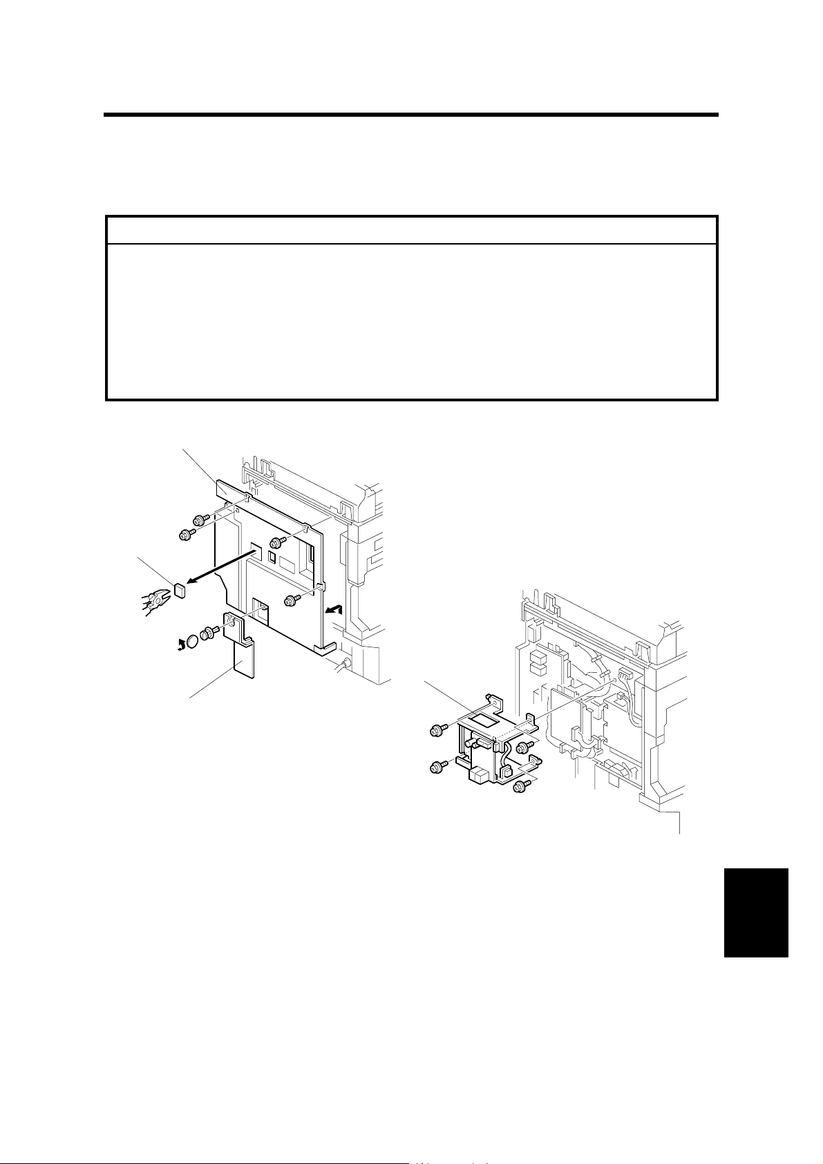
1. Remove the small cover [A] (1 rivet) and the rear cover [B] (4 screws). Then cut
away the jack window [C].
2. Remove the NCU unit [D] (4 screws, 2 connectors)
A895I310.WMF
A895I352.WMF
Options
A895-1
Page 4
INSTALLATION PROCEDURE 20 September 1999
[B]
[A]
A895I353.WMF
[A]
[E]
[C]
A895I311.WMF
[D]
[B]
A895I392.WMF
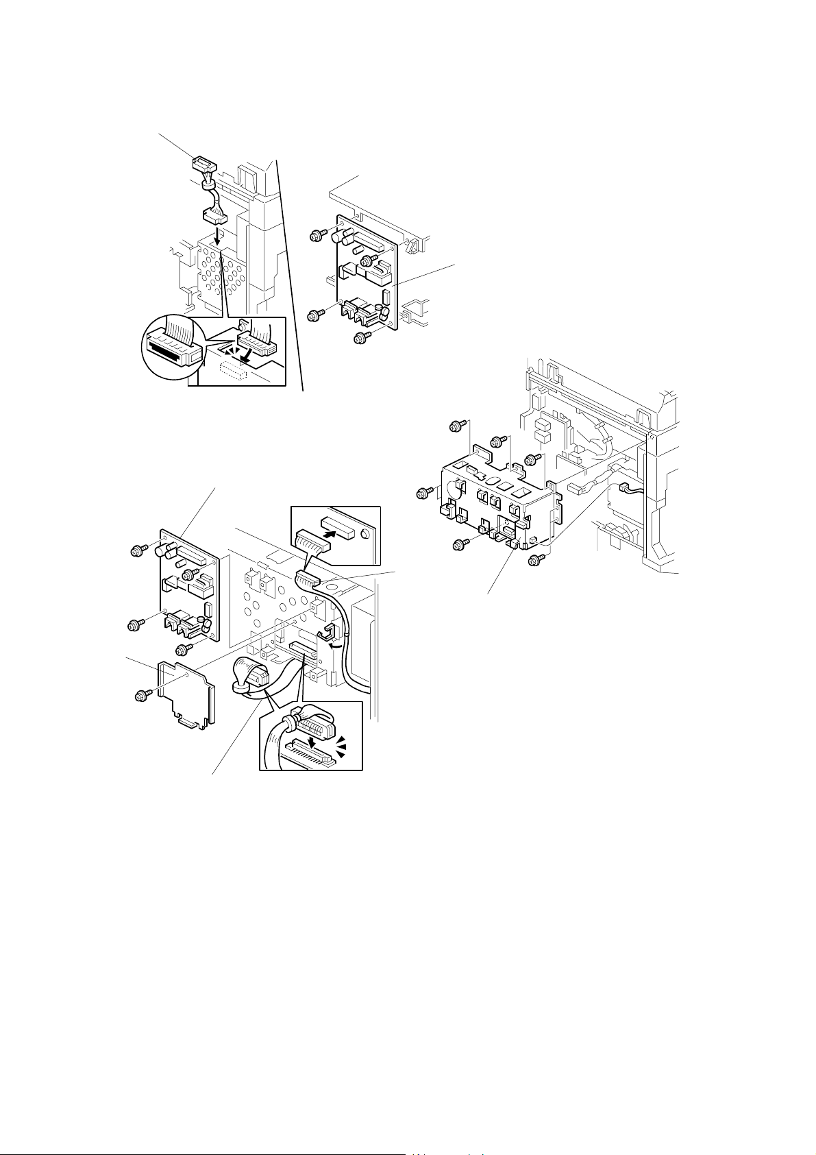
3. Remove the NCU [A] from the NCU unit (4 screws). Connect the harness [B] to
the FCU (CN604).
4. Attach the G4 unit [C] to the machine (6 screws, 1 connector).
5. Connect the harness [B] to the interface board and attach bracket [D] (1 screw).
Then attach the NCU [A] (removed from the NCU unit in step 3) to the G4 unit
(4 screws). After that, connect the harness [E] to the NCU [A], then clamp
harness [E] as shown.
A895-2
Page 5

20 September 1999 INSTALLATION PROCEDURE
6. Replace the rear cover and the small cover.
7. Connect the cable to the ISDN jack, then plug in the machine and turn the main
switch on.
8. Enter SP mode as follows:
1) Press the “Clear Modes” key.
2) Enter “107”
3) Press the “Clear/Stop” key more than 3 seconds.
T
9. Enter “2” (select “Fax”).
10. Enter “01” (select “Bit Switches”).
11. Enter “4” (select “Communication Switch”).
12. Press the “↑ Switch” key several time and select “Switch 16”.
13. Press “2” to change bit 2 from 0 to 1.
14. Exit SP mode and turn the main switch off/on.
→
ò
→
ó
→
ì
→
E
A895-3
Options
Page 6

USER LEVEL PROGRAMMING 20 September 1999
1.2 USER LEVEL PROGRAMMING
The following items can be programmed by the key operator. Make sure that the
items are programmed correctly.
Item
Transfer report:
G3 direct number
Transfer report:
G4 fax number
G3-1 analog line:
CSI
G3-2 analog line:
CSI
G3 digital line:
Own fax number1
G3 digital line:
Own fax number2
G3 digital line:
Sub-address
G3 digital line:
CSI
G4 digital line:
Own fax number1
G4 digital line:
Own fax number2
G4 digital line:
Sub-address
G4 digital line:
TID (Terminal ID)
ISDN PSTN
G4 G3 G3
é
éé
é
é
é
é
é
é
é
é
é
✔
Remarks
Used for transfer request operations in
G3 PSTN communications
Used for transfer request operations in
ISDN communications
Used to identify the terminal in G3
DIS/DCS communications over the
PSTN1.
Used to identify the terminal in G3
DIS/DCS communications over the
PSTN2.
When not using MSN* service:
Program the ISDN subscriber number
here. If an another terminal is on the
same bus from the DSU, identify the
terminals using a sub-address.
When using MSN* service:
Program the dedicated ISDN number
for the terminal as the 1st ISDN
subscriber number. If the customer
wishes the machine to answer calls to
two different numbers, program the
second number as the 2nd subscriber
no.
Program a sub-address to identify the
terminal, if two or more terminals
answer the call to the same subscriber
number for G3 fax.
Used to identify the terminal in G3
communications over an ISDN.
When not using MSN* service:
Program the ISDN subscriber number
here. If an another terminal is on the
same bus from the DSU, identify the
terminals using a sub-address.
When using MSN* service:
Program the dedicated ISDN number
for the terminal as the 1st ISDN
subscriber number. If the customer
wishes the machine to answer the
calls to two different numbers,
program the second number as the
2nd subscriber no.
Program a sub-address to identify the
terminal, if two or more terminals
answer the call to the same subscriber
number for G4 fax.
Used to identify the terminal in G4
communications.
A895-4
Page 7

20 September 1999 SERVICE LEVEL PROGRAMMING
Item
Polling ID
Confidential ID
Memory Lock ID
RTI (PSTN1/PSTN2)
TTI (PSTN1/PSTN2)
ISDN PSTN
G4 G3 G3
✔✔✔
✔✔✔
✔✔✔
✔✔
✔✔
Remarks
Used for secured polling, transfer
request operations, and closed
network.
Used for confidential reception.
Optional SAF memory required.
Used to identify the terminal in G3
NSF/NSS communications.
Printed on each transmitted page in
G3 communications.
* MSN = Multiple Subscriber Number; this is also referred to a s “Direct Dialing In”
in some countries. In this service, more than one number is allocated to one line
(one line can have up to 8 units connected to it).
1.3 SERVICE LEVEL PROGRAMMING
Item Function No. Remarks
System switches 01 - 1
Communication switches 01 - 4
G4 internal switches 01 - 6
G4 parameter switches 01 - 7
System Switch 0A
- Network used for G3 transmission
- Network used for G4-to-G3 fallback
Communication Switch 07
- G4-to-G3 fallback On/Off
- Reflect line type for G4-to-G3 fallback
Change the country code, and reset the
machine first. Then change any of the locally
required settings and/or the following.
Internal Switches 17, 18, 1A, 1B and 1C
- G4 to G3 automatic fallback parameters
Parameter Switch 01, bits 4 to 6
- Codec attenuation level
After changing any setting, make sure to turn off the machine, wait for 5 or more
seconds, then turn it back on, so that the new settings take effect.
A895-5
Options
Page 8

SERVICE LEVEL FUNCTIONS 20 September 1999
2. SERVICE TABLES AND PROCEDURES
2.1 SERVICE LEVEL FUNCTIONS
Refer to the Fax Unit service manual for how to operate the functions.
Enter SP mode as follows:
1) Press the “Clear Modes” key.
2) Enter “107”
3) Press the “Clear/Stop” key more than 3 seconds.
T
4) Enter “2” (select “Fax”).
Function Number Description
01 Programming G4 Internal and Parameter Switches
02 Printing System Parameter List
05 G4 Protocol Dump Lists
06 G4 RAM read/write and printing G4 Memory Dump List
11 ISDN G3 CCU tests
→
ò
→ ó → ì →
E
A895-6
Page 9

20 September 1999 BIT SWITCHES
2.2 BIT SWITCHES
õ
WARNING
Do not adjust a bit switch or use a setting that is described as "Not used",
as this may cause the machine to malfunction or to operate in a manner
that is not accepted by local regulations. Such bits are for use only in other
areas, such as Japan.
NOTE:
After changing any of the switches below, turn off the machine, wait for 5
seconds or more, and turn it back on, so that the new settings take effect.
2.2.1 G4 INTERNAL SWITCHES
Bit Switch 00
No. FUNCTION COMMENTS
0
Country code
to
7
Bit43210Country
00000France
00001Germany (1TR6 mode)
00010Universal (Europe Euro ISDN)
10001USA
Note: In Germany, use the UK setting for the Euro ISDN lines.
Bit switches 01 and 02 are not used.
Bit Switch 03
No. FUNCTION COMMENTS
0
1-7
Amount of protocol dump
data in one protocol dump
list
0: Last communication only
1: Up to the limit of the
memory area for protocol
dumping
Not used Do not change the factory settings.
Change this bit to 0 if you want to have a protocol
dump list of the last communication only.
This bit is only effective for the dump list #2 (D +
Bch1).
A895-7
Options
Page 10

BIT SWITCHES 20 September 1999
Bit Switch 04
No. FUNCTION COMMENTS
0-4
6-7
Bit Switch 05
No. FUNCTION COMMENTS
3-7
Not used Do not change the factory settings.
5 RCBCTR
0: Not valid 1: Valid
Not used Do not change the factory settings.
0
Not used Do not change the factory setting.
1
Logical channel number
(LCN)
0: Not controlled
1: Fixed at 01
2 Protocol ID check
0: Yes 1: No
Not used Do not change the factory settings.
This bit is used in Germany; set it to 1 for German
PTT approval tests.
1: RCBCTR counts consecutive R:RNR signals. If
the counter reaches the value of N2, the link is
disconnected.
This bit is normally 0. However, some networks
may require a fixed LCN. In such cases, this bit
should be 1, and you may have to set a different
value for the LCN using G4 Parameter Switch 0A.
The Protocol ID is in the CR packet.
Bit Switch 06
No. FUNCTION COMMENTS
0
1
2-7
Inclusion of the DTE
address in the S:CR packet
0: No 1: Yes
Calling and called DTE
addresses
0: Not used 1: Used
Not used Do not change the factory setting.
When the CR packet format matches ISO8208
protocol, some networks may require this bit to be
set at 1.
This bit is only effective if bit 0 of G4 Parameter
switch 06 is at 0.
This is only for packet networks. The CR packet
should contain the rx side's DTE address, but
does not have to include the tx side's; it can
include it as an option.
Bit switches 07 and 08 are not used.
A895-8
Page 11

20 September 1999 BIT SWITCHES
Bit Switch 09
No. FUNCTION COMMENTS
0
Not used Do not change the factory setting.
1 New session within the
same call
0: Not accepted
1: Accepted
0: If a new R:CSS is received, the machine sends
back S:RSSN.
1: If a new R:CSS is received, the machine sends
back S:RSSP. Set this bit to 1 for German PTT
approval tests.
2-7
Not used Do not change the factory settings.
Bit switches 0A to 0F are not used.
Bit Switch 10 (Dch. Layer 1)
No. FUNCTION COMMENTS
0
Connection detector
0: Disabled 1: Enabled
1
Layer 1 T3 timer
Bit21Time
2
00 5 s
0 1 29 s
1 0 10 s
1 1 Not used
3
Layer 1 T4 timer
0: Not used 1: Used
4-5
Not used Do not change the factory settings.
6 INFO1 signal resend
0: Resend
1: No resend
7
Loop back 4 mode
0: Disabled 1: Enabled
In most countries (including Europe), this should
be disabled.
This should be kept at 5 s (both bits at 0) for
normal operation. However, you may have to
change this during PTT approval tests.
Set this bit to 1 for French PTT approval tests.
0: If there is accidental noise in the INFO1 signal,
some DSUs may not reply to the INFO1 signal
with INFO2. Try changing this bit to 0, to resend
INFO1 before the machine displays “CHECK
INTERFACE”.
This is normally kept at 0. However, set it to 1 for
British PTT approval tests.
Bit Switch 11 (Dch. Layer 2)
No. FUNCTION COMMENTS
0
Not used Do not change the factory setting.
1
Type of TEI used
0: Dynamic TEI
1: Static TEI
This is normally fixed at 0. However, some
networks may require this bit to be set at 1 (see
below). In this case, you may have to change the
values of bits 2 to 7.
2
Static TEI value Store the lowest bit of the TEI at bit 7 and the
to
7
highest bit of the TEI at bit 2.
Example: If the static TEI is 011000, set bits 3
and 4 to 1 and bits 2, 5, 6, and 7 to 0.
A895-9
Options
Page 12

BIT SWITCHES 20 September 1999
Bit Switch 12 (Dch. Layer 3)
No. FUNCTION COMMENTS
0-7
Not used Do not change the factory settings.
Bit Switch 13: D channel layer 3 (Attachment IE in S: SETUP)
No. FUNCTION COMMENTS
0-1
Not used Do not change the factory settings.
2
Attachment of calling ID
0: No 1: Yes
Normally, this bit should be at 0, because most
networks add the calling ID to the SETUP signal
to the receiver.
However, some networks may require the
machine to add this ID. Only in this case should
this bit be at 1.
3
Attachment of the Lower
Layer Capabilities
0: No 1: Yes
4 Attachment of the Higher
Layer Capabilities
0: Yes 1: No
5
Attachment of channel
This bit determines whether Lower Layer
Capabilities are informed in the [SETUP] signal.
Keep this bit at 0 in most cases.
This bit determines whether Higher Layer
Capabilities are informed in the [SETUP] signal.
Keep this bit at 0 in most cases.
This is normally fixed at 0.
information element (L3
CONN)
0: No 1: Yes
6
Attachment of the Higher
Layer Capabilities for ISDN
G3
0: Refer to bit 4
1: Not attached
This bit determines whether Higher Layer
Capabilities are informed in the [SETUP] signal
for ISDN G3 transmission. This switch is effective
in coping with communication problems with
some types of T/A and PBX which do not respond
to Higher Layer Capability “G3.”
When this bit is set to 0, the setting depends on
the setting of bit 4.
7
Not used Do not change the factory settings.
A895-10
Page 13

20 September 1999 BIT SWITCHES
Bit Switch 14: D channel layer 3 (Selection IE in S: SETUP)
No. FUNCTION COMMENTS
0 ISDN G3 information
transfer capability
0: 3.1 kHz audio
1: Speech
In tx mode, this determines the information
transfer capability informed in the [SETUP]
message.
In rx mode, this determines the information
transfer capability that the machine can use to
receive a call.
Set this bit to 1 if the ISDN does not support 3.1
kHz audio. This bit is only used in the USA and
the UK.
1-2
Not used Do not change the factory settings.
3
Channel selection in
4
[SETUP] in tx mode
Bit43Setting
Any channel: When this is informed to the
exchanger, the exchanger will select either B1 or
B2.
0 0 Any channel
0 1 B1 channel
1 0 B2 channel
1 1 Not used
5
Called ID mapping
0: Called party number
1: Keypad facility
6
Numbering plan for the
called party number
0: Unknown
1: E.164
7
Subaddress coding type
0: IA5 (NSAP)
0: Called ID is mapped to the called party
number.
1: Called ID is mapped to the keypad facility.
E.164: This may be used in Sweden if an AXE10
exchanger is fitted with old software, and in
Australia.
Unknown: This is the normal setting.
This is normally kept at 0. However, some
networks require this bit to be at 1.
1: BCD (ISO8348)
Bit Switch 15: D channel layer 3 (Judgement R: MSG)
No. FUNCTION COMMENTS
0
Action when receiving a
[SETUP] signal containing
no called subaddress, if the
This bit depends on user requirements. If it is at 1,
communication will be halted if the other terminal
has not input the subaddress.
subaddress was included in
the dialed number
0: A reply is sent
1: No reply is sent
1-4
Not used Do not change the factory settings
5
Global call reference
0: Ignored
1: Global call number is
used
Global call reference means 'call reference value
= 0'. This bit determines how to deal with such an
incoming call if received from the network.
Keep this bit at 1 in Germany (1TR6), also in
countries where the global call reference is used.
6-7
Not used Do not change the factory settings.
A895-11
Options
Page 14

BIT SWITCHES 20 September 1999
Bit Switch 16: D channel layer 3 (Approval)
No. FUNCTION COMMENTS
0
Answer delay time
1
Bit10Setting
0 0 No delay
0 1 1.0 s delayed
1 0 0.5 s delayed
1 1 Not used
(1TR6)
In Germany (1TR6), a time delay to answer a call
is required.
In other countries, use this switch as follows:
If the machine is connected to the same bus from
the DSU as a model K200, the machine receives
most of the calls because the response time to a
call is faster than the K200.
If the customer wants the K200 to receive most of
the calls, adjust the response time using these
bits.
If the customer does not want one machine to
receive most of the calls, use subaddresses to
identify each terminal.
2 Action when receiving
[SETUP] signal containing
user-specific called party
subaddress
0: Ignores the call
1: Receives the call
Normally, the 3rd octet of called party subaddress
information in the [SETUP] signal is set to NSAP.
However, some networks may add “user-specific”
subaddress to the [SETUP] signal (UK), and the
result of this is that the machine won't answer the
call if a subaddress is specified.
So, change this bit to 1 to let the machine receive
the call if the machine is connected to such a
network.
3-4
Not used Do not change the factory settings.
5 Indicated bearer capabilities
0: 56 kbps 1: 64 kbps
1: 64 kbps calling is indicated in the Bearer
Capabilities, but communication is at 56 k. Use
this bit if the machine is connected to a network
which does not accept a 56 kbps data transfer
rate as a bearer capability.
6
Not used Do not change the factory settings.
7
Transfer capabilities (SI)
informed in 1TR6 ISDN G3
transmission
0: G3 Fax
1: Analog
This bit determines whether transfer capabilities
are informed in the Service Indicator for 1TR6
ISDN G3 transmission. This switch is effective in
coping with communication problems with some
types of T/A and PBXs.
A895-12
Page 15

20 September 1999 BIT SWITCHES
Bit Switch 17: CPS Code Used for G4 to G3 Fallback - 1
No. FUNCTION COMMENTS
0
Condition for fallback from G4 to G3
to
Bits 0 to 6 of bit switch 17 contain a CPS code, and bits 0 to 6 of bit switch 18
6
contain another CPS code. If a CPS code is received which is the same as
either of these, communication will fall back from ISDN G4 mode to ISDN G3.
The CPS codes must be the same as those specified in table 4-13 of ITU-T
recommendation Q.931.
Examples: Bit 6 5 4 3 2 1 0
1000001CPS code 65
1011000CPS code 88
For the codes in bits 0 to 6 to be recognized, bit 7 of bit switch 17 must be 1.
Also, bit 0 of Communication Switch 07 must be at 0, or fallback from G4 to G3
will be disabled.
7
This bit determines whether fallback from G4 to G3 occurs on receipt of one of
the CPS codes programmed in bit switches 17 or 18, or on receipt of a certain
standard code.
0: Fallback occurs on receipt of any of the following CPS codes:
UK (EuroISDN mode) - #3, #18, #57, #58, # 63, # 65, #79, #88, and #127
Germany (1TR6 mode) - #3, #31, #53, #58, and #90
Others - #3, #65, and #88
1: Fallback from G4 to G3 occurs on receipt any of above CPS codes or one of
the CPS codes programmed in bit switches 17, 18, 1A, 1B, or 1C.
Bit Switch 18: CPS Code Used for G4 to G3 Fallback - 2
FUNCTION COMMENTS
0
Condition for fallback from G4 to G3
to
See the explanation for bits 0 to 6 of bit switch 17
6
7 This bit determines the CPS code set for G4 to G3 fallback.
0: Fallback occurs on receipt of the CPS codes specified by bit switch 17 bit 7.
1: The CPS code set depends on bit switch 17, bit 7:
If bit switch 17 bit 7 is 0, fallback occurs on receipt of the UK CPS code set (#3,
#18, #57, #58, # 63, # 65, #79, #88, and #127) even if another country code is
programmed.
If bit switch 17 bit 7 is 1, fallback occurs on receipt of the UK CPS code set or
one of the CPS codes programmed in bit switches 17, 18, 1A, 1B, or 1C.
G4 to G3 fallback
Bit 0 of Communication Switch 07 must be at 0, or fallback from G4 to G3 will be
disabled.
The CPS codes for which fallback occurs are decided as follows.
G4 bit switch 17, bit 7 – If set to ‘0’, fallback occurs on receipt of a code from a
•
set that depends on the country code (UK, Germany, or Others). If set to ‘1’,
fallback occurs for the 5 CPS codes programmed in bits 0 to 6 of G4 bit switches
17, 18, 1A, 1B, and 1C, in addition to the country code set.
Note that if G4 bit switch 18, bit 7 is set to ‘1’, the country code CPS code set
that is used is always the UK set, regardless of the country code setting.
Options
A895-13
Page 16

BIT SWITCHES 20 September 1999
Bit Switch 19
No. FUNCTION COMMENTS
0 Permanence of the link
0: Set/released each LAPD
call
1: Permanent
1
Channel used in ISDN L2
(64k) mode
0: B1 1: B2
2
SPID procedure (L2)
0: Disabled
1: Enabled
3
G4 SPID procedure (L2)
0: Disabled
1: Enabled
4-7
Not used Do not change the factory settings.
This bit is normally 0, depending on network
requirements.
When making an IDSN L2 back-to-back test, you
can select either the B1 or B2 channel with this bit
switch.
This is normally fixed at 0.
This is normally fixed at 0.
Bit Switch 1A: CPS Code Used for G4 to G3 Fallback - 3
No. FUNCTION COMMENTS
0
Condition for fallback from G4 to G3
to
See the explanation for bits 0 to 6 of bit switch 17
6
7
Not used. Do not change the setting.
Bit Switch 1B: CPS Code Used for G4 to G3 Fallback - 4
No. FUNCTION COMMENTS
0
Condition for fallback from G4 to G3
to
See the explanation for bits 0 to 6 of bit switch 17
6
7
Not used. Do not change the setting.
Bit Switch 1C: CPS Code Used for G4 to G3 Fallback - 5
No. FUNCTION COMMENTS
0
Condition for fallback from G4 to G3
to
See the explanation for bits 0 to 6 of bit switch 17
6
7
Not used. Do not change the setting.
Bit switches 1D to 1F are not used. Do not change any of the factory settings.
A895-14
Page 17

20 September 1999 BIT SWITCHES
2.2.2 G4 PARAMETER SWITCHES
Parameter Switch 00
No. FUNCTION COMMENTS
0
Network type
1
Bit210Type
2
3-7
Parameter Switch 01
No. FUNCTION COMMENTS
0
1 Action when a [SETUP]
2-3
4
5
6
x 0 0 Circuit
switched
ISDN
Other settings: Not used
Not used Do not change the default settings.
Voice coding
0: µ law
1: A law
signal without HLC is
received
0: Respond to the call
1: Do not respond to the
call
Not used Do not change the default settings.
Signal attenuation level for G3 fax signals received from the ISDN line.
If an analog signal comes over an digital line, the signal level after decoding by
the TE is theorically the same as the level at the entrance to the digital line.
However, this sometimes causes the received signal level to be too high at the
received end. In this case, adjust the decoded signal's attenuation level using
these switches.
The values in the “Codec” column below show the attenuation level at the G4
interface board. The values in the “Modem” column show the actual attenuation
level at the modem, because the signal is attenuated again on the FCU by -6dB.
Do not change the default setting.
0: This setting is used in Japan, Taiwan, and the
USA.
1: This setting is used in Europe and Asia.
If there are several TEs on the same bus and the
machine responds to calls for another TE, the call
may be without HLC information.
Identify the type of calling terminal and change
this bit to 1 if the caller is not a fax machine.
Bit654Codec Modem (Actual attenuation level)
000-4.5dB-10.5dB
001-2.5dB-8.5dB
010-0.5dB-6.5dB
011+1.5dB-4.5dB (default setting)
100+3.5dB-2.5dB
101+5.5dB-0.5dB
110+7.5dB+1.5dB
111+9.5dB+3.5dB
7
Not used Do not change the default settings.
A895-15
Options
Page 18

BIT SWITCHES 20 September 1999
Parameter Switch 02
No. FUNCTION COMMENTS
0
Data rate (kbps)
1
Bit10Setting
0 0 64 kbps
0 1 56 kbps
2-3
6-7
Parameter Switch 03
No. FUNCTION COMMENTS
1-7
Not used Do not change the default settings.
4
Transmission mode
5
Bit54Mode
00CS
Not used Do not change the default settings.
0
Link modulus
0: 8 1: 128
Not used Do not change the default settings.
Other settings: Not used
Other settings: Not used
This setting determines whether protocol frame
numbering is done using 3 bits (0 to 7 then start
again at 0) or 7 bits (0 to 127 then start again at
0). Set this bit switch to match the network's
specifications.
Parameter Switch 04 is not used. Do not change any of the default settings.
Parameter Switch 05
No. FUNCTION COMMENTS
0
Link timer (D-channel layer
1
2 T1 timer)
2
Bit3210Value
3
4-7
Parameter Switch 06
No. FUNCTION COMMENTS
0 Layer 3 protocol
1-3
4
5-7
00000 s
00011 s
00102 s
and so on until
001010 s
Not used Do not change the default settings.
0: ISO8208
1: T.70NULL
Not used Do not change the default settings.
Packet modulus
0: 8 1: 128
Not used Do not change the default settings.
The link timer is the maximum allowable time
between sending a protocol frame and receiving a
response frame from the remote terminal.
Set this bit to match the type of layer 3 signalling
used by the ISDN.
The dedicated parameters have the same setting
for specific destinations.
Do not change the default setting, unless the
machine is experiencing compatibility problems.
A895-16
Page 19

20 September 1999 BIT SWITCHES
Parameter Switch 07
No. FUNCTION COMMENTS
0
Packet size
1
Bit3210Value
2
3
0111128
1000256
1001512
10101024
10112048
This value is sent in the CR packet. This value
must match the value stored in the other terminal,
or communication will stop (CI will be returned). If
the other end returns CI, check the value of the
packet window size with the other party.
Note that this value must be the same as the
value programmed for the transport block size
(G4 Parameter Switch B, bits 0 to 3).
Normally, do not change the default setting.
4-7
Not used Do not change the default settings.
Parameter Switch 08
No. FUNCTION COMMENTS
0
Packet window size
1
Bit3210Value
2
3
00011
00102
This is the maximum number of unacknowledged
packets that the machine can send out before
having to pause and wait for an
acknowledgement from the other end.
and so on until
111115
This should be kept at 7 normally.
If the packet modulus (G4 Parameter Switch 6, bit
4) is 8, the packet window size cannot be more
than 7. However, if the packet modulus is 128, the
window size can be up to 15. Also, if the layer 3
protocol setting (G4 Parameter Switch 6, bit 0) is
at IS8208, the packet window size cannot be
more than 7.
4-7
Not used Do not change the default settings.
Parameter Switch 09
No. FUNCTION COMMENTS
0
LCGN
1
Bit3210Value
2
3
00000
00011
Keep the value of the LCGN at 0.
00102
and so on until
111115
4-7
Not used Do not change the default settings.
Options
A895-17
Page 20

BIT SWITCHES 20 September 1999
Parameter Switch 0A
No. FUNCTION COMMENTS
0
LCN
1
Bit76543210Value
2
3
4
5
6
7
Parameter Switch 0B
No. FUNCTION COMMENTS
0
1
2
3
4-7
000000011
000000102
000000113
and so on until
11111111255
Transport block size
Bit3210Value
0111128
1000256
1001512
10101024
10112048
Not used Do not change the default settings.
This value must match the value set in the other
terminal. Note that this value must be the same
as the value program med for the packet size (G4
Parameter Switch 7, bits 0 to 3). Also, the
transport block size is limited by the amount of
memory in the remote terminal.
Normally, keep at the value of the
LCN at 1.
Parameter Switch 0C is not used. Do not change any of the default settings.
Parameter Switch 0D
No. FUNCTION COMMENTS
0
1
2-7
Back-to-back test mode
Bit10Setting
00Off
0 1 Not used
1 0 ISDN L2 test mode (TE mode)
1 1 ISDN L2 test mode (NT mode)
Not used Do not change the default settings.
When doing a back-to-back test or
doing a demonstration without a
line simulator, use these bits to set
up one of the machines in TE
mode, and the other in NT mode.
After the test, return both bits to 0.
See "Back-to-back Testing" in the
Troubleshooting section for full
details.
A895-18
Page 21

20 September 1999 BIT SWITCHES
Parameter Switch 0E
No. FUNCTION COMMENTS
0 Troubleshooting mode - real
time status codes display
0: Off 1: On
1
Saving frames to the
If this is switched on, the status codes will be
displayed in the lower two lines of the LCD.
Change this bit back to 0 after testing.
Keep this bit at 1 normally.
protocol dump list
0: Off 1: On
2-7
Not used Do not change the default settings.
A895-19
Options
Page 22

DEDICATED TRANSMISSION PARAMETERS 20 September 1999
2.3 DEDICATED TRANSMISSION PARAMETERS
The following G4 communication parameter bytes have been added for each Quick
Dial and Speed Dial. For how to program Dedicated Transmission Parameters,
refer to the Service Manual for the base fax unit.
Switches 01 to 04 are for use with Group 3 communication and are explained in
the Service Manual for the base fax unit. Switches 5, 6, and 10 are not used.
Switch 07
No. FUNCTION
0
Data rate Bit 3 2 1 0 Setting
1
2
3
4-7
Switch 08
No. FUNCTION
4-7
Not used
0
Link modulus Bit 3 2 1 0 Setting
1
2
3
Not used
0 0 0 064 kbps
0 0 0 156 kbps
1 1 1 1As in Parameter Switch 2, bits 0 and 1
Other settings: Not used
0000Modulo 8
0 0 0 1 Modulo 128
1 1 1 1 As in Parameter Switch 3, bit 0
Other settings: Not used
Switch 09
No. FUNCTION
0
Layer 3 protocol Bit 3 2 1 0 Setting
1
2
3
4
Packet modulus Bit 7 6 5 4 Setting
5
6
7
0 0 0 0 IS8208
0001T.70 NULL
1 1 1 1 As in Parameter Switch 6, bit 0
Other settings: Not used
0000Modulo 8
0 0 0 1 Modulo 128
1 1 1 1 As in Parameter Switch 6, bit 4
Other settings: Not used
A895-20
Page 23

20 September 1999 ERROR CODES
3. TROUBLESHOOTING
3.1 ERROR CODES
The tables on the following pages show the error codes that will be printed on the
Service Monitor Report. See the service manual for the base fax unit for
instructions on how to print this report.
The meaning of the numbers in the Action column is as follows.
1. Check Layer 1 signalling with a protocol analyzer to determine the cause of the
problem. This may require assistance from a G4 specialist.
2. Repeat the communication. If the problem does not repeat itself, the problem
was a temporary one caused by the user connecting the machine to another
interface. However, if the problem remains, there is a network problem.
3. There is a network problem.
4. There is a network problem. Do the following:
•
Check the error bit rate of the network. If it is high, contact the network and
ask them to improve the line.
•
Check the network speed (is it 56 or 64 kbps), and make sure that the bit
switch setting is correct. You may also use the dedicated transmission
parameters if this problem only occurs when dialling certain numbers.
•
Check that the user dialled the correct number.
5. There is a network problem, or a problem in the machine at the other end.
6. There is a problem in the machine at the other end; ask a technician to check it.
7. The machine at the other end is not a Group 4 fax terminal.
8. The machine is not compatible with the machine at the other end. A
compatibility test is needed.
Error codes related to the errors detected by the FCU are listed in the service
manual for the main fax unit.
Options
A895-21
Page 24

ERROR CODES 20 September 1999
3.1.1 D-CHANNEL LAYER MANAGEMENT
Code Probable Cause Action
7-00 Link reset 2
7-01 Link set-up failed because of a time-out 2
7-02 Link release failed because of a time-out 2
7-03 Link set-up parameter error 2
3.1.2 D-CHANNEL, LAYER 1
Code Probable Cause Action
7-10 T3 timeout (layer 1 activation error) 1
7-11 No connection on the S0 interface 1
7-12 Deactivated 1
3.1.3 D-CHANNEL LINK LAYER
Code Probable Cause Action
7-20 At the start of link set-up, the machine received an unsolicited S
(F=1)
7-21 At the start of link set-up, the machine received an unsolicited DM
(F=1)
7-22 At TEI release, the machine received an unsolicited UA (F=1) 2
7-23 At the start of link set-up, the machine received an unsolicited DM
(F=0)
7-24 At TEI release, the machine received an unsolicited UA (F=0) 2
7-25 SABME received at the start of network link set-up
7-26 N200 retransmission err or for SABME 2
7-27 N200 retransmission error for DISC 2
7-28 N200 retransmission error for situation enquiry (RR) 2
7-29 N(R) sequence number error 3
7-30 N(S) sequence number error 3
7-31 FRMR received 3
7-32 Non-standard frame received 3
7-33 Abnormal frame length 3
7-34 N201 error; information field N in the I frame exceeded N201 3
7-35 T201 timeout; timeout while waiting f or checking 3
7-36 T202 timeout; timeout while waiting for ID assignment 3
2
2
2
No
error
A895-22
Page 25

20 September 1999 ERROR CODES
3.1.4 D-CHANNEL NETWORK LAYER
Code Probable Cause Action
7-40 Insuff icient mandatory information elements 3
7-41 Abnormal LI for a mandatory information element 3
7-42 T301 timeout; timeout while waiting for R:CONN 3
7-43 T303 timeout; timeout while waiting for R:CALL-PROC etc. 3
7-44 T304 timeout; timeout while waiting for R:CALL-PROC etc. 3
7-45 T305 timeout; timeout while waiting f or R:REL 3
7-46 T308 timeout; timeout while waiting f or R:REL-COMP 3
7-47 T310 timeout; timeout while waiting for R:ALERT etc. 3
7-48 T313 timeout; timeout while waiting for R:CONN-ACK 3
7-49 Internal error 3
7-51 Release call reference during communication 3
3.1.5 B-CHANNEL LINK LAYER
Code Probable Cause Action
7-60 T3 timeout; timeout while waiting for flag 4
7-61 T3 timeout; timeout while waiting f or SABM during an incoming call 4
7-62 T1 timeout x N2; timeout while waiting f or UA after sending SABM 5
7-63 T1 timeout x N2; timeout while waiting for a response to a
transmitted S frame (P=1)
7-64 T1 timeout x N2; timeout while waiting for SABM or DISC after
sending FRMR
7-65 T1 timeout x N2; timeout while waiting for a response to DISC 5
7-66 RNR x N2 (other end busy, RCB counter error) 5
7-67 Invalid (Ad) frame received 5
7-68 Invalid short frame received 5
7-69 Link reset error 5
7-70 FRMR received 5
7-71 Non-standard (Cn) frame received 5
7-72 An S or U frame having an information field was received 5
7-73 A frame longer than the maximum N1 length was received 5
7-74 An S or I frame having an N(R) error was received 5
7-75 CRC error 3
5
5
A895-23
Options
Page 26

ERROR CODES 20 September 1999
3.1.6 B-CHANNEL NETWORK LAYER
Code Probable Cause Action
7-80 A packet having an abnormal GFI was received 6
7-81
7-82 A packet containing a format error was received 6
7-83 A packet containing an LI error was received 7
7-84 A CN packet was received that had a PID different from 02 7
7-85 Unsupported packet type received 7
7-86 Abnormal or unsupported facility received 7
7-87 P(s) sequence number error 6
7-88 P(r) sequence number error 6
7-89 A reset using S:RQ or R:RI occurred 6
7-90 A restart using S:RQ or R:SI occurred 6
7-91 Call set-up err or; in reply to S:CR, R: CI was received to indicate
7-92 T20 timeout; timeout while waiting f or an SF packet 6
7-93 T21 timeout; timeout while waiting for a CC packet 6
7-94 T22 timeout; timeout while waiting for an RF packet 6
7-95 T23 timeout; timeout while waiting f or a CF packet 6
7-96 T10 timeout; timeout while waiting for the first frame 6
A packet was received that had a logical channel number different
from the logical channel being used for the communication
rejection of the call
6
7
3.1.7 TRANSPORT LAYER
Code Probable Cause Action
8-00 Invalid block received 8
8-01 TCC block received 8
8-02 TBR block received 8
8-05 TCR block; block format error 8
8-06 TCR block; block size parameter LI error 8
8-07 TCR block; extended addressing LI error 8
8-08 TCR block; block size length error 8
8-10 TCA block; block format error 8
8-11
8-12 TCA block; octet 7 did not equal 0 8
8-13 TCA block; extended addressing LI error 8
8-14 TCA block; block size exceeded that set by TCR 8
8-15 TCA block; block size parameter LI error 8
8-20 TDT block; block format error 8
8-21 TDT block; octet 3 did not equal either 00 or 80(H) 8
8-22 TDT block; the end indicator was “Continue” even though there was
TCA block; Tx origin reference data in TCR disagreed with the
address reference data in TCA
no field data
8
8
A895-24
Page 27

20 September 1999 ERROR CODES
Code Probable Cause Action
8-23
8-26 Timeout during state 0.2 8
8-27 Timeout during state 1.1 8
8-28 Timeout during state 0.3 8
TDT block; an end block with no field data was received after an
end indicator of “End”
8
3.1.8 SESSION LAYER
Code Probable Cause Action
8-30 Invalid fram e received 8
8-31 RSSN received 8
8-32 CSA received 8
8-34 Calling t e rm inal identification error in CSS 8
8-35 Date and time error in CSS 8
8-36 Window size error in CSS 8
8-37 Service identification error in CSS 8
8-38 Session user data error in CSS 8
8-39 CSS rejected (new session rejected) 8
8-40 Called term inal identification error in RSSP 8
8-41 Date and time error in RSSP 8
8-42 Date and time in RSSP was not the same as that in CSS 8
8-43 Window size error in RSSP 8
8-44 Service identification error in RSSP 8
8-45 <%2>Session user data error in <%0>RSSP 8
8-47 Message synchronization error inside the CCU 8
8-48 Document task busy 8
8-50 Ti timeout; non-communication surveillance timer (T. 62) 8
8-51 T2 timeout; timeout while waiting for a response (T.62) 8
8-52 T3 timeout; CSA timer timeout (T.62) 8
8-53 G4 board load timer timeout; calling side waited too long for a new
session
8-54
8-55 G4 board load timer timeout; called side waited too long for
8-56 G4 board load timer timeout; document transmission surveillance
8-57
G4 board load timer timeout; calling side waited too long for
transport probability
S:RSSP
timer timeout
G4 board load timer timeout; timeout while waiting for a user abort
request after a provider fail
8
8
8
8
8
Options
A895-25
Page 28

ERROR CODES 20 September 1999
3.1.9 DOCUMENT LAYER
Code Probable Cause Action
8-60 T.62 coding format error (LI error) 8
8-61 A mandatory PI was absent, or the LI for a mandatory PI was 0 8
8-62
8-63 The LI for session user data exceeded the maximum value (512) 8
8-64 The LI for CDUI was not 0 8
8-65 Checkpoint and document reference numbers LI error, or they were
8-66 The checkpoint reference number differed from the expected value 8
8-70 RDGR received 8
8-71 A non-standard PDU was received while in calling mode 8
8-72 A non-standard PDU was received while in called mode 8
8-73 Abnormal PDU received while in calling state ds1 8
8-74 15 consecutive CDCL signals received 8
8-75 Session window size control error (size not equal to 0) 8
8-76 Internal error 8
Calling/called terminal identification LI was differe nt from that
specified by F.184 (LI = 24)
not in T.61 (ASCII) coding
8
8
3.1.10 PRESENTATION LAYER
Code Probable Cause Action
8-80 X.209 coding error in session user data (LI error) 8
8-81 PV error in session user data 8
8-82 PI error in session user data 8
8-83 The capabilities in th e session user data of CDS/CDC were not the
same as those in RDCLP
8-84 X.209 coding error in the DP (LI error) 8
8-85 X.209 coding error in the SLD (document descriptor/page
descriptor) (LI error)
8-86 SLD object type absent 8
8-87 PI error in the SLD (document descriptor/page descriptor) 8
8-88
8-89 No document descriptor at the start of the document 8
8-90 No page descriptor at the start of the page 8
8-91 Page descriptor PV error 8
8-92 X.209 coding error in the TU (LI error) 8
8-93 The TU was absent 8
8-94 PV error in the TU 8
8-95 TI error 8
8-96 X.209 coding nest level >> 8, or an LI form error 8
8-97 CDPB/CDE received while T U/TI not yet completed, or an
The capabilities in the SLD (document descriptor/page descriptor)
are duplicated or are not the same as those in RDCLP
unexpected PDU was received while analyzing an SLD
8
8
8
8
A895-26
Page 29

20 September 1999 G4CCU STATUS CODES
3.2 G4CCU STATUS CODES
The display of G4CCU status codes is affected by the Real Time Display On/off
setting (G4 Parameter Switch E, bit 0).
•
If Real Time Display is off (the bit is 0; this is the default setting), there is no
indication on the operation panel.
•
If Real Time Display is on (the bit is 1), the codes are fully displayed on the
operation panel.
The codes are defined in the following pages.
3.2.1 LAYER 1 (PHYSICAL LAYER)
Code (H) Status Code (H) Status
10 Ready E0 R: [DISC]
01 S: [SETUP] E1 S: [REL]
02 R: [CALL_PROC] E3 R: [REL_COMP]
03 R: [CONN] E4 R: [ STAT]
04 S: [CONN_ACK] E5 R: [STAT_ENQ]
05 R: [SETUP ACK] F0 S: [DISC]
06 R: [ALERT] F1 R: [REL]
11 R: [SETUP] F2 S: [REL_COMP]
12 S: [CALL_PROC] F3 S: [STAT]
13 S: [CONN]
14 R: [CONN_ACK]
3.2.2 LAYER 2 (LINK LAYER)
Code (H) Status Code (H) Status
20 S: SABM, or R: SABM D0 S: DISC, or R: DISC
21 S: UA, or R: UA D1 S: DM, or R: DM
22 S: FRMR, or R: FRMR
28 S: SABME, or R: SABME
Options
A895-27
Page 30

G4CCU STATUS CODES 20 September 1999
3.2.3 NETWORK LAYER (LAYER 3)
Code (H) Status Code (H) Status
30 S: CR C2 S: SQ
31 R: CC C3 R: SF
38 R: CN CA R: SI
39 S: CA CB S: SF
32 S: GF C4 S: RQ
3A R: GQ C5 R: RF
3B R: GF CC R: RI
C0 S: CQ CD S: RF
C1 R: CF C6 R: IT
C8 R: CI C7 R: IF
C9 S: CF CE R: DIAG
3.2.4 TRANSPORT LAYER (LAYER 4)
Code (H) Status Code (H) Status
40 S: TCR, or R: TCR 42 S: TBR, or R: TBR
41 S: TCA, or R: TCA 43 S: TCC or R: TCC
3.2.5 SESSION LAYER, SESSION CONTROL LAYER (LAYER 5)
Code (H) Status Code (H) Status
50 S: CSS, or R: CSS 5 6 S: RSUI, or R: RSUI
51 S: RSSP, or R: RSSP A0 S: CSA, or R: CSA
52 S: RSSN, or R: RSSN A1 S: RSAP, or R: RSAP
53 S: CSCC, or R: CSCC A2 S: CSE, or R: CSE
54 S: RSCCP, or R: RSCCP A3 S: RSEP, or R: RSEP
3.2.6 SESSION LAYER, DOCUMENT CONTROL LAYER (LAYER 5)
Code (H) Status Code (H) Status
60 S: CDCL, or R: CDCL 90 S: CDE, or R: CDE
61 S: RDCLP, or R: RDCLP 91 S: RDEP, or R: RDEP
62 S: CDS, or R: CDS 92 S: CDD, or R: CDD
63 S: CDC, or R: CDC 93 S: RDDP, or R: RDDP
64 S: CDPB, or R: CDPB 94 S: CDR, or R: CDR
65 S: RDPBP, or R: RDPBP 95 S: RDRP, or R: RDRP
70 S: CDUI, or R: CDUI (Dat a
phase - layer 6 and facsimile
data)
96 S: RDGR, or R: RDGR
97 S: RDPBN, or R: RDPBN
A895-28
Page 31

20 September 1999 LEDS
3.3 LEDS
There are six LEDs on the G4 Interface board, as shown below.
LED 5 LED 6
LED 1 LED 2 LED 3 LED 4
These LEDs give the following information about the status of the machine.
Initial Settings O=ON, --=OFF
Power-up/Reset O O
-- -- -- --
Initial setting request from FCU -- O
-- -- -- --
Initial setting confirmation to FCU -- --
-- -- -- --
Communication
Layer 1 activated -- --
O------
Layer 2 set -- --
O O -- --
B channel connected (ISDN G4) -- --
OOO--
B channel connected (ISDN G3) -- --
OO--O
B channel released -- --
O O -- --
Layer 2 released -- --
O------
Layer 1 deactivated -- --
-- -- -- --
The following will be displayed if bit 1 of G4 parameter switch E is at 1.
B channel: send I frame (A blinks at this time if bit 1 of -- A
G4 parameter switch E is at 1) O O O --
Options
B channel: receive I frame (B blinks at this time if bit 1 of
G4 parameter switch E is at 1) B --
OOO--
Note: At the start and end of communication, both A and B will blink.
A895-29
Page 32

BACK-TO-BACK TEST 20 September 1999
3.4 BACK-TO-BACK TEST
To make a back-to-back test, you need:
•
Two machines (both of them must have a CiG4 board)
•
Cross rosette
The procedure is as follows.
1. Switch off the machines
2. Connect two machines back-to-back using the cross rosette as follow s.
1
2
3
4
5
6
7
8
Machine A Machine B
Cross Resette
1
2
3
4
5
6
7
8
Both resistors must be
between 50 and 100
1
2
3
4
5
6
7
8
A895T501.WMF
3. Make the following bit switch adjustments:
•
In the machine acting in NT mode, set bits 0 and 1 of G4 parameter switch
0D to 1.
•
In the machine acting in TE mode, set bit 0 of G4 parameter switch 0D to 0
and bit 1 to 1.
Ω.
Ω.
Ω.Ω.
4. Reset the machines by switching them off, waiting a few seconds, then
switching back on.
5. Place a document in one of the machines, dial a number, then press Start.
6. After you have finished the test, set bits 0 and 1 of G4 parameter switch 0D
back to 0, then reset the machine.
NOTE:
The following cannot be tested using this procedure:
•
ISDN G3 communication
•
P to M
A895-30
 Loading...