

Page 1

FAX UNIT
(Machine Code: A895)
This manual explains the fax unit, as well as the following.
‰ EXFUNC board - Fax Function Expander (Machine Code: A892)
‰ Handset (Machine Code: H160)
‰ PCFE board - PC Fax Expander (Machine Code: A894)
‰ ISDN kit (Machine Code: A895)
‰ G3 unit (Machine Code: A895)
‰ (EXMEM board – Expansion Memory)
September 20th, 1999
Subject to change.
Page 2

Lithium Batteries
CAUTION
ø
The danger of explosion exists if batteries on the FCU and EXMEM boards
are incorrectly replaced.
Replace only with the same or an equivalent type recommended by the
manufacturer. Discard used batteries in accordance with the
manufacturer’s instructions.
CE 0682 X
The interface complies with the requirements for Council Decision 98/482/EC.
98/482/EC:
Council Decision of 20 July 1998 on a common technical Regulation for the
requirements for connection to the analogue public switched telephone networks
(PSTNs) of terminal equipment (excluding terminal equipment supporting the voice
telephony justified case service) in which network addressing, if provided, is by
means of dual tone multi-frequency (DTMF) signaling.
Network compatibility declaration for the EU.
Fax Option Type 270 designed to work on all EU networks.
Page 3

TABLE OF CONTENTS
1. OVERALL MACHINE INFORMAT ION........................................1-1
1.1 SPECIFICATIONS.................................................................................... 1-1
1.2 FEATURES............................................................................................... 1-2
1.2.1 FEATURES LIST............................................................................. 1-2
1.2.2 CAPABILITIES OF PROGRAMMABLE ITEMS ............................... 1-5
1.3 OVERALL MACHINE CONTROL............................................................. 1-6
1.3.1 SYSTEM CONTROL........................................................................ 1-6
1.3.2 POWER DISTRIBUTION AND CONTROL...................................... 1-7
1.3.3 MEMORY BACK-UP........................................................................ 1-7
1.4 VIDEO DATA PATH ................................................................................. 1-8
1.4.1 TRANSMISSION.............................................................................. 1-8
1.4.2 RECEPTION.................................................................................. 1-10
1.4.3 PC FAX COMMUNICATION.......................................................... 1-11
1.4.4 SCANNING AND PRINTING......................................................... 1-13
2. DETAILED SECTION DESCRIPTIONS.......................................2-1
2.1 AUTOMATIC SERVICE CALLS................................................................ 2-1
2.1.1 SERVICE CALL CONDITIONS........................................................ 2-1
2.1.2 PERIODIC SERVICE CALL............................................................. 2-3
2.1.3 PM CALL ......................................................................................... 2-3
2.1.4 EFFECTIVE TERM OF SERVICE CALLS....................................... 2-3
2.2 SCANNING FEATURES........................................................................... 2-4
2.2.1 PAGE SPLIT TRANSMISSION (BOOK TRANSMISSION).............. 2-4
2.2.2 IMAGE ROTATION BEFORE TRANSMISSION.............................. 2-5
2.2.3 CREATE MARGIN TRANSMISSION............................................... 2-7
2.3 PRINTING FEATURES............................................................................. 2-8
2.3.1 PAPER SIZE SELECTION .............................................................. 2-8
2.3.2 JUST SIZE PRINTING................................................................... 2-14
2.3.3 REDUCTION FOR JOURNAL PRINTING..................................... 2-14
2.3.4 JOURNAL LINE TYPE SORT PRINTING...................................... 2-15
2.3.5 PRINTING LISTS & REPORTS ON A5/HLT SIZE PAPER............ 2-15
2.3.6 REDUCTION OF THE SAMPLE IMAGE ON REPORTS............... 2-16
2.4 FAX COMMUNICATION FEATURES..................................................... 2-17
2.4.1 SEP/SUB/PWD/SID....................................................................... 2-17
2.4.2 JBIG COMPRESSION................................................................... 2-19
2.4.3 V.8/V.34 PROTOCOL.................................................................... 2-20
2.5 LINE TYPE CHANGE............................................................................. 2-24
2.6 PCBS...................................................................................................... 2-25
2.6.1 FCU ............................................................................................... 2-25
2.6.2 NCU (US)....................................................................................... 2-27
2.6.3 NCU (EUROPE/ASIA) ................................................................... 2-28
2.6.4 SG3 BOARD.................................................................................. 2-29
2.6.5 EXFUNC BOARD .......................................................................... 2-30
i
Page 4

3. INSTALLA T ION...........................................................................3-1
3.1 FAX UNIT ................................................................................................. 3-1
3.1.1 CAUTIONS...................................................................................... 3-1
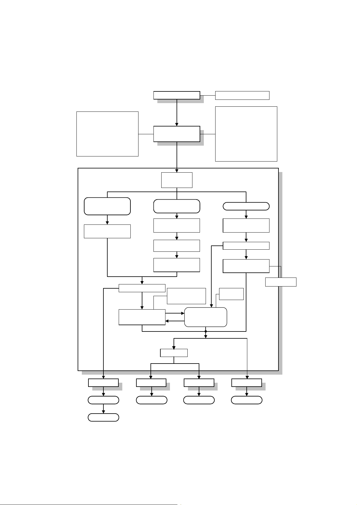
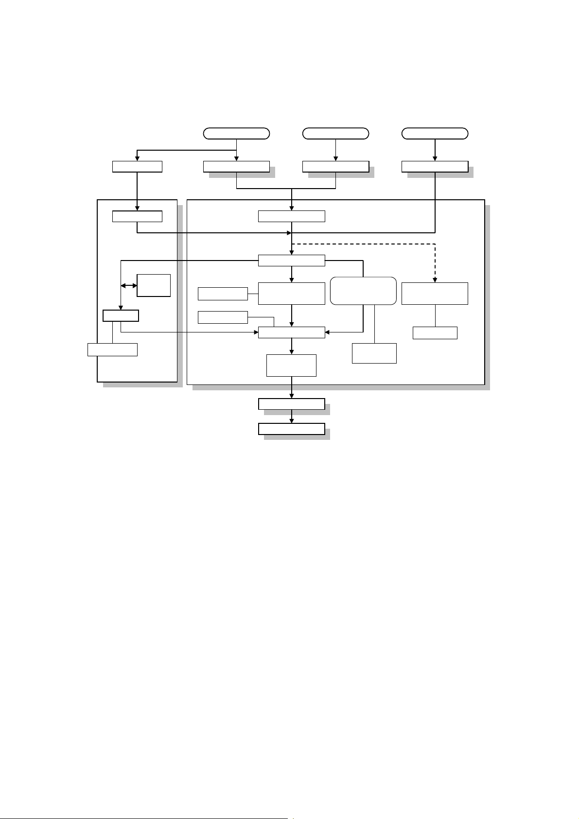
3.1.2 FLOW CHART................................................................................. 3-2
3.1.3 FAX OPTION TYPE 270 INSTALLATION ....................................... 3-3
3.2 OPTIONAL UNITS.................................................................................... 3-7
3.2.1 G3 INTERFACE UNIT TYPE 270.................................................... 3-7
3.2.2 ISDN OPTION TYPE 270.............................................................. 3-11
3.2.3 PC FAX EXPANDER (PCFE)........................................................ 3-14
3.2.4 FAX FUNCTION EXPANDER (EXFUNC)...................................... 3-16
3.2.5 EXPANSION MEMORY (EXMEM) BOARD................................... 3-18
3.2.6 HANDSET...................................................................................... 3-19
4. SERVICE TABLES......................................................................4-1
4.1 SERVICE LEVEL FUNCTIONS................................................................ 4-1
4.1.1 HOW TO ENTER AND EXIT THE FAX SERVICE MODE............... 4-1
4.1.2 BIT SWITCH PROGRAMMING (FUNCTION 01)............................. 4-1
4.1.3 SYSTEM PARAMETER LISTS (FUNCTION 02)............................. 4-2
4.1.4 FCU ROM VERSION DISPLAY (FUNCTION 02)............................ 4-4
4.1.5 MODEM PROGRAM VERSION DISPLAY (FUNCTION 02)............ 4-4
4.1.6 ERROR CODE DISPLAY (FUNCTION 03)...................................... 4-4
4.1.7 SERVICE MONITOR REPORT (FUNCTION 04)............................. 4-4
4.1.8 G3 PROTOCOL DUMP LIST (FUNCTION 05)................................ 4-5
4.1.9 G4 PROTOCOL DUMP LIST (FUNCTION 05)................................ 4-5
4.1.10 PC PROTOCOL DUMPLIST (FUNCTION 05)............................... 4-6
4.1.11 RAM DISPLAY AND REWRITE (FUNCTION 06).......................... 4-6
4.1.12 NCU PARAMETERS (FUNCTION 06)........................................... 4-7
4.1.13 RAM DUMP (FUNCTION 06)......................................................... 4-7
4.1.14 RAM CLEAR (FUNCTION 07)....................................................... 4-8
4.1.15 FCU REBOOT ............................................................................... 4-8
4.1.16 SERVICE STATION FAX NUMBER (FUNCTION 09) ................... 4-8
4.1.17 SERIAL NUMBER (FUNCTION 10)............................................... 4-9
4.1.18 MODEM TEST (FUNCTION 11).................................................... 4-9
4.1.19 V.34 MODEM TEST (FUNCTION 11).......................................... 4-10
4.1.20 DTMF TEST (FUNCTION 11)...................................................... 4-10
4.1.21 RINGER TEST (FUNCTION 11).................................................. 4-11
4.1.22 MEMORY TEST (FUNCTION 11)................................................ 4-11
4.1.23 DIU TEST (FUNCTION 11).......................................................... 4-12
4.1.24 FILE PRINTOUT (FUNCTION 13)............................................... 4-12
4.1.25 JOURNAL PRINTOUT (FUNCTION 14)...................................... 4-13
4.1.26 USAGE LOG PRINTOUT (FUNCTION 15).................................. 4-13
4.1.27 DATA TRANSFER (FUNCTION 16)............................................ 4-13
4.1.28 SG3-V34 (FUNCTION 17)........................................................... 4-14
4.2 BIT SWITCHES...................................................................................... 4-17
4.2.1 SYSTEM SWITCHES.................................................................... 4-17
4.2.2 SCANNER SWITCHES ................................................................. 4-31
4.2.3 PRINTER SWITCHES................................................................... 4-36
4.2.4 COMMUNICATION SWITCHES.................................................... 4-41
ii
Page 5

4.2.5 G3 SWITCHES.............................................................................. 4-52
4.2.6 SG3 SWITCHES............................................................................ 4-60
4.3 NCU PARAMETERS .............................................................................. 4-67
4.4 DEDICATED TRANSMISSION PARAMETERS..................................... 4-78
4.1.1 PROGRAMMING PROCEDURE................................................... 4-78
4.1.2 PARAMETERS.............................................................................. 4-79
4.5 SERVICE RAM ADDRESSES................................................................ 4-83
5. PREVENTIVE MAINTENANCE...................................................5-1
5.1 SPECIAL TOOLS AND LUBRICANTS ..................................................... 5-1
5.2 PM TABLE................................................................................................ 5-1
6. REMOVAL AND REPLACEMENT..............................................6-1
6.1 PRECAUTION.......................................................................................... 6-1
6.2 FCU .......................................................................................................... 6-1
6.2.1 REMOVAL....................................................................................... 6-1
6.2.2 SRAM DATA RESTORE FROM FCU.............................................. 6-3
6.2.3 SRAM DATA RESTORE FROM FLASH CARD BACKUP............... 6-4
6.3 NCU.......................................................................................................... 6-7
6.4 ROM UPDATE.......................................................................................... 6-8
6.4.1 FCU ROM DOWNLOAD.................................................................. 6-8
6.4.2 FCU ROM UPLOAD ...................................................................... 6-10
6.4.3 SG3 BOARD ROM DOWNLOAD................................................... 6-12
6.4.4 SG3 BOARD MODEM ROM DOWNLOAD.................................... 6-13
6.5 SRAM DATA BACKUP AND RESTORE................................................ 6-14
6.5.1 SRAM BACKUP TO A FLASH MEMORY CARD........................... 6-14
6.5.2 SRAM RESTORE FROM A FLASH MEMORY CARD................... 6-15
7. TROUBLESHOOTING.................................................................7-1
7.1 ERROR CODES....................................................................................... 7-1
7.2 FAX SC CODES..................................................................................... 7-10
7.2.1 OVERVIEW ................................................................................... 7-10
7.2.2 SC1201.......................................................................................... 7-10
7.2.3 SC1207.......................................................................................... 7-10
7.2.4 FAX SC CODE TABLE.................................................................. 7-11
iii
Page 6

20 September 1999 SPECIFICATIONS
1. OVERALL MACHINE INFORMATION
1.1 SPECIFICATIONS
Type
Desktop type transceiver
Circuit
PSTN, PABX, ISDN
Connection
Direct couple
Original Size (Book)
Maximum Length: 432 mm [17 ins]
Maximum Width: 297 mm [11.7 ins]
Original Size (ADF)
Length: 128 - 1200 mm [5.0 – 47.2 ins]
Width: 105 - 297 mm [4.1 - 11.7 ins]
Thickness: 40 - 128 g/m
Scanning Method
Flat bed, with CCD
Scan Width
210 mm [8.3 ins] ± 1% (A4)
216 mm [8.5 ins] ± 1% (8.5" x 11")
256 mm [10.1 ins] ± 1% (B4)
279 mm [11.0 ins] ± 1% (11" x 17")
297 mm [11.7 ins] ± 1% (A3)
Resolutions
8 x 3.85 lines/mm (G3 only)
8 x 7.7 lines/mm (G3 only)
8 x 15.4 lines/mm (G3 only)
16 x 15.4 lines/mm (G3 only)
200 x 100 dpi
200 x 200 dpi
400 x 400 dpi
Note:
To use the 8 x 15.4 lines/mm, 16 x 15.4
lines/mm and 400 x 400 dpi resolutions, an
optional EXMEM board is required.
2
[10 - 34 lbs]
Memory Capacity
ECM: 128 Kbytes
SAF:
Standard: 2 Mbytes (160 pages)
With optional memory board (EXFUNC +
EXMEM) :
30 Mbytes (3000 pages)
Measured using an ITU-T #1 test document
(Slerexe letter)
Compression
MH, MR, MMR
JBIG (EXFUNC and/or SG3 board required,
G3/ISDN G3 only)
(MMR only with ECM and G4)
SAF storage for memory tx: MMR and/or
raw data
Protocol
Group 3 with ECM
Group 4 (ISDN unit required)
Modulation
V.34, V.33, V.17 (TCM), V.29 (QAM),
V.27ter (PHM), V.8, V.21 (FM)
Data Rate (bps)
G3:
33600/31200/28800/26400/24000/21600/
19200/16800/14400/12000/9600/7200/4800
/2400, Automatic fallback
G4 (option): 64 kbps/56 kbps
I/O Rate
With ECM: 0 ms/line
Without ECM: 2.5, 5, 10, 20, or 40 ms/line
Transmission Time
G3: 3 s at 28800 bps; Measured with G3
ECM using memory for an ITU-T #1 test
document (Slerexe letter) at 8 x 3.85 l/mm
resolution
G4 (option): 3 s at 64 kbps; Measured with
an ITU-T #1 test document (Slerexe letter)
at 200 x 200 dpi resolution
Overall
Information
1-1
Page 7
FEATURES 20 September 1999
1.2 FEATURES
1.2.1 FEATURES LIST
KEY:
O = Used, X = Not Used,
(A = Optional EXMEM board required)
B = Optional EXFUNC board required
C = Optional PCFE board required
D = Optional ISDN unit required
E = Optional G3 unit required
Video Processing Features
Automatic image density
selection
Contrast O
Halftone
(Basic & Error Diffusion)
JBIG compression B or
MTF O
Reduction before tx O
Scanning Resolution –
Standard
Scanning Resolution – Detail O
Scanning Resolution – Fine A
Scanning Resolution –
Superfine
Smoothing to 400 x 400 dpi
when printing
Communication Features –
Automatic
Automatic fallback O
Automatic redialing
(Memory tx only)
Dual Access O
Length Reduction O
Resolutions available for
reception
Detail
Fine
Superfine
Substitute reception O
V34 communication O
O
O
E
O
A
O
O
O
A
A
Communication Features - User
Selectable
90° Image Rotation before tx
Action as a transfer
broadcaster
AI Redial (last ten numbers) O
Answering machine interface X
Authorized Reception O
Auto Document O
Automatic dialing
(pulse or DTMF)
Automatic Voice Message X
Batch Transmission O
Book Original tx O
Broadcasting O
Chain Dialing O
Communication Record Display O
Confidential ID Override O
Confidential Reception O
Confidential Transmission O
Direct Fax Number Entry O
Economy Transmission O
Fax on demand X
Forwarding O
Free Polling O
Groups (Standard: 9 groups) O
Hold X
ID Transmission O
Immediate Redialing O
Immediate Transmission O
ISDN D
Keystroke Programs O
Memory transmission O
Multi-step Transfer O
Non-standard original size
transmission
OMR X
On Hook Dial O
Ordering Toner X
Page Count O
Page separation mark O
Parallel memory transmission O
Partial Image Area Scanning X
O
X
O
O
1-2
Page 8
20 September 1999 FEATURES
Communication Features - User
Selectable
Personal Codes O
Polling Reception O
Polling Transmission O
Polling tx file lifetime in the SAF O
Quick Dial
O
(Standard: 56 stations)
Reception modes (Fax, Tel) O
Remote control features X
Remote Transfer X
Restricted Access O
Secured Polling O
Secured Polling with Stored ID
O
Override
Send Later O
SEP/SUB/PWD/SID O
Silent ringing detection X
Specified Image area X
Speed Dial
O
(Standard: 100 stations)
Stamp O
Telephone Directory O
Tonal Signal Transmission O
Transfer Request O
Transmission Deadline (TRD) O
Turnaround Polling X
Two in one O
Voice Request
X
(immed. tx only)
Communication Features -
Service Selectable
AI Short Protocol O
Auto-reduction override option O
Busy tone detection O
Cable Equalizer O
Closed Network O
Continuous Polling Reception O
Dedicated tx parameters O
ECM O
EFC X
Inch-mm conversion before tx O
Length Reduction O
Page retransmission times O
Protection against wrong
O
connection
Communication Features -
Service Selectable
Short Preamble X
Other User Features
Area code prefix X
Center mark O
Checkered mark O
Clearing a memory file O
Clearing a polling file O
Clock O
Confidential ID O
Counters O
Daylight Saving Time O
Destination Check X
Direct entry of names O
Energy Saver O
File Retention Time O
File Retransmission O
Function Programs (F1 – F4) O
Hard Disk Filing System X
ID Code O
Label Insertion ("To xxx") O
Language Selection SP
mode
Memory Lock O
Modifying a memory file (tx) O
Multi Sort Document Reception X
Own telephone number O
Print density control X
RDS on/off O
Reception Mode Switching
X
Timer
Reception time printing O
Remaining memory indicator O
Reverse Order Printing O
RTI, TTI, CSI O
Service Report Transmission O
Speaker volume control O
Specified Cassette Selection O
Substitute reception on/off O
Telephone line type O
Toner Saving Mode X
TTI/CIL on/off O
User Function Keys (4 keys) O
User Parameters O
Overall
Information
1-3
Page 9
FEATURES 20 September 1999
Other User Features
Wild Cards O
Reports - Auto ma tic
Charge Control Report X
Communication Failure Report O
Confidential File Report O
Error Report O
Fax On Demand Report X
File Clear Report O
File Reserve Report O
Journal O
Polling Result Report O
Power Failure Report O
Transfer Result Report O
Transmission Result Report O
Reports - User-initiated
Authorized Reception List O
Charge Control Report X
File List O
Forwarding List O
Group List O
Hard Disk File List X
Journal O
Personal Code List O
Program List O
Quick Dial Label O
Quick Dial List O
Specified Cassette Selection
List
Speed Dial List O
Transmission Status Report X
User Function List X
User Parameter List O
X
Service Mode Features
Echo countermeasure O
Effective term of service calls O
Error code display O
Excessive jam alarm O
File Transfer (all files) O
LCD contrast adjustment
Line error mark X
Memory file printout (all files) O
Modem Software Download
Modem test (includeV.34 / V.8) O
NCU parameters O
Periodic service call O
PM Call O
Printing all communication
records kept in memo ry
Protocol dump list O
RAM display/rewrite O
RAM dump O
RAM test O
RDS
- RAM read/write
- Dial data transfer
(Quick/Speed)
- Software transfer
Ringer test O
ROM version display (FCU) SP
Serial number O
Service monitor report O
Service station number O
Software Upload/Download O
SRAM data backup/restore O
System parameter list O
Technical data on the Journal O
SP
mode
*1
O
O
O
O
mode
Service Mode Features
Back-to-back test O
Bit switch programming O
Cable equalizer O
Comm. parameter display O
Counter check SP
mode
Country code O
DTMF tone test O
1-4
Modem Software Download is
:
*1
available only for the optional G3
interface unit.
Page 10

20 September 1999 FEATURES
1.2.2 CAPABILITIES OF PROGRAMMABLE ITEMS
The following table shows how the capabilities of each programmable item will
change after the optional function upgrade card is installed.
Item Standard
Maximum number of memory files 200 1000
Maximum number of destinations
per file
Maximum number of destinations
overall
Maximum number of pages overall 400 3000
Number of Quick Dials 56 56
Number of Speed Dials 100 1000
Number of Groups 9 30
Maximum number of destinations
per Group
Maximum number of destinations
dialed from the ten-key pad overall
Maximum number of programs 56
(programmed in 5 6
Quick Dial keys)
Maximum number of Auto
Documents
Maximum number of communication
records for the TCR (Journal) store d
in the memory
Maximum number of addresses
specified for features such as
Authorized Reception and Specified
Cassette Selection
Maximum number of user function
keys
Maximum number of personal codes 20 50
(programmed in 6
Quick Dial keys)
256 500
300 2000
256 500
100 1000
6
100 900
30 50
44
With optional boards
(EXFUNC + EXMEM)
56
(programmed in 5 6
Quick Dial keys)
18
(programmed in 1 8
Quick Dial keys)
1-5
Page 11
OVERALL MACHINE CONTROL 20 September 1999
1.3 OVERALL MACHINE CONTROL
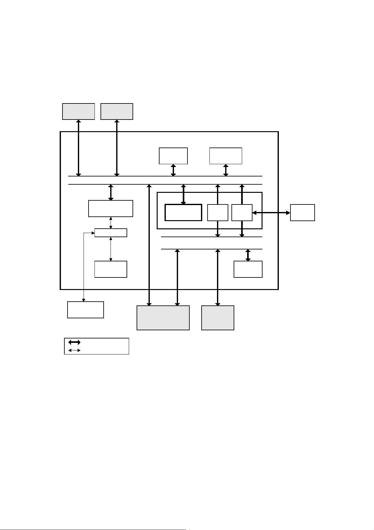
1.3.1 SYSTEM CONTROL
SG3
ISDN
V.34 MODEM
Analog Circuit
NCU
FCU
SRAM
(128kB)
CPU BUS
FACE
CPU (RU30)
Flash ROM
(2MB)
DCR
DMA BUS
VIF
DRAM
(8MB)
BiCU
Monitor
Speaker
Bus Interface
Parallel Interface
EXFUNC
Board
(512kB)
EXMEM
Board
(32MB)
A895V500.WMF
1-6
Page 12

20 September 1999 OVERALL MACHINE CONTROL
The basic fax unit consists of two PCBs: an FCU and an NCU.
The FCU controls all the fax communications and fax features, in cooperation with
the base copier's main board, the BiCU. The NCU switches the analog line
between the fax unit and the external telephone.
Fax Options
1. EXFUNC board: JBIG compression becomes available. In addition, this
expands the system's SRAM capacity to hold programmed telephone numbers,
communication records, etc.
2. PC fax expander: Class 2 fax communication from a PC and local printing from
a PC fax application become available (PC fax application required). Also, local
scanning from the machine’s scanner using TWAI N API beco mes av ai l able
(CFM Twain driver required).
3. ISDN unit: This allows the fax unit to communicate over an ISDN (Integrated
Services Digital Network) line.
4. EXMEM board: This expands the SAF memory capacity. Also, this expands the
page memory capacity to enable 400 dpi communications.)
5. SG3 unit: This provides one more analog line (PSTN) interface. This allows full
dual access (two communications can be made at the same time).
1.3.2 POWER DISTRIBUTION AND CONTROL
The FCU power is supplied from the base copier's BiCU (+2 4V, +12V, -12V, and
+5V). Refer to the base copier's service manual for details.
1.3.3 MEMORY BACK-UP
The system parameters and programmed items in the SRAM on the FCU and the
EXFUNC board are backed up by batteries (long-term backup), in case the base
copier's main switch is turned off.
The SAF memory (DRAM) on the FCU and the EXMEM board are backed up by
rechargeable batteries for 1 hour.
1-7
Page 13
VIDEO DATA PATH 20 September 1999
1.4 VIDEO DATA PATH
1.4.1 TRANSMISSION
Memory Tx
Auto Shading
Gamma Correction
MTF
Graduation Processing
Main Scan Reduction
- 400 to 200 dpi
Thresholding
Memory Tx
without image
rotation
FACE
(DCMMR)
FCU
Scanner
BiCU
Sub Scan Magnification
Immediate Tx
Auto Shading
Gamma Correction
MTF
Graduation Processing
Main Scan Reduction
- 400 to 200 dpi
- Inch-mm Conversion
- A3 to B4, A3 to A4, B4 to A4
Thresholding
FACE
(VIF)
Memory Tx
with Image Rotation
FACE FACE
Page Memory
(Rotation)
FACE
(DCMMR)
Immediate Tx
Page Memory
FACE
(DCR)
Analog G3
SAF Memory
FACE
(DCR)
Decompression
Compression
(Main Scan Reduction)
EXFUNC board
QM-CODER
(Optional)
Modem
ISDN G3Analog G3NCU-2
JBIG
Compression
CiG4CiG4NCUSG3
ISDN G4
Compression
A895V501.WMF
1-8
Page 14

20 September 1999 VIDEO DATA PATH
Memory Transmission and Parallel Memory Transmission
The base copier's scanner scans the original at the selected resolution in inch
format. The BiCU processes the data and transfers it to the FCU.
NOTE:
Then, the FCU converts the data to mm format, and compresses the data in MMR
or raw format to store it in the SAF memory. If image rotation will be done (see
section 2-2-2), the image is rotated in page memory before compression.
At the time of transmission, the FCU decompresses the stored data, then recompresses and/or reduces the data if necessary for transmission. Either the NCU
or CiG4 (optional) transmits the data to the line.
When scanning a fax original, the BiCU uses the MTF and thresholding
parameter settings programmed in the fax unit’s scanner bit switches, not
the copier's SP modes.
Immediate Transmission
The base copier's scanner scans the original at the resolution agreed with the
receiving terminal. The BiCU video processes the data and transfers it to the FCU.
NOTE:
Then the FCU stores the data in page memory, and compresses the data for
transmission. Either the NCU or CiG4 (optional) transmits the data to the line.
When scanning a fax original, the BiCU uses the MTF and thresholding
parameter settings programmed in the fax unit’s scanner bit switches, not
the copier's SP modes.
Note that ISDN G3 tx is not possible on the PSTN-2 line.
JBIG Transmission
•
Memory transmission:
from the FACE (DCR) to the EXFUNC board for JBIG compression. Then either
the NCU or CiG4 (ISDN G3) transmits the data to the line. When an optional G3
unit (SG3) is installed and PSTN2 is selected as the line type, JBIG compression
is available, but only for the PSTN-2 line.
•
Immediate transmission:
from the page memory to the EXFUNC board for JBIG compression. Then either
the NCU or CiG4 (ISDN G3) transmits the data to the line. When an optional G3
unit (SG3) is installed and PSTN2 is selected as the line type, JBIG compression
is available, but only for the PSTN-2 line.
If the receiver has JBIG compression, the data goes
If the receiver has JBIG compression, the data goes
Adjustments
•
Line used for G3 transmissions (PSTN or ISDN): System switch 0A bit 6
•
Line used for G3 transmissions (PSTN 1/PSTN 2): System switch 16 bit 1
•
Use of the PSTN-2 line (rx only, or both tx and rx): Communication switch 16 bit
5
•
G3 line type: User parameter switch 6, bits 2 and 3
If this is at G3 auto selection, the machine can use either PSTN-1 or PSTN-2
If this is at PSTN-1, the machine will only use the PSTN-1 line.
1-9
Page 15
VIDEO DATA PATH 20 September 1999
1.4.2 RECEPTION
Analog G3 ISDN G3 ISDN G4
NCU-2
Modem
CCP
Decompression
SG3
QM-
CODER
NCU CiG4 CiG4
FCU
Decompression
Image Rotation
Modem
SAF Memory
FACE
(DCR)
Page Memory
FACE
(VIF)
BiCU
Printer
EXFUNC Board
QM-CODER
(Optional)
JBIG
compression
FACE
(DCR)
Error Check
A895V502.WMF
First, the FCU stores the incoming data from either an analog line or an ISDN line
to the SAF memory. (The data goes to the FACE at the same time, and is checked
for error lines/frames.)
The FCU then decompresses the data and transfers it to page memory. If image
rotation will be done (see section 2-2-2), the image is rotated in the page memory.
The data is transferred to the BiCU.
If the optional G3 unit is installed, the line that the message comes in on depends
on the telephone number dialled by the other party (the optional G3 unit has a
different telephone number from the main fax board).
Note that ISDN G3 rx is not possible on the PSTN-2 line.
JBIG Reception
When data compressed with JBIG comes in on PSTN-1 (the standard analog line),
the data is sent to the EXFUNC board for decompression. Then the data is stored
in the page memory, and transferre d to the BiCU.
When data compressed with JBIG comes in on PSTN-2 (optio nal extra analog
line), the data is sent to the QM-CODER on the SG3 board for decompression.
1-10
Page 16
20 September 1999 VIDEO DATA PATH
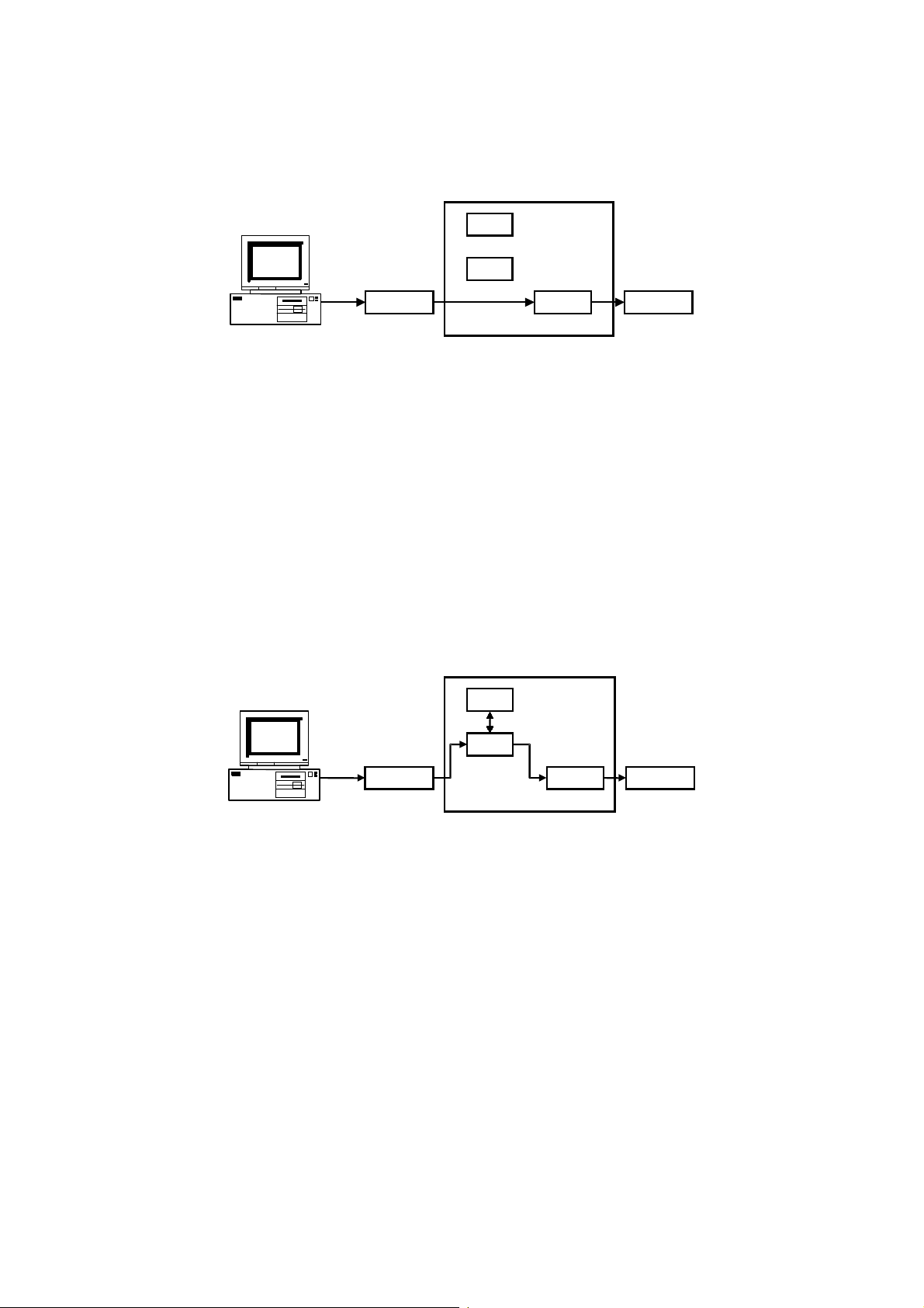
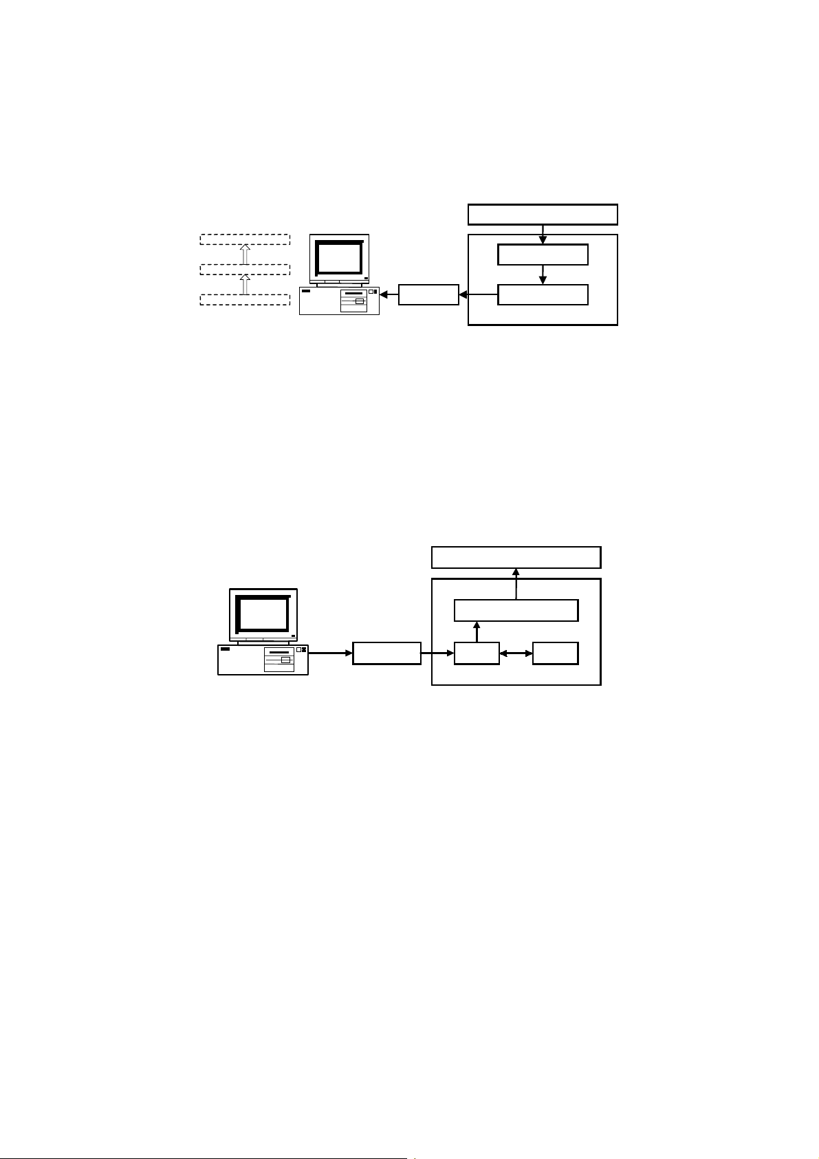
1.4.3 PC FAX COMMUNICATION
Direct transmission
SAF
DCR
IBM Compatible
FCU
ModemDIU
NCU
A895V503.WMF
The host computer sends commands and image data to the machine through the
DIU during transmission.
NOTE:
1) Group dials programmed in the machine cannot be used.
2) T.30 optional protocols (e.g., BFT) are not supported by class 2 fax
communication.
3) ISDN G4 numbers programmed in quick or speed dials cannot be used.
4) If ISDN is selected for G3 communication (system switch 0A, bit 6), the
G3 numbers must have been programmed in quick or speed dials.
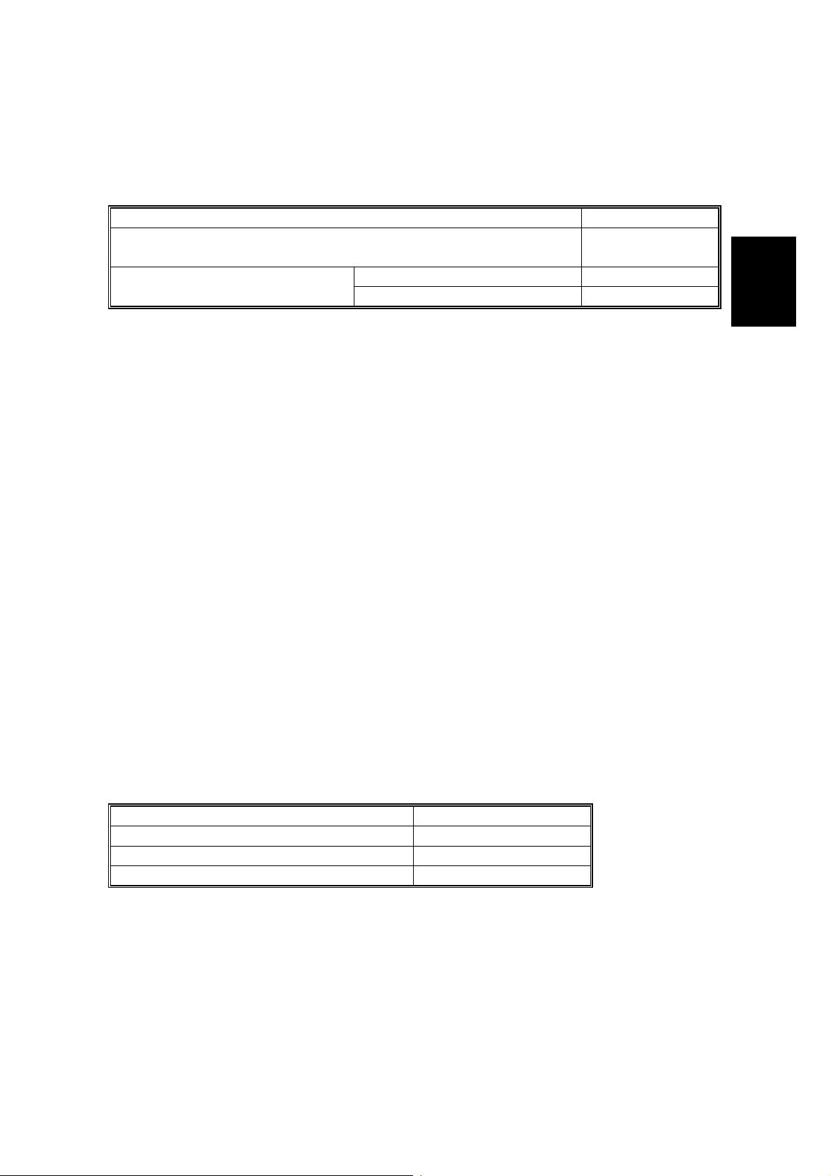
Memory transmission
SAF
DCR
IBM Compatible
FCU
ModemDIU
NCU
A895V504.WMF
The host computer sends destination number(s) and image data to the machine
through the DIU during transmission. The machine stores the image in the SAF
memory, then makes a fax transmission.
NOTE:
1) If the memory overflows while storing the first page into SAF memory,
the machine does not start the transmission.
2) If the memory overflows while storing the second or subsequent page
into SAF memory, the machine transmits all the successfully stored
pages.
3) When fax numbers programmed in the machine’s quick or speed dials
are specified using the PC fax application, all the specified numbers
must have been programmed in the fax machine.
4) T.30 optional protocols (e.g., BFT) are not supported by class 2 fax
communication.
1-11
Page 17
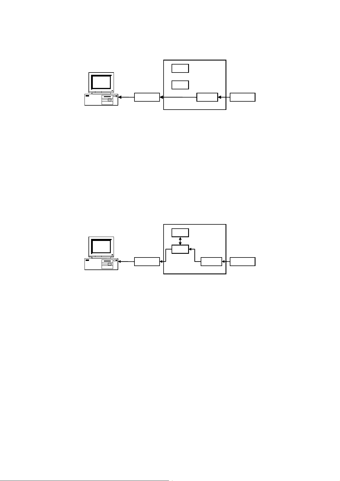
VIDEO DATA PATH 20 September 1999
Direct reception
SAF
DCR
IBM Compatible
FCU
ModemDIU
NCU
A895V505.WMF
The machine transfers received image data directly to the host PC without storing it
into SAF memory.
NOTE:
1) If the host PC is not ready to receive a fax message, the machine
receives the message into SAF memory.
2) Even if the SAF memory is full, the machine starts fax reception.
However, the machine will not continue re ception if the host computer is
not ready to receive a message.
3) The “Number of rings to answer” parameter in the PC fax application
must not exceed 4.
Memory reception
SAF
FCU
DCR
ModemDIU
IBM Compatible
NCU
A895V506.WMF
The machine receives a fax message in the SAF memory, then transfers data to
the host computer after the reception has finished. The machine prints the received
message after transferring data to the host if user parameter 21 – bits 1 and 2 are
set to “1: Print”.
NOTE:
1) If an error occurs due to cable disconnection, the PC fax application
must be restarted to receive the message.
2) Memory reception is not possible when forwarding is enabled.
3) Manual reception from the PC fax application is not supported.
4) The “Number of rings to answer” parameter in the PC fax application
must not exceed 4.
Adjustments
•
PC transmission mode (direct or memory): User parameter 20 (14H), bit 0
•
Line for PC transmission (PSTN 1/PSTN 2): User parameter 20 (14H), bit 4
•
Line for PC memory transmission (PSTN/ISDN G4): User parameter 20 (14H),
bit 5
•
PC fax reception mode (direct/memory): User parameter 21 (15H), bits 1 and 2
1-12
Page 18
20 September 1999 VIDEO DATA PATH
1.4.4 SCANNING AND PRINTING
SCANNING
Scanner
Application
Twain Driver
Serial Port
Page Memory
DCRDIU
IBM Compatible
A895V507.WMF
FCU
The machine scans an original into page memory, then transfers the data to the
host PC. The data is sent to the application through the CFM Twain driver.
NOTE:
The maximum resolution is 200 x 200 dpi.
PRINTING
Printer Engine
FCU
Page Memory
DCRDIU SAF
IBM Compatible
A895V508.WMF
The machine receives print data into SAF memory as fax image data, then prints it
after all the data has been transferred from the host PC.
The destination number “0000” informed from the host PC identifies a print job.
NOTE:
1) If SAF memory runs out while receiving print data, the machine prints up
to the successfully received data.
2) The machine cannot receive print data while printing a message from
the SAF memory. The data will be received af ter printing.
3) If a fax destination is specified together with the print destination “0000”,
the destinations specified after “0000” will be delayed until the machine
prints all pages in the message.
1-13
Page 19

20 September 1999 AUTOMATIC SERVICE CALLS
2. DETAILED SECTION DESCRIPTIONS
2.1 AUTOMATIC SERVICE CALLS
2.1.1 SERVICE CALL CONDITIONS
The fax unit makes an automatic service call when the base copier’s BiCU
generates any SC code except for those stored in the following RAM.
NOTE:
Exceptions
Address (H) Defi nition Default SC code
The service station’s fax number has to be programmed in advance, or the
machine cannot make a service call.
680DC8 1st SC code - High byte (BCD) 01
680DC9 1st SC code - Low byte (BCD) 92
680DCA 2nd SC code - High byte (BCD) 09
680DCB 2nd SC code - Low byte (BCD) 80
680DCC 3rd SC code - High byte (BCD) 09
680DCD 3rd SC code - Low byte (BCD) 99
680DCE
to
680DEF
4th SC code - High byte (BCD)
to
20th SC code - Low byte (BCD)
FF(H)
Automatic SBU adjustment
Program loading error
Program version error
Not Programmed
192
error
980
999
Detailed
Descriptions
To add additional SC codes, program them in the blank addresses.
Wild Cards
This function allows “A” or “a”, to be used as a wild card instead of numbers from 0
to 9. For example, “1AA” or “1aa” means all the SC codes from 100 to 199, and
“39A” or “39a” means all the SC codes from 390 to 399.
The fax unit cannot make an automatic service call when a Fax SC code condition
has occurred. Refer to the Troubleshooting section for Fax SC code details.
Manual Service Call
If the service station needs a report, the user can make a service call manually, by
changing bit 7 of User Parameter 14 (0E) to “1”.
2-1
Page 20

AUTOMATIC SERVICE CALLS 20 September 1999
A sample auto service report
* * * Auto Service Report (Date and Time) * * *
ProblemReason of the call - "SC Code" or "PM Call"
S C Latest 10 copier's SC codes
J A M BJ A M 2FEED 0000000000
Total print counter
Paper Feed Station
Jam Location
Service Monitor Report Contents
System Parameter List Contents
A895D500.WMF
2-2
Page 21
20 September 1999 AUTOMATIC SERVICE CALLS
2.1.2 PERIODIC SERVICE CALL
The periodic service call notifies the service station of the machine’s condition. The
call is made at a time interval programmed in the following RAM addresses:
Parameters Address (H)
Call interval: 01 through 15 months (BCD)
00: Periodic service call disabled
Date and time of the next call
Day: 01 through 31 (BCD)
Hour: 01 through 24 (BCD)
6803A1
6803A4
6803A5
To change these settings after programming, change the call interval. The machine
then automatically changes the remaining parameters by referring to the interval
and the current date and time.
2.1.3 PM CALL
Detailed
Descriptions
If PM alarm is enabled with the base copier’s SP mode and PM call is enabled with
system switch 01, the machine will make an automatic service call when the base
copier’s PM counter reaches the PM interval.
Cross reference
•
PM service call on/off: System switch 01, bit 0
•
PM alarm setting: SP mode 5-501 (default: 120K)
2.1.4 EFFECTIVE TERM OF SERVICE CALLS
If a time limit for the effectiveness of service calls is programmed, the machine
stops making automatic service calls after the time limit.
Program the time limit at the following addresses. This function is disabled when all
of these addresses are 00(H).
Parameters Address (H)
Year: last two digits of the year (BCD) 6803AB
Month: 01 through 12 (BCD) 6803AC
Day: 01 through 31 (BCD) 6803AD
2-3
Page 22

SCANNING FEATURES 20 September 1999
2.2 SCANNING FEATURES
2.2.1 PAGE SPLIT TRANSMISSION (BOOK TRANSMISSION)
U s e r pa ra me te r s w itch 0 6 ,
bit6=1 (Default)
U s e r pa ra me te r s w itch 0 6 ,
Bit6=0
2
1
1
2
A895D502.WMF
This function allows a B4, A4/8.5 x 11", or A3/11 x 17" size book original to be sent
as two separate pages.
When this function is selected, the machine scans the original twice and transmits
the pages in the same sequence as they were scanned.
With the default setting, the right page is sent first, then the left page is sent. If the
setting is changed, the order is reversed.
Cross Reference
•
Scanning start page – User parameter switch 06, bit 6
The default setting is 1 (start scanning from the right).
NOTE:
1) This function is only possible when sending a book original from the
exposure glass.
2) If this function is used for an A3 or 11 x 17" original, the pages may be
transmitted in a lengthwise direction, depending on the setting of "Image
Rotation before Transmission" (see the next page).
2-4
Page 23
20 September 1999 SCANNING FEATURES
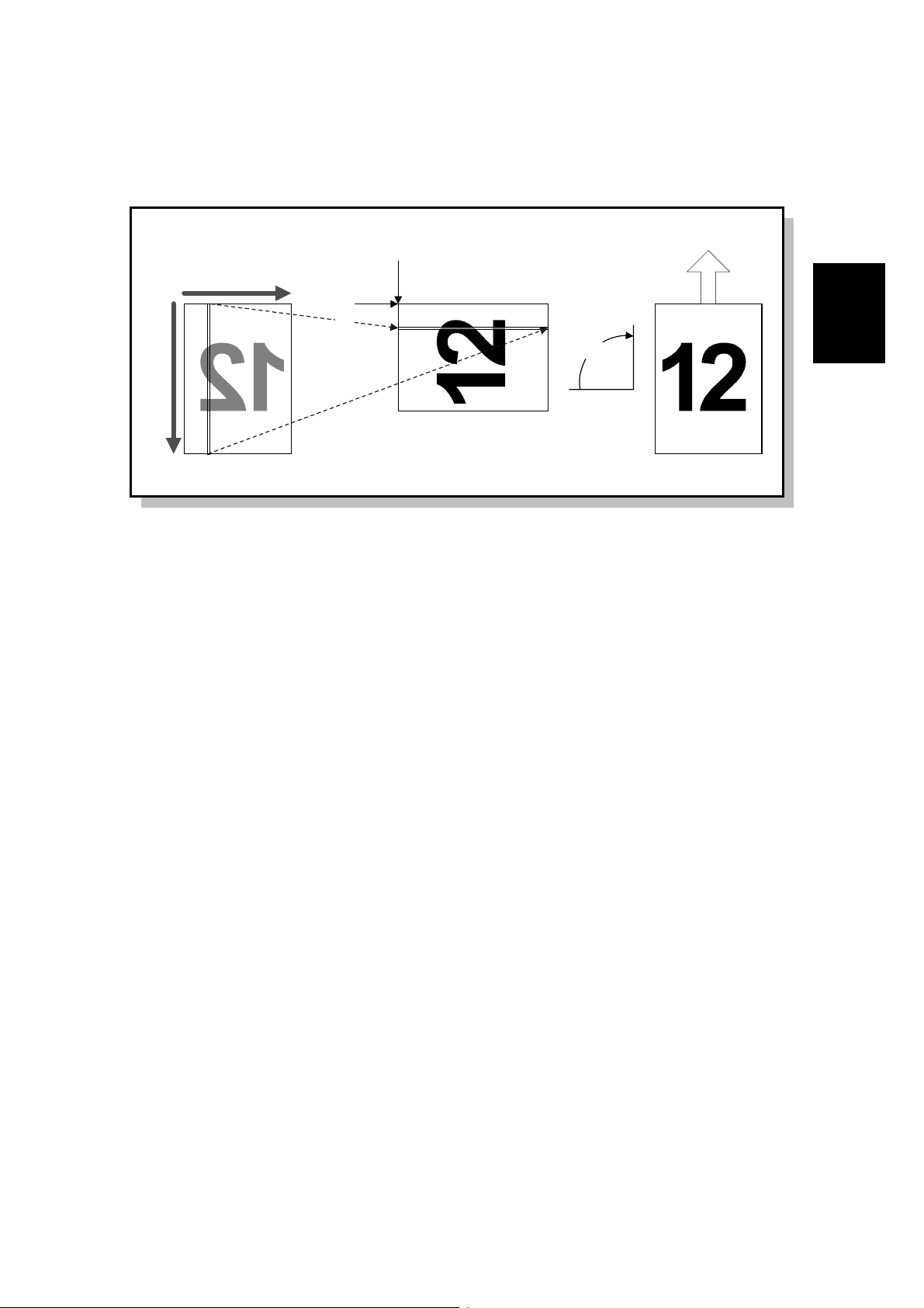
2.2.2 IMAGE ROTATION BEFORE TRANSMISSION
Sub Scan
(< 210mm/8.5")
Main Scan
(297mm/11")
1st Pixel
1st Line
90°
Scanned ImageOriginal Transmitted Image
A895D503.WMF
A4 or 8.5 x 11" sideways
This function avoids the unintentional reduction of an A4 or 8.5 x 11” sideways
original. When the machine detects a sideways A4 or 8.5 x 11" original in the ADF
or on the exposure glass, the fax unit rotates the scanned image clockwise by 90
degrees before transmission, as shown above.
Detailed
Descriptions
A5 or HLT lengthwise/B5 lengthwise
This function prevents blank spaces at the sides of the received image. When the
machine detects an A5 or HLT original placed lengthwise in the ADF or on the
exposure glass, the fax unit rotates the scanned image clockwise by 90 degrees
before transmission, as shown above.
2-5
Page 24

SCANNING FEATURES 20 September 1999
NOTE:
1) Even if Parallel Memory Transmission is enabled, the machine uses
normal memory transmission to send an A4 or 8.5 x 11" sideways
original.
2) If the machine carries out this function while printing, the machine stops
printing until scanning is completed.
3) The machine determine s if it will rotate the image after the paper size is
determined.
4) This feature is not performed during parallel memory transmission.
5) In Book mode, the machine determines image rotation for each page
scanned.
In ADF mode, the machine determines image rotation for the first page.
If it is rotated, all pages will be rotated. If the first page need not to be
rotated, all pages will not be rotated.
6) When this feature is enabled for A5 or HLT lengthwise, “APS small
original detection” must be changed. This allows the machine to detect
an A5/HLT size original. With the default setting, the machine does not
detect A5 or HLT lengthwise in book mode.
Cross Reference
•
Image rotation before Tx A3 or 11” width original on/off
- Scanner switch 0F, bit 0 (Default setting is enabled)
•
Image rotation before Tx A5 or HLT width original on/off
- Scanner switch 0F, bit 2 (Default setting is disabled)
•
Image rotation before Tx B5 width original on/off
- User Parameter switch 19 (13H), bit 3 (Default setting is disabled)
•
APS small size original detection
•
Base copier’s SP 4-303 (Default setting is “Not detected”)
•
Scanner switch 0C, bits 1 and 2
(Default setting is “Depends on the setting of the base copier”)
2-6
Page 25
20 September 1999 SCANNING FEATURES
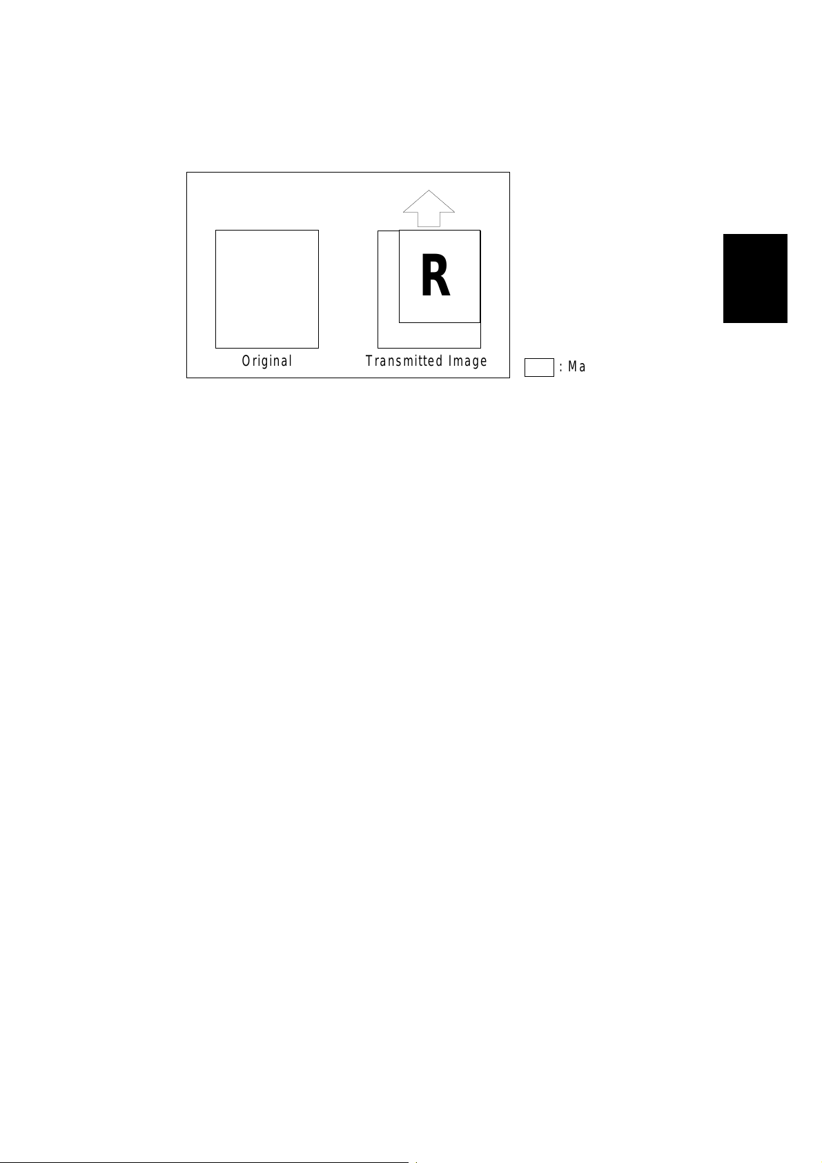
2.2.3 CREATE MARGIN TRANSMISSION
R
R
Detailed
Descriptions
Original Transmitted Image
: Margin
A895D536.WMF
When this function is enabled, the scanner is able to reduce the image of the
original. This allows the person at the other end to file the printout without losing
any of the data to punch holes.
The machine adds a margin to the bottom and left borders of the image so that the
transmitted page is the same size as the original.
Cross reference
•
Reduction ratio - System switch 06 bit 0 to 7
Default setting is 93% (71 to 99%)
NOTE:
1) This function is only possible during memory transmission.
2) “Create margin transmission” and “Image rotation before transmission”
are not compatible. (Create margin transmission is given priority)
3) The sample image on reports is also reduced and contains the margin.
4) Both the main and sub scan directions use the same magnification ratio.
2-7
Page 26

PRINTING FEATURES 20 September 1999
2.3 PRINTING FEATURES
2.3.1 PAPER SIZE SELECTION
This section explains how the FCU selects the appropriate paper size for printing a
received fax image.
Width Priority and Length Priority
When “Width Priority” is selected , a paper size of the same width as the re ceived
fax image has a higher priority. The fax image may be printed on several pages.
When “Length Priority” is selected, a paper size that has enough length to print the
received fax image has higher priority. The fax image is printed on one sheet of
paper, but the printed fax may have wide margins on the left and right.
Cross Reference
•
Paper selection priority - Printer switch 0E, bit 0 (Default: Width)
•
Paper size selection priority for an A4 size fax message when A4/LT size paper
is not available. - User Parameter switch 16 (10H), bit 2
0: A3 has priority (Default setting), 1: B4 has priority
Image Rotation Before Printing
If the machine has the same size paper as the received fax image size, but in
sideways orientation, the fax unit rotates the image by 90 degrees clockwise, and
prints it sideways.
This feature is only possible when the received fax image is one of the following
sizes: A4 lengthwise, 8.5 x 11" lengthwise, B5 lengthwise
NOTE:
This function can not be disabled.
2-8
Page 27
20 September 1999 PRINTING FEATURES
Sub-Scan Reduction and Page Separation
Sub-scan Reduction Disabled
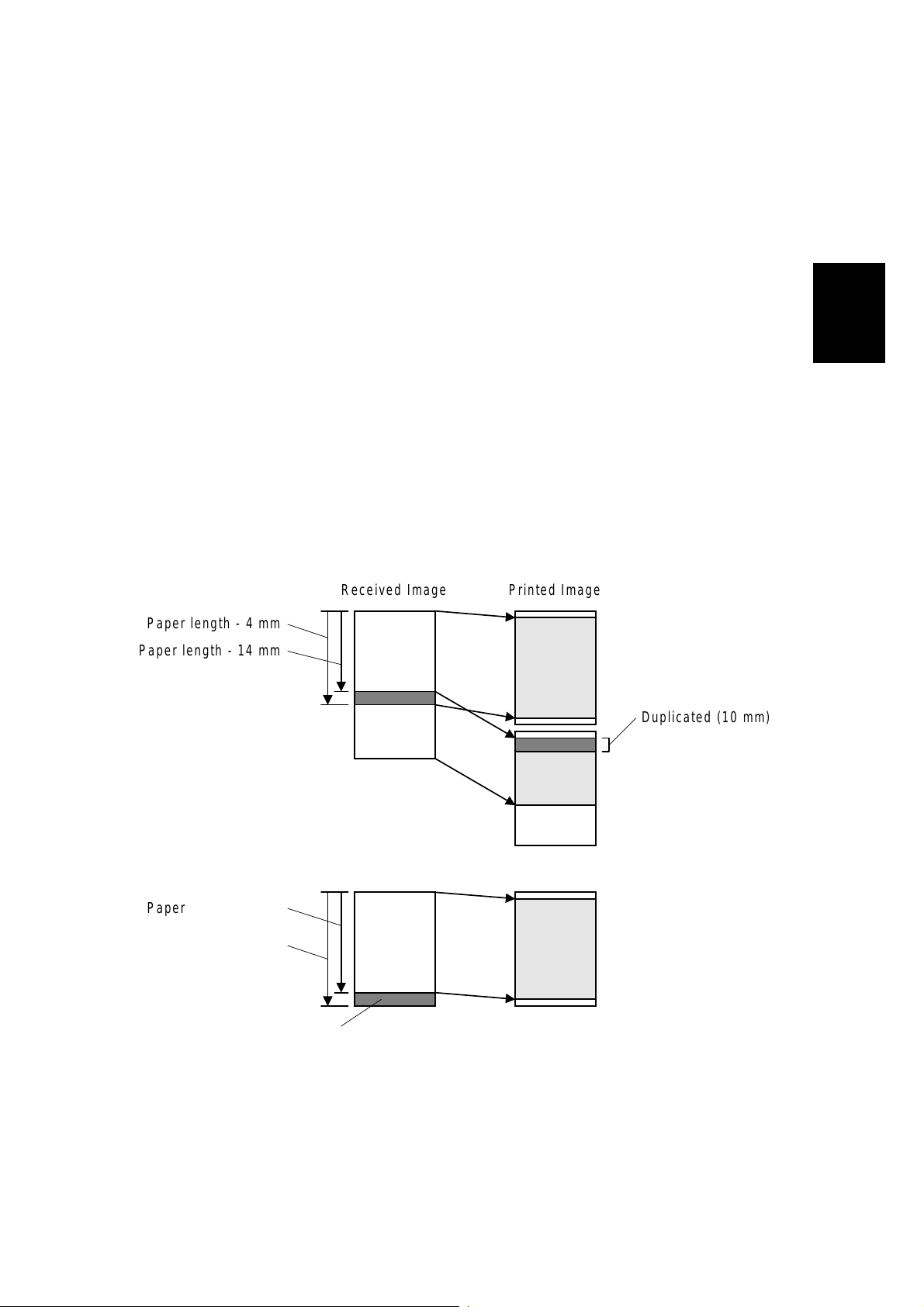
When Sub-scan Reduction is disa bled, the received fax image is printed
unreduced.
If the image is longer than the paper length + 6 mm, the image is separated onto
two pages (see the top drawing below).
If the image is shorter than the paper length + 6 mm but longer than the paper
length - 4 mm, the part of the image after paper length - 4 mm will be lost (see the
bottom drawing below).
NOTE:
The page separation threshold is adjustable between 0 and 15 mm (the
default is paper length + 6 mm). Refer to Printer Switch 03, bits 4 to 7 for
more details.
The 2 mm gaps at the leading and trailing edges depend on the leading
and trailing edge margin settings.
The 10 mm image duplicati on can be adj usted or disabled.
Detailed
Descriptions
Paper length - 4 mm
Paper length - 14 mm
Paper length - 4 mm
Within
Paper length +6 mm
Not printed
Received Image Printed Image
Duplicated (10 mm)
Received Image Printed Image
2-9
A895D505.WMF
Page 28
PRINTING FEATURES 20 September 1999
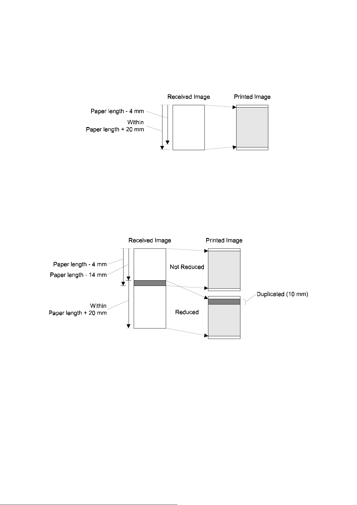
Sub-scan Reduction Enabled
When Sub-scan Reduction is enab l ed, the received fax image is reduced in the
page memory to fit on the selected paper, if the received image length is between
[paper length - 4 mm] and [paper length + 20 mm]. See the drawing below.
A895D525.WMF
NOTE:
The upper limit (page length +20 mm) is adjustable between 0 and 155
mm. Refer to Printer Switch 04, bits 0 to 4 for more details.
If the FCU detects that the image must be separated into more than one page after
reduction, what happens to the data depends on the Reduction Rate Equalization
setting (Printer Switch 0E, bit 7).
- Reduction Rate Equalization Off (Example Diagram: Two-page Printout) -
A895D524.WMF
1. The data up to [page length –4 mm] will be printed on page 1, without
reduction.
2. The last 10 mm of this data will be repeated at the top of the next page (this
length can be can be adjusted or repetition can be switched off).
3. The remaining data will be printed on page 2, with reduction, if it is within
[paper length + 20 mm].
4. If it is longer than this, page separation is done again. Data up to [page length 4 mm] will be printed on page 2, without reduction.
5. The process for page 3 and subsequent pages will repeat from step 2.
2-10
Page 29
20 September 1999 PRINTING FEATURES
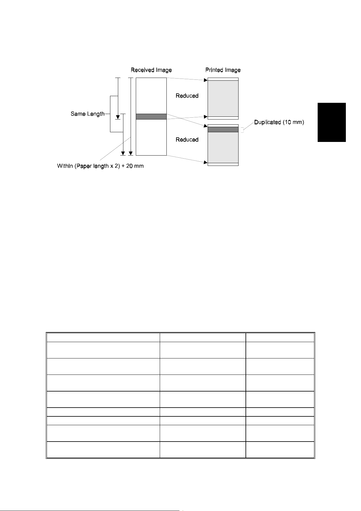
- Reduction Rate Equalization On (Example Diagram: Two-page Printout) -
A895D528.WMF
1. The machine determines how many pages will be needed to print the message,
taking the following into account:
Detailed
Descriptions
The final page (n) is such that the received image length is within (paper length x n)
+ 20 mm
The data must be reduced to fit on pages of length (paper length - 4 mm), with an
equal reduction rate for each page.
The last 10 mm of the previous page will be repeate d at the top of the next page
(this length can be adjusted or repetition can be disabled).
2. The machine prints all the pages, at the same reduction rate.
If the customer does not want to receive a fax message on separate pages, page
separation can be disabled. However, once it has been disabled, the machine does
not print the received fax message until a paper size which can hold the received
fax image on one page is set in a cassette. Keep page separation enabled if the
customer expects to receive fax messages longer than the installed paper.
Cross Reference
Parameter Switch Default Setting
Reduction in sub-scan direction
on/off
Equalizing reduction rate among
separated pages
Page separation threshold when
reduction is disabled
Page separation threshold when
reduction is enabled
Page separation on/off Printer Switch 0E, bit 2 Enabled
Page separation mark on/off Printer Switch 00, bit 0 Enabled
Image duplication with page
separation, on/off
Length of the repeated image on
the next page
Printer Switch 03, bit 0 Enabled
(except Germany)
Printer Switch 0E, bit 7 Enabled
Printer Switch 03, bits 4-7 6 mm
Printer Switch 04, bits 0-4 20 mm
Printer Switch 00, bit 1 Enabled
Printer Switch 04, bits 5-6 10 mm
2-11
Page 30
PRINTING FEATURES 20 September 1999
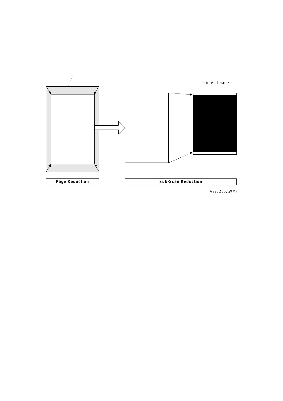
Page Reduction
This function allows a received fax image to be printed on paper with less width
than the fax image.
Received Image
Printed Image
Reduced Image
Page Reduction Sub-Scan Reduction
Reduced Image
A895D507.WMF
First, the received image is reduced by a fixed reduction rate in the main and subscan directions. The available reduction rates are as follows:
•
84% - A3 to B4 reduction
•
82% - B4 to A4 lengthwise reduction
Then, the reduced image is further reduced (if necessary) in the sub-scan direction
so that it can be printed on one page. However, if the FCU detects that the image
does not fit on one page after sub-scan reduction, the FCU cancels the page
reduction, but uses normal sub-scan reduction on the received fax image.
NOTE:
1) Sub-scan reduction is automatically enabled when Page Reduction is
enabled.
2) A3 to A4 reduction is not available.
Cross Reference
•
Page reduction on/off - User parameter 10 (0A), bit 3 (Default: Disabled)
2-12
Page 31

20 September 1999 PRINTING FEATURES
Examples
1. When printing a B4 size fax image on 8.5" x 11" lengthwise paper
•
Fax image size: 256 x 364 mm (10.7 x 14.3")
•
Paper size: 216 x 279 mm (8.5 x 11")
•
Reduction rate used: 82%
•
Page separation threshold: 20 mm
The received image is printed on one 8.5 x 11" sheet, because the image length
after page reduction (364 mm x 82% = 298.5 mm) is shorter than the paper length
(279 mm) plus 20 mm.
2. When printing a non-standard size (256 x 400 mm) fax image on 8.5 x 11"
lengthwise paper
•
Fax image size: 256 x 400 mm (10.7 x 15.7")
•
Paper size: 216 x 279 mm (8.5 x 11")
•
Reduction rate used: 82%
•
Page separation threshold: 20 mm
The received fax image is printed on two 8.5 x 11" sheets after page separation
and image rotation, because the image length after page reduction (400 mm x 82%
= 328 mm) is longer than the paper length (279 mm) plus 20 mm.
Detailed
Descriptions
Two In One
This function allows two small pages to be printed on one sheet of paper. However,
this function only works when the machine does not have the following size of
paper in the cassette.
•
The same size of paper as the received image
•
Paper which has the same width and sufficient length
Cross Reference
•
Two in one on/off - User parameter 10 (0A), bit 1 (Default: Disabled)
2-13
Page 32

PRINTING FEATURES 20 September 1999
2.3.2 JUST SIZE PRINTING
This function restricts the machine so that it can only print a received message on
paper with the highest priority paper size.
NOTE:
Cross Reference
•
Just size printing on/off – User parameter switch 05, bit 5
Default setting is 0: Just size printing is disabled
•
Just size printing while a paper cassette is pulled out – Printer switch 06, bit 0
Default setting is 0: Printing will not start
1) Example:
A: The machine has A4 (lengthwise) and B4.
B: The A4 paper tray is empty
C: The machine receives an A4 (lengthwise) size message.
When just size printing is disabled, the machine prints the received
image on B4 paper. When just size printing is enabled, the machine will
not print on B4 paper. If the machine has A4 (sideways), the machine
prints using image rotation.
2) When the paper tray with the highest priority paper size is empty, the
machine displays “Paper designated to print Fax/lists are empty. Refill -size”.
3) When both page reduct ion and just size p r inting are enabled, page
reduction is given priority.
2.3.3 REDUCTION FOR JOURNAL PRINTING
The machine reduces the size of the journal and adds a margin to the bottom and
left edges of the journal.
This function allows the customer to add punch holes without losing any part of the
image.
Cross Reference
•
Reduction for journal printing on/off - Printer switch 07 bit 0
Default setting is 0 (Disabled)
2-14
Page 33

20 September 1999 PRINTING FEATURES
2.3.4 JOURNAL LINE TYPE SORT PRINTING
When an optional G4 or (and) G3 interface is installed, the machine can print the
journal arranged by type of fax line.
Cross Reference
•
Journal arrangement by fax line on/off - User parameter switch 19 (13H) bit 1
Default setting is 0 (Disabled)
2.3.5 PRINTING LISTS & REPORTS ON A5/HLT SIZE PAPER
This function allows the customer to print lists & reports on A5/HLT size paper
under the following conditions.
Conditions:
Detailed
Descriptions
•
User parameter switch 19 (13H) bit 5 = 1 (enables the function)
•
There is A5/HLT size paper in the machine
•
No more than 58 lines on the list/report
•
The report/list is only one page (not multi-page)
NOTE:
Under these conditions, the following lists/reports will be printed out on
A5/HLT size paper.
•
Auto Document List
@
Communication Failure Report
•
Confidential file Report
•
Error Report
•
Group Dial List
•
Immediate TX Result Report
•
Keystroke Program List
@
Memory Storage Report
@
Memory TX Result Report
•
Personal Code List
•
Poling RX Reserve Report
•
Polling RX Result Report
@
Polling Transmission Clear Report
•
Power Failure Report
•
Quick Dial L ist
•
Sender/Authorized Reception List
•
Sender/Forwarding List
•
Specified Sender List
•
Speed Dial List
@
Transfer Result Report
•
TX File List
@
: When printing these 5 reports, A5/HLT cannot be used if a s ample of the image
is included in the report (user parameter switch 04 bit 7).
2-15
Page 34

PRINTING FEATURES 20 September 1999
2.3.6 REDUCTION OF THE SAMPLE IMAGE ON REPORTS
This function reduces the sample image on reports to 50%.
Cross Reference
•
Reduction of sample image on reports on/off - User parameter switch 19 (13H)
bit 4
The default setting is 1 (Enabled)
NOTE:
Printer switch 0E bits 3 and 4
0 0 The upper half only, no reduction
0 1 50% reduction in sub scan only
1 0 Same size (no reduction, output separated in to two pages)
1 1 Not used
When the va lue of user parameter s witch 19 (13H) bit 4 is 0, the machine
uses the setting of printer switch 0E bits 3 and 4
Bit 4 Bit 3 Settings
2-16
Page 35

20 September 1999 FAX COMMUNICATION FEATURES
2.4 FAX COMMUNICATION FEATURES
2.4.1 SEP/SUB/PWD/SID
In 1996, ITU-T introduced the following protocol signals into the T.30
recommendations. These signals enable confidential transmission and secured
polling between machines produced by different manufacturers.
SEP (Selective Polling):
This signal informs the other terminal of a polling ID to
enable secured (ID) polling or to select a do cument to poll.
Up to 20 digits or characters can be sent in a SEP frame.
PWD (Password):
This signal informs the other terminal of a password to enable
extra security.
Up to 20 digits or characters can be sent in a PWD frame.
SUB (Sub-address):
This signal informs a sub-address of a destination. Some fax
servers use this information to route a received fax message to a specific address
in the local network.
Up to 20 digits or characters can be sent in a SUB frame.
SID (Sender ID):
This signal informs the other terminal of the sender ID to identify
the transmitter.
Up to 20 digits or characters can be sent in a SID frame.
The ITU-T recommendation only clarifies transmission requirements, and does not
specify reception requirements. How the receiving terminal treats these signals
varies with receiver terminal and manufacturer.
This machine is capable of sending SEP, SUB, PWD and SID codes in
transmission or for polling reception, but it is not capable of receiving PWD and SID
codes. If the machine receives one of these frames, the machine disconnects.
Detailed
Descriptions
2-17
Page 36

FAX COMMUNICATION FEATURES 20 September 1999
Selective Polling (SEP/PWD)
Tx Rx
CED
NSF
DIS
SEP
NSC or DTC
NSS or DCS
TCF
Sub-address (SUB)
CFR
A895D529.WMF
Tx Rx
CED
NSF
DIS
SUB
NSS or DCS
TCF
CFR
A895D530.WMF
2-18
Page 37

20 September 1999 FAX COMMUNICATION FEATURES
2.4.2 JBIG COMPRESSION
JBIG (Joint Bi-Level Image Coding Expert Group) is a working group which
consists of members of ITU-T T.82 and ISO11544. The JBIG compression method
allows data compression of approximately 1.2 to 1.3 times the MMR method in text
mode, and 2 to 10 times in halftone mode.
JBIG compressed data is referred to as a Bi-level Image Entity (BIE).
The BIE consists of a header frame (BIH: Bi-level Image Header) and a
compressed data frame (BID: Bi-level Image Data).
The BIH frame contains information such as main scan width (pixels), sub-scan
length, and compression mode (standard/optional).
The BID frame contains the actual data.
BIE: Bi-level Image Entity
Detailed
Descriptions
BIH
(Bi-Level Image
Header)
(Bi-Level Image Data)
BID
Image Data Header
A895D531.WMF
The optional EXFUNC board is required for JBIG compression.
JBIG compression is disabled when any of the following conditions occur.
•
When JBIG compression is turned off with communication switch 00.
•
When ECM is turned off with communication switch 01.
•
When the receiving terminal does not have the JBIG feature.
•
When the receiving term inal does not have t he ECM feature.
There are two modes for JBIG compression.
•
Standard mode: one stripe (data block) consists of 128 lines.
•
Optional mode: one stripe of one page (transmission speed with this mode
is faster).
This machine supports both modes for transmission and reception. The mode used
is determined during handshaking.
Cross reference:
•
JBIG reception mode : Communication bit switch 00 bit 5
Section 4.2 Bit switches
0: Standard mode only 1: Standard mode and optional mode (default)
•
Priority of JBIG mode used for transmission: Communication bit switch 00 bit 6
0: Standard mode 1: Optional mode (default)
2-19
Page 38

FAX COMMUNICATION FEATURES 20 September 1999
2.4.3 V.8/V.34 PROTOCOL
NOTE:
4) Refer to “V.8/V.34 Training Manual” for overall information about
V.8/V.34 protocol.
5) This section explains machine specific functions only.
V.8 in Manual Transmission
This machine starts the V.8 procedure in order to allow V.34 communication in
manual transmission, though some other fax machines do not.
Tx Rx
ANSam
DIS
Start Key
CI
ANSam
CM
CJ
JM
A895D537.WMF
The diagram shows the protocol used by this model acting as the transmitting
terminal.
2-20
Page 39

20 September 1999 FAX COMMUNICATION FEATURES
V.8 in Manual Reception
This machine starts the V.8 procedure in order to allow V.34 communication in
manual reception, though some other fax machines do not.
Refer to “V.8/V.34 Training Manual – section 3.1” for detailed procedures.
Shift-down Conditions
One-step Shift-Down from the Receiving Terminal
TX RX
N
eor
Detailed
Descriptions
6619NESV
4VW#EORFN
6619NESV
6619NESV
6415NESV
5QG#EORFN
6415NESV
5QG#SDJH
Fax data
PPS-NULL
Fax data
PPS-NULL
Fax data
PPS-NULL
MPh
Fax data
PPS-MPS
Fax data
PPS-EOP
DCN
PPR
PPR
6KLIW0GRZQ
UHTXHVW
MPh
MCF
MCF
MCF
9
(default)
8
7
9
9
9
A895D532.WMF
The diagram shows the protocol used by this model acting as the receiving
terminal.
If the machine has sent two PPRs for one ECM block, it will request the sendin g
terminal to make a one-step shift-down in the next control channel.
N eor: Number of frame re-transmissions remaining until the Tx terminal sends
DCN to terminate the communication. This is fixed at “9”, and is not
adjustable.
2-21
Page 40

FAX COMMUNICATION FEATURES 20 September 1999
Two-step Shift-down from the Sending Terminal
TX RX
6619NESV
6619NESV
6619NESV
6619NESV
6619NESV
6KLIWGRZQ
5;1;NESV
Fax data
Fax data
Fax data
Fax data
Fax data
MPh
Fax data
PPR
PPR
PPR
PPR
MPh
MCF/
PPR
MCF
A895D533.WMF
1
2
3
4
The diagram shows the protocol used by this model acting as the sending terminal.
If this machine has received four PPRs for one ECM block, it will request the
receiving terminal to accept a two-step shift-down in the next control channel.
2-22
Page 41

20 September 1999 FAX COMMUNICATION FEATURES
One-step Shift-up from the Receiving Terminal
TX RX
5917NESV
5917NESV
5917NESV
5;1;NESV
Fax data
Fax data
Fax data
MPh
Fax data
MCF
MCF
MPh
MCF
1
2
6KLIWXS
A895D534.WMF
The diagram shows the protocol used by this model acting as the receiving
terminal.
If this machine has sent two consecutive MCFs and it could detect good line
condition, it will request the sending terminal to make a one-step shift-up in the
next control channel.
Detailed
Descriptions
2-23
Page 42

LINE TYPE CHANGE 20 September 1999
2.5 LINE TYPE CHANGE
When the machine is initially used only with the PSTN, the line type programmed
with phone numbers in Quick Dials and Speed Dials is stored as PSTN G3.
Later, if the line connection is changed so that G3 is to be used only with the ISDN,
the communication port for all stored Quick and Speed Dials must be changed to
ISDN G3.
This feature allows the communication mode and port to be changed for all stored
numbers at once.
Procedure:
1) Change the data in the following RAM addresses.
68E8E4 (H) - Current line type setting.
68E8E5(H) – New line type setting.
NOTE:
2) Turn the main switch off and on.
3) After this procedure, the data programmed automatically returns to FF(H).
The default setting for the above addresses are FF(H).
Then, the machine checks all phone numbers stored in Quick Dials, Speed
Dials, AI Redial, and Forwarding Stations. If the communication mode and
the port setting for a number is the same as specified for the “current setting”
in the above address, the machine changes these to the “new setting”.
Setting:
These settings can be used only when an optional G3 and/or G4 unit is installed in
the machine.
Bit 0 and 1: Communication mode
Bit 1 0 Setting
0 0 G3
0 1 G4
Other settings - Not used
Bit 2 to 4: Communication port
Bit 4 3 2 Setting
0 0 0 PSTN-1
0 0 1 PSTN-2
0 1 1 ISDN
1 0 0 G3 auto selection (PSTN-1 OR PSTN-2)
Other settings - Not used
Bit 5 to 7: Not used
Allowable settings are as follows:
76543210 Setting
00H00000000G3-1 (PSTN-1)
04H00000100G3-2 (PSTN-2)
0DH00001101G4 (ISDN)
10H 0 0 0 1 0 0 0 0 G3 (auto selection)
2-24
Page 43

20 September 1999 PCBS
Example:
If you wish to change the port setting from PSTN-1 G3 to ISDN G4,
1. Change the data in address 68E8E4(H) to 00(H) (0000 0000)
2. Change the data in address 68E8E5(H) to 0D(H) (00001101)
NOTE:
1) Do not use this procedure if there are any files stored in the memory
awaiting transmission.
2) Quick/Speed Dial addresses containing an F-code (i.e., for
communications that will use SEP/SUB/PWD/SID) cannot be converted
to ISDN G4.
2.6 PCBS
2.6.1 FCU
SG3
ISDN
FCU
SRAM
(128 kB)
CPU BUS
Detailed
Descriptions
Flash ROM
(2 MB)
FACE
V.34 MODEM
Analog Circuit
NCU
Monitor
Speaker
CPU (RU30)
EXFUNC
Board
(512 kB)
DCR
DMA BUS
EXMEM
Board
(32 MB)
VIF
DRAM
(8 MB)
BiCU
Bus Interface
Parallel Interface
A895D535.WMF
The FCU (Facsimile Control Unit) controls fax communications, the video interface
to the base copier’s engine, and all the fax options.
2-25
Page 44

PCBS 20 September 1999
FACE (Fax Application Control Engine)
•
CPU
•
Data compression and reconstruction (DCR)
•
DMA control
•
Clock generation
•
DRAM backup control
•
Ringing signal/tone detection
•
Video and command interface to the BiCU (VIF)
Modem (Rockwell R288F)
•
V.34, V33, V17, V.29, V.27ter, V.21, and V.8
ROM
•
2MB (16 Mbit) flash ROM for system software storage
DRAM
•
The 8 MB of DRAM is shared between SAF memory, ECM buffer, page
memory, working memory, line buffer, and so on.
•
The SAF memory (2MB) is backed up by a rechargeable battery.
SRAM
•
The 128 KB SRAM for system and user parameter storage is backed up by a
lithium battery.
Switches
Item Description
SW1
SW2 Reset switch, to reboot the FCU board
SW3 Switches the SRAM backup battery on/off
Determines which firmware the machine boots from. If the switch is OFF, the
firmware on the FCU inside the machine is used. If the switch is ON, the
firmware on the flash memory card or external FCU is used.
2-26
Page 45

20 September 1999 PCBS
2.6.2 NCU (US)
JP7
TIP
RING
T1
T2
Surge
Protection
Over-
current
Protection
Noise
Filter
Noise
Filter
Current
Sensor
CML
Relay
DB1
Surge
Protection
NCU
OHDI SW.
DC Loop
JP8
Ring
Detection
Circuit
L-
Transformer
A895D520.WMF
TRXD
OHDISW
CMLSW
Hook0
Hook1
ExRing
Detailed
Descriptions
Jumpers
Item Description
JP7
JP8
DB1 Also remove DB1 when the machine is connected to a dry line.
These jumpers should be shorted when the machine is connected to a
dry line.
2-27
Page 46

PCBS 20 September 1999
2.6.3 NCU (EUROPE/ASIA)
SHUNT
T1
TIP
RING
R1
GS
SHUNT
T1
TIP
R1
GS
GS Sw.
Noise
Filter
Current
Sensor
CML Relay
Filter
(16Hz)
OHDI Sw.
Ring
Detection
Circuit
Noise
Filter
DO Sw.
DC-
Loop
DCLSW
TRXD
DOSW
OHDISW
CMLLSW
Hook0
Hook1
GSSW
CSEL
RSEL
ExRing
A895D521.WMF
Control Signals and Jumpers
CSEL1 RSEL
Country CN2-5 CN1-13
CTR21 H H
Australia H H
South Africa H H
Malaysia H H
Hong Kong L L
New Zealand L L
Singapore L L
Asia L L
L: Low, H: High
CTR21 (Common Technical Regulation 21):
France, Germany, UK, Italy, Austria, Belgium, Denmark, Finland, Ireland, Norway,
Sweden, Switzerland, Portugal, Holland, Spain, Israel, Greece
2-28
Page 47

20 September 1999 PCBS
2.6.4 SG3 BOARD
FCU
EXCOM
SG3
CCP
Flash
ROM 2
V.34
MODEM
Analog
Circuit
NCU2
Flash
ROM 1
DRAM
JBIG
QM-CODER
Bus Interface
Parallel Interface
A895D540.WMF
The SG3 board allows up to two simultaneous communications when used in
combination with the FCU.
CCP
Detailed
Descriptions
•
Controls the SG3 board.
Flash ROM 1
•
Flash ROM for SG3 software storage.
Flash ROM 2
•
Flash ROM for Panasonic modem software storage.
DRAM
•
Shared between ECM buffer, line buffer, working memory, and so on.
QM coder
•
QM coder for JBIG compression and decompression.
V.34 Modem
•
Panasonic V.34 modem (MN195003MFL)
2-29
Page 48

PCBS 20 September 1999
2.6.5 EXFUNC BOARD
EXFUNC BOARD
SRAM
DMA BUS
FCU Interface
PAL_1
PAL_2
QM-CODER_1
QM-CODER_2
A895D522.WMF
The EXFUNC board allows JBIG compression and some additional features
become available. In addition, this board expands the SRAM capacity.
QM Coder
•
2 QM coders for JBIG compression and decompression.
PAL (PALCE16V8H-15PC)
•
2 PALs make a strobe control signal. This is used for DMA selection.
SRAM
•
512KB SRAM for telephone numbers and other user parameters.
Lithium battery
•
Backs up the SRAM.
Switches
Item Description
SW1 Switches the backup battery on/off
2-30
Page 49

20 September 1999 FAX UNIT
3. INSTALLATION
3.1 FAX UNIT
3.1.1 CAUTIONS
NOTE:
ø
1. Before installing the fax unit, switch off the main power and operation
2. The fax unit contains a lithium battery. The danger of explosion exists if
1) Never install telephone wiring during a lightning storm.
2) Never install telephone jacks in wet locations unless the jack is
specifically designed for wet locations.
3) Never touch uninsulated telephone wires or terminals unless the
telephone line has been disconnected at the network interface.
4) Use caution when installing or modifying telephone lines.
5) Avoid using a telephone (other than a cordless type) during an electrical
storm. There may be a remote risk of electric shock from lightning.
6) If there is a gas leak, do not use the telephone in the vicinity of the leak
to report it.
CAUTION
switches, and disconnect the power cord.
a battery of this type is incorrectly replaced. Replace only with the same
or an equivalent type recommended by the manufacturer. Discard used
batteries in accordance with the manufacturer’s instructions.
Installation
3-1
Page 50

FAX UNIT 20 September 1999
3.1.2 FLOW CHART
Before installing the fax unit and/or fax option s , refer to the following flow chart.
START
Will you be installing
the optional printer
unit?
Yes
Install the printer unit.
* Refer to the optional printer's
service manual
Will you be
installing the PC-FAX
EXPANDER?
Yes
Install the PC-FAX
EXPANDER.
(3.1.4 PC-FAX EXPANDER)
Will you be
installing the EXMEM
BOARD and/or FAX
FUNCTION?
Yes
Install the EXEM BOARD
and/or FAX FUNCTION.
(3.1.6 EXMEM BOARD,
3.1.5 FAX FUNCTION)
Install the FCU.
(3.1.1 FAX OPTION)
No
A
No
Will you be
installing the handset?
* USA model only
Yes
Install the handset.
(3.1.7 HANDSET)
No
END
No
Will you be installing
both the SG3 and G4
units?
Yes
Remove the G4 board from the G4 unit
and attach it to the SG3 unit.
(3.1.2 G3 INTERFACE)
* This procedure is necessary, as it
is physically impossible to install both units.
Install the SG3/G4 unit
(SG3 Unit with G4 board
attached).
(3.1.2 G3 INTERFACE)
Remove the NCU board
form the NCU unit
contained in the FAX
unit and attac h it to the
SG3/G4 unit.
(3.1.2 G3 INT ERFACE)
Reassemble the operation panel
and affix decals.
(3.1.1 FAX OPTION)
A
No
Will you be installing
the SG3 unit?
Yes
Install the SG3 unit.
(3.1.2 G3 INTERFACE)
3-2
No
Will you be installing
the G4 unit?
Yes
Install the G4 unit.
(3.1.3 ISDN OPTION)
No
Install the NCU unit
(contained in the fax
unit).
(3.1.1 FAX OPTION)
A895I504.WMF
Page 51

20 September 1999 FAX UNIT
3.1.1 FAX OPTION TYPE 270 INSTALLATION
[D]
[B]
[A]
A895I201.WMF
[C]
A895I252.WMF
[F]
[G]
[E]
[H]
A895I604.WMF
ø
CAUTION
A895I253.WMF
Before installing this option, do the following:
1. If there is a printer option in the machine, print out all data in the printer
buffer.
Installation
[I]
2. Turn off the main switch and disconnect the power cord and the STP
cable.
1. Remove the small cover [A] (1 rivet) and the rear cover [B] (4 screws).
2. Attach the bracket [C] (2 screws) and NCU unit [D] (4 screws) into the machine.
3. Turn on the battery switch (SW3) on the FCU board, then attach the FCU unit
[E] (6 screws). Connect harnesses [F] and [G], then clamp harness [F] as
shown. Replace the rear cover and the small cover.
4. Remove cover [H] (1 screw) and attach cover [I], then replace cover [H].
3-3
Page 52

FAX UNIT 20 September 1999
[A]
[C]
[B]
A895I206.WMF
[F]
[E]
[D]
A895I257.WMF
[I]
[G]
[J]
[H]
A895I204.WMF
A895I205.WMF
5. Remove parts [A] and [B], then install parts [C] and [D]. After that, affix on the
decal [E].
NOTE:
The decal affixed on the operation panel changes depending on the
options installed at the same time. Therefore refer to the illustration
above (A895I257.wmf). The decal [E] for European, Chinese and
Taiwanese models is written in each languages and it includes two
extra decals (mentioned in step 9).
6. At first, peel off the decal [F], then remove parts [G] and [H].
7. Install parts [I] and [J] as shown.
3-4
Page 53

20 September 1999 FAX UNIT
[B]
[G]
[A]
[E]
[C] [D]
A895I606.WMF
Installation
[F]
A895I609.WMF
A895I607.WMF
8. Remove part [A], then attach part [B] as shown.
NOTE:
This procedure is for European, Asian, Chinese and Taiwanese
models only.
9. Affix two extra decals [C] and [D] on the operation panel as shown.
NOTE:
This procedure is for European, Chinese and Taiwanese models only.
10. Affix the FCC decal [E] and the serial number decal [F] on the rear cover as
shown. Then install the small cover [G] on the rear cover.
3-5
Page 54

FAX UNIT 20 September 1999
[B]
[A]
[C]
A895I258.WMF
A895I552.WMF
11. Affix the super G3 decal [A] and attach the cover [B] on the front cover as
shown.
NOTE:
The cover [B] is for European, Asian, Chinese and Taiwanese models
only.
12. If the ADF has been installed, insert the stamp cartridge [C] into the ADF as
shown.
13. Connect the telephone line to the “LINE” jack at the rear of the machine.
14. Plug in the machine and turn on the main power switch.
15. Press the “Facsimile” key. At this time, the display shows: SC1201 - Functional
problem with the fax. Data should be initialized.
NOTE:
This is not a functional problem. The machine shows this message only
when the fax unit is first installed. If the same message appears at the
next power on, check whether the battery switch (SW3) on the FCU
has been turned on.
16. Press “Yes” to initialize the fax unit.
17. Remind the user to program the items required for fax communications.
•
RTI for PSTN-1
•
TTI-1, TTI-2
•
Own telephone number (for transfer resultreports)
•
Telephone line type
18. If the user function keys (F1, F2, F3, F4) need to be programmed, attach a
label.
The default settings for the user function keys are as follows:
*F1: Start Manual Rx
*F2: TEL Mode
*F3: Tx Result Display
*F4: Not programmed
19. Be sure to set the clock. (Date and time)
20. Program the serial number into the fax unit (service function 10). The serial
number can be found on the serial number label (attached to the machine in
step 10).
3-6
Page 55

20 September 1999 OPTIONAL UNITS
3.2 OPTIONAL UNITS
3.2.1 G3 INTERFACE UNIT TYPE 270
[D]
[C]
[A]
[B]
A895I998.WMF
A895I352.WMF
[F]
Installation
[E]
A895I353.WMF
ø
CAUTION
Before installing this option, do the following:
1. If there is a printer option in the machine, print out all data in the printer
buffer.
2. Turn off the main switch and disconnect the power cord and the LAN
cable.
1. Remove the small cover [A] (1 rivet) and the rear cover [B] (4 screws). Then cut
away the jack window [C].
2. Remove the NCU unit [D] (4 screws, 2 connectors)
3. Remove the NCU [E] from the NCU unit (4 screws). Connect cable [F] to the
FCU (CN604).
If the G4 unit is not installed at the same time, go to step 6.
3-7
Page 56

OPTIONAL UNITS 20 September 1999
[B]
[A]
A895I401.WMF
[C]
[A]
A895I402.WMF
If installing the G4 unit at the same time, do step s 4 and 5.
4. After unpacking the G4 unit, remove the G4 board [A] from the G4 unit [B].
5. Attach the G4 board [A] to the G3 unit [C].
3-8
Page 57

20 September 1999 OPTIONAL UNITS
[A]
[D]
A895I354.WMF
[E]
[C]
[B]
A895I392.WMF
6. Attach the G3 unit [A] to the machine (6 screws, 1 connector).
7. Connect cable [B] to the interface board and attach bracket [C] (1 screw). Then
attach the NCU [D] (removed from the NCU unit in step 3) to the G3 unit (4
screws).
Installation
8. Connect cable [E] to the NCU [D], then clamp cable [E] as shown.
3-9
Page 58

OPTIONAL UNITS 20 September 1999
9. Replace the rear cover and the small cover.
10. Connect the cable to the LINE2 jack, then plug in the machine and turn the
main switch on.
11. Enter service mode and set bit 1 of communication switch 16 to “1”. After that
turn the main switch off and on.
12. Print the system parameter list and ensure that “SG3-V34” is listed as an
option.
13. Remind the user to program the items required for PSTN-2 communications.
•
RTI for PSTN-2
•
CSI for PSTN-2
•
Telephone line type
NOTE:
The default settings for the user function keys with a G3 unit are as follows.
F1: Start Manual Rx
F2: TEL Mode
F3: Tx Result Display
F4: G3 Line Type Selection
The default settings for the user function keys with G3 and G4 units are as
follows.
F1: Start Manual Rx
F2: TEL Mode
F3: Tx Result Display
F4: Line Type (G3 auto sel./G3-1 dir./G3-2 dir./G4) Selection
3-10
Page 59

20 September 1999 OPTIONAL UNITS
3.2.2 ISDN OPTION TYPE 270
[B]
[C]
Installation
[A]
A895I310.WMF
[D]
A895I352.WMF
ø
CAUTION
Before installing this option, do the following:
1. If there is a printer option in the machine, print out all data in the printer
buffer.
2. Turn off the main switch and disconnect the power cord and the LAN
cable.
1. Remove the small cover [A] (1 rivet) and the rear cover [B] (4 screws). Then cut
away the jack window [C].
2. Remove the NCU unit [D] (4 screws, 2 connectors)
3-11
Page 60

OPTIONAL UNITS 20 September 1999
[B]
[A]
A895I353.WMF
[A]
[E]
[C]
A895I311.WMF
[D]
[B]
A895I392.WMF
3. Remove the NCU [A] from the NCU unit (4 screws). Connect the cable [B] to
the FCU (CN604).
4. Attach the G4 unit [C] to the machine (6 screws, 1 connector).
5. Connect the cable [B] to the interface board and attach bracket [D] (1 screw).
Then attach the NCU [A] (removed from the NCU unit in step 3) to the G4 unit
(4 screws).
6. Connect the cable [E] to the NCU [A], then clamp cable [E] as shown.
3-12
Page 61

20 September 1999 OPTIONAL UNITS
7. Replace the rear cover and the small cover.
8. Connect the cable to the ISDN jack, then plug in the machine and turn the main
switch on.
9. Enter service mode and set bit 2 of communication switch 16 to "1". After that
turn the main switch off and on.
10. Print the system parameter list and ensure that "G4" is listed as an option.
11. Program the items required for ISDN communications (refer to the ISDN kit
service manual). After setting up the ISDN parameters, be sure to turn the main
switch off and on.
NOTE:
The default settings for the user function keys with a G4 unit are as follows.
F1: Start Manual Rx
F2: TEL Mode
F3: Tx Result Display
F4: G3/G4 communication Mode Selection
Installation
3-13
Page 62

OPTIONAL UNITS 20 September 1999
3.2.3
[A]
[B]
PC FAX EXPANDER (PCFE)
A894I501.WMF
[H]
[C]
[E]
[D]
A894I552.WMF
[I]
[F]
[L]
[G]
A894I502.WMF
ø
CAUTION
[J]
[K]
A894I503.WMF
Before installing this option, do the following:
1. Print out all messages stored in the memory, the lists of userprogrammed items, and the system parameter list.
2. If there is a printer option in the machine, print out all data in the printer
buffer.
3. Turn off the main switch and disconnect the power cord, the telephone
line, and the LAN cable.
3-14
Page 63

20 September 1999 OPTIONAL UNITS
1. Remove the rear cover [A] (4 screws), and cut away the small cover [B].
2. Disconnect the cables [C] and [D], then remove the fax unit [E] (6 screws).
3. Connect the cable [F] to the DIU board [G].
4. Attach the DIU board [G] to the bracket [H] (2 screws/2 hexagonal screws).
5. Connect the cable [I] to CN609 on the FCU board, then re-install the fax unit [J]
in the machine.
6. Attach the DIU assembly [K] to the machine (2 screws), then connect the cable
[I] to the DIU assembly [K] and run the cable [I] through the clamp [L].
7. Re-install the rear cover (4 screws).
8. Plug in the machine and turn on the main power and operation switches.
9. Enter SP mode as follows:
1) Press the “Clear Modes” key.
2) Enter “107”
3) Press the “Clear/Stop” key for more than 3 seconds.
Installation
T
10. Enter “2” (select “Fax”).
11. Enter “01” (select “Bit Switches”).
12. Enter “1” (select “System Switch”).
13. Press the “↑ Switch” key several times and select “Switch 1C”.
14. Enter “0” and change bit 0 from 0 to 1.
15. Exit SP mode and turn the main switch off/on.
16. Print the system parameter list. If “TR29” appears in the “option” section of the
system parameter list, go ahead. Otherwise, check the cable connection.
17. Follow the instructions in the operator’s manual for how to connect the machine
to a host computer and how to set up the machine and computer, if required.
NOTE:
→
1) A “straight-through” shielded serial cable is required, but it is not
enclosed.
2) One end of the serial cable must have a DB25 male connection to
connect to the DIU.
ò
→
ó
→
ì
→
E
3-15
Page 64

OPTIONAL UNITS 20 September 1999
3.2.4 FAX FUNCTION EXPANDER (EXFUNC)
[A]
[B]
A892I501.WMF
[G]
[D]
[C]
A892I502.WMF
[F]
A892I503.WMF
ø
CAUTION
[E] [H]
Before installing this option, do the following:
1. Print out all messages stored in the memory, the lists of userprogrammed items, and the system parameter list.
2. Back up the fax unit’s SRAM data (refer to Removal and Replacement –
SRAM Data Backup and Restore).
3. If there is a printer option in the machine, print out all data in the printer
buffer.
4. Turn off the main switch and disconnect the power cord, the telephone
line, and the LAN cable.
3-16
Page 65

20 September 1999 OPTIONAL UNITS
1. Remove the rear cover [A] (4 screws).
2. Disconnect the cables [B] and [C], then remove the fax unit [D] (6 screws).
3. Install the locking support [E].
4. Install the fax function upgrade board [F].
5. Turn on the battery switch [G].
NOTE:
If installing the fax unit at the same time, be sure to turn on the FCU
board battery switch (SW3) [H].
6. Re-install the fax unit into the machine.
7. Re-install the rear cover (4 screws).
8. Plug in the machine and turn on the main switch.
9. Press the “Fax” key and ensure that the Fax LED lights.
At this time, the following message appears;
“SC1207 - Adding FAX Feature Expander causes data loss. Turn main power
switch off remove it to avoid loss. To continue press “Yes”.
10. Press “Yes” to initialize the SRAM.
NOTE:
Whenever insta lling the Fax Feature Expander board fo r the first time,
the machine displays SC1207, but this is not a problem.
Installation
11. Enter the service mode, and set bit 7 of system switch 1E to “1”.
12. Print the system parameter list and make sure that “EXFUNC” is listed as an
option. Also check that the memory indicator shows “100%” in standby mode.
13. Connect the telephone cable to the NCU.
3-17
Page 66

OPTIONAL UNITS 20 September 1999
3.2.5 EXPANSION MEMORY (EXMEM) BOARD
[B]
[C]
[A]
A895I502.WMF
A895R253.WMF
[D]
A895I503.WMF
1. Remove the small cover [A] (1 rivet) and the rear cover [B] (4 screws).
2. Remove the FCU unit [C].
3. Install the EXMEM board [D] as shown. Tilt the EXMEM board so that it is at an
angle to the FCU, and slide it into the slot as shown. If the fax unit is being
installed at the same time, turn SW3 on the FCU board on.
4. Replace the FCU unit.
5. Replace the rear cover and the small cover.
3-18
Page 67

20 September 1999 OPTIONAL UNITS
3.2.6 HANDSET
[C]
[B]
[A]
[D]
H160I551.WMF
1. At first, make 2 holes in the right side cover at the places marked with dimples
as shown.
2. Attach the bracket [A] enclosed with the fax unit (2 screws).
NOTE:
The bracket and the cable clamp enclosed with the handset are not
used for this machine.
3. Remove the label from the handset cradle [B]. Attach the cradle [B] to the
bracket [A] (2 screws) then replace the label.
4. Install the handset [C] on the cradle [B], then connect the cable to the "TEL1" or
"TEL2" jack at the rear of the machine.
5. Attach the clamps [D] to the cover as shown, then run the cable though the
clamps.
6. Select the dialing method.
Installation
3-19
Page 68

20 September 1999 SERVICE LEVEL FUNCTIONS
4. SERVICE TABLES
4.1 SERVICE LEVEL FUNCTIONS
4.1.1 HOW TO ENTER AND EXIT THE FAX SERVICE MODE
To Enter Fax Service Mode:
1. Ensure that the machine is in standby
mode.
2. Press
E
Týò ó ì
, then hold down
for more than 3 seconds.
The SP mode main menu appears.
3. Press
/
to enter the fax service mode.
To Exit Fax Service Mode:
1. Press
T
or “PrevMenu” until the SP
mode main menu appears.
2. Press the
T
key.
4.1.2 BIT SWITCH PROGRAMMING (FUNCTION 01)
1. Enter the fax service mode.
2. Press
3. Press one of the following numbers, as
required:
.
/
0
1
2
3
4
- .
.
– System bit switches
– Scanner bit switches
– Pr
inter bit switches
– C
ommunication bit switches
– G
3 bit switches
– G
4 internal switches
– G
4 parameter switches
A895M501.BMP
A895M502.BMP
A895M503.BMP
Tables
Service
NOTE:
An optional G4 interface is required to access the G4 internal and G4
parameter bit switches.
4-1
Page 69

SERVICE LEVEL FUNCTIONS 20 September 1999
Example:
1. Press
.
.
2. Scroll through the bit switches.
To increment the bit switch number:
press “↓ Switch”.
To decrement the bit switch number:
press “↑ Switch”.
Example:
To display bit switch 03:
Press “↓ Switch” 3 times.
3. Adjust the bit switch.
Example:
To change the value of bit 7, press 7.
4. To adjust more bit switches, go to step 2.
To finish, press “OK” then “PrevMenu”.
5. Exit the service mode.
NOTE:
After changing any of the G4 bit switches, be sure to turn the main power
switch off and back on to activate the new settings.
4.1.3 SYSTEM PARAMETER LISTS (FUNCTION 02)
A895M504.BMP
A895M505.BMP
1. Enter the fax service mode.
2. Press
3. Press
- /
.
.
.
4. Press D.
5. Exit the service mode.
NOTE:
Pages 5 and 6 of the system parameter list are for designer use only.
However some information may be useful for service technicians. See the
next page.
A895M506.BMP
4-2
Page 70

20 September 1999 SERVICE LEVEL FUNCTIONS
-
An example of the system parameter list (pages 5 and 6) -
* * * SYSTEM PARAMETER LIST (Date and Time) * * *
1)TTI 1
2)TTI 2
And later is information for a design.
REST ENTRY DATA
TMP DIAL:1005 One key:30 Speed key:1000 PRG JOB:32 PRG DIAL:2000
Rest Job file:1003(max:1004) Rest Dial file:2002(max:2002)
Resouece
Free:0x0FFEFDFF Bad:0x0000001D CCU:0x00 [P1|XX|XX|XX|S|p|H]
SAF CAPACITY
100%(Rest block:0x1E00)
Receive
Now status 0x00 OK
CCU TX ERROR
* * * SYSTEM PARAMETER LIST (Date and Time) * * *
1)TTI 1
2)TTI 2
Task Status
ID TASK PRI STS ISP START SP PC
00 idle 20 RDY 0x00800A5E 0x00004530 0x00800A5E 0x00004530
01 : : : : : : :
REST ENTRY DATA
TEMP DIAL:
Remaining number of destinations that can be programmed at the
ten-key pad.
One key:
Remaining number of destinations that can be programmed as
Quick Dials
Speed key:
Remaining number of destinations that can be programmed as
Speed Dials
PRG JOB:
Remaining number of keystroke programs that can be
programmed
PRG DIAL:
Remaining number of destinations that can be used in keystroke
programs.
Rest Job file:
Rest Dial file:
Number of remaining job files that can be used.
Number of remaining destinations that can be used.
A895M600.WMF
Tables
Service
4-3
Page 71

SERVICE LEVEL FUNCTIONS 20 September 1999
4.1.4 FCU ROM VERSION DISPLAY (FUNCTION 02)
1. Enter the fax service mode.
2. Press
- /
then
/
.
A895M507.BMP
3. Exit the service mode.
NOTE:
The check-sum value displayed is calculated in 16-bit little endian format.
4.1.5 MODEM PROGRAM VERSION DISPLAY (FUNCTION 02)
1. Enter the fax service mode.
2. Press
- /
then
0
.
3. Exit the service mode.
A895M508.BMP
4.1.6 ERROR CODE DISPLAY (FUNCTION 03)
1. Enter the fax service mode.
2. Press
- 0
.
3. Press either Prev. or Next to scroll through
the error codes.
4. Exit the service mode.
4.1.7 SERVICE MONITOR REPORT (FUNCTION 04)
1. Enter the fax service mode.
2. Press
3. Exit the service mode.
- 1
then D.
A895M509.BMP
A895M510.BMP
4-4
Page 72

20 September 1999 SERVICE LEVEL FUNCTIONS
4.1.8 G3 PROTOCOL DUMP LIST (FUNCTION 05)
1. Enter the fax service mode.
2. Press
3. Press
- 2
.
then D.
.
4. Exit the service mode.
4.1.9 G4 PROTOCOL DUMP LIST (FUNCTION 05)
NOTE:
1. Enter the fax service mode.
2. Press
3. Press
4. Press one of the following numbers as
An optional G4 interface is required to print the G4 protocol dump list.
- 2
/
.
.
required:
.
– D + Bch
/
– Dch
0
– Bch1 Link
1
– Dch Link
2
– D + Bch2
3
– Bch1 Link
A895M511.BMP
A895M511.BMP
A895M512.BMP
Tables
Service
5. Exit the service mode.
A895M513.BMP
4-5
Page 73

SERVICE LEVEL FUNCTIONS 20 September 1999
4.1.10 PC PROTOCOL DUMPLIST (FUNCTION 05)
NOTE:
An optional PC fax expander board (PCFE) is required to print the PC
protocol dump list.
1. Enter the fax service mode.
2. Press D
3. Press
2
0
.
then D.
4. Exit the service mode.
4.1.11 RAM DISPLAY AND REWRITE (FUNCTION 06)
1. Enter the fax service mode.
A895M511.BMP
A895M514.BMP
2. Press
3. Press
- 3
.
.
.
4. Enter the start address of the RAM area to
be displayed, then press “OK”.
5. Move the cursor to the target address using
the arrow keys, then enter a new value (09: Ten-key pad, A-F: Quick Dial keys).
6. To scroll through the RAM addresses:
Press “Prev”. or “Next”.
To jump to another address: Press “OK”, and go back to step 3.
7. Exit the service mode.
A895M515.BMP
A895M516.BMP
A895M517.BMP
4-6
Page 74

20 September 1999 SERVICE LEVEL FUNCTIONS
4.1.12 NCU PARAMETERS (FUNCTION 06)
1. Enter the fax service mode.
2. Press
3. Press
- 3
/
.
.
4. Move the cursor to the target parameter
using the arrow keys, then enter a new
value at the ten-key pad.
5. Exit the service mode.
4.1.13 RAM DUMP (FUNCTION 06)
1. Enter the fax service mode.
2. Press
3. Press one of the following numbers as
required:
0
1
NOTE:
- 3
.
– G3 memory dump list
– G4 memory dump list
An optional G4 interface is required
to print the G4 memory dump list.
A895M515.BMP
A895M518.BMP
A895M515.BMP
Tables
Service
4. Enter the first four digits of the start and
end addresses, then press “OK”
Example: Start at 680000, end at 6801FF
3 5 - - 3 5 - .
“OK”
5. Press D.
6. Exit the service mode.
A895M517.BMP
4-7
Page 75

SERVICE LEVEL FUNCTIONS 20 September 1999
4.1.14 RAM CLEAR (FUNCTION 07)
1. Enter the fax service mode.
2. Press
- 4
.
A895M520.BMP
3. Press one of the following numbers, as required:
.
Initializes the bit switches and user parameters, user data in the SRAM,
files in the SAF memory, and the clock.
/
Erases all the files stored in the SAF memory.
0
Resets the bit switches and user parameters.
1
Initializes the bit switches and user parameters, user data in the SRAM,
and files in the SAF memory.
4. The machine automatically returns to standby mode after self-initialization.
4.1.15 FCU REBOOT
To initialize the fax unit without erasing files or resetting the bit switches, do one of
the following:
•
Hold down the “Speed Dial” key for more than 10 s, while the machine is in
facsimile mode. This initializes the fax unit only.
•
Remove the rear cover and press SW2 on the FCU. This initializes the fax unit
only.
•
Turn off the main power and operation switches and turn them back on. This
initializes the whole machine.
•
Hold down the 7 and 8 keys for more than 10 s. This initializes the whole
machine.
4.1.16 SERVICE STATION FAX NUMBER (FUNCTION 09)
1. Enter the fax service mode.
2. Press
3. Enter the fax number of the service station
that will receive Automatic Service Calls
from this machine. To use a G4 number,
press the “F4” key.
4. Press “OK”.
5. Exit the service mode.
- 6
.
A895M521.BMP
4-8
Page 76

20 September 1999 SERVICE LEVEL FUNCTIONS
4.1.17 SERIAL NUMBER (FUNCTION 10)
1. Enter the fax service mode.
2. Press
. -
.
3. Enter the fax unit’s serial number at the
keypad, then press “OK”.
4. Exit the service mode.
4.1.18 MODEM TEST (FUNCTION 11)
1. Enter the fax service mode.
2. Press
3. Press one of the following numbers:
.ý
0ý
NOTE:
. .
–
Modem test (analog line)
–
Modem test (ISDN line [IG3 CCU])
An optional ISDN interface is
.
required to test a modem on an
ISDN line.
A895M522.BMP
A895M523.BMP
A895M524.BMP
Tables
Service
4. Press
.
(Modem).
5. Choose a modem signal type at the
keypad, then press D.
To stop, press E.
6. Exit the service mode.
A895M525.BMP
4-9
Page 77

SERVICE LEVEL FUNCTIONS 20 September 1999
4.1.19 V.34 MODEM TEST (FUNCTION 11)
1. Enter the service mode.
2. Press
3. Press
. .
1
.
then
.
.
4. Select a symbol rate and a data rate, then
press OK.
– Select a symbol rate
.
– Select a data rate
/
5. Press D to start the test.
To stop the test, press E.
6. Exit the service mode.
A895M526.BMP
A895M527.BMP
A895M528.BMP
4.1.20 DTMF TEST (FUNCTION 11)
1. Enter the fax service mode.
2. Press
3. Press one of the following numbers:
.ý
0ý
NOTE:
4. Press
5. Choose a DTMF signal type at the keypad,
then press D.
To stop the test, press E.
. .
– D
–
DTMF test (ISDN line)
A G4 interface is required to test
.
TMF test (analog line)
DTMF tones on an ISDN line.
/
.
A895M523.BMP
A895M524.BMP
A895M529.BMP
4-10
Page 78

20 September 1999 SERVICE LEVEL FUNCTIONS
4.1.21 RINGER TEST (FUNCTION 11)
1. Enter the fax service mode.
2. Press
3. Press
4. Press
. .
.
.
0
then D.
.
To stop the test, press E.
5. Exit the service mode.
4.1.22 MEMORY TEST (FUNCTION 11)
1. Enter the fax service mode.
A895M523.BMP
A895M524.BMP
A895M530.BMP
Tables
Service
2. Press
3. Press
. .
/
.
.
4. Press one of the following numbers:
– SRAM
.
/
– DRAM test
test
5. Press D to start the test.
To stop the test, press E.
If the test is successful, the display shows
“OK”.
If the test is unsuccessful, the display
shows “NG”.
6. Exit the service mode.
A895M533.BMP
A895M534.BMP
4-11
Page 79

SERVICE LEVEL FUNCTIONS 20 September 1999
4.1.23 DIU TEST (FUNCTION 11)
1. Enter the fax service mode.
2. Press
3. Press
4. Press
. .
1
/
To stop the test, press
.
.
then D.
E
.
5. Exit the service mode.
4.1.24 FILE PRINTOUT (FUNCTION 13)
1. Enter the fax service mode.
A895M523.BMP
A895M531.BMP
A895M532.BMP
2. Press
. 0
then
D
.
The machine prints all the files stored in
the SAF memory, including confidential
messages.
NOTE:
Do not use this function, unless the
customer is having trouble printing
confidential messages or
recovering files stored using the
memory lock feature.
A895M535.BMP
4-12
Page 80

20 September 1999 SERVICE LEVEL FUNCTIONS
4.1.25 JOURNAL PRINTOUT (FUNCTION 14)
1. Enter the fax service mode.
2. Press
3.
Either:
Choose All
communication records on the report . The
. 1
.
- The machine prints all the
A895M536.BMP
maximum is 100 records, or 900 records if
the optional EXFUNC board is installed.
Specify a date
- The machine prints all
communication reco rds after the specified
date.
4.
Press
D
.
5. Exit the service mode.
4.1.26 USAGE LOG PRINTOUT (FUNCTION 15)
The following functions are for designer use only. However, list 5 (SC history) may
be useful.
1. Enter the fax service mode.
Tables
Service
2. Press
. 2
.
3. Press the number, then press D.
2
– SC history
A895M537.BMP
4. Exit the service mode.
4.1.27 DATA TRANSFER (FUNCTION 16)
This function allows ROM and SRAM data transfer between the FCU inside the
machine and an external flash memory card or FCU. Refer to the following sections
for details.
•
Section 6.4.1 - FCU ROM download from a flash memory card
•
Section 6.4.2 - FCU ROM upload to a flash memory card
•
Section 6.5.1 - SRAM backup to a flash memory card
•
Section 6.2.3 - SRAM restore from a flash memory card
•
Section 6.2.2 – SRAM restore from FCU
4-13
Page 81

SERVICE LEVEL FUNCTIONS 20 September 1999
4.1.28 SG3-V34 (FUNCTION 17)
NOTE:
An optional G3 interface is required to access function 17.
1. SG3 Bit Switches
Please refer to section 4.1.2 for how to adjust bit switch settings.
1. Enter the fax service mode.
2. Press
3. Press
. 4
.
.
.
4. Adjust the required bit switches.
5. Exit the service mode.
2. SG3 Memory Du mp
1. Enter the fax service mode.
A895M548.BMP
A895M549.BMP
2. Press
. 4
then
/
.
3. Enter the first fax digits of the start and end
addresses, then press “OK”.
4. Press D.
5. Exit the service mode.
A895M550.BMP
4-14
Page 82

20 September 1999 SERVICE LEVEL FUNCTIONS
3. SG3 NCU Parameters and Tests
1. Enter the fax service mode.
2. Press
. 4
then
0
.
3. Press one of the following numbers
.
– Modem test
/
– DTMF test
0
– NCU parameters
A895M551.BMP
A895M552.BMP
A895M554.BMP
Tables
Service
A895M555.BMP
1
– V-34 test
A895M556.BMP
Then start the test or program the items. The procedures are the same as for the
base fax board’s NCU parameters and tests.
4-15
Page 83

SERVICE LEVEL FUNCTIONS 20 September 1999
4. SG3 ROM Version Display
1. Enter the fax service mode.
2. Press
. 4
then
1
.
A895M560.BMP
3. Exit the service mode.
5. SG3 Data Transfer
This function allows SG3 ROM and SG3 modem ROM data transfer between the
SG3 board inside the machine and an external flash memory card. Refer to the
following sections for details.
•
Section 6.4.3 - SG3 ROM download from a flash memory card.
•
Section 6.4.4 - SG3 modem ROM download from a flash memor y card.
4-16
Page 84

20 September 1999 BIT SWITCHES
4.2 BIT SWITCHES
ø
WARNING
Do not adjust a bit switch or use a setting that is described as “Not used”,
as this may cause the machine to malfunction or to operate in a manner
that is not accepted by local regulations. Such bits are for use only in other
areas, such as Japan.
NOTE:
Default settings for bit switches are not listed in this manual. Refer to the
System Parameter List printed by the machine.
4.2.1 SYSTEM SWITCHES
System Switch 00
No FUNCTION COMMENTS
0-1
Not used Do not change the settings.
Technical data printout on the
2
Journal
0: Disabled
1: Enabled
e.g. 0000 32V34 288/264 L0100 03 04
(1) (2)(3) (4) (5) (6) (7) (8)
(1): EQM value (Line quality data). A larger number means more errors.
(2): Symbol rate (V. 34 only)
(3): Final modem type used
(4): Starting data rate (for example, 288 means 28.8 kbps)
(5): Final data rate
(6): Rx revel (refer to the note after this table for how to read the rx level)
(7): Total number of error lines that occurred during non-ECM reception.
(8): Total number of burst error lines that occurred during non-ECM reception.
Note:
EQM and rx level are fixed at “FFFF” in tx mode.
The seventh and eighth numbers are fixed at “00” for transmission records and
ECM reception records.
Rx level calculation
1: Instead of the personal name, the following
data are listed on the Journal for each G3
communication.
Tables
Service
Example: 0000 32 V34 288/264 L 01 00
The four-digit hexadecimal value (N) after “L” indicates the rx level.
The high byte is given first, followed by the low
by -16 to get the rx level.
In the above example, the decimal value of N (= 0100 [H]) is 256.
So, the actual rx level is 256/-16 = -16 dB
3-4
Not used Do not change the settings.
5
G3/G4 communication
parameter display
0: Disabled
1: Enabled
This is a fault-finding aid. The LCD shows the key
parameters (see below). This is normally disabled
because it cancels the CSI display for the user.
Be sure to reset this bit to 0 after testing.
4-17
03 04
byte. Divide the decimal value of N
Page 85

BIT SWITCHES 20 September 1999
System Switch 00
No FUNCTION COMMENTS
6 Protocol dump list output after
each communication
0: Off
1: On
7
Amount of protocol dump data
in one protocol dump list
printout operation
0: Up to the limit of the
memory area for protocol
dumping
1: Last communication only
This is only used for communication
troubleshooting. It shows the content of the
transmitted facsimile protocol signals. Always
reset this bit to 0 after finishing testing.
If system switch 09 bit 6 is at “1”, the list is only
printed if there was an error during the
communication.
Change this bit to 1 if you want to have a protocol
dump list of the last communication only.
If bit 6 is turned on, the machine prints a protocol
dump list for the last communication only,
regardless of this bit setting.
If system switch 09 bit 6 is at “1”, the list is only
printed if there was an error during the
communication.
G3 Communication Parameters
Modem rate
Resolution
Compression
mode
Communication
mode
Width and
reduction
I/O rate 0: 0 ms/line 10: 10 ms/line
336: 33600 bps 168: 16800 bps
312: 31200 bps 144: 14400 bps
288: 28800 bps 120: 12000 bps
264: 26400 bps 96: 9600 bps
240: 24000 bps 72: 7200 bps
216: 21600 bps 48: 4800 bps
192: 19200 bps 24: 2400 bps
S: Standard (8 x 3.85 dots/mm)
D: Detail (8 x 7.7 dots/mm)
F: Fine (8 x 15.4 dots/mm)
SF: Superfine (16 x 15.4 dots/mm)
21: Standard (200 x 100 dpi)
22: Detail (200 x 200 dpi)
44: Superfine (400 x 400 dpi)
MMR: MMR compress io n
MR: MR compression
MH: MH compression
JBO: JBIG compression (Optional mode)
JBB: JBIG compression (Basic mode)
ECM: With ECM
NML: With no ECM
A4: A4 (8.3"), no reduction
B4: B4 (10.1"), no reduction
A3: A3 (11.7"), no reduction
25: 2.5 ms/line 20: 20 ms/line
5: 5 ms/line 40: 40 ms/line
Note:
“40” is displayed while receiving a fax message using AI short
protocol.
4-18
Page 86

20 September 1999 BIT SWITCHES
G4 Communication Parameters
Compression
mode
MMR: MMR compress io n
MR: MR compression
MH: MH compression
Resolution 21: Standard (200 x 100 dpi)
22: Detail (200 x 200 dpi)
44: Superfine (400 x 400 dpi)
Width and
reduction
A4: A4 (8.3"), no reduction
B4: B4 (10.1"), no reduction
A3: A3 (11.7"), no reduction
Transfer T: Transfer
- : Other
Confidential C: Confidential
- : Other
Other parameters
The following information is shown in 6-bit format. Bit 1 is the first
bit from the left, and bit 6 is at the right end.
Bit 1 - Smoothing 0: Off, 1: On
(Smoothing is disabled in halftone mode.)
Bit 2 - CIL printing 0: On, 1: Off
Bit 3 - Not used
Bit 4 - mm/inch conversion 0: Off, 1: On
Bit 5 - Engine type 0: mm, 1: inches
Bit 6 - Document resolution unit 0: mm, 1: inches
Tables
Service
System Switch 01
No FUNCTION COMMENTS
0
Automatic Service Call at PM
0: Disabled
1: Enabled
This bit switch determines whether the machine
will send an Auto Service Call to the service
station when it is time for PM.
Cross reference
Auto service calls: Section 2.1
1-7
Not used Do not change the settings.
4-19
Page 87

BIT SWITCHES 20 September 1999
System Switch 02
No FUNCTION COMMENTS
0-3
Not used Do not change the settings.
4 File retention time
0: Depends on User
Parameter 24 [18(H)]
1: A file that had a communication error will not
be erased unless the communication is
successful.
1: No limit
5
Not used Do not change the settings.
6
Memory read/write by RDS
7
Bit 7 6 Setting
0 0 Always disabled
0 1 User selectable
1 0 User selectable
1 1 Always enabled
(0,0): All RDS systems are always locked out.
(0,1), (1,0): Normally, RDS systems are locked
out, but the user can temporarily switch RDS on
to allow RDS operations to take place. RDS will
automatically be locked out again after a certain
time, which is stored in System Switch 03. Note
that if an RDS operation takes place, RDS will not
switch off until this time limit has expired.
(1,1): At any time, an RDS system can access the
machine.
System Switch 03
No FUNCTION COMMENTS
0
Length of time that RDS is
to
temporarily switched on when
7
bits 6 and 7 of System Switch
02 are set to “User selectable”
00 - 99 hours (BCD).
This setting is only valid if bits 6 and 7 of System
Switch 02 are set to “User selectable”.
The default setting is 24 hours.
System Switch 04
No FUNCTION COMMENTS
0-2
Not used Do not change the settings.
3 Printing dedicated tx
parameters on Quick/Speed
Dial Lists
0: Disabled
1: Enabled
1: Each Quick/Speed dial number on the list is
printed with the dedicated tx parameters (8 bytes
each).
The last 10 bytes of data are the programmed
dedicated tx parameters; 32 bytes of data are
printed (the other 22 bytes have no use for
service technicians).
4
Not used Do not change the settings.
4-20
Page 88

20 September 1999 BIT SWITCHES
System Switch 04
No FUNCTION COMMENTS
5 Memory file transfer operation
0: User level
1: Service level
If the machine is unable to print fax messages
due to a mechanical problem, change this bit to 0
to transfer all messages in the memory (including
confidential rx messages) to an another terminal.
Always reset this bit to 1 after transfer. However,
this bit can be left at 0, if the customer’s keyoperators want to transfer the files themselves.
Procedure
1. Enter service mode and change this bit to 0.
2. Exit the service mode.
3. Enter the user tools, and select “Keyoperator settings”.
4. Choose “03” and specify a destination for the
machine to transfer all the files to.
5. Press “Start”.
6. After the machine transfers the memory files,
enter the service mode and reset this bit to 1.
Otherwise, anybody who knows how to enter
the key-operator mode can transfer
confidential messages.
6
G3 CSI/G4 Terminal ID
programming level
0: User level
1: Service level
7 Telephone line type
programming mod e
0: User level
1: The CSI and Terminal ID can only be
programmed by a technician (in the user tools).
The Terminal ID can only be programmed if a
Group 4 option is installed.
1: Telephone line type selection (choosing tone
dial or pulse dial) can only be programmed by a
technician (in the user tools).
1: Service level
Tables
Service
System Switch 05
No FUNCTION COMMENTS
0-1
Not used Do not change the settings.
2
Display of both RTI and CSI
on the LCD
0: Disabled
1: An RTI will be displayed until phase B of the
protocol sequence, and a CSI will be displayed
after phase C.
1: Enabled
3-7
Not used Do not change the settings.
System Switch 06
No FUNCTION COMMENTS
0
Margin setting for Create
to
Margin Transmission
7
71 to 99 (BCD) %. This setting determines the
reduction ratio when the user uses the Create
Margin Transmission feature.
Default setting:1001 0011 (93%)
4-21
Page 89

BIT SWITCHES 20 September 1999
System Switch 07 - Not used (Do not change the factory settings.)
System Switch 08 - Not used (Do not change the factory settings.)
System Switch 09
No FUNCTION COMMENTS
0
Addition of image data from
confidential transmissions on
the transmission result report
If this feature is enabled, the top half of the first
page of confidential messages will be printed on
transmission result reports.
0: Disabled 1: Enabled
1
Inclusion of communications
on the Journal when no image
data was exchanged.
0: Disabled 1: Enabled
0: Communications that reached phase C
(message tx/rx) of the T.30 protocol are listed on
the Journal.
1: Communications that reached phase A (call
setup) of T.30 protocol are listed on the Journal.
This will include telephone calls.
2
Automatic error report printout
0: Disabled 1: Enabled
0: Error reports will not be printed.
1: Error reports will be printed automatically after
failed communications.
3
Printing of the error code on
1: Error codes are printed on the error reports.
the error report
0: No 1: Yes
4
Not used Do not change the settings.
5 Power failure report
0: Disabled 1: Enabled
1: A power failure report will be automatically
printed after the power is switched on if a fax
message disappeared from the memory when the
power was turned off last.
6
Conditions for printing the
protocol dump list
0: Print for all communications
1: Print only when there is a
communication error
7
Priority given to various types
of remote terminal ID when
printing reports
0: RTI > CSI > Dial label >
Tel. number
This switch becomes effective only when system
switch 00 bit 6 is set to 1.
1: Set this bit to 1 when you wish to print a
protocol dump list only for communications with
errors.
This bit determines which set of priorities the
machine uses when listing remote terminal names
on reports.
In G4 communication, G4_TID (Terminal ID) is
used instead of RTI or CSI.
1: Dial label > Tel. number >
RTI > CSI
Dial Label: The name stored, by the user, for the
Quick/Speed Dial number.
4-22
Page 90

20 September 1999 BIT SWITCHES
System Switch 0A
No FUNCTION COMMENTS
0-2
Not used Do not change the settings.
3 Continuous polling reception
0: Disabled 1: Enabled
This feature allows a series of stations to be
polled in a continuous cycle. This will continue
until the polling reception file is erased.
The dialing interval is the same as memory
transmission.
4
Dialing on the ten-key pad
when the external telephone
is off-hook
0: Disabled 1: Enabled
0: Prevents dialing from the ten-key pad while the
external telephone is off-hook. Use this setting
when the external telephone is not by the
machine, or if a wireless telephone is connected
as an external telephone.
1: The user can dial on the machine’s ten-key pad
when the handset is off-hook.
5 On hook dial
0: On hook dial is disabled.
0: Disabled 1: Enabled
6
Line used for G3 transmission
0: PSTN 1: ISDN
If an ISDN unit has been installed, this bit
determines whether G3 transmissions go out over
the PSTN or the ISDN.
7
Line used when the machine
falls back to G3 from G4 if the
This bit switch has no effect if Communication
Switch 07 bit 0 is set to 0.
other end is not a G4 machine
0: PSTN 1: ISDN
Tables
Service
System Switch 0B - Not used (Do not change the factory settings.)
System Switch 0C - Not used (Do not change the factory settings.)
System Switch 0D - Not used (Do not change the factory settings.)
System Switch 0E
No FUNCTION COMMENTS
0-2
Not used Do not change the settings.
3 Action when the external
handset goes off-hook
0: Manual tx and rx operation
1: Memory tx and rx operation
(the display remains the
same)
0: Manual tx and rx are possible while the
external handset is off-hook. However, memory tx
is not possible.
1: The display stays in standby mode even when
the external handset is used, so that other people
can use the machine for memory tx operation.
Note that manual tx and rx are not possible with
this setting.
4-7
Not used Do not change the settings.
4-23
Page 91

BIT SWITCHES 20 September 1999
System Switch 0F
No FUNCTION COMMENTS
0
Country code for functional
to
settings (Hex)
7
00: France 11: USA
This country code determines the factory settings
of bit switches and RAM addresses. However, it
has no effect on the NCU parameter settings and
communication parameter RAM addresses.
01: Germany 12: Asia
02: UK 13: Japan
03: Italy 14: Hong Kong
Cross reference
NCU country code: Function 06, parameter C.C.
04: Austria 15: South Africa
05: Belgium 16: Australia
06: Denmark 17: NewZealand
07: Finland 18: Singapore
08: Ireland 19: Malaysia
09: Norway 1A: China
0A: Sweden 1B: Taiwan
0B: Switz. 20: Turkey
0C: Portugal 21: Greece
0D: Holland
0E: Spain
0F: Israel
System Switch 10
No FUNCTION COMMENTS
0
Threshold memory level for
to
parallel memory transmission
7
Threshold = N x 128 kbytes + 256 kbytes
N can be between 00 - FF(H)
Default setting: 02(H) = 512 kbytes
System Switch 11
No FUNCTION COMMENTS
0
TTI printing position
0: Superimposed on the page
data
Change this bit to 1 if the TTI overprints
information that the customer considers to be
important (G3 transmissions).
1: Printed before the data
leading edge
1 TSI (G3) or CIL/T ID (G4)
printing position
0: Superimposed on the page
Change this bit to 1 if the TSI (G3) or CIL/TID
(G4) overprints information that the customer
considers to be important.
data
1: Printed before the data
G4: Europe model only
leading edge
2
Not used Do not change the factory settings.
3
TTI used for broadcasting
0: The TTIs selected for each
Quick/Speed dial are used
1: The TTI (TTI_1 or TTI_2) which is selected with
user switch 01 bit 6 is used for all destinations
during broadcasting.
1: The same TTI is used for
all destinations
4-24
Page 92

20 September 1999 BIT SWITCHES
System Switch 11
No FUNCTION COMMENTS
4 Type of TTI used for
transmission using the tenkey pad
0: TTI_1
1: The machine uses TTI_2 when the user dials
the destination using the ten-key pad. It is also
used for polling transmission and manual
transmission using the handset.
1: TTI_2
5-6
Not used Do not change the factory settings.
7 Use of parallel memory
transmission with G4
transmission
0: Disabled 1: Enabled
This determines whether parallel transmission
can be used with a G4 transmission or not.
Note that this bit is only effective if Parallel
Memory transmission is enabled (User Parameter
07 - bit 2).
System Switch 12
No FUNCTION COMMENTS
0
TTI/CIL printing position in the
to
main scan direction
7
CIL: Command Information
Line (Group 4)
TTI/CIL: 08 to 64 (BCD) mm
Input even numbers only.
This setting determines the print start position for
the TTI and CIL from the left edge of the paper. If
the TTI is moved too far to the right, it may
overwrite the file number which is on the top right
of the page. On an A4 page, if the CIL is moved
over by more than 60 mm, it may overwrite the
page number.
Tables
Service
System Switch 13 - Not used (do not change the settings)
System Switch 14 - Not used (do not change the settings)
System Switch 15
No FUNCTION COMMENTS
0
Not used Do not change the settings.
1
Going into the Night mode
automatically
0: Enabled
1: The machine will restart from the Energy Saver
mode quickly, because the +5V power supply is
active even in the Energy Saver mode.
1: Disabled
2
Protocol dump data backup
0: Disabled
1: Enabled
3-7
Not used Do not change the settings.
1: The machine backs up the protocol dump data
for approximately one hour when the main switch
is turned off, in the same way as image data.
4-25
Page 93

BIT SWITCHES 20 September 1999
System Switch 16
No FUNCTION COMMENTS
0
Parallel Broadcasting
0: Disabled
1: Enabled
1: When the G4 or/and G3 unit is installed, the
machine sends messages simultaneously using
both available ports (PSTN/ISDN) during
broadcasting.
1
Changing the G3 line default.
0: PSTN-1
1: PSTN-2
1-7
Not used Do not change the settings.
This function allows the user to select the default
G3 line type. An optional SG3 unit is required to
use the PSTN-2 setting.
System Switch 17 - Not used (do not change the settings)
System Switch 18 - Not used (do not change the settings)
System Switch 19
No FUNCTION COMMENTS
0
Key acknowledgement tone
to
volume adjustment
2
000 (Min.: OFF)-111 (Max.)
This controls the volume of this tone when the
machine is in fax mode (it has no effect on the tone
when the machine is in copier or printer mode).
Default setting – 011
3-6
Not used Do not change the settings.
7
Special Original mode
0: Disabled
1: Enabled
1: If the customer frequently wishes to transmit a
form or letterhead which has a colored or printed
background, change this bit to “1”. “Special
Original” can be selected in addition to the “Text”,
“Text/Photo” and “Photo” modes.
When this mode is selected, the “Text/Photo” and
“Photo” LEDs are both lit.
Cross reference
‰
Type of special original mode – Scanner switch
00 bit 0.
System Switch 1A - Not used (do not change the settings)
System Switch 1B - Not used (do not change the settings)
4-26
Page 94

20 September 1999 BIT SWITCHES
System Switch 1C
No FUNCTION COMMENTS
0 PC-Fax Expander option
0: Not installed
Change this bit to 1 when installing the PC-Fax
Expander.
1: Installed
1
To omit the PSTN access
code during a PC-Fax
transmission
0: Disabled
1: Enabled
1: The machine does not dial the PSTN access
code programmed in the PC-Fax application
during PC-Fax memory transmission.
This function becomes effective only when the PC
fax application dials using a Quick/Speed/Group
Dial stored in the fax machine.
The machine will not omit dialing the PSTN
access code when a destination number is
programmed manually.
2
Not used Do not change the setting.
3
Deleting the file when an error
occurs during PC data
storage to the SAF
0: Not cleared
1: Cleared
This function is effective for PC memory
transmission.
0: The pages stored in the SAF will be transmitted
from the machine.
1: All data is cleared when an error occurs.
However, if the SAF memory becomes full during
data storage, the setting of system bit switch 1E
bit 1 determines how data is treated.
This function is also effective for PC printing using
the PCFE option for the fax board.
4
Resolution unit used for PCFax communication
0: mm
1: inches
This bit determines the resolution unit used for PC
fax communication.
This is because the PC fax application cannot
automatically adjust the resolution unit.
This setting is also effective for PC scanning
using the PCFE option for the fax board.
5-6
Not used Do not change the settings.
7
PC protocol dump list output
after each PC communication
0: Off
1: On
1: This is only used for PC communication
troubleshooting.
‰
Communications between the DIU (PCFE
board) and a host PC are logged on the PC
dump list.
If system switch 09 bit 6 is at “1”, the list is
only printed if there was an error during the
communication.
‰
PC scan and PC print jobs using the PCFE
option for the fax board are printed on the
Journal.
‰
The Data-in LED turns on while data is
coming in and going out to the PC.
Be sure to reset this bit to “0” after a test.
Tables
Service
System Switch 1D - Not used (do not change the settings)
4-27
Page 95

BIT SWITCHES 20 September 1999
System Switch 1E
No FUNCTION COMMENTS
0 Communication after the
Journal data storage area has
become full
0: Impossible
1: Possible
This setting is effective only when Automatic
Journal printout is enabled but the machine
cannot print the report (e.g., no paper).
0: If the buffer memory of the communication
records for the Journal has become full, fax
communications will become impossible, to
prevent overwriting the communication records
before the machine prints them out.
1: If the buffer memory of the communication
records for the Journal is full, fax communications
are still possible. But the machine will overwrite
the oldest communication records.
Cross Reference
‰
Automatic Journal output - User switch 03 bit 7
‰
Number of communication records for the
Journal:
100 records (standard)
900 records (with the EXFUNC board
installed)
1
Action when the SAF memory
has become full during
scanning
0: The current page is erased.
1: The entire file is erased.
0: If the SAF memory becomes full during
scanning, the successfully scanned pages are
transmitted.
1: If the SAF memory becomes full during
scanning, the file is erased and no pages are
transmitted.
2
RTI/CSI display priority
0: RTI 1: CSI
3
File No. printing
0: Enabled
1: Disabled
4 Action when authorized
reception is enabled but
authorized RTIs/CSIs are not
yet programmed
0: All fax reception is disabled
1: Faxes can be received if
the sender has an RTI or CSI
5 Address display priority in the
AI redial mode
0: RTI/CSI
1: Telephone number
This bit switch is ignored for parallel memory
transmission.
This bit determines which identifier, RTI or CSI, is
displayed on the LCD while the machine is
communicating in G3 non-standard mode.
1: File numbers are not printed on any reports.
If authorized reception is enabled but the user has
stored no acceptable sender RTIs or CSIs, the
machine will not be able to receive any fax
messages.
If the customer wishes to receive messages from
any sender that includes an RTI or CSI, and to
block messages from senders that do not include
an RTI or CSI, change this bit to “1”, then enable
Authorized Reception.
Otherwise, keep this bit at “0 (default setting)”.
0: When the machine has both RTI/CSI and the
telephone number information, the machine
displays RTI/CSI.
1: The machine always displays the telephone
number.
4-28
Page 96

20 September 1999 BIT SWITCHES
System Switch 1E
No FUNCTION COMMENTS
6
Not used Do not change the settings
7 RAM initialization after t he
optional EXFUNC board is
installed or removed
0: Enabled
When the machine detects that an EXFUNC
board has been installed or removed, the
machine shows the following message on the
display for the customer.
1: Disabled
“Adding/Removing FAX Feature Expander causes
data loss. Turn Main Power Switch off and
remove/replace it to avoid loss. To continue,
press Yes.”
If Yes is pressed, the machine initializes the RAM
to the “with” or “without card” configuration.
However, changing this bit to “1” disables this
initialization, even if Yes is pressed.
Change this bit to 1 after installing the EXFUNC
board.
0: When the above message is displayed, the
machine initializes the RAM if Yes is pressed. The
amount of data lost depends on whether the
board is in or out. To avoid losing data, the user
must switch off immediately and put the EXFUNC
board back in.
1: When the above message is displayed, the
machine does not initialize the RAM even if Yes is
pressed. However, the fax unit cannot be used
until the user switches off, puts the EXFUNC
board back in, then switches back on. No data is
lost.
Tables
Service
4-29
Page 97

BIT SWITCHES 20 September 1999
System Switch 1F
No FUNCTION COMMENTS
0
Not used Do not change the settings.
1 Report printout after an
original jam during SAF
storage or if th e SAF memory
fills up
0: Enabled
1: Disabled
0: When an original jams, or the SAF memory
overflows during scanning, a report will be
printed.
Change this bit to “1” if the customer does not
want to have a report in these cases.
Memory tx – Memory storage report
Parallel memory tx – Transmission result report
2
Not used Do not change the settings.
3
Received fax print start timing
(G3 reception)
0: After receiving each page
1: After receiving all pages
4
Received fax print start timing
0: The machine prints each page immediately
after the machine receives it.
1: The machine prints the complete message
after the machine receives all the pages in the
memory.
(G4 reception)
0: After receiving each page
1: After receiving all pages
5-6
Not used Do not change the factory settings.
7
Action when a fax SC has
occurred
0: Automatic reset
1: SC code display
0: When the fax unit detects a fax SC code other
than SC1201 and SC1207, the fax unit
automatically resets itself.
1: When the fax unit detects any fax SC code, the
fax unit displays the SC code and stops.
Cross Reference
Fax SC codes - See “Troubleshooting”
4-30
Page 98

20 September 1999 BIT SWITCHES
4.2.2 SCANNER SWITCHES
Scanner Switch 00
No FUNCTION COMMENTS
0
Type of special original mode
0: Monotone background
1: Colored background
1-3
Not used Do not change the settings.
4
OR processing (Text mode)
0: Disabled
1: Enabled
5-7
Not used Do not change the settings.
This setting determines the scanner parameters
used for special original mode.
0: This setting is for originals with random
background of constant density, such as seen on
banknotes (faxing banknotes is not
recommended!).
1: This setting is for originals with background of
constant density, such as those made on
coloured paper.
This switch becomes effective only when system
switch 19 bit 7 is set to 1.
1: Each pair of scan lines goes through OR
processing before transmission.
Scanner Switch 01
No FUNCTION COMMENTS
0
Scan density step value
to
(Text mode)
4
When scan density is adjusted manually away
from the Normal setting, the threshold value for
binary picture processing changes for each step
from the value specified by Scanner Switch 02, by
the amount programmed here.
For example, with the default setting (14), the
threshold value changes as follows.
+3 (Darkest) : 77 (= 91 – 14)
+2 : 91 (= 105 – 14)
+1 : 105 (= 119 – 14)
0 (Normal) : 119 (Scanner Switch 02 setting)
-1 : 133 (= 119 + 14)
-2 : 147 (= 133 + 14)
-3 (Lightest) : 161 (= 147 + 14)
The value can be between 00 and 1F(H) [=
31(D)].
For smaller steps, input a lower value.
5-7
Not used Do not change the settings.
Tables
Service
Scanner Switch 02
No FUNCTION COMMENTS
0
Binary picture processing:
to
Threshold for Text mode -
7
Normal setting (center
position)
This setting determines the threshold value for
binary picture processing in Text mode (when the
scan density setting is at the center).
The value can be between 01 and FF. For a
darker threshold, input a lower value.
Default setting: 77(H) = 119(D)
4-31
Page 99

BIT SWITCHES 20 September 1999
Scanner Switch 03
No FUNCTION COMMENTS
0
Binary picture processing:
to
Threshold for Photo and
7
Text/Photo mode - Normal
setting (center position)
This setting determines the threshold value for
binary picture processing in Text/Photo mode
(when the scan density setting is at the center).
The value can be between 01 and FF. For a
darker threshold, input a lower value.
Default setting: 23(H) = 35(D)
Scanner Switch 04 - Not used (do not change the settings)
Scanner Switch 05 - Not used (do not change the settings)
Scanner Switch 06
No FUNCTION COMMENTS
0
MTF filter level (Text mode)
to
The value can be between 0(Off) and F. For a weaker threshold, input a lower
3
value.
Default setting: 6
This setting is independent from the threshold specified by the copier SP modes.
4
MTF filter level (Text/Photo mode)
to
The value can be between 0(Off) and F. For a weaker threshold, input a lower
7
value.
Default setting: 6
This setting is independent from the threshold specified by the copier SP modes.
Scanner Switch 07
No FUNCTION COMMENTS
0
Smoothing filter level (Photo
to
mode)
2
The value can be between 0(Off) and 7. For a
weaker threshold, input a lower value.
Default setting: 2
This setting is independent from the threshold
setting specified by the copier SP modes.
3-7
Not used Do not change the settings.
Scanner Switch 08 - Not used (do not change the settings)
Scanner Switch 09 - Not used (do not change the settings)
Scanner Switch 0A
No FUNCTION COMMENTS
0
Independent dot erase level
to
(Text modes)
2
The value can be between 0 (Off) and 4.
For a higher threshold, input a higher value
(larger dots are erased).
Default setting: 2
This setting is independent from the threshold
setting specified by the copier SP modes.
3-7
Not used Do not change the settings.
4-32
Page 100

20 September 1999 BIT SWITCHES
Scanner Switch 0B
No FUNCTION COMMENTS
0
Scan margin setting (top and bottom margin in book scan mode, and top margin in
to
ADF mode)
3
The setting can be between 0 and F (H) (in mm).
Default setting: 3 mm
4
Scan margin setting (bottom margin in ADF mode)
to
The setting can be between 0 and 7 (H) (in mm).
6
Default setting: 2 mm
If the scanned image margin is still incorrect after adjustment, the base copier’s SP
mode settings may be wrong. Check and adjust SP mode 6-006-3.
7
Not used Do not change the settings.
Scanner Switch 0C
No FUNCTION COMMENTS
0
Action when an original jam
has occurred while scanning
the original into memory for
memory tx
0: Continues scanning after
recovery
1: Stops scanning and erases
all scanned pages for that job
This bit is only effective when parallel memory tx
is disabled (user parameter 07 - bit 2).
If parallel memory tx is enabled, the machine
always erases the scanned pages when an
original jam occurs. The machine then asks the
user to retry from the first page, even if the
parallel memory tx is not actually used.
0: The machine displays a message asking the
user to put the jammed page back into the original
stack, and continues scanning.
The message is displayed for the time period
specified by scanner switch 0E, bit 2.
1: The machine erases all the scanned pages and
asks the user to retry from the first page.
1
Setting when an original size
to
cannot be recognized
2
Bit 2 1 Setting
When both bits are set to “0”, the machine
recognizes an original size depending on SP4-
303 in copier service mode.
0 0 Depending on
the copier’s setting
0 1 A5
1 0 A5
å
ä
1 1 No orig inal
3-5
Not used Do not change the settings.
6 Scan width used for a
document set in the ADF
This bit is set at “1” when the country code is set
to the US.
when the width is less than
230 mm.
0: A4 (210 mm)
1: LT (216 mm)
7
Not used Do not change the settings.
Tables
Service
Scanner Switch 0D
4-33
 Loading...