

Ricoh RN-MF2, M119, M118 Field Service Manual

Model RN-MF2
Machine Codes: M118/M119
Field Service Manual
December, 2011


Safety Notices
Important Safety Notices
Prevention of Physical Injury
1. Before disassembling or assembling parts of the machine and peripherals, make sure that the
machine power cord is unplugged.
2. The wall outlet should be near the machine and easily accessible.
3. If any adjustment or operation check has to be made with exterior covers off or open while the
main switch is turned on, keep hands away from electrified or mechanically driven components.
4. The machine drives some of its components when it completes the warm-up period. Be careful to
keep hands away from the mechanical and electrical components as the machine starts operation.
5. The inside and the metal parts of the fusing unit become extremely hot while the machine is
operating. Be careful to avoid touching those components with your bare hands.
Health Safety Conditions
Toner is non-toxic, but if you get either of them in your eyes by accident, it may cause temporary eye
discomfort. Try to remove with eye drops or flush with water as first aid. If unsuccessful, get medical
attention.
Observance of Electrical Safety Standards
The machine and its peripherals must be serviced by a customer service representative who has
completed the training course on those models.
Safety and Ecological Notes for Disposal
1. Do not incinerate toner bottles or used toner. Toner dust may ignite suddenly when exposed to an
open flame.
2. Dispose of used toner, the maintenance unit which includes developer or the organic
photoconductor in accordance with local regulations. (These are non-toxic supplies.)
3. Dispose of replaced parts in accordance with local regulations.
• To prevent a fire or explosion, keep the machine away from flammable liquids, gases, and
aerosols. A fire or an explosion might occur.
1

• The Controller board on the MF model contains a lithium battery. The danger of explosion exists if
a battery of this type is incorrectly replaced. Replace only with the same or an equivalent type
recommended by the manufacturer. Discard batteries in accordance with the manufacturer's
instructions and local regulations
Handling Toner
• Work carefully when removing paper jams or replacing toner bottles or cartridges to avoid spilling
toner on clothing or the hands.
• If toner is inhaled, immediately gargle with large amounts of cold water and move to a well
ventilated location. If there are signs of irritation or other problems, seek medical attention.
• If toner gets on the skin, wash immediately with soap and cold running water.
• If toner gets into the eyes, flush the eyes with cold running water or eye wash. If there are signs of
irritation or other problems, seek medical attention.
• If toner is swallowed, drink a large amount of cold water to dilute the ingested toner. If there are
signs of any problem, seek medical attention.
• If toner spills on clothing, wash the affected area immediately with soap and cold water. Never use
hot water! Hot water can cause toner to set and permanently stain fabric.
• Always store toner and developer supplies such as toner and developer packages, cartridges, and
bottles (including used toner and empty bottles and cartridges) out of the reach of children.
• Always store fresh toner supplies or empty bottles or cartridges in a cool, dry location that is not
exposed to direct sunlight.
• Do not use the cleaner to suck spilled toner (including used toner). Sucked toner may cause firing
or explosion due to electrical contact flickering inside the cleaner. However, it is possible to use the
cleaner designed for dust explosion-proof purpose. If toner is spilled over the floor, sweep up
spilled toner slowly and clean remainder with wet cloth.
Laser Safety
The Center for Devices and Radiological Health (CDRH) prohibits the repair of laser-based optical units
in the field. The optical housing unit can only be repaired in a factory or at a location with the requisite
equipment. The laser subsystem is replaceable in the field by a qualified Customer Engineer. The laser
chassis is not repairable in the field. Customer engineers are therefore directed to return all chassis and
laser subsystems to the factory or service depot when replacement of the optical subsystem is required.
2

• Use of controls, or adjustment, or performance of procedures other than those specified in this
manual may result in hazardous radiation exposure.
• Turn off the main switch before attempting any of the procedures in the Laser Optics Housing Unit
section. Laser beams can seriously damage your eyes.
• CAUTION MARKING:
3
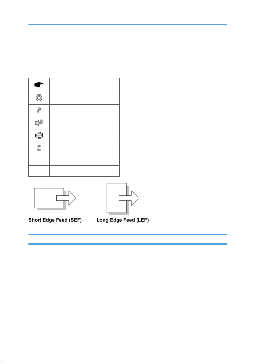
Symbols, Abbreviations and Trademarks
This manual uses several symbols and abbreviations. The meaning of those symbols and abbreviations
are as follows:
See or Refer to
Clip ring
Screw
Connector
Clamp
E-ring
SEF Short Edge Feed
LEF Long Edge Feed
Trademarks
Microsoft®, Windows®, and MS-DOS® are registered trademarks of Microsoft Corporation in the
United States and /or other countries.
PostScript® is a registered trademark of Adobe Systems, Incorporated.
PCL® is a registered trademark of Hewlett-Packard Company.
Ethernet® is a registered trademark of Xerox Corporation.
PowerPC® is a registered trademark of International Business Machines Corporation.
Other product names used herein are for identification purposes only and may be trademarks of their
respective companies. We disclaim any and all rights involved with those marks.
4

TABLE OF CONTENTS
Safety Notices.....................................................................................................................................................1
Important Safety Notices...............................................................................................................................1
Prevention of Physical Injury.................................................................................................................1
Health Safety Conditions......................................................................................................................1
Observance of Electrical Safety Standards.........................................................................................1
Safety and Ecological Notes for Disposal...........................................................................................1
Handling Toner......................................................................................................................................2
Laser Safety.....................................................................................................................................................2
Symbols, Abbreviations and Trademarks.........................................................................................................4
Trademarks.....................................................................................................................................................4
1. Product Information
Specifications....................................................................................................................................................11
Machine Overview..........................................................................................................................................12
Component Layout.......................................................................................................................................12
Paper Path....................................................................................................................................................13
Drive Layout..................................................................................................................................................14
Machine Configuration....................................................................................................................................15
2. Installation
Installation Requirements.................................................................................................................................17
Environment..................................................................................................................................................17
Machine Level..............................................................................................................................................18
Machine Space Requirement.....................................................................................................................18
Power Requirements....................................................................................................................................18
Installation Procedure..................................................................................................................................19
3. Preventive Maintenance
PM Intervals......................................................................................................................................................21
PM Parts........................................................................................................................................................21
Yield Counter................................................................................................................................................21
Counter Reset......................................................................................................................................22
4. Replacement and Adjustment
Before You Start...............................................................................................................................................23
Special Tools....................................................................................................................................................24
Exterior Covers.................................................................................................................................................25
5

Front Cover...................................................................................................................................................25
Left Cover......................................................................................................................................................26
Rear Cover...................................................................................................................................................29
Right Cover...................................................................................................................................................30
Top Cover.....................................................................................................................................................31
When installing the top cover............................................................................................................32
ADF....................................................................................................................................................................33
ADF Unit........................................................................................................................................................33
Original Tray................................................................................................................................................34
ADF Feed Unit..............................................................................................................................................34
ADF Separation Pad....................................................................................................................................35
ADF Front Cover .........................................................................................................................................35
ADF Rear Cover...........................................................................................................................................36
ADF Top Cover............................................................................................................................................36
ADF Motor....................................................................................................................................................37
Original Set Sensor......................................................................................................................................38
ADF Cover Open Sensor............................................................................................................................39
ADF Feed Sensor.........................................................................................................................................40
ADF Drive Board..........................................................................................................................................41
ARDF.................................................................................................................................................................42
ARDF Unit.....................................................................................................................................................42
Original Tray................................................................................................................................................43
ARDF Feed Unit............................................................................................................................................44
ARDF Separation Pad..................................................................................................................................44
ARDF Front Cover .......................................................................................................................................45
ARDF Rear Cover.........................................................................................................................................46
ARDF Top Cover..........................................................................................................................................47
ARDF Motor.................................................................................................................................................48
ARDF Cover Open Sensor..........................................................................................................................50
Original Set Sensor/Original Reverse Sensor..........................................................................................51
ARDF Feed Sensor.......................................................................................................................................54
ARDF Drive Board........................................................................................................................................55
Scanner Unit.....................................................................................................................................................57
6

Operation Panel...........................................................................................................................................58
Scanner Top Cover......................................................................................................................................58
Scanner Carriage Unit.................................................................................................................................59
Exposure Lamp.............................................................................................................................................61
When reinstalling the exposure lamp................................................................................................63
Lamp Stabilizer Board.................................................................................................................................63
Scanner Motor.............................................................................................................................................64
Laser Unit..........................................................................................................................................................66
Caution Decal Locations.............................................................................................................................66
Laser Unit......................................................................................................................................................66
Polygon Mirror Motor.................................................................................................................................67
Paper Feed and Exit.........................................................................................................................................69
Paper Feed Roller........................................................................................................................................69
After installing a new paper feed roller.............................................................................................69
Friction Pad...................................................................................................................................................70
Paper End Sensor.........................................................................................................................................70
By-pass Feed Roller.....................................................................................................................................70
By-Pass Feed Roller Friction Pad.................................................................................................................72
By-pass Feed Sensor...................................................................................................................................73
Paper Feed Clutch........................................................................................................................................73
Relay Clutch.................................................................................................................................................75
Registration Clutch.......................................................................................................................................75
Toner End Sensor.........................................................................................................................................75
Paper Exit Sensor.........................................................................................................................................76
Relay Sensor.................................................................................................................................................76
Inverter Sensor.............................................................................................................................................77
Registration Roller and Sensor....................................................................................................................77
Paper Transfer..................................................................................................................................................81
Transfer Roller..............................................................................................................................................81
After installing a new transfer roller...................................................................................................81
Fusing................................................................................................................................................................82
Fusing Unit....................................................................................................................................................82
Reinstallation........................................................................................................................................84
7

After installing a new fusing unit.........................................................................................................84
Thermostat....................................................................................................................................................85
Thermistor.....................................................................................................................................................85
Fusing Lamp..................................................................................................................................................86
When reinstall the fusing lamp...........................................................................................................87
Hot Roller......................................................................................................................................................88
Pressure Roller..............................................................................................................................................88
Hot Roller Stripper Pawls.............................................................................................................................89
Motors...............................................................................................................................................................90
Main Motor..................................................................................................................................................90
Duplex Motor (For M119)..........................................................................................................................90
Electrical Components.....................................................................................................................................92
Layout of PC Boards....................................................................................................................................92
USB Host Board..................................................................................................................................92
ECB (Engine Controller Board)..........................................................................................................93
EEPROM..............................................................................................................................................94
Controller Board.................................................................................................................................95
FCU......................................................................................................................................................95
PSU................................................................................................................................................................96
Charge Terminal Case..............................................................................................................................100
Others.............................................................................................................................................................101
Cooling Fan...............................................................................................................................................101
Speaker......................................................................................................................................................101
Quenching Lamp.......................................................................................................................................102
Image Adjustment..........................................................................................................................................103
Registration Adjustment.............................................................................................................................103
User Adjustment................................................................................................................................103
Service Adjustment...........................................................................................................................103
5. System Maintenance Reference
Service Program Mode.................................................................................................................................105
Overview....................................................................................................................................................105
Maintenance Mode Menu.......................................................................................................................105
Selecting an Item..............................................................................................................................105
8

Going into the Next Level/ Returning to the Previous Level..........................................................105
Exiting the Maintenance Mode Menu............................................................................................105
Menu List............................................................................................................................................105
Fax Service Test Menu..............................................................................................................................121
Entering the Fax Service Test Menu................................................................................................121
Selecting an Item..............................................................................................................................121
Going into the Next Level/ Returning to the Previous Level..........................................................121
Exiting the Maintenance Mode Menu............................................................................................122
Menu List............................................................................................................................................122
Configuration and Maintenance Page .......................................................................................................124
Overview....................................................................................................................................................124
To Print the Configuration Page/ Maintenance Page...................................................................124
Other Types of Reports.....................................................................................................................124
Total Counter.....................................................................................................................................125
Firmware Updating........................................................................................................................................126
Checking the Machine Firmware Version...............................................................................................126
Updating the Controller Firmware...........................................................................................................126
Procedure..........................................................................................................................................126
Updating the Engine Firmware.................................................................................................................128
Procedure..........................................................................................................................................128
Updating the Boot Loader Firmware.......................................................................................................129
Updating Failure........................................................................................................................................129
FW Update Tool Messages......................................................................................................................130
FW Update Tool Messages: Information........................................................................................130
FW Update Tool Messages: Error...................................................................................................132
6. Troubleshooting
Service Call Conditions.................................................................................................................................135
Summary....................................................................................................................................................135
Fusing related SCs............................................................................................................................135
Engine SC...................................................................................................................................................135
SC 2xx (Laser Optics Error).............................................................................................................135
SC 4xx (Image Transfer and Transfer Error)..................................................................................137
SC 5xx (Motor and Fusing Error)....................................................................................................137
9

SC 6xx (Communication and Other Error).....................................................................................141
Controller SC.............................................................................................................................................142
SC 8xx...............................................................................................................................................142
Image Problems.............................................................................................................................................143
Overview....................................................................................................................................................143
Test Page Printing......................................................................................................................................143
Test Page Print Procedure.................................................................................................................143
Test Pattern Printing....................................................................................................................................144
Test Pattern Print Procedure..............................................................................................................144
Dark lines in halftone areas at 75mm Intervals.......................................................................................145
Jam..................................................................................................................................................................146
Jam Sensor Layout.....................................................................................................................................146
Paper Jam..........................................................................................................................................146
Original Jam (AFD)...........................................................................................................................147
Original Jam (ARFD)........................................................................................................................147
Jam Message List.......................................................................................................................................148
Paper Jam..........................................................................................................................................148
Original Jam......................................................................................................................................149
Energy Save...................................................................................................................................................150
Energy Saver Modes................................................................................................................................150
Timer Settings....................................................................................................................................150
Return to Stand-by Mode.................................................................................................................151
Recommendation..............................................................................................................................151
Paper Save.....................................................................................................................................................152
Effectiveness of Duplex/Combine Function............................................................................................152
1. Duplex:..........................................................................................................................................152
2. Combine mode:............................................................................................................................152
3. Duplex + Combine:......................................................................................................................152
Total counter.....................................................................................................................................153
10

1. Product Information
Specifications
See "Appendices" for the following information:
• "General Specifications"
• "Printer"
• "Copier"
• "Scanner"
• "Fax"
• "Supported Paper Sizes"
11
1. Product Information
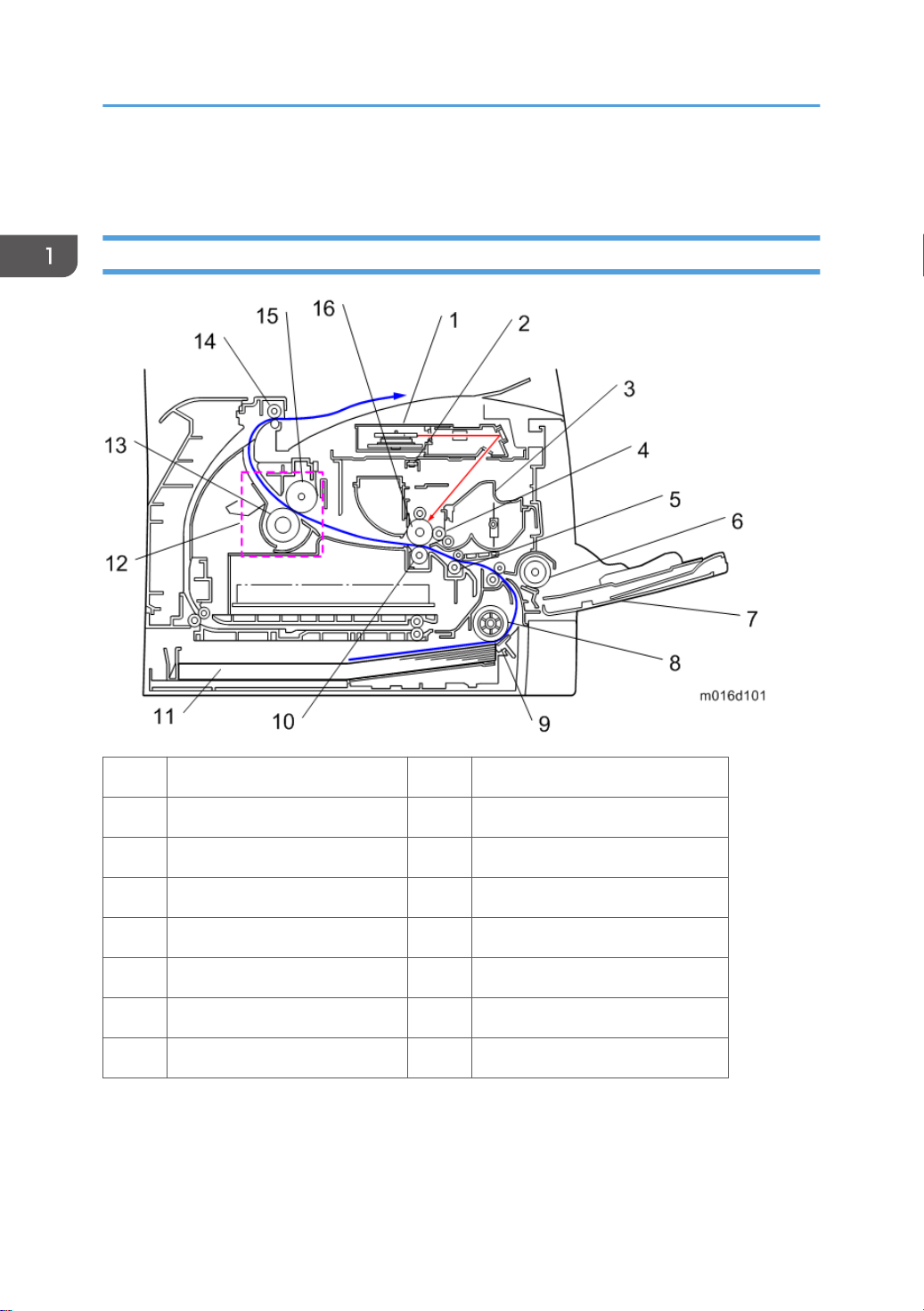
Machine Overview
Component Layout
12
1. Laser unit 9. Friction pad
2. Quenching lamp 10. Transfer roller
3. Cartridge (AIO-type) 11. Paper Tray
4. Development roller 12. Fusing Unit
5. Registration roller 13. Pressure Roller
6. By-pass feed roller 14. Paper exit roller
7. By-pass feed tray 15. Hot Roller
8. Paper feed roller 16. Drum

Paper Path
Machine Overview
[A] Duplex section (For M119)
[B] Standard paper tray unit
[C] Optional paper tray unit
13
1. Product Information
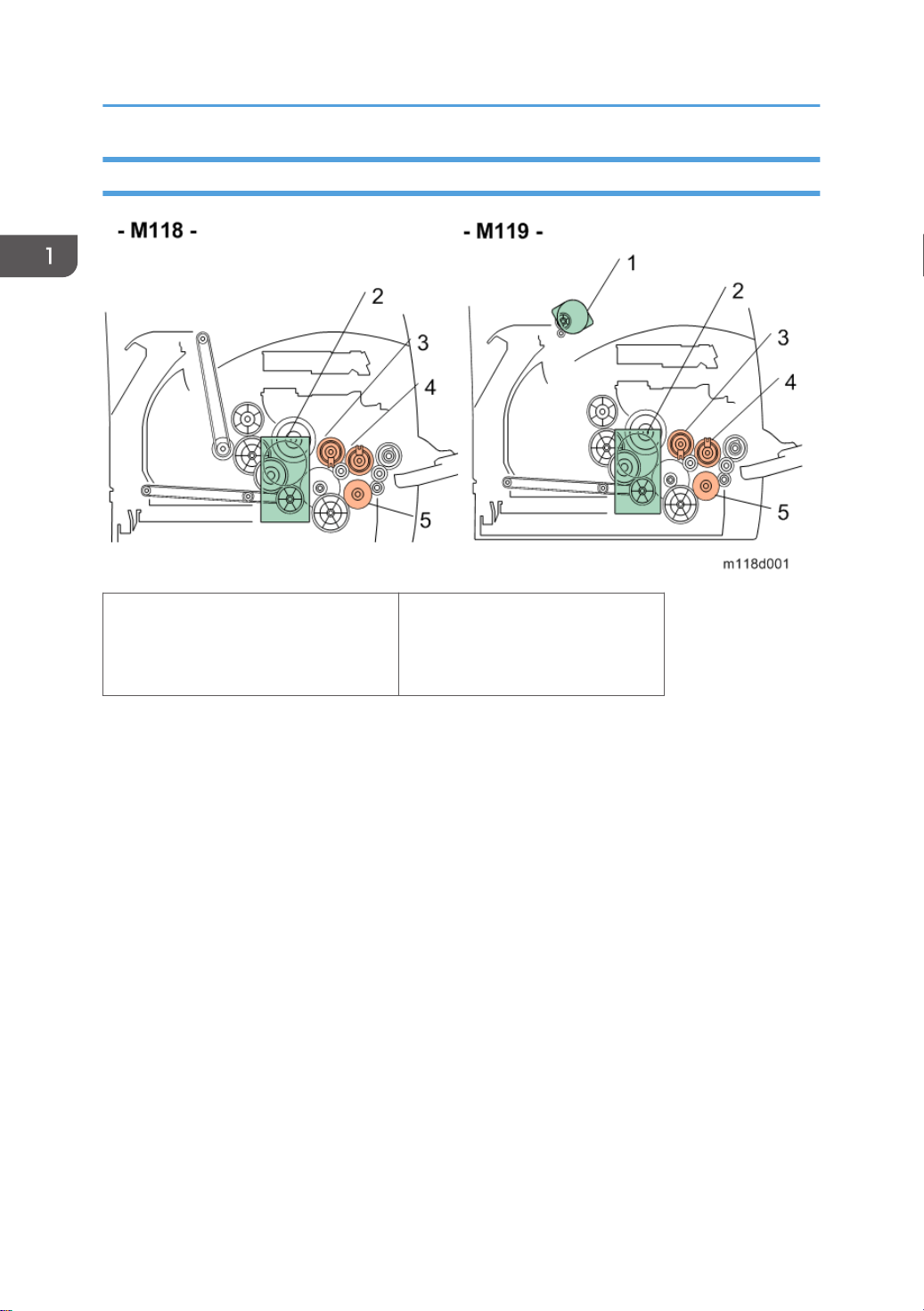
Drive Layout
1. Duplex Motor
2. Main Motor
3. Registration Clutch
4. Replay Clutch
5. Paper Feed Clutch
14
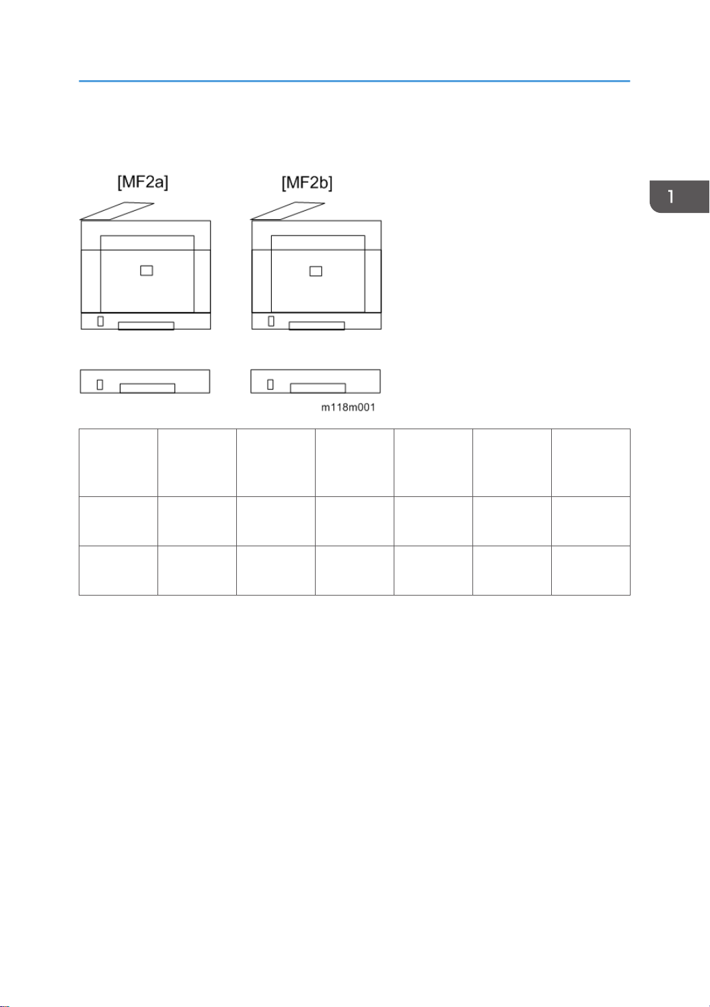
Machine Configuration
Machine Configuration
Models Duplex Unit
RN-MF2a
(M118)
RN-MF2b
(M119)
NA: Not Available
Optional
Memory
NA NA 250x1 Yes Yes Yes
Auto NA 250x1 Yes Yes Yes
Optional
Tray
(M355)
PCL, PS Fax USB Host
15

1. Product Information
16
2. Installation
Installation Requirements
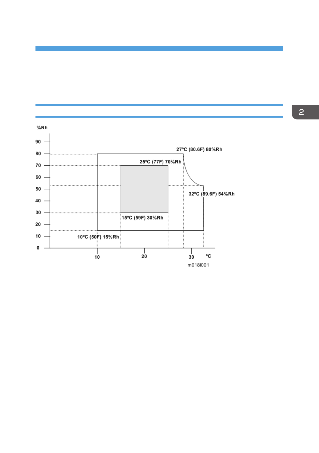
Environment
1. Temperature Rage: 10°C to 32°C (50°F to 89.6°F)
2. Humidity Range: 15% to 80% RH
3. Ambient Illumination: Less than 2,000 lux (do not expose to direct sunlight)
4. Ventilation: 3 times/hr/person
5. Do not put the machine in areas with sudden temperature changes. This includes:
• Areas directly exposed to cool air from air conditioning
• Areas directly exposed to heat from a heating system.
6. Do not put the machine in areas exposed to corrosive gas.
7. Do not install the machine at locations over 2,000 m (6,562 ft.) above sea level.
8. Put the machine on a strong, level base. (Tilting towards any side must be no more than 3 mm.)
9. Do not put the machine in areas with strong vibrations.
17
2. Installation
Machine Level
Front to back: Within 5 mm (0.2") of level
Right to left: Within 5 mm (0.2") of level
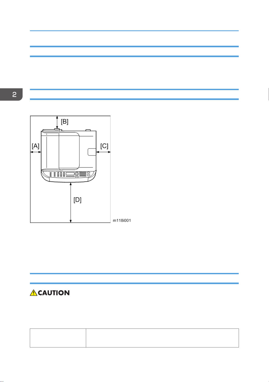
Machine Space Requirement
Put the machine near a power source with these clearances:
A: Over 10 cm (4")
B: Over 20 cm (7.9")
C: Over 20 cm (7.9")
D: Over 70 cm (27.6")
Power Requirements
• Make sure that the plug is tightly in the outlet.
• Avoid multi-wiring.
• Make sure that you ground the machine.
Input voltage level
18
NA: 120 V, TW: 110 V, 60 Hz: Less than 10 A
EU/ Asia/ CHN: 220 V to 240 V, 50 Hz/60 Hz: Less than 5 A

Permitted voltage fluctuation: 10%
Do not set anything on the power cord.
Installation Procedure
Refer to the "User Guide".
Installation Requirements
19

2. Installation
20
3. Preventive Maintenance
PM Intervals
PM Parts
There are no PM parts in this machine.
• Other than the three Yield Parts listed below, there are essentially no PM parts required for this
product.
• These three items will need to be replaced in cases where their yield is near, however, given the
ACV (Average Copy Volume) for this product, these "yield parts*1 " are expected to outlast the
working life of the machine.
*1 "Yield Parts": Parts whose expected yield is longer than the machine lifetime when taking into
consideration the machine's ACV.
Description Expected Yield Q'ty/unit
Paper Feed Roller 120 K prints 1
Transfer Roller 120 K prints 1
Fusing Unit 120 K prints 1
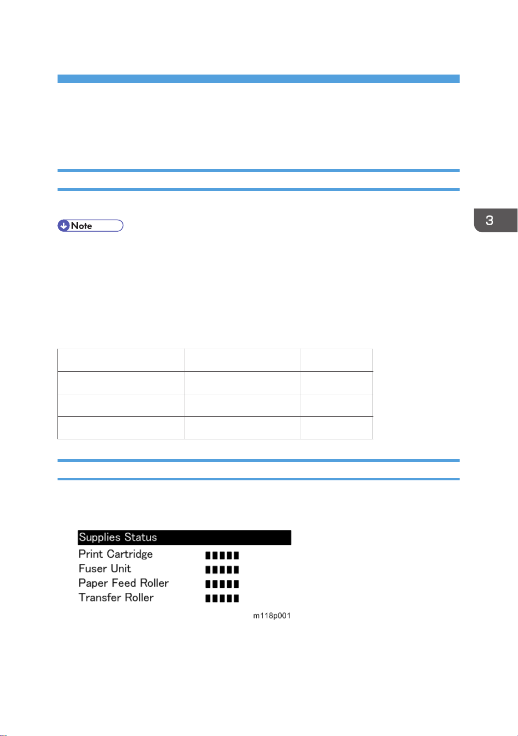
Yield Counter
Yield counters for each yield part can be checked by the following methods.
Configuration Page in the “Print List/Report” menu
21
3. Preventive Maintenance
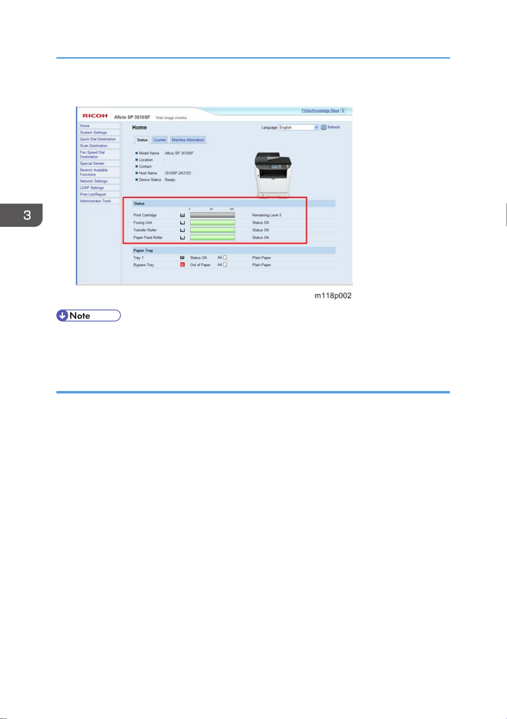
Web Image Monitor
• The machine displays "Fuser life end notice", "Transfer roller life end notice" or "Life End of Paper
Feed Roller Unit" when one of these counters reaches each yield.
Counter Reset
The process below shows how to reset the yield counters.
1. Enter the "Maintenance mode".
2. Select "Engine Maintenance", and then press "OK" key.
3. Select "Reset Fuser Unit", "Reset Transfer Unit" or "Reset Paper Feed Rol Life" and then press "OK"
key.
4. Press the left key “Execute” of the “Selection keys”.
5. Exit the "Maintenance mode".
22

4. Replacement and Adjustment
Before You Start
• If there are printer jobs in the machine, print out all jobs in the printer buffer.
• Turn off the main power switch and unplug the machine before you do the procedures in this
section.
23

4. Replacement and Adjustment
Special Tools
• PC: Windows XP/Vista/7, Windows Server 2003/2003 R2, 2008/2008 R2
• USB or network cable
• A computer is necessary to update the firmware.
24
Exterior Covers
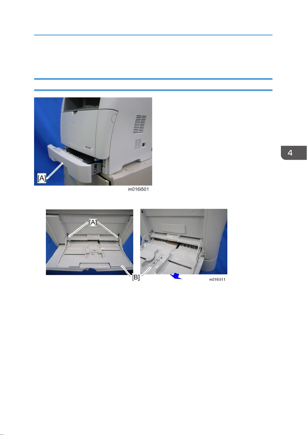
Front Cover
1. Pull out the standard paper tray [A].
Exterior Covers
2. Remove two tabs [A].
3. Pull out the bypass tray [B].
25
4. Replacement and Adjustment
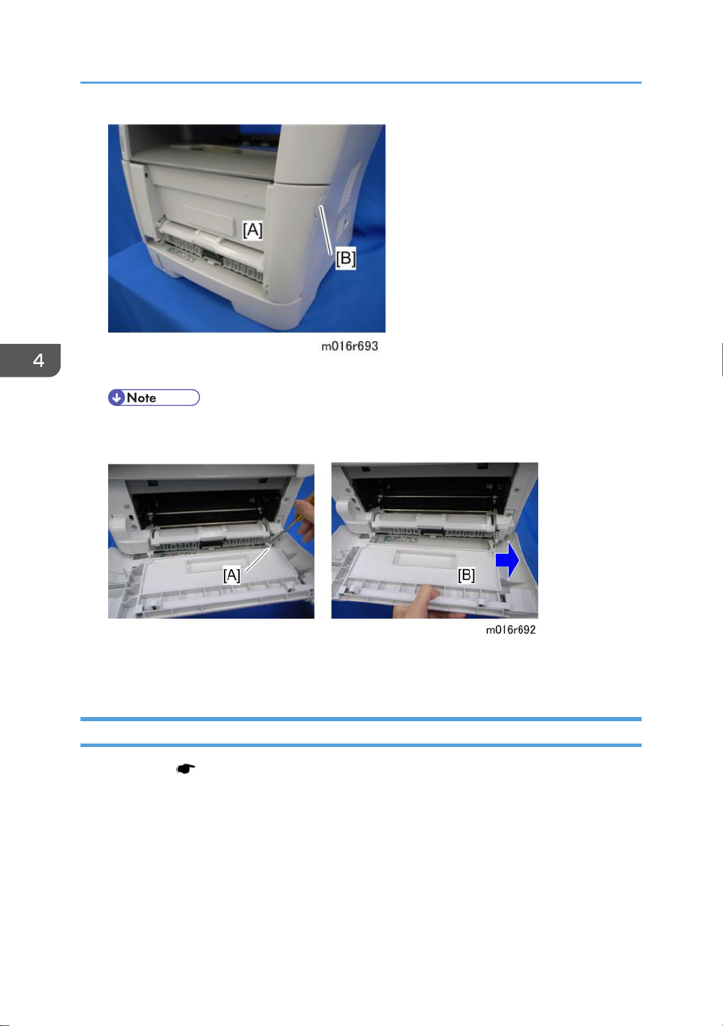
4. Open the front cover [A].
• To open the front cover, push the cover release button [B] and (carefully) pull the cover
forward and open (it hinges downward).
26
5. Push the right hinge [A] to release.
6. Front cover [B]
Left Cover
1. Front cover ( p.25)
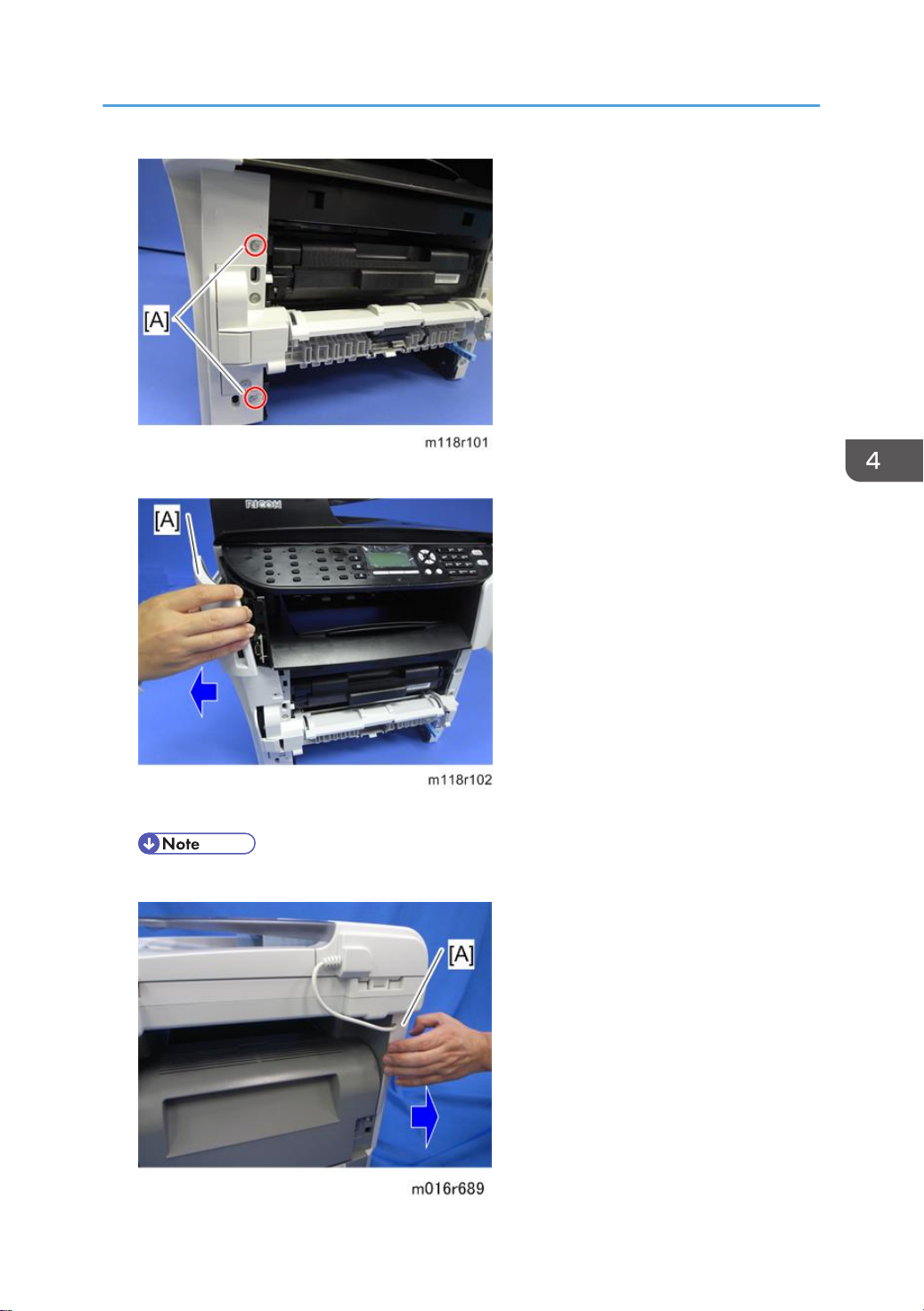
2. Remove two screws [A] on the front side of the left cover.
Exterior Covers
3. Pull the front upper part [A] of the left cover to release the hooks.
• Located outside of the cover has marks indicating the position of the hook.
27
4. Replacement and Adjustment
4. Pull the rear upper part [A] of the left cover to release the hooks.
• Located outside of the cover has marks indicating the position of the hook.
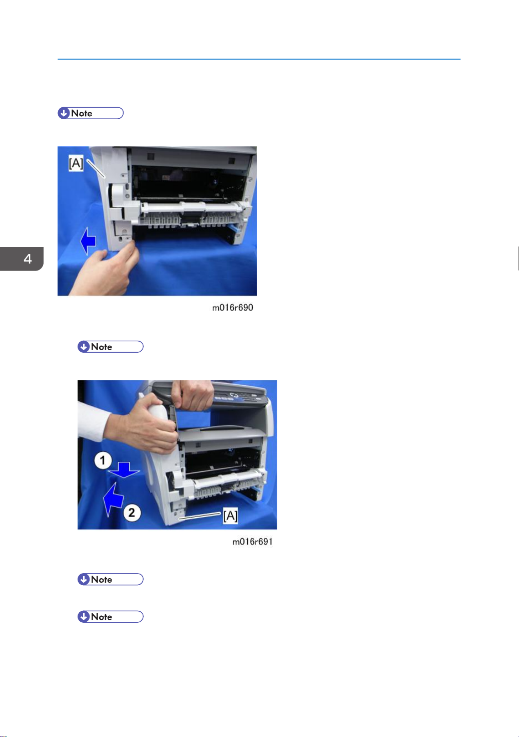
1. Pull the front bottom part of the left cover [A] to release the hooks.
• Located outside of the cover has marks indicating the position of the hook.
2. Remove the Left cover [A].
• Located outside of the cover has marks indicating the position of the hook.
• There are many hooks and tabs inside the left cover. Before removing the left cover, see the
images below.
28
 Loading...