


Charge pump for White LED
RN5T649
Development Specifications
Rev. 1.2
2009/05/19
RICOH COMPANY, LTD.
Electronic Devices Company
This specification is subject to change without notice.

RN5T649 CHARGE PUMP FOR WHITE LED
Table of Contents
1.
Outline........................................................................................................................................................................3
2. Feature .......................................................................................................................................................................3
3. Ordering Information ...............................................................................................................................................3
4. Pin Configuration......................................................................................................................................................4
5. Typical Application Circuit ......................................................................................................................................5
6. Pin Description ..........................................................................................................................................................6
7. Functional Blocks......................................................................................................................................................7
7.1 Single Wire Serial Pulse I/F of LDO1/2 .............................................................................................................7
7.2 LDO1/2 Electrical Characteristics ......................................................................................................................8
7.3 Charge Pump.......................................................................................................................................................9
7.3.1 Block Diagram ..........................................................................................................................................9
7.3.2 Backlight LED......................................................................................................................................... 10
7.3.3 Protection Circuit .................................................................................................................................... 11
7.3.4 Unused DIN_ pin ....................................................................................................................................11
7.3.5 Soft-start.................................................................................................................................................. 11
7.3.6 Luminance Control.................................................................................................................................. 12
7.3.7 Single Wire Serial Pulse I/F of LED Driver............................................................................................ 13
7.3.8 Charge Pump Electrical Characteristics .................................................................................................. 14
7.4 UVLO (Under Voltage Lock Out)....................................................................................................................15
7.5 Thermal Shutdown Circuit................................................................................................................................16
7.5.1 Thermal Shutdown Electrical Characteristics .........................................................................................16
8. Electrical Characteristics........................................................................................................................................17
8.1 Absolute Maximum Ratings .............................................................................................................................17
8.2 Recommendation of Operation Conditions.......................................................................................................17
8.3 DC Characteristics ............................................................................................................................................17
9. Package Information...............................................................................................................................................18
©2009 Rev. 1.2 Page 2
CHARGE PUMP FOR WHITE LED RN5T649
1. Outline
RN5T649 contains a constant frequency charge pump, which is optimized for White LED application. Output
enable/disable, LEDs current and LDOs ON/OFF are individually controllable through single wire serial pulse I/F.
2. Feature
z White LED Charge Pump
9 Current capability: Up to 92mA
9 1x/1.33x/1.5x switchable charge pump mode
9 Power up four LEDs for backlight: Up to 23mA/LED
9 Luminance control with 32steps from 0.25mA to 23mA
9 Soft-start
z Power Supply Function
9 LDO (150mA) × 2 (ON/OFF control through single wire serial pulse I/F)
9 LDO output voltage is settable in 0.05V step in range of 1.2V to 3.3V
9 Over current protection (All Regulators) and thermal shutdown
z Others
9 UVLO
9 Short-circuit Protection
z Package
9 20pin QFN package (Body size: 3.0 x 3.0 x 0.75mm, Pin pitch 0.4mm)
z Process
9 CMOS process
3. Ordering Information
RN5T649
LDO Output voltage : LDOUT1 / LDOUT2
U: 1.80V / 2.80V
V: 1.50V / 2.80V
©2009 Rev. 1.2 Page 3
CHARGE PUMP FOR WHITE LED RN5T649
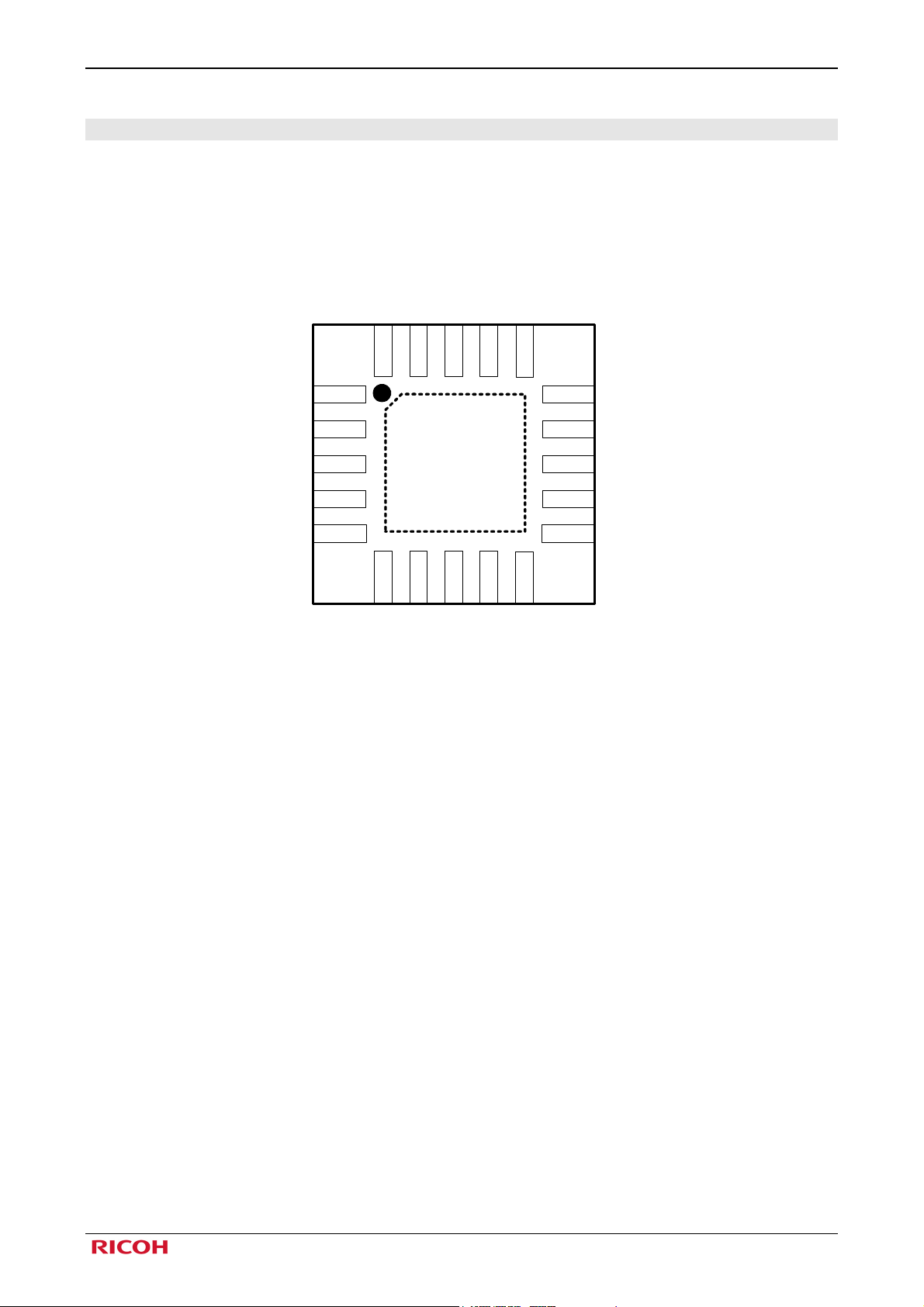
4. Pin Configuration
LDOCTL
20
DIN1
19
DIN2
18
NC
GNDCOM
17
16
LEDCTL
C2M
C3P
VOUT
C1P
1
2
3
TOP VIEW
4
5
6
7
C2P
C1M
9
8
C3M
VCCCP
Fig 4-1 Pin Configuration
10
GNDCP
15
14
13
12
11
DIN3
DIN4
LDOUT2
VCCCOM
LDOUT1
©2009 Rev. 1.2 Page 4
CHARGE PUMP FOR WHITE LED RN5T649
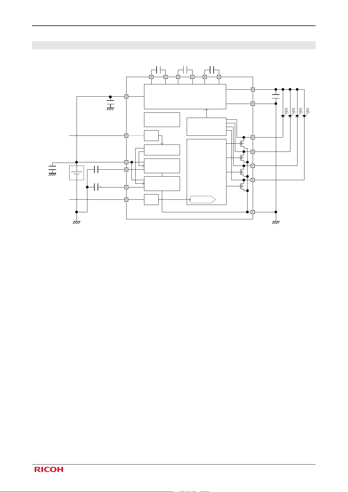
5. Typical Application Circuit
VCCCP
4.7uF
GND
Controlled with
GPIO of CPU
4.7uF
GND
Controlled with
GPIO of CPU
Li-ion
Battery
GND
LDOCTL
VCCCOM
1uF
LDOUT2
1uF
LEDCTL
NR: Noise reduction
1uF 1uF 1uF
Charge Pump
@92mA (1x,1.33x,1.5x)
Thermal
Shutdown
NR
Logic
LDO1LDOUT1
LDO2
NR
RN5T649
Feed Back
Adjust Voltage
Current Driver
5bit DAC
VOUT
2.2µF
GNDCP
DIN1
@23mA
DIN2
@23mA
DIN3
@23mA
DIN4
@23mA
GNDCOM
GND
Fig 5-1 Typical Application Circuit
©2009 Rev. 1.2 Page 5
RN5T649 CHARGE PUMP FOR WHITE LED
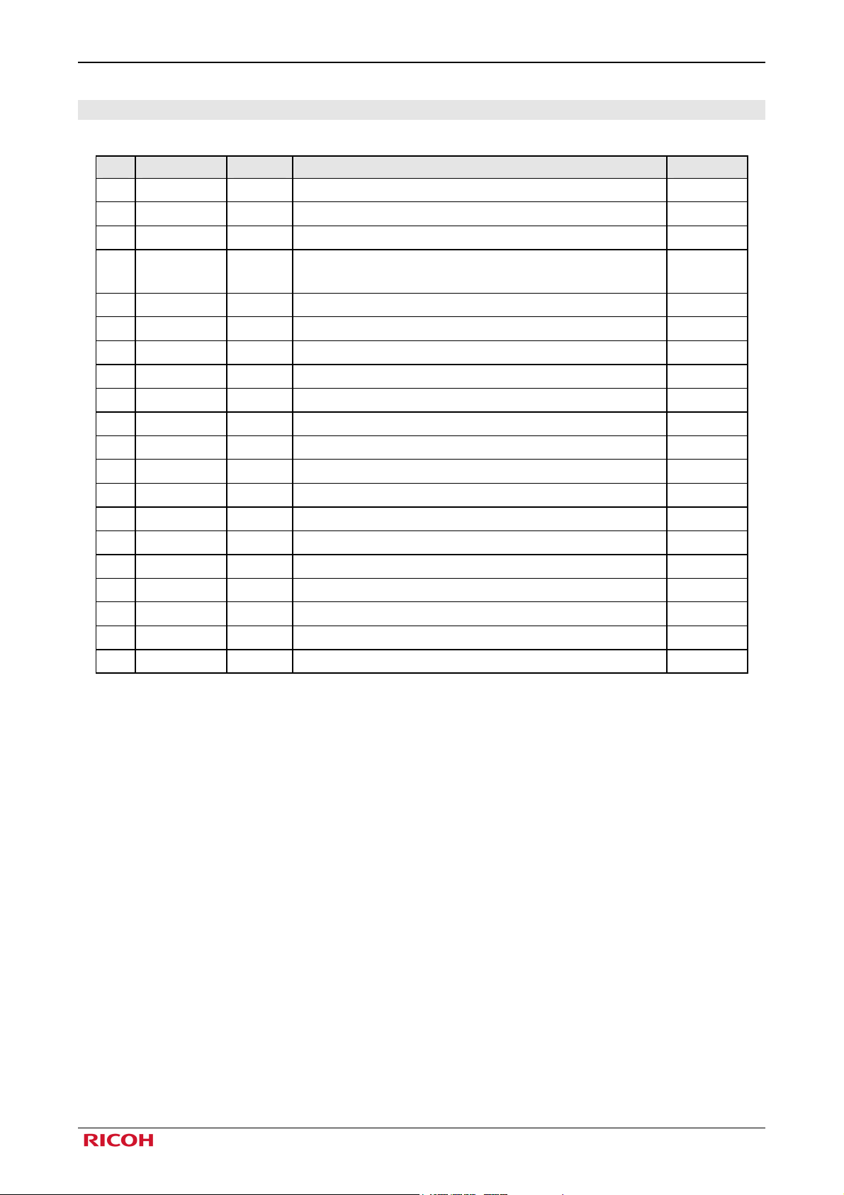
6. Pin Description
No. Name I/O Description Notes
LEDCTL
1
2
3
4
5
6
7
8 VCCCP PWR Power supply for charge pump
9
10
11
12
13
14
15
16
17
18
19
20
C2M
C3P
VOUT
C1P
C2P
C1M
C3M
GNDCP
LDOUT1
VCCCOM
LDOUT2
DIN4
DIN3
NC
GNDCOM
DIN2
DIN1
LDOCTL
I ON/OFF control and Current setting of LED driver
- Charge pump boost capacitor connection
- Charge pump boost capacitor connection
O
GND Ground for charge pump
O Output of LDO1.
PWR Power supply for LDO, UVLO, Logic block and TSHUT.
O Output of LDO2
O LED driver current control output
O LED driver current control output
GND Ground for LDO, UVLO, Logic block and TSHUT.
O LED driver current control output
O LED driver current control output
LED driver voltage output.
VOUT is high impedance during shutdown.
- Charge pump boost capacitor connection
- Charge pump boost capacitor connection
- Charge pump boost capacitor connection
- Charge pump boost capacitor connection
- No connection *1
I LDO1/2 ON/OFF control input
Note*1: NC pin should be connected to GND or open.
Table 6-1 Pin Description
©2009 Rev. 1.2 Page 6
 Loading...