


Step-down DC/DC with LDOs
RN5T562
Development Specifications
Rev.1.5
2009/05/14
RICOH COMPANY, LTD.
Electronic Devices Company
This specification is subject to change without notice.

RN5T562 Step-down DC/DC with LDOs
Table of Contents
1. Outline........................................................................................................................................... 3
2. Feature........................................................................................................................................... 3
3. Application.................................................................................................................................... 3
4. Ordering Information .................................................................................................................... 3
5. Block Diagram .............................................................................................................................. 4
6. Pin Configuration.......................................................................................................................... 4
7. Pin Description.............................................................................................................................. 5
8. Electrical Characteristics............................................................................................................... 6
8.1 Absolute Maximum Ratings .................................................................................................................... 6
8.2 Recommended Operating Conditions........................................................................................................ 6
8.3 Step-down DC/DC Converter Electrical Characteristics ............................................................................. 7
8.4 LDO1 Electrical Characteristics ............................................................................................................... 8
8.5 LDO2 Electrical Characteristics ............................................................................................................... 9
8.6 UVLO (Under Voltage Lock Out) Electrical Characteristics..................................................................... 10
8.7 Thermal Shutdown Circuit Electrical Characteristics ............................................................................... 10
8.8 DC Electrical Characteristics ................................................................................................................. 11
9. ON/OFF Control of LDOs and DC/DC ...................................................................................... 11
10. Step-down DC/DC Converter .................................................................................................. 12
10.1 Step-down DC/DC Converter Output Voltage Setting.............................................................................. 12
11. Typical Application and Application Hints ............................................................................. 13
12. Appendix.................................................................................................................................. 14
12.1 Reference Data of Step-down DC/DC Converter ..................................................................................... 14
13. Package Information ................................................................................................................ 16
©2009 Rev.1.5 Page 2
RN5T562 Step-down DC/DC with LDOs
1. Outline
RN5T562 integrates CMOS-based step-down DC/DC converter and two low dropout regulators (LDOs) with low
supply current. A low ripple, high efficiency step-down DC/DC converter can be easily composed of this IC with
some external components such as inductor, capacitors and resistor. The self-oscillation frequency is up to 2MHz
and it allows DCDC to use small inductor and capacitor.
Output enable/disable of regulators is individually controllable through external pins. In addition, this IC has the
under voltage lockout function (UVLO), which powers off all the regulators with 2.20V (Typ.) UVLO threshold.
Also, RN5T562 has Thermal shutdown circuit which turns off all the regulators in the overheated state.
2. Feature
• Range of Input Voltage .............. 3.1V ~ 4.5V (DC/DC), 1.746V(1.8V-3.0%) ~ 4.5V (LDOs)
• Built-in Soft-start Function for DCDC
• Maximum Output Current.......... 500mA (DC/DC), 200mA (LDOs)
• Accuracy Output Voltage .......... ±3.0% (LDOs Output)
• Output Voltage (LDO1) ............ Settable in 0.05V step in range of 1.2V to 3.3V
• Output Voltage (LDO2) ............ Settable in 0.05V step in range of 1.2V to 3.3V
• Output Voltage (DC/DC) .......... Setting external resistance ratio in the range of 0.9V to 2.0V
• Thermal Shutdown Circuit
• UVLO
• Package ..................................... QFN 16pins, 3mm×3mm, t=0.8mm
• Process ...................................... CMOS
3. Application
• Power source for DMB.
• Power source for battery-powered equipment.
4. Ordering Information
RN5T562-XXXYYY
XXX : LDO1 Output Voltage.
YYY : LDO2 Output Voltage.
For example.
RN5T562-150180 : LDO1=1.50V, LDO2=1.80V.
©2009 Rev.1.5 Page 3
RN5T562 Step-down DC/DC with LDOs
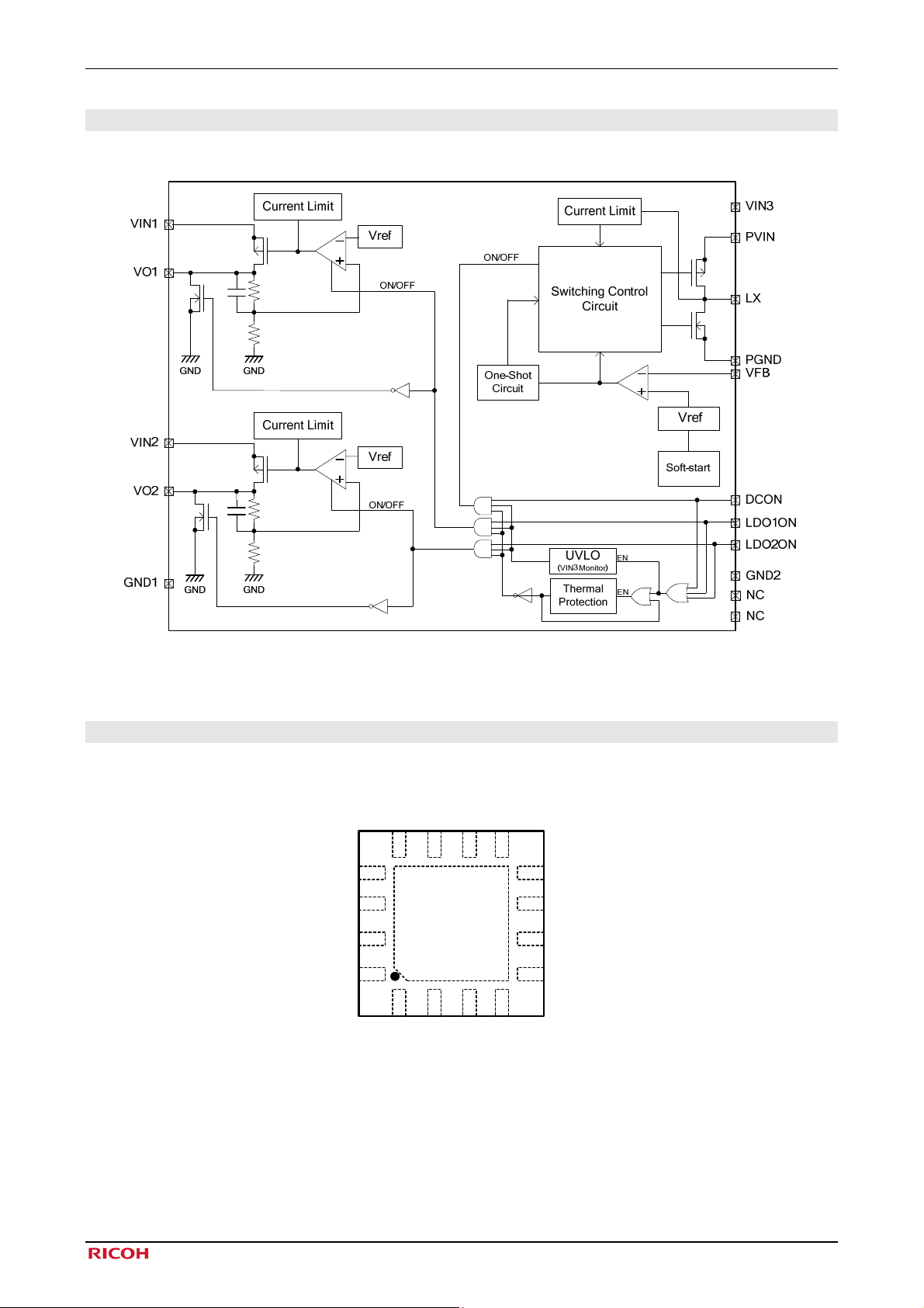
5. Block Diagram
The block diagram of the device is shown below.
6. Pin Configuration
QFN 16pins, 3mm×3mm, t=0.8mm
GND2
VFB
NC
NC
Fig 5-1 Block Diagram
LX
11
TOP
VIEW
2
VIN1
PGND
10
3
VIN2
PVIN
12
13
14
15
16
1
VO1
DCON
9
8
7
6
5
4
VO2
LDO2ON
LDO1ON
VIN3
GND1
Fig 6-1 Pin Configuration
©2009 Rev.1.5 Page 4
RN5T562 Step-down DC/DC with LDOs
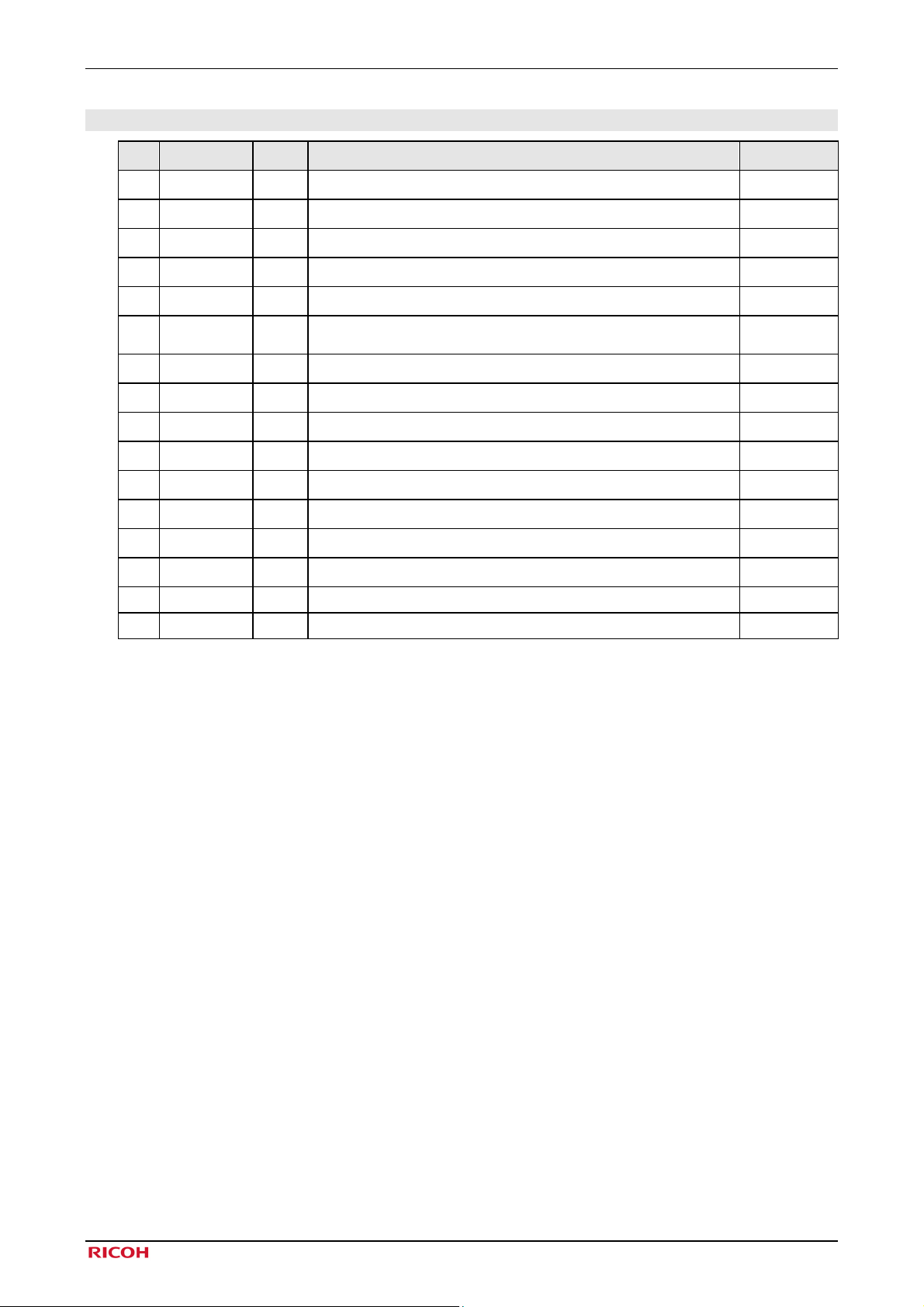
7. Pin Description
No. Name I/O
1 VO1
2 VIN1
3 VIN2
4 VO2
5 GND1
6
7 LDO1ON
8 LDO2ON
9 DCON
10 PGND
11
12
13 GND2
14 VFB
15 NC - Non-connect. Connect to GND.
16 NC - Non-connect. Connect to GND.
VIN3
LX
PVIN
PWR
PWR
GND
PWR
GND
PWR
GND
Output voltage of LDO1.
O
Power supply for LDO1.
Power supply for LDO2.
Output voltage of LDO2.
O
GND for LDO block, UVLO, and TSHUT.
Power supply for DC/DC converter control block, UVLO, and
TSHUT.
Input of LDO1 for ON/OFF.
I
Input of LDO2 for ON/OFF.
I
DC/DC ON/OFF control.
I
GND for DC/DC converter.
DC/DC converter switch output.
O
Power supply for DC/DC converter driver.
GND for DC/DC converter control block.
Output voltage feedback input of DCDC converter.
I
Function Notes
Table 7-1 Pin Description
©2009 Rev.1.5 Page 5

RN5T562 Step-down DC/DC with LDOs
8. Electrical Characteristics
8.1 Absolute Maximum Ratings
The operation exceeding “Absolute Maximum Ratings” below may cause permanent damage to the device.
The operation of the device within the stated ratings below is not guaranteed.
Symbol Parameter Condition Rated Value Units
VIN Power Input Pin Voltage VIN1~3, PVIN pin -0.3~6.0 V
VLX LX Pin Voltage LX pin -0.3~4.5 V
V1 / V2 VO1, VO2 Pin Voltage VO1, VO2 pin -0.3~4.5 V
V
Input Voltage Range
PIN
PD
T
Storage Temperature - -55~+125 ℃
stg
Package
Allowable Dissipation
Note*1: Derate 17.27 [mW/℃] above +70℃.
Table 8-1 Absolute Maximum Ratings
DCON,
LDO1ON, LDO2ON
Mounted on Board,
=70℃
T
a
-0.3~VIN3+0.3 V
*1
950
mW
8.2 Recommended Operating Conditions
Symbol Parameter Condition Min Typ Max Units
VIN1 pin
- Power Supply Voltage1
VOUT1+0.3V<1.746V
VIN1 pin
VOUT1+0.3V≧1.746
VIN2 pin
- Power Supply Voltage2
VOUT2+0.3V<1.746V
VIN2 pin
VOUT2+0.3V≧1.746
- Power Supply Voltage3 VIN3 pin 3.1 4.5 V
-
Ta
DC/DC
Power Supply Voltage
Temperature
of Operation
PVIN pin 3.1 4.5 V
- -40 +85 ℃
Table 8-2 Recommendation of Operation Conditions
1.746
(1.8-3%)
VOUT1
+0.3
1.746
(1.8-3%)
VOUT2
+0.3
4.5
V
4.5 V
4.5
V
4.5 V
©2009 Rev.1.5 Page 6

RN5T562 Step-down DC/DC with LDOs
8.3 Step-down DC/DC Converter Electrical Characteristics
Operating Conditions (unless otherwise specified) VIN1, VIN2, VIN3, PVIN = 3.6V, Ta = 25℃ L1=2.2μH, C
OUT
=4.7μF
Symbol Parameter Condition Min Typ Max Units
- Input Voltage Range VIN3, PVIN pin 3.1 4.5 V
DVOUT Output Voltage Range - 0.9 2.0 V
DIOUT Output current VIN3=PVIN=3.1~4.5V 500 mA
DISS
Consumption
Current
DIOFF Standby Current
DILIM
Limit detection
Current
VIN3=PVIN=VFB=3.6V
DIOUT=0mA, no switching
VIN3=PVIN=4.5V
OFF state
- 800 mA
70 μA
1 μA
VFB FB Voltage - -1.5% 0.608 +1.5% V
ΔVFB
ΔVIN
ΔVFB
ΔT
*2
t
r
T
ONmin
FB Line Regulation
FB Voltage
Temperature
Coefficient
Soft-start Time - 120 μs
Minimum-On-Time - 120 ns
VIN3=PVIN=3.1~4.5V
DIOUT=DIOUTmax / 2
7 mV
-40℃≦Ta≦+85℃ ±100 ppm/℃
Table 8-3 Step-down DC/DC Converter Electrical Characteristics
Note*: Load Regulation, which is determined by DC resistance (DCR) on inductor, is given by:
Load Regulation (Typ) = DCR (Ω)×DIOUT (A).
Note*1: When all regulators are off, Soft-start time will be added up with UVLO output delay time for releasing.
t
(Typ)= 120μs + 10μs(UVLO output delay time for releasing).
r
©2009 Rev.1.5 Page 7

RN5T562 Step-down DC/DC with LDOs
8.4 LDO1 Electrical Characteristics
Operating Conditions (unless otherwise specified) VIN1, VIN2, VIN3, PVIN = 3.6V, C
= 2.2μF, Ta = 25℃
OUT1
Symbol Parameter Condition Min Typ Max Units
- Input Voltage Range VIN1 pin
VOUT1*1
Output Voltage
Range
- 1.2 3.3 V
1.746
(1.8-3%)
4.5 V
IOUT1 Output Current - 200 mA
VIN1=VOUT1+0.3V
& IOUT1=IOUT1max,
VIN1=4.5V
& IOUT1=50μA
VIN1=1.746V
& IOUT1=IOUT1max,
VIN1=4.5V
&
-3 +3 %
&
VACC1
VOUT1+0.3V
≧1.746
Output Voltage
Accuracy
VOUT1+0.3V
<1.746V
& IOUT1=50μA
ISHT1 Short Current VO1=0V 120 mA
VOUT1+0.3V≦VIN1
≦4.5V,
IOUT1=IOUT1max /2
1.746V≦VIN1≦4.5V,
IOUT1=IOUT1max /2
10 mV
ΔVOUT1
ΔVIN
Line Regulation
VOUT1+0.3V
≧1.746
VOUT1+0.3V
<1.746V
ΔVOUT1
ΔIOUT1
ΔVOUT1
ΔT
a
Load Regulation
Output Voltage
Temperature
Coefficient
50μA<IOUT1<IOUT1max
VIN1=3.6V
-40℃≦T
30 mV
≦85℃ +100 ppm/℃
a
RR1 Ripple Rejection f=1kHz, IOUT1=IOUT1max / 2 60 dB
EN1 Output Noise (RMS)
BW=100Hz-100kHz
IOUT1=IOUT1max / 2
50 μVrms
ISS1 Supply Current IOUT1=0mA 70 μA
IOFF1 Standby Current IOUT1=0mA 1 μA
*2
C
Bypass Capacitor 0μA<IOUT1<200mA 2.2 μF
OUT1
*3
t
Rising Time
r1
tf1 Falling Time
IOUT1=0mA
VO1>VOUT1×90%
IOUT1=0mA
VO1<0.5V
10 μs
500 μs
Table 8-4 LDO1 Electrical Characteristics
Note*1: The output voltage will be fixed (with 0.05V step) by trimming at shipment.
Note*2: Bypass capacitor: 2.2μF, in the mounted state.
For optimized phase compensation, the bypass capacitor must be ceramic type.
Note*3: When all regulators are off, the rising time will be added up with UVLO output delay time for releasing.
t
(Typ)= 10μs + 10μs(UVLO output delay time for releasing).
r1
©2009 Rev.1.5 Page 8

RN5T562 Step-down DC/DC with LDOs
8.5 LDO2 Electrical Characteristics
Operating Conditions (unless otherwise specified) VIN1, VIN2, VIN3, PVIN = 3.6V, C
= 2.2μF, Ta = 25℃
OUT2
Symbol Parameter Condition Min Typ Max Units
- Input Voltage Range VIN2 pin
VOUT2*1
Output Voltage
Range
- 1.2 3.3 V
1.746
(1.8-3%)
4.5 V
IOUT2 Output Current - 200 mA
VIN2=VOUT2+0.3V
& IOUT2=IOUT2max,
&
VIN2=4.5V
& IOUT2=50μA
VIN2=1.746V
& IOUT2=IOUT2max,
&
VIN2=4.5V
-3 +3 %
VACC2
VOUT2+0.3V
≧1.746
Output Voltage
Accuracy
VOUT2+0.3V
<1.746V
& IOUT2=50μA
ISHT2 Short Current VO2=0V 120 mA
VOUT2+0.3V≦VIN2
≦4.5V,
IOUT2=IOUT2max /2
1.746V≦VIN2≦4.5V,
IOUT2=IOUT2max /2
10 mV
ΔVOUT2
ΔVIN
Line Regulation
VOUT2+0.3V
≧1.746
VOUT2+0.3V
<1.746V
ΔVOUT2
ΔIOUT2
ΔVOUT2
ΔT
Load Regulation 50μA<IOUT2<IOUT2max 30 mV
Output Voltage
a
Temperature
Coefficient
-40℃≦T
≦85℃ +100 ppm/℃
a
RR2 Ripple Rejection f=1kHz, IOUT2= IOUT2max / 2 60 dB
EN2 Output Noise (RMS)
BW=100Hz-100kHz
IOUT2= IOUT2max / 2
50 μVrms
ISS2 Supply Current IOUT2=0mA 70 μA
IOFF2 Standby Current IOUT2=0mA 1 μA
*2
C
Bypass Capacitor 0μA<IOUT2<200mA 2.2 μF
OUT2
*3
t
Rising Time
r2
tf2 Falling Time
IOUT2=0mA
VO2>VOUT2×90%
IOUT2=0mA
VO2<0.5V
10 μs
500 μs
Table 8-5
Table 8-6 LDO2 Electrical Characteristics
Note*1: The output voltage will be fixed (in 0.05V step) by trimming at shipment.
Note*2: Bypass capacitor: 2.2μF, in the mounted state.
For optimized phase compensation, the bypass capacitor must be ceramic type.
Note*3: When all regulators are off, the rising time will be added up with UVLO output delay time for releasing.
t
(Typ)= 10μs + 10μs(UVLO output delay time for releasing).
r2
©2009 Rev.1.5 Page 9

RN5T562 Step-down DC/DC with LDOs
8.6 UVLO (Under Voltage Lock Out) Electrical Characteristics
Operating Conditions (unless otherwise specified) Ta = 25℃
Symbol Parameter Condition Min Typ Max Units
V
Under voltage lock out threshold VCCVIN rising 2.25 V
Release
V
Under voltage lock out threshold VCCVIN falling 2.05 2.20 2.35 V
Detect
V
UVLO Hysteresis - 50 mV
HYS
Table 8-7 UVLO Electrical Characteristics
8.7 Thermal Shutdown Circuit Electrical Characteristics
Operating Conditions (unless otherwise specified) VIN1, VIN2, VIN3, PVIN = 3.6V
Symbol Parameter Condition Min Typ Max Units
T
DET
Detected
Temperature
- 140 ℃
T
Return Temperature - 110 ℃
RET
Table 8-8 Thermal Shutdown Circuit Electrical Characteristics
©2009 Rev.1.5 Page 10

RN5T562 Step-down DC/DC with LDOs
8.8 DC Electrical Characteristics
Operating Conditions (unless otherwise specified) VIN1, VIN2, VIN3, PVIN = 3.6V, Ta = 25℃
Symbol Parameter Condition Min Typ Max Units
VT+
VT-
V
Schmitt Hysteresis Voltage
HIS
“H” Input Rising
Threshold Voltage (Schmitt)
“L” Input Rising
Threshold Voltage (Schmitt)
IIL Input Leakage Current
I
I
CCS
CCD
Shutdown Supply Current
(All output off)
No Load Supply Current
(All output on)
LDO1ON=0V, LDO2ON=0V
IOUT1,IOUT2,DIOUT=0mA
DCON,
LDO1ON, LDO2ON
DCON,
LDO1ON, LDO2ON
DCON,
LDO1ON, LDO2ON
DCON,
LDO1ON, LDO2ON
VIN1~3, PVIN =4.5V,
DCON=0V,
VIN1~3, PVIN =4.5V,
DVOUT =1.8V
DCON=3.6V,
LDO1ON=3.6V,
LDO2ON=3.6V
1.6 V
0.4 V
0.1 V
-3 3 μA
1 μA
210 μA
Table 8-9 DC Electrical Characteristics
Terminal Equivalent Circuit
VIN3
VIN3
LDO1ON
LDO2ON
DCON
Fig 8-1 Terminal Equivalent Circuit
9. ON/OFF Control of LDOs and DC/DC
RN5T562 has two Low Drop Output regulators (LDOs) and DC/DC converter. LDOs and DC/DC converter are
individually on/off controlled by each control pin; LDO1ON pin, LDO2ON pin and DCON pin.
The truth table is shown below.
State LDO1ON LDO2ON DCON
ON H H H
OFF L L L
Table 9-1 ON/OFF Control of LDOs and DC/DC
©2009 Rev.1.5 Page 11

RN5T562 Step-down DC/DC with LDOs
10. Step-down DC/DC Converter
DC/DC converter turns on by DCON="H" (DC/DC enable signal). During standby mode, LX pin is high impedance.
When DC/DC becomes active, the internal Soft-start circuit is enabled and output voltage starts boosting. RN5T562
compares the internal reference voltage (typ.0.608V) and FB voltage. If FB voltage is below the reference voltage, it
turns on high-side switch by enabling one-shot circuit.
The high-side switch remains "ON" for the minimum-on-time and until FB voltage rises over the reference voltage, or
inductor current exceeds limit current. Once the high-side switch is disabled, it remains off until FB voltage falls below
the reference voltage, or inductor current falls below the limit current. During high-side switch is off, low-side switch
remains on until inductor current approaches 0. DC/DC converter regulates the output voltage by repeating the above
operation.
Therefore, oscillator frequency varies by input voltage, output voltage, output current and external circuit (R1, L, and
Cf). In addition, the feedback loop from LX pin through R1 and from DVOUT through C
eliminates phase lag, which
f
is brought by the output capacitor, and the stable loop and fast transient response are provided.
However, the equivalent series resistance causes output voltage to shift by output current. (Theoretically, output voltage
falls [IOUT(A)xDCR(Ω)])
10.1 Step-down DC/DC Converter Output Voltage Setting
DCDC Enable Signal
GND2
GND
VIN3
PVIN
One-shot
Circuit
Current
Switc hing C ontrol
Circuit
Limit
+
Vref
Soft-s tart
R1=R2*(DVOUT/V
DVOUT=Set output voltage
V
= 0.608V (Internal reference voltage)
FB
L
R1
L1=2.2µH
x 10
LX
FB
PGND
GND
C
f
GND
=
R1
R2
-1)
FB
DVOUT
C
f
Cout= 4.7µF
GND
Fig 10-1 Step-down DC/DC Converter Output Voltage Setting
External components example
- DVOUT=1.2V.
R1=220kΩ, R2=220kΩ, C
- DVOUT=1.8V.
R1=220kΩ, R2=110kΩ, C
=100pF
f
=100pF
f
©2009 Rev.1.5 Page 12

RN5T562 Step-down DC/DC with LDOs
11. Typical Application and Application Hints
Fig 11-1 Typical Application and Application Hints
Symbol Item
L1 2.2μH
R1 See section 9.1
R2 See section 9.1
Cf See section 9.1
C
4.7μF Ceramic Capacitor
OUT
C
2.2μF Ceramic Capacitor
OUT1
C
2.2μF Ceramic Capacitor
OUT2
C
1.0μF Ceramic Capacitor
IN1
C
4.7μF Ceramic Capacitor
IN2
Table 11-1 Examples of Components
Vendor Part number Inductance [μH] DCR [Ω]
FDK MIPW3226D2R2M 2.2 0.1
Table 11-2 Recommended External Inductor
©2009 Rev.1.5 Page 13

RN5T562 Step-down DC/DC with LDOs
]
]
12. Appendix
12.1 Reference Data of Step-down DC/DC Converter
Operating Conditions VIN1, VIN2, VIN3, PVIN = 3.6V, T
L1: MIPW3226D2R2M (Vendor: FDK)
: C1608JB0J475K (Vendor: TDK)
C
OUT
DVOUT = 1.8V: R1=220kΩ, R2=220kΩ, Cf =100pF
DVOUT = 1.2V: R1=220kΩ, R2=110kΩ, Cf =100pF
(1) Efficiency vs. Load Current
= 25℃ L1=2.2μH, C
a
DVOUT=1.8V
DVOUT=1.2V
OUT
=4.7μF
(2) Output Voltage vs. Load Current
1.230
1.220
1.210
1.200
1.190
Output Voltage [V
1.180
1.170
1.160
0 100 200 300 400 500
Load Current [mA]
Fig 12-1 Efficiency vs. Load Current
DVOUT=1.2V
1.840
1.830
1.820
1.810
1.800
1.790
Output Voltage [V
1.780
1.770
1.760
0 100 200 300 400 500
Fig 12-2 Output Voltage vs. Load Current
DVOUT=1.8V
Load Current [mA]
©2009 Rev.1.5 Page 14

RN5T562 Step-down DC/DC with LDOs
(
(
(
(
(3) Light Load Switching Waveforms
DVOUT=1.2V, 10mA Load
DVOUT
LX
Time
400ns/div)
Fig 12-3 Light Load Switching Waveforms
(4) Heavy Load Switching Waveforms
DVOUT=1.2V, 300mA Load
DVOUT
LX
200ns/div)
Time
20mV/div
AC Coupled
2V/div
20mV/div
AC Coupled
2V/div
DVOUT
LX
DVOUT
LX
Time
Time
DVOUT=1.8V, 10mA Load
20mV/div
AC Coupled
2V/div
400ns/div)
DVOUT=1.8V, 300mA Load
20mV/div
AC Coupled
2V/div
200ns/div)
Fig 12-4 Heavy Load Switching Waveforms
(5) Load Transient Response
DVOUT
10mA Load 10mA Load
500mA Load
Time (2μs/div)
Fig 12-5 Load Transient Response
DVOUT=1.2V
50mV/div
AC Coupled
500mA/div
DVOUT=1.8V
DVOUT
50mV/div
AC Coupled
500mA Load
10mA Load 10mA Load
500mA/div
Time (2μs/div)
©2009 Rev.1.5 Page 15

RN5T562 Step-down DC/DC with LDOs
13. Package Information
©2009 Rev.1.5 Page 16
 Loading...