

Ricoh Remote Communication Gate Operator's Manual
Operating Instructions
About the Remote Communication Gate
1
Setup and Connection
2
About the RC Gate Monitor
3
Registering the Equipment
4
Read this manual carefully before you use this equipment and keep it handy for future reference. For safe and correct use, be sure to read the
Safety Information in this manual before using the equipment.
Setting the Auto Discovery
5
Registering Image I/O Devices to the Communication Server
6
Configuring the Details of the Registered Information
7
Appendix
8

Introduction
This manual contains detailed instructions and notes on the operation and use of this equipment. For
your safety and benefit, read this manual carefully before using the equipment. Keep this manual in a
handy place for quick reference.
Important
Contents of this manual are subject to change without prior notice. In no event will the company be liable for direct, indirect, special, incidental, or consequential damages as a result of handling or operating the equipment.
Caution
Certain options might not be available in some countries. For details, please contact your local dealer.
Some illustrations in this manual might be slightly different from the equipment.
The supplier shall not be responsible for any damage or expense that might result from the use of parts
other than genuine parts from the supplier with your office products.
Power Source
120V, 60Hz, 10A or more
Please be sure to connect the power cord to a power source as above.
Trademarks
MS, Microsoft, and Windows are registered trademarks of Microsoft Corporation.
Other product names used herein are for identification purposes only and might be trademarks of their
respective companies. We disclaim any and all rights to those marks.
The proper name of the Windows operating systems are as follows:
• The product names of Windows
®
2000 are as follows:
Microsoft® Windows® 2000 Professional
Microsoft® Windows® 2000 Server
®
Microsoft
• The product names of Windows
Windows® 2000 Advanced Server
®
XP are as follows:
Microsoft® Windows® XP Home Edition
®
Microsoft
Windows® XP Professional
• The product names of Windows Server™ 2003 are as follows:
Microsoft
Microsoft
Microsoft
• The product names of Windows
Microsoft
Microsoft
®
Windows Server™ 2003 Standard Edition
®
Windows Server™ 2003 Enterprise Edition
®
Windows Server™ 2003 Web Edition
®
®
Windows NT® Workstation 4.0
®
Windows NT® Server 4.0
NT 4.0 are as follows:

Safety Information
R
R
When using this equipment, the following safety precautions should always be
followed.
Safety During Operation
In this manual, the following important symbols are used:
WARNING:
Indicates a potentially hazardous situation which, if instructions
are not followed, could result in death or serious injury.
CAUTION:
Indicates a potentially hazardous situation which, if instructions are not
followed, may result in minor or moderate injury or damage to property.
i

R WARNING:
• Confirm that the wall outlet is near the equipment and freely accessible, so that in event of an emergency, it can be unplugged easily.
• Disconnect the power plug (by pulling the plug, not the cable) if the
power cable or plug becomes frayed or otherwise damaged.
• Disconnect the power plug (by pulling the plug, not the cable) if any of
the following occurs:
• You spill something into the equipment.
• You suspect that your equipment needs service or repair.
• The external housing of your equipment has been damaged.
Disposal can take place at our authorized dealer.
• Use the AC adapter supplied with the equipment. Otherwise, a fire, an
electric shock, a equipment failure might occur.
• Connect the equipment only to the power source described on the inside front cover of this manual. Connect the power cord directly into a
wall outlet and do not use an extension cord.
• Do not damage, break or make any modifications to the power cord.
Do not place heavy objects on it. Do not pull it hard nor bend it more
than necessary. These actions could cause an electric shock or fire.
• Do not plug in or out with wet hands.
• While thundering nearby, do not touch this equipment (Type BM1) to
avoid a possible electric shock.
• For the Type BM1, please connect the telephone line after the power is
on, and disconnect the telephone line before the power is off. If you do
not follow the procedures, you might get an electric shock.
• The supplied power cord is for use with this equipment only. Do not
use with other appliances. Doing so may result in fire, electric shock,
or injury.
ii

R CAUTION:
• Protect the equipment from dampness or wet weather, such as rain and
snow.
• Unplug the power cord from the wall outlet before you move the equipment.
While moving the equipment, you should take care that the power cord will
not be damaged.
• When you disconnect the power plug from the wall outlet, always pull the
plug (not the cable).
• Do not allow paper clips, staples, or other small metallic objects to fall inside
the equipment.
• Keep the equipment away from humidity and dust. Otherwise a fire or an
electric shock might occur.
• Do not place the equipment on an unstable or tilted surface. If it topples
over, an injury might occur.
• Clean the plug end of the power cable at least once a year so as to avoid a
possible fire.
• To reduce the risk of fire, use only No. 26 AWG or larger tele-communication
line cord.
• Pour réduire le risque d'incendie, utiliser uniquement des conducteurs de
télécommunications 26 AWG ou de section supérieure.
iii

Notice To Type BM1 Users
IMPORTANT SAFETY INSTRUCTIONS
When using your telephone equipment, basic safety precautions should always
be followed to reduce the risk of fire, electric shock and injury to persons, including the following:
1. Do not use this product near water, for example, near a bath tub, wash bowl,
kitchen sink or laundry tub, in a wet basement or near a swimming pool.
2. Avoid using a telephone (other than a cordless type) during an electrical
storm. There may be a remote risk of electric shock from lightning.
3. Do not use the telephone to report a gas leak in the vicinity of the leak.
4. Use only the power cord and batteries indicated in this manual. Do not dispose of batteries in a fire. They may explode. Check with local codes for possible
special disposal instructions.
SAVE THESE INSTRUCTIONS.
Certalnes mesures de sécurité doivent être prises pendant l’utilisation de matérial téléphonique afin de réduire les risques d’incendle, de choc électrique et de
blessures. En voici quelquesunes:
1. Ne pas utiliser l’appareil près de l’eau, p.ex., près d’une balgnoire, d’un lavabo, d’un évier de cuisine, d’un bac à laver, dans un sous-sol humide ou près
d’une piscine.
2. Éviter d’utiliser le téléphone (sauf s’il s’agit d’un apparell sans fil) pendant un
orage électrique. Ceci peut présenter un risque de choc électrique causé par la
foudre.
3. Ne pas utiliser l’appareil téléphonique pour signaler une fulte de gaz s’il est
situé près de la fuite.
4. Utiliser seulement le cordon d’alimentation et le type de piles indiqués dans
ce manual. Ne pas jeter les piles dans le feu: elles peuvent exploser. Se conformer
aux ègrlements pertinents quant à l’élimination des piles.
CONSERVER CES INSTRUCTIONS.
iv

USA
❖ FCC Requirements
A This equipment complies with Part 68 of the FCC rules and requirements
adopted by the ACTA. On the cover of this equipment is a label that contains, among other information, a product identifier in the format
US:AAAEQ##TXXXXX. If requested, this number must be provided to the
telephone company.
B This equipment uses the RJ11C USOC jack.
C A plug and jack used to connect this equipment to the premises wiring and
telephone network must comply with the applicable FCC Part 68 rules and
requirements adopted by the ACTA. A compliant telephone cord and
modular plug is provided with this product. It is designed to be connected
to a compatible modular jack that is also compliant. See installation instructions for detail.
D The REN is used to determine the number of devices that may be connect-
ed to a telephone line. Excessive RENs on a telephone line may result in the
devices not ringing in response to an incoming call. In most but not all areas, the sum of RENs should not exceed five (5.0). To be certain of the number of devices that may be connected to a line, as determined by the total
RENs, contact the local telephone company. The REN for this product is
part of the product identifier that has the format US:AAAEQ##TXXXXX.
The digits represented by ## are the REN without a decimal point (e.g., 03
is a REN of 0.3).
E If this equipment causes harm to the telephone network, the telephone
company will notify you in advance that temporary discontinuance of service may be required. But if advance notice is not practical, the telephone
company will notify the customer as soon as possible. Also, you will be advised of your right to file a complaint with the FCC if you believe it is necessary.
F
The telephone company may make changes in its facilities, equipment, operations or procedures that could affect the operation of the equipment. If
this happens the telephone company will provide advance notice in order
for you to make necessary modifications to maintain uninterrupted service.
G If trouble is experienced with this equipment, for repair or warranty infor-
mation, please contact RICOH CORP. CUSTOMER SUPPORT DEPT. at 1800-FASTFIX. If the equipment is causing harm to the telephone network,
the telephone company may request that you disconnect the equipment
until the problem is resolved.
H In the event of operation problems (document jam, copy jam, communica-
tion error indication), refer to the solving problems section in this manual.
I Connection to party line service is subject to state tariffs. Contact the state
public utility commission, public service commission or corporation commission for information.
J If your home has specially wired alarm equipment connected to the tele-
phone line, ensure the installation of this equipment does not disable your
alarm equipment. If you have questions about what will disable alarm
equipment, consult your telephone company or a qualified installer.
v

❖ WHEN PROGRAMMING EMERGENCY NUMBERS AND/OR MAKING TEST CALLS TO
EMERGENCY NUMBERS:
A Remain on the line and briefly explain to the dispatcher the reason for the
call before hanging up.
B Perform such activities in the off-peak hours, such as early morning hours
or late evenings.
CANADA
The Ringer Equivalence Number is an indication of the maximum number of devices allowed to be connected to a telephone interface. The termination on an interface may consist of any combination of devices subject only to the
requirement that the sum of the RENs of all the devices does not exceed five.
This product meets the applicable Industry Canada technical specifications.
vi

Notice To Wireless LAN Interface (option)
Users
Note to users in the United States of America
-Note:
This equipment has been tested and found to comply with the limits for a Class
B digital device, pursuant to Part 15 of the FCC Rules. These limits are designed
to provide reasonable protection against harmful interference in a residential installation. This equipment generates, uses and can radiate radio frequency energy and, if not installed and used in accordance with the instructions, may cause
harmful interference to radio communications. However, there is no guarantee
that interference will not occur in a particular installation. If this equipment does
cause harmful interference to radio or television reception, which can be determined by turning the equipment off and on, the user is encouraged to try to correct the interference by one more of the following measures:
• Reorient or relocate the receiving antenna.
• Increase the separation between the equipment and receiver.
• Connect the equipment into an outlet on a circuit different from that to which
the receiver is connected.
• Consult the dealer or an experienced radio /TV technician for help.
-Caution:
Changes or modifications not expressly approved by the party responsible for
compliance could void the user's authority to operate the equipment.
vii

Note to users in Canada
Note:
This Class B digital apparatus complies with Canadian ICES-003.
Operation is subject to the following two conditions:
(1) This device may not cause interference, and (2) this device must accept any
interference, including interference that may cause undesired operation of the
device.
RC Gate Wireless LAN Unit Type A:
This device complies with RSS-210 of Industry Canada.
The term “IC:” before the certification/registration number only signifies that
the Industry Canada technical specifications were met.
To prevent radio interference to the licensed service, this device is intended to
be operated indoors and away from windows to provide maximum shielding.
Equipment (or its transmit antenna) that is installed outdoors is subject to licensing.
Remarque concernant les utilisateurs au Canada
Avertissement:
Cet appareil numérique de la classe B est conforme à la norme NMB-003 du Canada.
L'utilisation de ce dispositif est autorisée seulement aux conditions suivantes: (1)
il ne doit pas produire de brouillage et (2) l'utilisateur du dispositif doit être prêt
á accepter tout brouillage radioélectrique reçu, même si ce brouillage est susceptible de compromettre le fonctionnement du dispositif.
RC Gate Wireless LAN Unit Type A:
Ce dispositif est conforme á la norme CNR-210 d'Industrie Canada.
L'expression «IC:» avant le numéro d'homologation/enregistrement signifie
seulement que les spécifications techniques d'Industrie Canada ont été respectées.
Pour empêcher que cet appareil cause du brouillage au service faisant l'objet
d'une licence, il doit être utilisé á l'intérieur et devrait être placé loin des fenêtres
afin de fournir un écran de blindage maximal.
Si le matériel (ou son antenne d'emission) est installe á l'extérieur, il doit faire
l'objet d'une licence.
viii

Manuals for This Equipment
The following manuals describe procedures to operate and maintain this equipment.
For safe and efficient operation of this equipment, all users should read and follow the instructions carefully.
❖ Setup Guide
Describes how to install the equipment.
❖ Operating Instructions (this manual)
Provides all of the information on how to install, set up, and use the equipment. This manual is provided as a PDF file.
Note
❒ You need not perform the installation and registration procedures explained
in this manual if a customer engineer has already installed and registered
your equipment. However, in order to operate and maintain the equipment,
you must read this manual carefully.
ix

How to Read This Manual
R
R
Symbols
The following set of symbols is used in this manual.
WARNING:
This symbol indicates a potentially hazardous situation that might result in
death or serious injury when you misuse the equipment without following the
instructions under this symbol. Be sure to read the instructions, all of which are
described in the Safety Information section.
CAUTION:
This symbol indicates a potentially hazardous situation that might result in minor or moderate injury or property damage that does not involve personal injury
when you misuse the equipment without following the instructions under this
symbol. Be sure to read the instructions, all of which are described in the Safety
Information section.
* The statements above are notes for your safety.
Important
If this instruction is not followed, paper might be misfed, originals might be
damaged, or data might be lost. Be sure to read this.
Preparation
This symbol indicates information or preparations required prior to operating.
Note
This symbol indicates precautions for operation, or actions to take after abnormal operation.
Limitation
This symbol indicates numerical limits, functions that cannot be used together,
or conditions in which a particular function cannot be used.
[]
Keys and buttons that appear on the computer's display.
About the Abbreviation
In these sheets, we sometimes use the term “RC Gate” as an abbreviation of Remote Communication Gate.
x

TABLE OF CONTENTS
Safety Information ..................................................................................................i
Safety During Operation..............................................................................................i
Notice To Type BM1 Users...................................................................................iv
IMPORTANT SAFETY INSTRUCTIONS .................................................................. iv
Notice To Wireless LAN Interface (option) Users .............................................vii
Manuals for This Equipment................................................................................ix
How to Read This Manual .....................................................................................x
Symbols ..................................................................................................................... x
About the Abbreviation............................................................................................... x
1. About the Remote Communication Gate
Outline of the System ............................................................................................1
E-mail (SMTP) Method...............................................................................................1
Internet encryption communication (HTTPS) Method ................................................2
Always Connected Method......................................................................................3
Dial-up Method ........................................................................................................5
Guide to the Equipment ........................................................................................7
Top/Front....................................................................................................................7
Back ...........................................................................................................................8
Remote Communication Gate Type BN1 ................................................................8
Remote Communication Gate Type BM1................................................................9
LAN Port Indicator ...................................................................................................9
2. Setup and Connection
Checking the Setup Environment ......................................................................11
Connecting the Power Cable ..............................................................................13
Connecting Telephone Line to Type BM1 .........................................................15
Common Line for Telephone and Facsimile ............................................................15
Telephone Line Exclusively Used for the Remote Communication Gate.................16
Changing the IP Address (LAN2 Port) ...............................................................17
Connecting the Network Cable...........................................................................26
Installing the RC Gate..........................................................................................27
Setting the Equipment Horizontally..........................................................................27
Setting the Equipment Upright .................................................................................27
3. About the RC Gate Monitor
System Requirements for the RC Gate Monitor................................................29
Starting and Closing the RC Gate Monitor ........................................................30
To Start the RC Gate Monitor ..................................................................................30
About the Menu Buttons...........................................................................................34
To Discontinue RC Gate Monitor .............................................................................35
RC Gate Monitor Wizard Screen and Operation ...............................................36
About the RC Gate and Device Settings............................................................38
About the Chart Screen.......................................................................................39
xi

4. Registering the Equipment
When Registering with the E-mail (SMTP) Method...........................................42
Outline of the RC Gate Registration Wizard ............................................................42
Operating the RC Gate Registration Wizard ............................................................43
When Registering with the Internet encryption communication
(HTTPS) Method.................................................................................................48
Outline of the RC Gate Registration Wizard ............................................................48
Operating the RC Gate Registration Wizard ............................................................49
5. Setting the Auto Discovery
Outline of the Auto Discovery Setting Wizard ..................................................57
Operating the Auto Discovery Setting Wizard ..................................................58
6. Registering Image I/O Devices to the Communication Server
Outline of the Device Registration Wizard ........................................................63
Operating the Device Registration Wizard ........................................................64
7. Configuring the Details of the Registered Information
RC Gate and Device Settings Screen and Access Authority...........................69
When using the “E-mail (SMTP)” method ................................................................69
When using the “Internet encryption communication (HTTPS)” Method..................70
Basic .....................................................................................................................72
When using the “E-mail (SMTP)” Method ................................................................72
When using the “Internet encryption communication (HTTPS)” Method..................73
Date/Time..............................................................................................................74
Common to the “E-mail (SMTP)” and “Internet encryption communication
(HTTPS)” Method...................................................................................................74
Network.................................................................................................................75
Common to the “E-mail (SMTP)” and “Internet encryption communication
(HTTPS)” Method...................................................................................................75
E-mail ....................................................................................................................78
Common to the “E-mail (SMTP)” and “Internet encryption communication
(HTTPS)” Method...................................................................................................78
Communication Method ......................................................................................82
When using the “E-mail (SMTP)” Method ................................................................82
Connection Details ..............................................................................................83
When using the “Internet encryption communication (HTTPS)” Method..................83
When with Type BN1 (Always connected) ............................................................83
When with Type BM1 (Dial-up)..............................................................................84
Auto Discovery Settings .....................................................................................85
Common to the “E-mail (SMTP)” and “Internet encryption communication
(HTTPS)” Method...................................................................................................85
Edit Auto Discovery Range.................................................................................87
Common to the “E-mail (SMTP)” and “Internet encryption communication
(HTTPS)” Method...................................................................................................87
xii

Add Auto Discovery Range.................................................................................88
Common to the “E-mail (SMTP)” and “Internet encryption communication
(HTTPS)” Method...................................................................................................88
Delete Auto Discovery Range.............................................................................89
Common to the “E-mail (SMTP)” and “Internet encryption communication
(HTTPS)” Method...................................................................................................89
Common Management ........................................................................................90
When using the “Internet encryption communication (HTTPS)” Method..................90
Registered Device List ........................................................................................92
When using the “Internet encryption communication (HTTPS)” Method..................92
Details ...................................................................................................................93
When using the “Internet encryption communication (HTTPS)” Method..................93
Update Device Firmware .....................................................................................95
When using the “ Internet encryption communication (HTTPS)” Method.................95
Restart RC Gate ...................................................................................................97
Common to the “E-mail (SMTP)” and “Internet encryption communication
(HTTPS)” Method...................................................................................................97
Shut Down RC Gate .............................................................................................98
Common to the “E-mail (SMTP)” and “Internet encryption communication
(HTTPS)” Method...................................................................................................98
Service Test Call ..................................................................................................99
When using the “Internet encryption communication (HTTPS)” Method..................99
Device check request call .................................................................................100
When using the “Internet encryption communication (HTTPS)” Method................100
Communication Log ..........................................................................................101
When using the “Internet encryption communication (HTTPS)” Method................101
Service Call.........................................................................................................102
Common to the “E-mail (SMTP)” and “Internet encryption communication
(HTTPS)” Method.................................................................................................102
System Status ....................................................................................................104
When using the “Internet encryption communication (HTTPS)” Method................104
Password ............................................................................................................105
Common to the “E-mail (SMTP)” and “Internet encryption communication
(HTTPS)” Method.................................................................................................105
Permissions........................................................................................................106
Common to the “E-mail (SMTP)” and “Internet encryption communication
(HTTPS)” Method.................................................................................................106
Access Log.........................................................................................................107
Common to the “E-mail (SMTP)” and “Internet encryption communication
(HTTPS)” Method.................................................................................................107
Format RC Gate..................................................................................................108
When using the “E-mail (SMTP)” Method ..............................................................108
xiii

8. Appendix
Troubleshooting.................................................................................................109
When Error Messages Appear...............................................................................109
If Problems Described in Error Messages Persist..................................................110
When the Office or Devices are Moved .................................................................110
To Return the RC Gate ..........................................................................................110
Error Codes............................................................................................................110
Default Settings......................................................................................................112
Information about Installed Software...............................................................113
Specifications.....................................................................................................114
INDEX....................................................................................................... 115
xiv
1. About the Remote
Communication Gate
Outline of the System
There are 2 methods of communication between the equipment and the Communication Server. They are the E-mail (SMTP) method and the Internet encryption communication (HTTPS) method. The following describes the outline of the
system for each method.
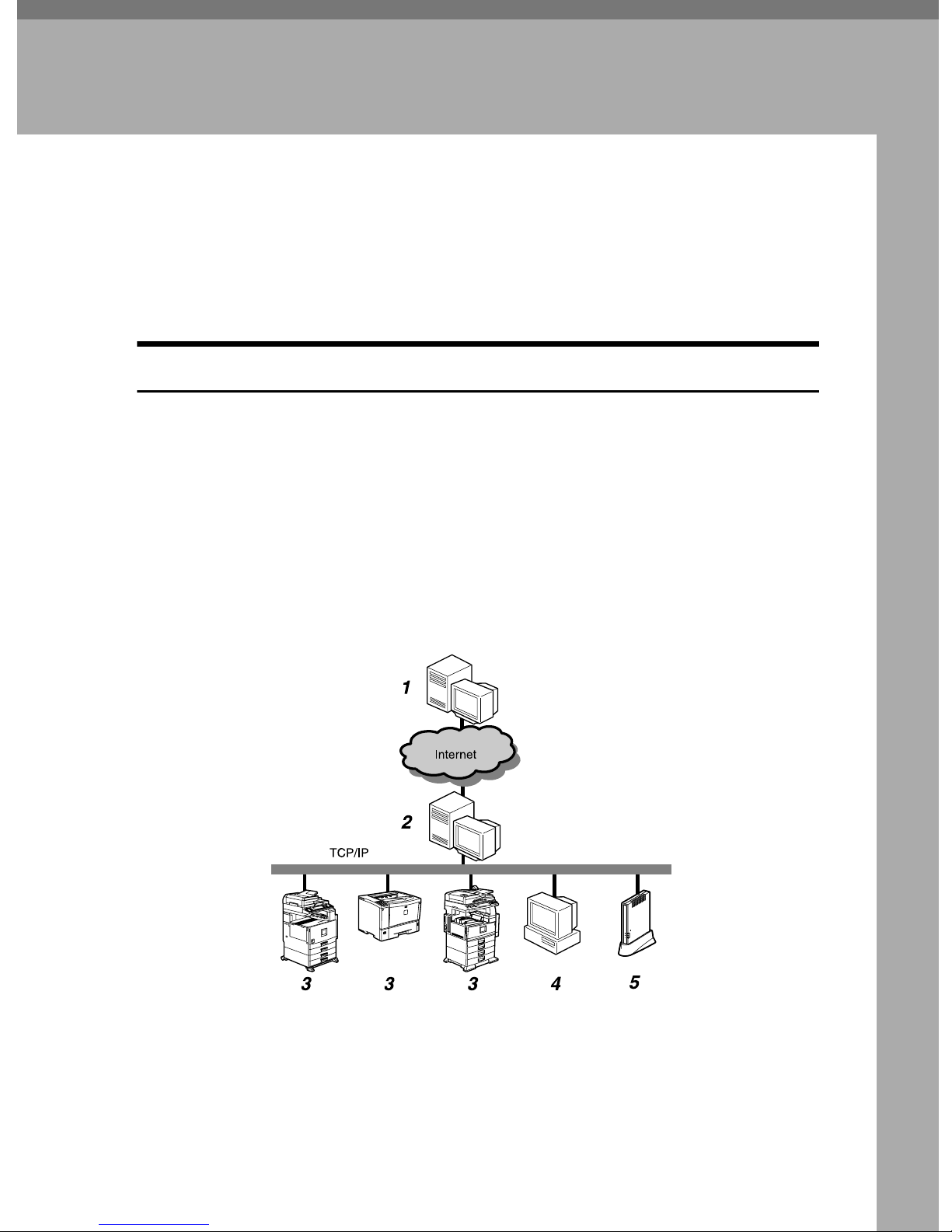
E-mail (SMTP) Method
In this method, collected information is sent to the Communication Server automatically by E-mail. To use this method, an environment which enables to send
E-mail with the SMTP protocol is required.
With “E-mail (SMTP)” method, the equipment will search the image I/O devices on the network. This is called “Auto Discovery. ” The searched information
will be sent to the Communication Server. You are able to receive our advice according to the sent information. For example, for a better image I/O device layout.
E-mail is encrypted by S/MIME for secure communication.
1. Communication Server
Information sent from the equipment by
E-mail will be aggregated to this server.
2. SMTP Server
SMTP Server responds by E-mail. You
are able to use the system if your environment is able to use E-mail with the SMTP
Protocol. This server can be the server of
your ISP, and does not have to be the
server on your local network.
AAA319S
1

1
About the Remote Communication Gate
3.
Image I/O Devices on the Network
This equipment can collect information
from digital MFPs and printers by Auto
Discovery. The Auto Discovery enables
you to control information of as many as
500 devices. The equipment may not be
able to collect information from some devices.
4. Computer for Setting
The equipment is set by RC Gate Monitor.
For example, Auto Discovery settings.
5.
This Equipment (Remote Commu-
nication Gate Type BN1)
This Equipment manages and sends various information from other devices to
the Communication Server.
Internet encryption communication (HTTPS) Method
In this method, the equipment communicates with the Communication Server
by HTTPS. This method allows the equipment to communicate with the Communication Server by HTTPS using mutual authentication. Communication is
secured with this protocol. The Communication Server works as the HTTPS
server, and the equipment works as the HTTPS client, to exchange information.
In addition to the periodical detection (Auto Discovery function) of the image
I/O devices on the network, the Internet encryption communication (HTTPS)
enables you to receive remote control services and to collect more detailed information from the Communication Server, taking advantage of its interactive
communications.
Your system will be “Always connected” method or “Dial-up” method according to your connection to the internet.
2
Outline of the System
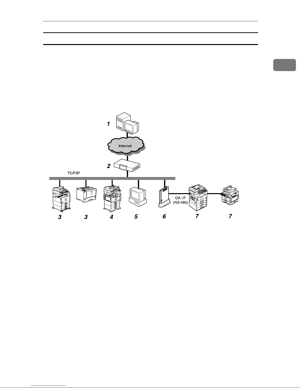
Always Connected Method
If your network is connected to the internet, the equipment will communicate
with the Communication Server using that environment. Here, we call it the “Always connected” method.
When you use the “Always connected” method, the following two items must
be cleared: 1. Your environment is arranged to be able to access websites outside
of your network; and 2. When using proxy certification, the account and password for the equipment is available.
1
1. Communication Server
Information sent for various services will
be aggregated to this server.
2. Proxy Server and/or Firewalls
You are able to use your proxy server and
firewalls. When using proxy, Basic and
Digest authentication are supported and
automatically decided.
3. Registered Image I/O Devices on
the Network
This equipment can manage digital MFPs
and printers by communicating with the
Communication Server. The equipment
can manage a maximum of 100 devices,
including “7. Image I/O Devices Registered without the Network.” The “Auto
Discovery” function works with these
devices as well. Ask your service representative for the compliant devices, as the
equipment cannot manage some devices.
AAA317S
4. Non Registered Image I/O Devic-
es on the Network
This equipment can collect information
from non-registered digital MFPs and
printers and send it to the Communication Server by using the “Auto Discovery”
function. The equipment cannot collect information from some devices. The Auto
Discovery enables you to control information of as many as 500 devices.
5. Computer for Administration
This computer administers the equipment by use of the RC Gate Monitor.
6.
This Equipment (Remote Commu-
nication Gate Type BN1)
Intermediates managed image I/O devices and the Communication Server.
Sends various information from other devices to the Communication Server, and
receives software to update the devices.
3

1
About the Remote Communication Gate
7. Image I/O Devices Registered
without the Network
Regarding the digital MFPs and copy
machines unconnected to the Network,
you can control them by directly connecting to this equipment using the RS-485
modular cable (black). The image I/O devices on the Network can also be controlled by the modular cable connection
for more detailed services. (For the devices unconnected to the Network, however, you cannot use the Auto Discovery).
A total of 5 devices can be connected to
the Network. There are some devices,
however, that cannot be connected with
the modular cable. Please contact your
maintenance service representative and
ask about the compliant devices. The actual connection operation is to be conducted by your service representative.
4
Outline of the System
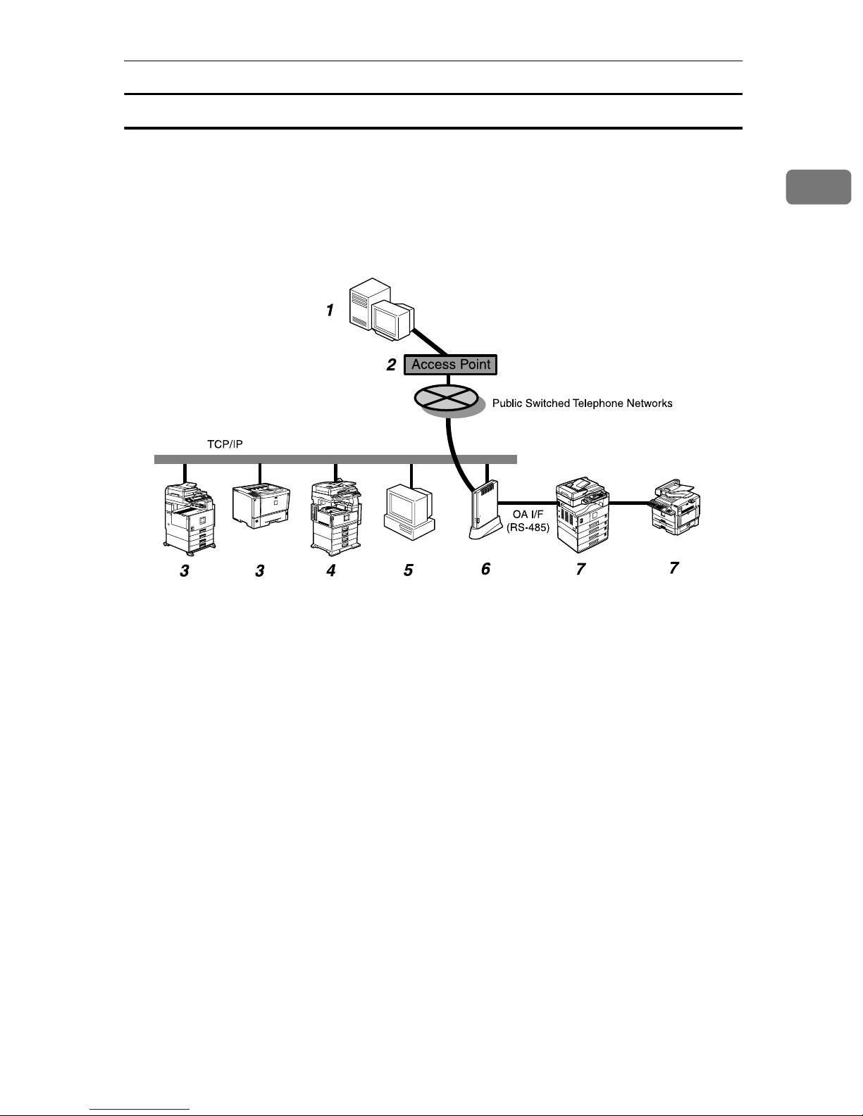
Dial-up Method
If your network environment is not suitable for the “Always connected” method
(For example, you cannot connect to a website on the internet), connect the
equipment to the Communication Server with the modem installed in Type
BM1. This is called the “Dial-up” method. For this method, you can use the facsimile line or telephone line exclusively prepared for this equipment.
1
1. Communication Server
Information sent for various services will
be aggregated to this server.
2. Access Point
You can make a setting by selecting a
country name from among [Access point]
list in [RC Gate Registration Wizard].
3. Registered Image I/O Devices on
the Network
This equipment can manage digital MFPs
and printers by communicating with the
Communication Server. The equipment
can manage a maximum of 100 devices,
including “7. Image I/O Devices Registered without the Network.” The “Auto
Discovery” function works with these
devices as well. Ask your service representative for compliant devices, as the
equipment cannot manage some devices.
AAA318S
4. Non Registered Image I/O Devic-
es on the Network
This equipment can collect information
from non-registered digital MFPs and
printers and send it to the Communication Server by using the “Auto Discovery” function. The equipment cannot
collect information from some devices.
The Auto Discovery enables you to control information of as many as 500 devices.
5. Computer for Administration
This computer administers the equipment by use of the RC Gate Monitor.
6.
This equipment (Remote Commu-
nication Gate Type BM1)
Various information concerning the image I/O devices managed by this equipment are sent to the Communication
Server. It communicates with the Communication Server via the modem installed in this equipment.
5

1
About the Remote Communication Gate
7. Image I/O Devices Registered
without the Network
Regarding the digital MFPs and copy
machines unconnected to the Network,
you can control them by directly connecting to this equipment using the RS-485
modular cable (black). The image I/O devices on the Network can also be controlled by the modular cable connection
for more detailed services. (For the devices unconnected to the Network, however, you cannot use the Auto Discovery).
A total of 5 devices can be connected to
the Network. There are some devices,
however, that cannot be connected with
the modular cable. Please contact your
maintenance service representative and
ask about the compliant devices. The actual connection operation is to be conducted by your service representative.
6
Guide to the Equipment
Guide to the Equipment
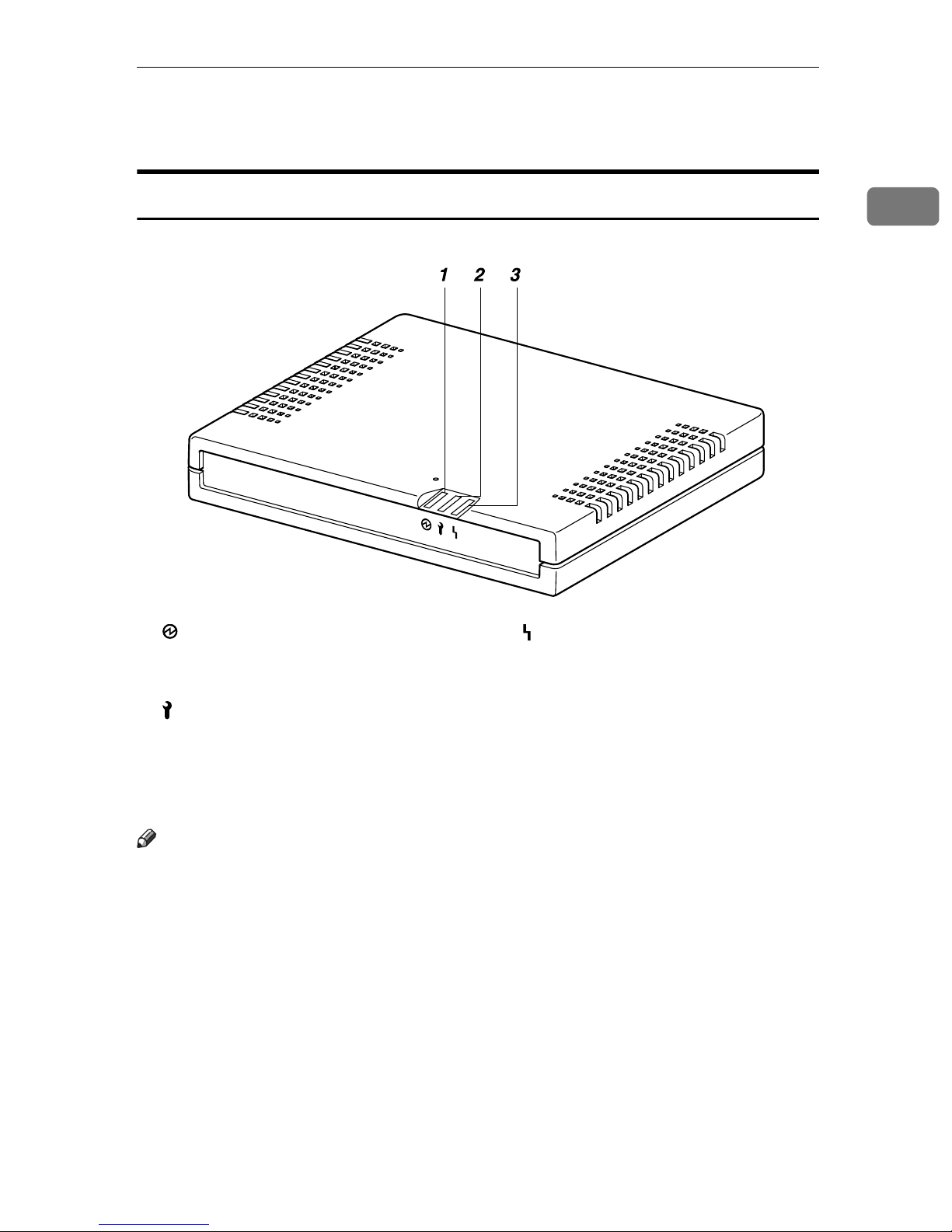
Top/Front
1. Power
Lights green while the equipment is operating.
2. Call Maintenance
OFF when correctly started. Lights red
when an error occurs. In this case, contact
your service representative.
1
AAA302S
3. Communication Error
OFF when correctly communicating with
the Communication Server. Lights orange when access to the Communication
Server fails. Check the LAN cable is correctly connected. Connect the power cable if it not connected. Contact your
service representative if the problem persists.
Note
❒ When re-booted and started, the LED blinks for a while.
❒ If the equipment stops functioning due to error, the red and orange LEDS
flash rapidly and alternately. Call your service representative if this happens.
7
1
About the Remote Communication Gate
Back
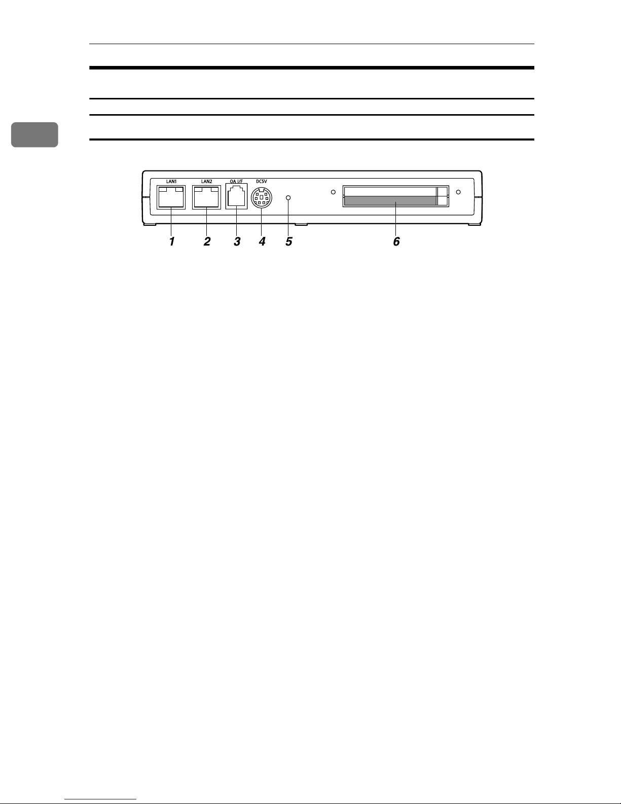
Remote Communication Gate Type BN1
AAA401S
1. LAN1 Port
The network (Ethernet) interface port for
maintenance. The IP address of the port
is set at 192.168.10.1 as the factory default, but you can change the address to
192.168.1.1 or 192.168.250.1. This is used
by the service engineer for the maintenance of this equipment, and also used
for the first LAN2 port IP address setting
by the administrator.
2. LAN2 Port
The network interface port to connect
this equipment to the network. The default IP address is 192.168.0.2, but it can
be changed.
3. OA I/F
This is an RS-485 interface port to be connected to the image I/O devices to collect
information without connection setting
via Network. The modular cable (black)
is used for the connection. Contact your
service representative for the connection
service. The actual connection operation
is to be conducted by your service representative.
4. Power Socket
Connect to the power cable.
5. Screw Hole
A hole for a screw to set the bracket.
6. A port for Wireless LAN Card
(Option)
An optional LAN Card interface for the
network connection of this equipment.
8
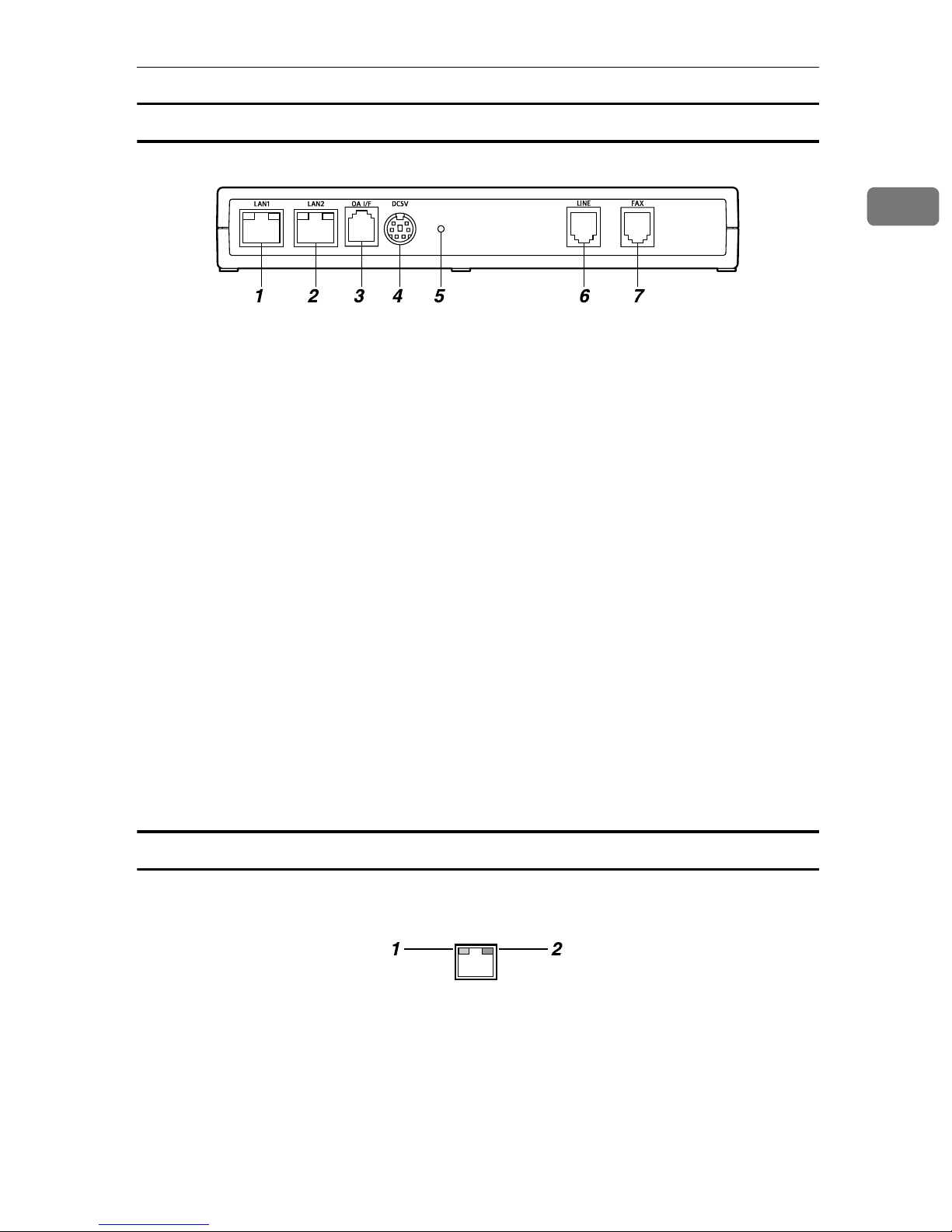
Remote Communication Gate Type BM1
Guide to the Equipment
1
AAA015S
1. LAN1 Port
The network (Ethernet) interface port for
maintenance. The IP address of the port
is set at 192.168.10.1 as the factory default, but you can change the address to
192.168.1.1 or 192.168.250.1. This is used
by the service engineer for the maintenance of this equipment, and also used
for the first LAN2 port IP address setting
by the administrator.
2. LAN2 Port
The network interface port to connect
this equipment to the network. The default IP address is 192.168.0.2, but it can
be changed.
3. OA I/F
This is an RS-485 interface port to be connected to the image I/O devices to collect
information without connection setting
via Network. The modular cable (black)
is used for the connection. Contact your
service representative for the connection
service. The actual connection operation
is to be conducted by your service representative.
4. Power Socket
Connect to the power cable.
5. Screw Hole
A hole for a screw to set the bracket.
6. LINE
Interface port to connect the telephone
line.
7. FAX
Interface port to connect the FAX line
when using the same line with your FAX.
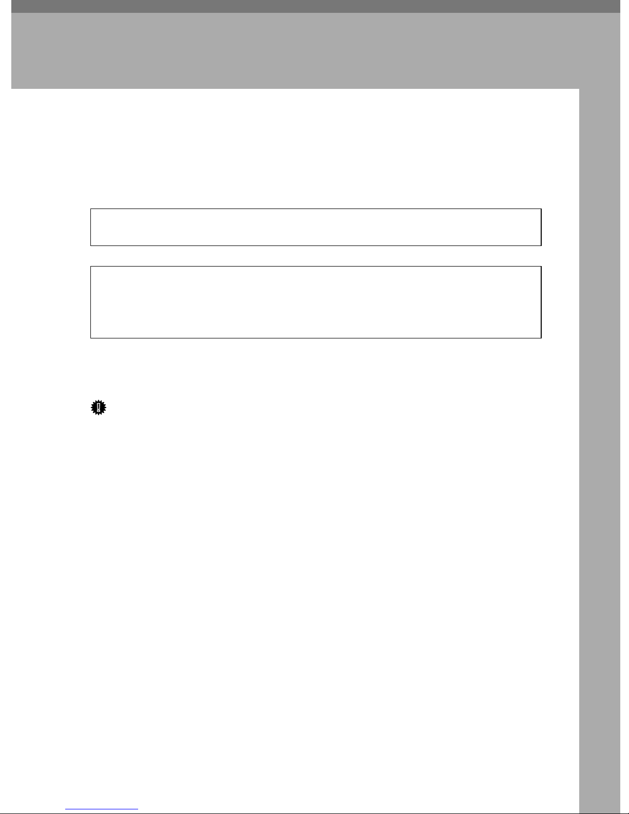
LAN Port Indicator
You can check the connection condition of the LAN1 port and the LAN2 port.
1. Orange
This color lights on when connected to
the 100 Mbps network. Lights off when
connected to the 10Mbps network or is
not connected to the network.
AAA017S
2. Green
This color lights on while transmitting
data.
9

1
About the Remote Communication Gate
10
2. Setup and Connection
R
R
This chapter will describe how to setup and connect the equipment to the network.
Checking the Setup Environment
WARNING:
• Confirm that the wall outlet is near the equipment and easily accessible so as to be unplugged quickly in an emergency.
CAUTION:
• Keep the equipment away from humidity and dust. Otherwise a fire or an
electric shock might occur.
• Do not place the equipment on an unstable or tilted surface. If it topples
over, an injury might occur.
Place the equipment on a level and vibration free surface.
Place the equipment on a location that guarantees a space of 0.4inch (1cm) or
more from the front/back/left/right sides of the equipment.
Important
❒ Do not locate the equipment where it is exposed to:
• direct sunlight
• air conditioner, heater, or humidifier emission
• electronic/magnetic interference from radios, televisions, or other electrical equipment
• Areas excessively cold, hot, or humid
• extreme heat, cold, or humidity
❒ Locate this equipment in a secure environment such as an enclosed office.
❒ This equipment supports manufacturer original I/O devices only.
❒ Connect this equipment and the image I/O devices to a responsibly adminis-
trated network that is protected by a firewall or a similar Internet security/virus protection facility.
❒ Choose reliable persons as the administrator and registrant. The administra-
tor is responsible for management and operation of the equipment; the registrant is responsible for registering the equipment on the Communication
Server. Both must read the "Operating Instructions" and "Setup Guide" carefully.
11
2
Setup and Connection
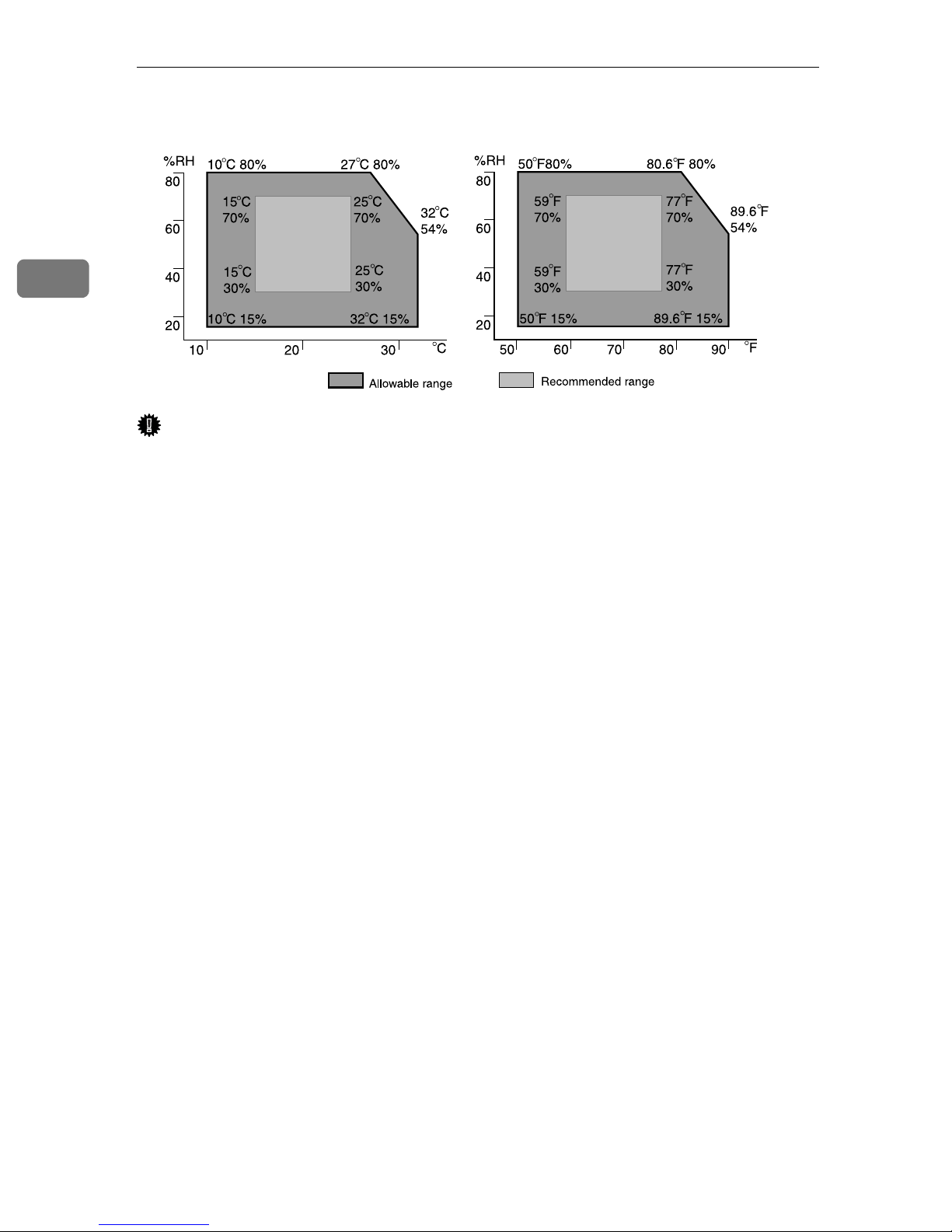
Place the equipment in the recommended temperature and humidity shown below:
AAA323S
Important
❒ When the equipment is moved from a cold to a warm location, or vice versa,
internal dew condensation can occur. In this case, allow the equipment to acclimate to the new environment for at least one hour.
❒ Keep the equipment's power on during normal operation.
12
Connecting the Power Cable
R
Connecting the Power Cable
This procedure shows you how to connect the power cable to the equipment.
WARNING:
• The supplied power cord is for use with this equipment only. Do not
use with other appliances. Doing so may result in fire, electric shock,
or injury.
• Use the AC adapter supplied with the equipment. Otherwise, a fire, an
electric shock, a equipment failure might occur.
• Connect the equipment only to the power source described on this
manual. Connect the power cord directly into a wall outlet and do not
use an extension cord.
• Do not damage, break or make any modifications to the power cord.
Do not place heavy objects on it. Do not pull it hard nor bend it more
than necessary. These actions could cause an electric shock or fire.
2
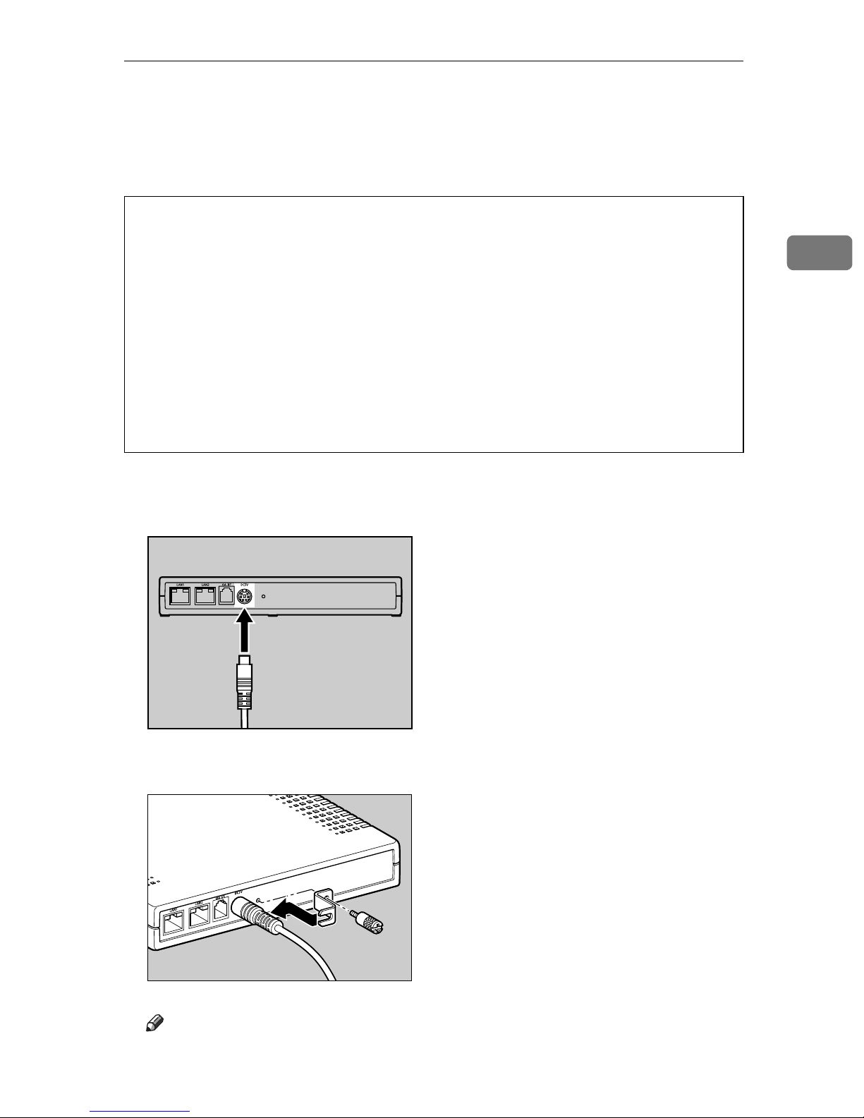
A Connect the AC adapter to the power cable.
B Connect the AC adapter securely to the power socket of the equipment.
AAA001S
C Secure the Power Cable with the Bracket and fix it with the screw.
Note
❒ Use a coin when you fix the screw.
AAA002S
13
2
R
R
R
Setup and Connection
D Plug the power cable into the wall outlet.
Note
❒ The LED blinks when the equipment is warming up or in maintenance
mode, and the orange and green LEDs are lit.
❒ For details about the shutdown procedure, see p.98 “Shut Down RC Gate”.
WARNING:
• Do not plug in or out with wet hands.
CAUTION:
• When you disconnect the power plug from the wall outlet, always pull the
plug (not the cable).
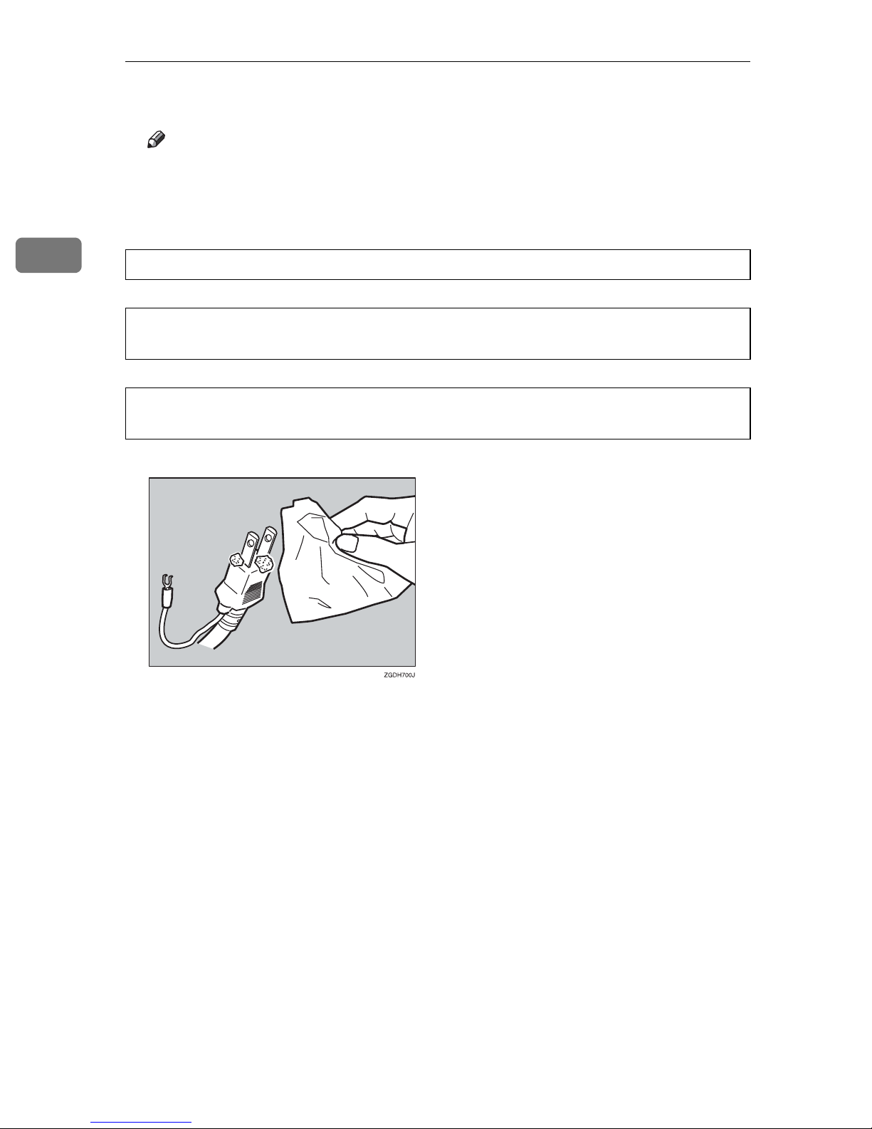
CAUTION:
• Clean the plug end of the power cable at least once a year so as to avoid a
possible fire.
14
 Loading...