

Ricoh re10 Service Manual

RICOH NC305
EDITOR

20 December 1991 SPECIFICATIONS
1. SPECIFICATIONS
Maximum Original Size: A3/LDG
Error Tolerance: +2.5 mm
Functions: Delete Area Mode
Save Area Mode
Black in Area Mode
Color in Area Mode
Highlight Color Mode
Size Magnification Mode
Dimensions:
(W x D x H)
Weight: Approximately 2.6 kg (5.8 lb)
Power Source: 5 V 0.25 A (from copier)
528 mm x 468 mm x 54 mm
(20.8" x 18.5" x 2.2")
(including stylus and cable)
1

ELECTRICAL COMPONENT LAYOUT 20 December 1991
2. ELECTRICAL COMPONENT LAYOUT
2
1
3
1. Main PCB
2. Stylus
3. Positioning Sheet
2

20 December 1991 ELECTRICAL COMPONENT DESCRIPTIONS
3. ELECTRICAL COMPONENT DESCRIPTIONS
PCBS
Main Controls the Editor and drives the posit ion ing sheet
Others
Positing Detects the stylus position
Stylus Initializes detection of the position
3
BASIC OPERATION 20 December 1991
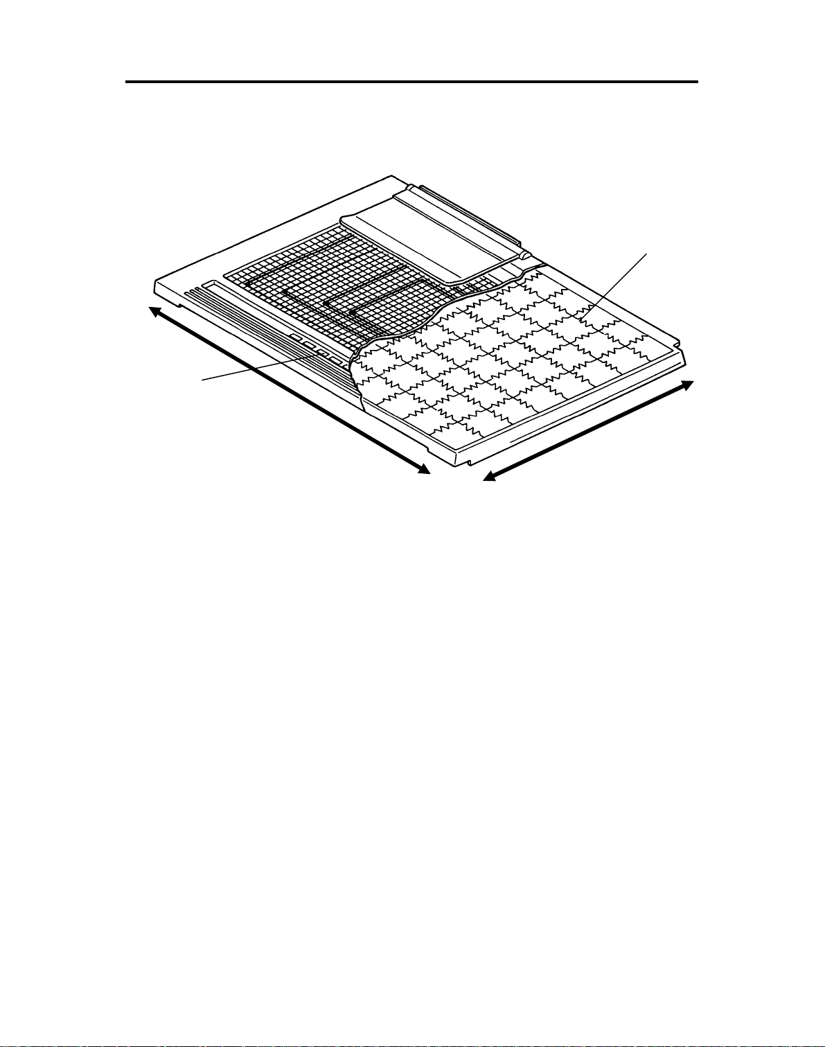
4. BASIC OPERATION
[A]
[B]
Y
X
There are resistors [A] (carbon sheets) in th e positioning sheet aligned in the
X and Y directions. When part of the posit ion ing sheet is pressed with the
stylus pen, voltage corresponding to the combination of the resistors is
detected.
The detected data is transmitte d to the copie r as the coord inate position. This
detection method also ap plie s t o th e mod e sele ction pads [B].
4
 Loading...