

Page 1

RC-210 SERVICE MANUAL
(Machine Code: G549)
Page 2

TABLE OF CONTENTS
1. OVERALL MACHINE INFORMATION........................................ 1-1
1.1 BASIC SPECIFICATIONS..........................................................................1-1
1.2 OTHER SPECIFICATIONS........................................................................1-2
1.3 PAPER SIZE..............................................................................................1-2
2. DETAILED DESCRIPTIONS....................................................... 2-1
2.1 FUNCTIONAL OVERVIEW ........................................................................2-1
2.1.1 SYSTEM LAYOUT ............................................................................2-1
2.1.2 CONTROLLER BOARD LAYOUT.....................................................2-1
2.1.3 DEVICE FUNCTIONS.......................................................................2-2
2.2 PRINT DATA PROCESSING.....................................................................2-3
2.2.1 IMAGE DATA PROCESSING FLOW................................................2-3
2.2.2 UCR (IPD-C)......................................................................................2-4
2.2.3 PURE BLACK FUNCTION (R-PS2) ..................................................2-4
2.2.4 R-PS2 COLOR MANAGEMENT SYSTEM........................................2-4
3. INSTALLATION PROCEDURE................................................... 3-1
3.1 MINIMUM SPACE REQUIREMENTS ........................................................3-1
3.2 CONTROLLER INSTALATION...................................................................3-2
3.2.1 ACCESSORY CHECK ......................................................................3-2
3.2.2 INSTALLATION PROCEDURE.........................................................3-3
1.1.3 INITIAL SETTING..............................................................................3-4
4. SERVICE TABLES...................................................................... 4-1
4.1 SERVICE PROGRAM (SP) MODES..........................................................4-1
4.1.1 HOW TO ENTER SP MODE.............................................................4-1
4.1.2 SP MODE FUNCTIONS....................................................................4-1
4.1.3 SP MODE TABLE..............................................................................4-3
1.2 POWER-UP SELD-DAIGNOSTICS............................................................4-6
1.3 DETAILED SELF-DIAGNOSTICS..............................................................4-7
5. REPLACEMENT AND ADJUSTMENT ....................................... 5-1
5.1 GAMMA CORRECTION.............................................................................5-1
5.2 SOFTWARE UPGRADE PROCEDURE.....................................................5-1
6. TROUBLESHOOTING................................................................ 6-1
6.1 ERROR MESSAGE....................................................................................6-1
6.1.1 OVERVIEW.......................................................................................6-1
6.1.2 DETAILED MESSAGES....................................................................6-2
7. NETWORK INTERFACE BOARD (C4000 FERRET).................. 7-1
7.1 OVERVIEW................................................................................................7-1
7.1.1 SPECIFICATIONS.............................................................................7-1
7.1.2 BLOCK DIAGRAM.............................................................................7-1
i
Page 3

7.2 COMPONENT LAYOUT.............................................................................7-2
7.2.1 NETWORK INTERFACE BOARD DIAGRAM ...................................7-2
7.2.2 DEVICES...........................................................................................7-2
7.3 BASIC OPERATIONS ................................................................................7-3
7.3.1 OVERVIEW.......................................................................................7-3
7.3.2 SWITCH FUNCTION.........................................................................7-4
ii
Page 4
14 September 2000 BASIC SPECIFICATIONS
1. OVERALL MACHINE INFORMATION
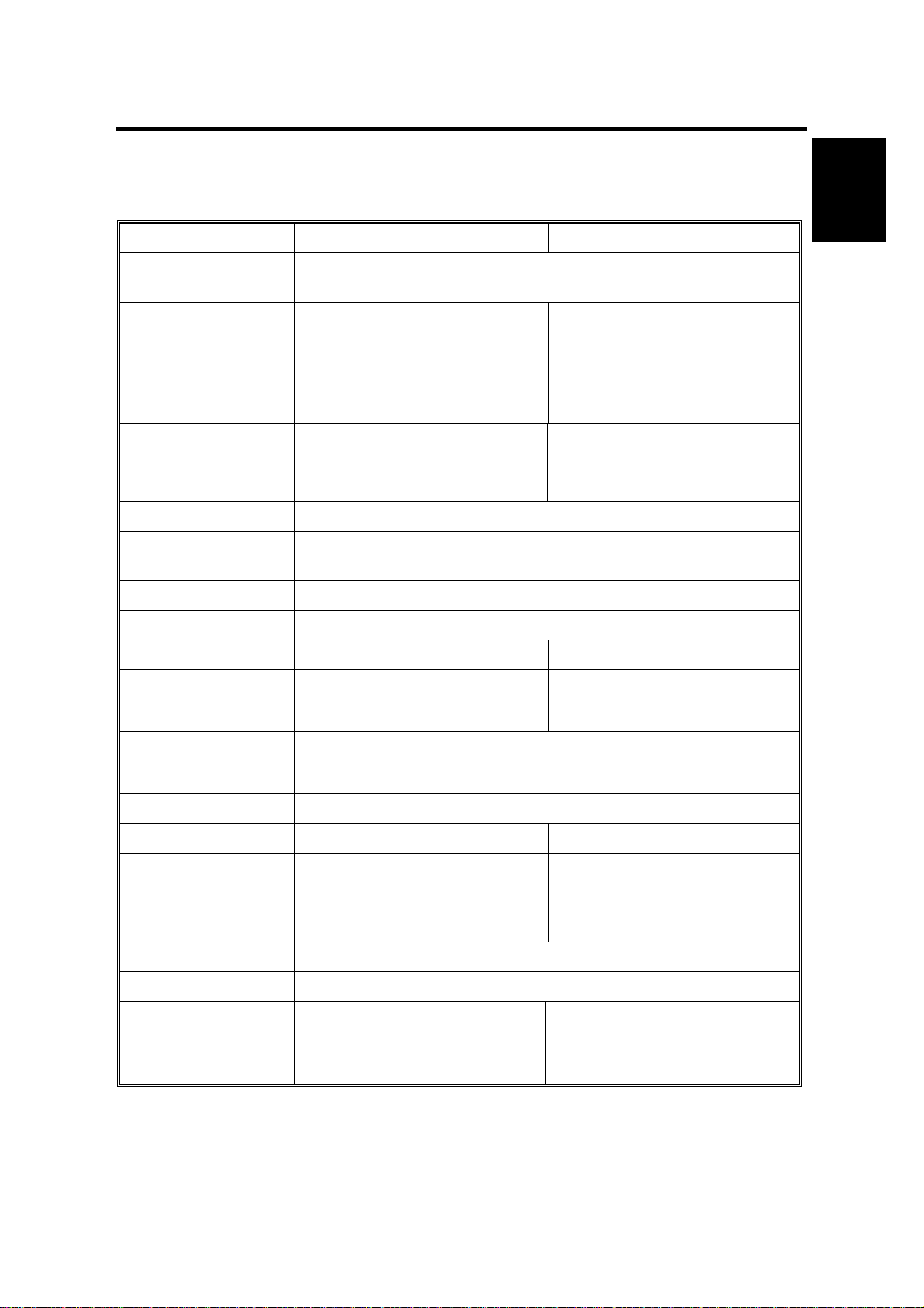
1.1 BASIC SPECIFICATIONS
RC-200 RC-210
Page Description
Language:
Printer Driver:
Resolution: 600 x 600 dpi 600 x 600 dpi
Color Mode: Color (2C or less/3C or more), B&W
Gradation Mode: 2/4/16 gradation levels (1/2/4 bits/pixel) Default setting: 4
Toner Saving: On/Off (printer driver setting) Default Setting : Disabled
Color Correction: On/Off (printer driver setting) Default setting: Enabled
IPDL-C (Intelligent Page Description Language for Color) RPS2
(RICOH-SCRIPT2)
• IPDL-C: Windows 95/98/NT
4.0
• RPS2: Windows 95/98//NT
4.0, Macintosh (PPD for
LaserWriter 8)
gradation levels
• IPDL-C: Windows
95/98/2000 NT 4.0
• RPS2: Windows
95/98/2000/NT 4.0,
Macintosh (PPD for
LaserWriter 8)
Enhanced 4800 x 600 dpi with
smoothing
Overall
Information
Paper Size: See next page
Print Speed:
Interface:
Fonts: Ricoh-Script 2: 39 Roman fonts
CPU: R4310 176MHz R5261 200MHz
RAM: 96MB (Standard and
ROM: 2MB Flash ROM
Scanner Function: Not supported
Option: None
• Color: 4 ppm (A4 sideways)
• B&W: 14 ppm (A258 model)
18 ppm (A259/A260 models)
• Parallel port (IEEE1284B: Compatible / Nibble / ECP
supported)
• 100 BASE-TX, 10 BASE-T
maximum)
• Color: 6 ppm (A4 sideways)
• B&W: 25 ppm (B018 model)
31 ppm (B017 model)
64MB (Standard)
- with optional memory 128MB (additional 64MB)
192MB (additional 128MB)
• Controller Interface Type H
• Memory Unit Type B (64 MB)
• Memory Unit Type B (128
MB)
1-1
Page 5

OTHER SPECIFICATIONS 14 September 2000
1.2 OTHER SPECIFICATIONS
RC-200 RC-210
LAN Interface: 100 BASE-TX, 10 BASE-T
Frame Type: Ethernet II, IEEE802.2, IEEE802.3, SNAP
Network Protocol: TCP/IP, IPX/SPX, NetBEUI, AppleTalk (with RPS2)
SNAP: MIB-II, Printer MIB, Host Resource MIB, Ricoh Private MIB
1.3 PAPER SIZE
The same as the base model (RC-200).
1-2
Page 6
14 September 2000 FUNCTIONAL OVERVIEW
2. DETAILED DESCRIPTIONS
2.1 FUNCTIONAL OVERVIEW
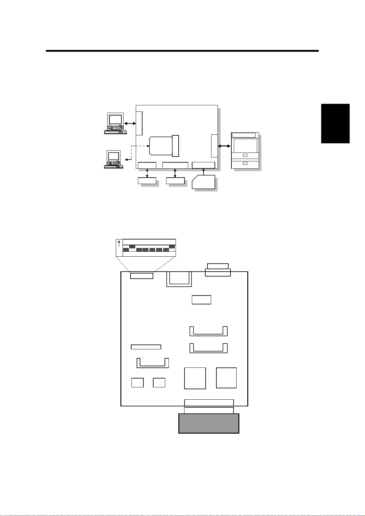
2.1.1 SYSTEM LAYOUT
Controller
Bord
CN4
Option I/F
CN1 & 2
DIMM SLOT (x2)
DIMM
CN3
IC CARD I/F
IC Card
Control Panel
Engine
ENGINE I/F
G549D501.WMF
Host
Host
CN7
IEEE1284 I/F
Network
Board
(Standard)
CN5 CN6
ROM SLOT
RPS
Detailed
Descriptions
2.1.2 CONTROLLER BOARD LAYOUT
DIP Switch
1234
O
N
DIP SW (SW1)
OPTION BUS I/F (CN 4)
ROM SLOT (CN5)
FONT
ROM
5678
IC CARD I/F (CN 6)
FLASH
ROM
O
FF
NVROM
DIMM SLOT (CN2)
DIMM SLOT (CN1)
ASIC
EAGLE2
ENGINE I/F (CN3)
CENTRO I/F (CN 7)
CPU
RM5261
2-1
Copier Engine
G549D502.WMF
Page 7
FUNCTIONAL OVERVIEW 14 September 2000
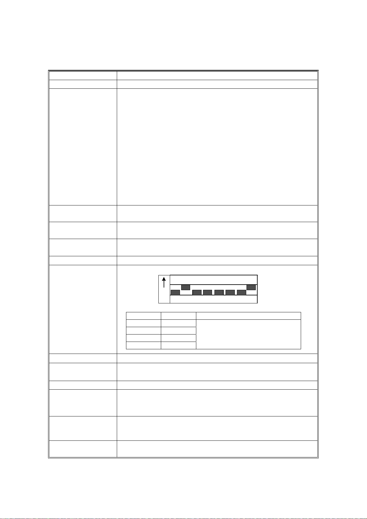
2.1.3 DEVICE FUNCTIONS
Device Function
CPU VR5261- 200 ( 200MHz)
ASIC EAGLE 2 This ASIC controls the following:
• Memory mapping
• Rest
• DRAM
• Data received from the parallel
• Timer
• Parallel interface
• I/O Port
• Image data compression & decompression
• Engine interface serial communications control
• Interrupt
• Data through function
• Toner saving control
FLASH ROM Stores program (2MB) The flash ROM is programmable via an
IC card.
NVRAM Stores the initial settings and printer parameters.
(8KB EEPROM)
FONT ROM Stores internal printer fonts (Japanese fonts not used).
(One 64-Mbit mask ROMs)
DRAM
DIP SW
64MB DIMM standard memory. (96MB total)
DIP Switch
1234
O
N
G549D512.WMF
SW No. Setting Content
1OFF
2ON
3 - 7 OFF
8ON
Do not touch these switches in the
field.
5678
O
FF
ENGINE I/F (CN 3 )
PARALLEL I/F
(CN7)
• Embedded CIVIC interface
• Provides an interface that connects to a local host
(IEEE1284 compliant).
OPTION I/F (CN4) Network interface
ROM SLOT (CN5)
• A 72-pin slot for accommodating the Ricoh-Script 2
emulation module.
• The emulation module is programmable by flash ROM.
DIMM SLOT (CN1 &2)Slots for accommodating the memory. Standard size is 64MB.
The memory size can be increased to 128MB or 192MB
maximum (with additional 64MB or 128MB memory).
IC CARD SLOT
(CN8)
Accommodates an IC card to upgrade firmware.
2-2
Page 8
14 September 2000 PRINT DATA PROCESSING
2.2 PRINT DATA PROCESSING
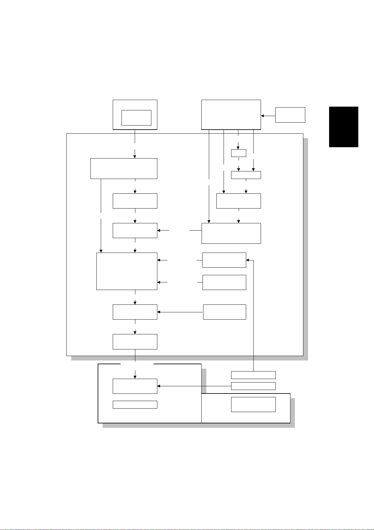
2.2.1 IMAGE DATA PROCESSING FLOW
IPDL-C Driver
CMS
RGB
UCR
R=G=B : Replace with K
(Black Text/Graphic)
RGB 8bit
CMYK Conversion
UCR
K
CMYK 8bit
Maximum Toner
Amount Control
CMYK 8bit
Gamma
Correction
CMYK
8bit
Correction
Correction
R-PS2 Driver
RGB 8bit
CMYK 8bit
CMYK Conversion
Pure Black
K=100% : C=M=Y=0
(Text/Graphic)
Calibration
Manual Gamma
Correction
RGB 8bit
CIE
Lab
UCR
RGB 8bit
Color
CMS
Detailed
Descriptions
Lab
CRD
RGB 8bit
CMYK 8bit
Dithering
CMYK 1/2/4bit
8bit Expansion
CMYK 8bit
Copier Gamma
Correction
LD Control Board
Copier Engine
1/2/4bit
Text/Photo Dither
Controller
Color Calibration
ACC
Scanner IPU
Board
Scanner
G549D506.WMF
2-3
Page 9
PRINT DATA PROCESSING 14 September 2000
2.2.2 UCR (IPD-C)
If the R/G/B data is equal (R=G=B), 100% UCR is applied only in the Black
Text/Graphic mode. Even if gray color is processed with RGB data, gray color will
be duplicated only with black toner if the RGB data is completely equal. This
function gives faster productivity. (This function was adopted on the base model,
RC-200.)
2.2.3 PURE BLACK FUNCTION (R-PS2)
For this new function, if the K value is 100% as a result of UCR (CMYK conversion)
in Text/Graphic mode, all CMY values becomes zero. This avoids colored text.
2.2.4 R-PS2 COLOR MANAGEMENT SYSTEM
Depending on the color setting (Off / Vivid / Supper Vivid / Fine / Super Fine),
image processing of color management differs as shown in diagram on the
previous page. (This CMS is the same as the base mode, RC-200.)
Data Sent From
Driver
CMYK data - CMYK data passes through the CRD.
RGB
Lab -
Driver Color
Setting
Off RGB data passes through the CRD.
Vivid,
Supper Vivid
Fine,
Supper Fine
Image Processing In Controller
• RGB data is converted to CMYK with
almost 100% UCR.
The difference between Vivid and Supper
•
Vivid is the amount of CMY added to K to
give depth to images.
• RGB data is converted to Lab data; t hen,
the Lab color space is converted to a
targeted color space by using an em bedded
CRD or CRD downloaded from an
application.
• The difference between Fine an d Supper
fine is the target color space.
• Lab data is converted to the targeted color
space by using embedded C RD or CRD
downloaded from applicatio n.
2-4
Page 10
14 September 2000 MINIMUM SPACE REQUIREMENTS
3. INSTALLATION PROCEDURE
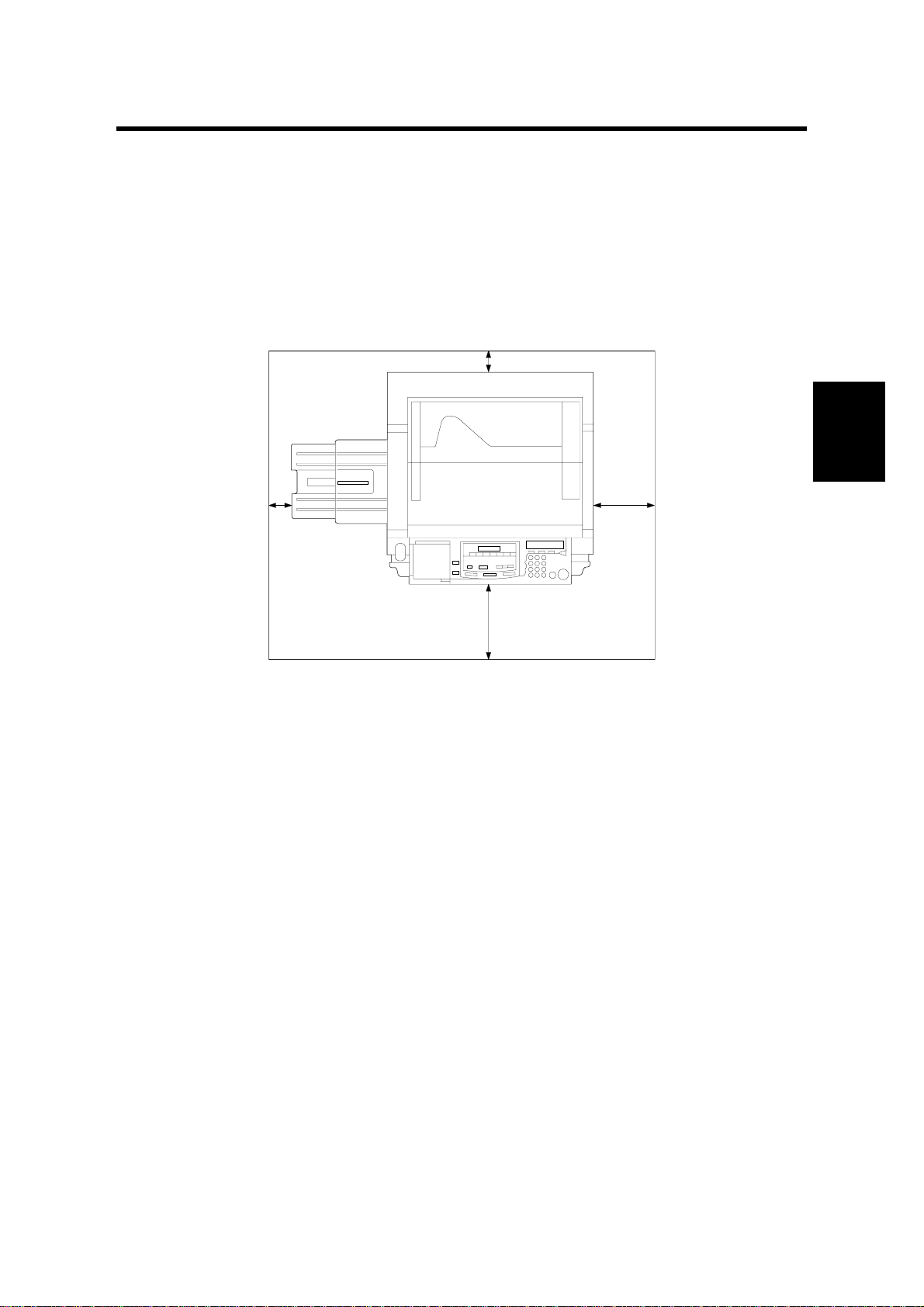
3.1 MINIMUM SPACE REQUIREMENTS
Provide clearance for the copier, as shown below. If one or more options (such as
the ADF or sorter stapler) are added to the copier, this clearance should be
provided around the entire system. Please refer to the copier service manual for
more details concerning space requirements for this copier.
Installation
G549I123.WMF
NOTE: A space of at least 10 cm (3.9") at the rear of the machine is important for
machine ventilation.
3-1
Page 11

CONTROLLER INSTALATION 14 September 2000
3.2 CONTROLLER INSTALATION
3.2.1 ACCESSORY CHECK
Check the quantity and condition of the accessories in the box with the following
list:
Description Quantity
1. Controller.................................................................................... 1
2. LCD Panel.................................................................................. 1
3. CD ROM..................................................................................... 1
4. Operating Instructions (G549-17)
English ....................................................................................... 1
5. Operating Instructions (G549-27)
English, German, French, Italian, Dutch..................................... 1
6. Installation Procedure (G549-17 only)........................................ 1
7. Screw M3x6................................................................................2
8. Screw M4x8................................................................................4
3-2
Page 12

14 September 2000 CONTROLLER INSTALATION
3.2.2 INSTALLATION PROCEDURE
NOTE: To install this option, the I/F kit (B381) is required.
The maximum output voltage from the controller is DC 5V.
[B]
Installation
[A]
G549I107.WMF
G549I106.WMF
[C]
G549I201.WMF
!
CAUTION
Unplug the copier power cord before starting the following procedure.
1. Remove the I/F cover [A] (4 screws).
2. Cut off and remove the cap [B].
3. Slide the controller unit [C] into the I/F unit and secure the controller (6 screws).
4. Reinstall the I/F cover.
3-3
Page 13

CONTROLLER INSTALATION 14 September 2000
[E]
[A]
[B]
[D]
[C]
G549I101.WMF
5. Remove the LCD cover [A].
6. Pull the LCD harness [B] out (1 clamp [C]).
7. Connect the connector [D] to the LCD panel and install the panel [E] in the
operation panel.
3.2.3 INITIAL SETTING
1. After the controller installation is completed, check if the printer function works
properly by printing out the configuration page.
2. Perform ACC for printer mode on the copier.
3. Perform Color Calibration on the controller.
NOTE: When performing Color Calibration for the controller, first execute ACC for
printer mode on the copier.
3-4
Page 14

14 September 2000 SERVICE PROGRAM (SP) MODES
4. SERVICE TABLES
4.1 SERVICE PROGRAM (SP) MODES
4.1.1 HOW TO ENTER SP MODE
Error Data In
IPDL-C
Ready
On Line
2
1
4
G528D504.WMF
EnterEscapeReset
MenuMedia
35
First press the Reset, On Line, (the screen will display "Offline"), and then press
the Enter key as shown.
When accessing SP mode, the SP mode menu is added to the “Job Timeout”,
“Maintenance” and “Media” menu. To exit the controller from SP mode, follow the
procedure for entering SP mode or turn the main switch off and on. (This returns
the controller to normal mode.)
NOTE: When accessing SP mode, “SP” is dis played on the screen. Do not forget
to exit SP mode after servicing, because users may change the settings or
clear all the settings by accident.
Tables
Service
4.1.2 SP MODE FUNCTIONS
Job Timeout Menu
The following menu is added to the Maintenance section.
Menu Function
3. MinLineWidth
[Minimum Line
Width]
Prints lines with the dot (1 to 4 dots) selected.
When a thin line is not clearly visible on output, this mode can
change the thickness of the line.
NOTE:
• If the application does not support line command, this mode
does not function.
• If this mode is activated, this affects all kinds of line data and
causes a side effect. Therefore, normally this mode should be
off.
4-1
Page 15

SERVICE PROGRAM (SP) MODES 14 September 2000
Maintenance Menu
The following menu is added to the Maintenance section. The part highlighted in
gray is newly added for RC-210.
Menu Function
S1. ColorChart
[Color Chart]
S2. ClearAllMem.
[Clear All Memory]
Prints the color test chart stored in the controller. The dither
mode can be selected by pressing the Media key. These color
test charts are used for checking the image quality.
Dither Modes: 1, 2 and 4 bit Photo and Text.
• The color test chart can be printed on any supported paper
size.
• The pattern layout (size) differs depending on the selected
paper size.
Resets all parameters stored in the NVRAM and network board
to their default values.
The Menu Rest in the User menu only resets all the settings and
data for the User menu.
NOTE:
When clearing the memory, if you do not want to clear the
network settings, execute the Clear All Memory after removing
the network board.
S3. Gamma.Calib.
[Gamma Calibration]
S4. Toner Level Independently adjusts the ID level for CMYK.
S5. Printer ID The printer ID is required to download fonts for RPS2 onto the
S6. Toner Limiter Sets the maximum toner amount for image development.
Adjusts the gamma for highlight, middle, shadow, and ID max of
CMYK independently.
NOTE:
When an image quality problem concerning the color balance or
gradation occurs, check or perform maintenance on the copier
first. Then, adjust the printer gamma when users require fine-
tuning.
HDD. However, this controller does not have an HDD. Therefore,
the printer ID is not used.
Media Menu
The following menu was added to the Media section.
Menu Function
3. Summary Displays the firmware version and memory size on the screen.
4-2
Page 16

14 September 2000 SERVICE PROGRAM (SP) MODES
4.1.3 SP MODE TABLE
When accessing SP mode, the SP mode menus are added to the User menus. The
menus consist of some steps depending on the menu. The following table shows
the steps to access a menu and the selectable mode or data.
NOTE: 1) The bolded value or mode is the default setting.
2) Refer to the Operating Instructions for the detailed function of each User
menu.
3) The bolded and Italic menus in step 2 are only accessible in SP mode.
4) The menus highlighted in gray are new or the menu specifications were
changed from the base model (RC-200).
1. Menu Key
1st step 2nd step 3rd step
IPDL-C
RPS2
System
System
1. Job Timeout
2. I/O Timeout 000 (Off) to 999 seconds
3. MinLineWidth 1 to 4 Dots
4. Toner Usage
1. Color Level 1 / 2 / 4 bit
2. Color Mode
3. Color Set
4. Color Profile
5. Smoothing
6. Toner Saving
7. Dithering
8. Paper Type
9. Auto Tray SW
A. Auto Duplex
B. Duplex Bind
C. Collate / Stack
D. Face UP / Down
E. Job Timeout
F. I/O Timeout 000 (Off) to 999 seconds
G. Feed Timeout 000 (Off) to 999 seconds
H. Printer Error
I Ktalk Mode Not effective
J. Parallel IF1
1. Paper Tray
2. I/O Buffer
3. Transfer
4. PDL Sensing
5. Image Memory
6. Parallel
7. Bi-direction
8. OHP Slip
000 (Off) to 999 seconds
300Sec
Off / On
Color or B&W
Off / Vivid / Super Vivid / Fine / Super Fine
Photograph / Presentation / Solid Color
Off / Auto
Off / On
Auto / Photographic / Text
Plain Paper / OHP / Thick Paper
On / Off
Off / On
Short edge / Long edge
Off / Sort / Stack
Face Down / Face Up
000 (Off) to 999 seconds
300Sec
60Sec
Off / On
System Default / ACK inside / ACK Outside
Tray 1 / Tray 2 / Tray 3 / Tray 4 / Bypass
16KB / 32KB / 64KB / 128KB / 256KB / 512KB
Hi-speed / Normal
Auto / Manual
Off / On
ACK Inside / ACK Outside / STB Down
Original Mode / Standard
On / Off
Tables
Service
4-3
Page 17

SERVICE PROGRAM (SP) MODES 14 September 2000
1st step 2nd step 3rd step
System
System
Maintenance
Print List
9. Printer Lang.
[ Printer Language ]
10. Language
32. IP Address
33. Subnet Mask
34. Gateway Add
[Gateway Address]
35. Access CTL
[Access Control]
36. Access Mask
37. Net Boot
[Network Boot]
38. Frame NW
[Frame Type NW]
39. Active PTL
1. Color Calib.
[Color Calibration]
2. Menu Reset “Press # key”
3. Menu Protect Off / On (See NOTE.)
4. Log Protect Off / On (See NOTE.)
5. Log Clear “Press # key”
6. Ethernet Auto / 10Mbps / 100Mbps (See NOTE.)
S1. ColorChart
[Color Chart]
S2. ClearAllMem.
[Clear All Memory]
S3. Gamma.Calib.
[Gamma Calibration]
S4. Toner Level
S5. Printer ID
S6. Toner Limiter
1. Config. Page “Press # key”
2. Job Log “Press # key”
3. Statistics “Press # key”
IPDL-CSelect PDL
Option#1 RPS2
IPDL-C / RPS
English / French / German / Italian / Dutch /
/ Japanese
011.022.033.044
000.000.000.000
000.000.000.000
000.000.000.000
000.000.000.000
ARP+PING / ARP&RARP / ARP&BOOTP /
ARP&RARP&BOOTP / None / RARP+TF TP /
BOOTP / RARP&BOOTP / DHCP
Auto Select / Ethernet 802.3 / Ethernet 802.2 /
Ethernet 2 / Ethernet SNAP
All Active / None / TCP/IP Only / NetWare Only /
TCP&NetWare / EtherTalk Only / TCP&EtherTalk /
NetW&EtherTalk TCP&NW&EtherTK / NetBEUI Only
/ TCP&NetBEUI / NetW&NetBeui / TCP&NW&NB /
ETalk&NetBeui / TCP&ETK&NB / NW&ETK&NB
See the following table for details.
“Press # key”
“Press # key”
See the following table for details.
Cyan / Magenta / Yellow / Black
Not used
See the following table for details.
Spanish
NOTE: The menus, Menu Protect, Log Protect, and Ethernet are not displayed by
pressing the [Menu] key. To access these menus, press the [Enter],
[Escape], and [Menu] keys in sequence when the printer is on-line.
This procedure was added for system/network administrators in order to
avoid changing the settings by accident.
4-4
Page 18

14 September 2000 SERVICE PROGRAM (SP) MODES
2. Media key
1st step 2nd step
1. Paper Tray
2. By-pass
Size
3. Summary
Tray1 / Tray2 / Tray3 / Tray4 / Byps
A3 (L) / B4(L) / A4(S) / A4(L) / B5 (S) / B5 (L) / A5(S) / A5 (L) / B6 (L) / A6(L) /
11x17(L) / 8.5x14(L) / 8.5x13(L) / 11x8.5(S) / 8.5x11 (L) / 8.5x5.5(S) /
5.5x8.5(L) / 8x13(L) / 8.25x13 (L)
RC-210 / RWC / RPS / EtherNET / Total Memory
3. Gamma Calibration & Toner Limiter & Toner Level
2nd step 3rd step 4th step 5th step 6th step
See
NOTE.
0 to 30
(15)
S3.
Gamma
Calib.
S4.
Toner
Level
NOTE.
S5.
Toner
Limiter
1. 2 bit
2. 4 bit
3. 1 bit
Cyan
Magenta
Yellow
Black
Text
Photo
1. Test Pattern
2. Correction
3. Restore “Press # key”
- <-----+-----> +
Data: 100 to 400 (%)
(260)
Data: 100 to 400 (%)
(260)
“Press # key”.
1 to 32
• Photo / K, C, M, Y / H, M, S,
IDmax
• Letter / K, C, M, Y / H, M, S,
IDmax
Tables
Service
NOTE: For dither processing, 8-bit CMYK data is compressed to 1, 2, or 4 bits.
The controller expands the data into 8 bits again for data processing of the
engine. Changing the toner level setting in SP mode increases or
decreases the data level in the 8-bit expansion process. This SP mode can
adjust the ID level for output.
4. Color Calibration
2nd step 3rd step 4th step 5th step 6th step
1. Color
Calib.
1. 2bit
2. 4 bit
3. 1 bit
1. Test Pattern “Press # key”
“Complete”2. Calibrate “Set Pattern on Glass, Press #”
“Error Press #
to Retry”
3. Restore “Press # key”
4-5
Page 19

POWER-UP SELD-DAIGNOSTICS 14 September 2000
4.2 POWER-UP SELD-DAIGNOSTICS
Code ROM sum check
Check RAM memory size
Read/Write test
Check RAM sum check
Frequency check
Test of timer functions
Operation test
Font ROM sum check
DIMM sum check
Clock generator check
Turn on power
Test Code ROM
Test Standard RAM
Test Standard RAM
Test RAM
Test CPU
Test Timer
Test FPU
Test Font ROM
Test DIMM
Test Clock Generator
Fatal Error Detected
Fatal Error Detected
Fatal Error Detected
Fatal Error Detected
Fatal Error Detected
Fatal Error Detected
Fatal Error Detected
Fatal Error Detected
Fatal Error Detected
Display Error on LCD
Non-fatal Error
Detected
Non-fatal Error
Detected
Start System
Non-fatal Error
NO
Stand-by Condition
Store Error Information
YES
Print List of Settings
(Black/White)
G549D711.WMF
4-6
Page 20

14 September 2000 DETAILED SELF-DIAGNOSTICS
4.3 DETAILED SELF-DIAGNOSTICS
Code ROM sum check
Check RAM memory size
Read/Write test
Check RAM sum check
Frequency check
Test of timer functions
Read/Write test
Operation test
Loop back test
Read/Write test
Turn on power
Test Code ROM
Test Standard RAM
Test Standard RAM
Test RAM
Test CPU
Test Timer
Test Optional RAM
Test FPU
Test Parallel Interface
Test NVRAM
Fatal Error Detected
Fatal Error Detected
Fatal Error Detected
Fatal Error Detected
Fatal Error Detected
Fatal Error Detected
Fatal Error Detected
Fatal Error Detected
Fatal Error Detected
Fatal Error Detected
Fatal Error Detected
Tables
Service
Operation test
DIMM sum check
Clock generator check
Test Font ROM
Test DIMM
Test Clock Generator
Start System
Non-fatal Error
NO
Print List of Settings
(Color)
Stand-by Condition
Fatal Error Detected
Display Error on LCD
Non-fatal Error
Detected
Non-fatal Error
Detected
Store Error Information
YES
Print List of Settings
(Black/White)
G549D712.WMF
4-7
Page 21

14 September 2000 GAMMA CORRECTION
5. REPLACEMENT AND ADJUSTMENT
5.1 GAMMA CORRECTION
Same as the base model (RC-200).
5.2 SOFTWARE UPGRADE PROCEDURE
The controller, Ricoh-Script 2, and network interface boards have a flash ROM for
storing control software. This allows version upgrades using an IC card.
The engine firmware cannot be upgraded in this way. See the engine service
manual for details on how to change this board.
NOTE: Before starting an upgrade procedure, make sure that the software in the
IC card is newer than the software in the controller, Ricoh-Script 2, or
network interface board.
To check, do one of the following:
• Print out a configuration page (user mode).
• Enter controller SP mode and execute “3. Summary” with the [Media]
key. The software version is shown on the operation panel LCD.
Follow the procedure shown below to upgrade the software:
1. Turn off the machine, and then unplug all cables from parallel interface boards
and network interface board, if connected.
2. Remove the handle of the controller (2 screws).
3. Install the IC card in the card slot.
4. Turn on the machine. The machine automatically copies the software from the
IC card to the appropriate IC (controller, Ricoh-Script 2, or network interface
board).
CAUTION: Do NOT turn off the machine while the software is being updated.
Otherwise, the controller, NIB, or Ricoh-Script 2 module may be
damaged.
Adjustment
Replacement
5-1
Page 22

SOFTWARE UPGRADE PROCEDURE 14 September 2000
For the controller or Ricoh-Script 2:
The LCD display on the operation panel changes as shown below as the
rewrite procedure proceeds. (‘MELT’ is displayed during the software upgrade
for Ricoh-Script 2 since it involves a decompression process.)
(MELT ->) ERASE -> WRITE -> VERIFY -> OK!!OK!!
The appearance of the message “OK!!OK!!” indicates that the controller has
received the data from the IC card. However, note that it takes about 30
seconds to rewrite the data in the controller or Ricoh-Script 2 after this message
is displayed.
The message NG!!NG!!” is displayed if an error occurs during the rewrite
process. If this condition occurs, reinstall the IC card and turn the power off and
on again.
For the network interface board:
The appearance of the message “DOWNLOAD OK.” indicates that the
controller has received the data from the IC card. However, note that it takes
about 30 seconds to rewrite the data in the network interface board after this
message is displayed.
DOWNLOAD -> ############ -> DOWNLOAD OK.
The message “DOWNLOAD NG.” is displayed if an error occurs during the
rewrite process. If this condition occurs, reinstall the IC card and turn the power
off and on again.
1. When the rewrite ends, turn off the main switch, and remove the IC card.
2. Reinstall the handle of the controller.
3. Turn the power on again and print the configuration page.
4. Check the new software version and make sure that it matches the version on
the IC card.
5-2
Page 23

14 September 2000 ERROR MESSAGE
6. TROUBLESHOOTING
6.1 ERROR MESSAGE
6.1.1 OVERVIEW
The following types of status and error messages are shown in the table below.
Each message type displays a different priority on the panel screen. When the
controller detects different types of status or errors at the same time, it displays the
message that has the higher priority. Th en the Error indicator will light as shown in
the table.
Type of message Description
Internal Error Controller is out of control. Light
Self-diagnostics
Error
Controller System
Error
SC Code (Copier) Copier cannot be used due to an SC
Warning Error
(Copier)
System Status Displays the status message while
Caution Status
(Copier)
Controller Data
Read Error
Emulation Status Displays the controller status, i.e.
Controller detects error during selfdiagnostics.
Controller cannot work due to a
malfunction.
code.
Copier cannot be used due to status
error. Controller stops ripping and
cancel it depending on the time-out
setting.
the copier is warming up.
Copier can be still used Light
Controller detects that received data
is wrong.
“Initializing”, “Waiting”, “Printing” so
on.
Error
Indicator
Light
Light
Light
Light
Not light
Not light
Not light
Priority
HIGH
LOW
Trouble-
shooting
6-1
Page 24

ERROR MESSAGE 14 September 2000
6.1.2 DETAILED MESSAGES
1. Status Messages
Type Message Descripti on Location / Action
The copier is under the
warm-up or process
control self-check.
diagnostic mode.
Controller is offline status.
The controller cannot
accept or print data.
printing job.
processed.
the next data to print.
System is rebooted or
print job is now being
canceled.
by-pass table.
Toner i ndicated (xxx) is
almost empty (toner near
end condition)
The staples are almost
empty.
There is no paper
indicated (YYY) in the
paper tray.
Toner i ndicated (xxx) is
empty (toner end
condition).
Paper is left in the duplex
tray.
Paper is left in the sorter
bins.
The duplex tray is not
installed correctly.
Paper jam occurs in the
copier.
• Wait until the copier is in
the ready condition.
• Wait until the controller is in
the ready condition.
• Press the Online key to
switch the status.
• Initialization of RPS-2 mode
• The printer is in ready
condition to print.
• Wait for a while. This
message appears only in
the RPS-2 mode.
• Wait for a while.
• Wait for a while.
• Wait for a while.
• Load the indicated paper in
the by-pass table.
• Replenish indicated toner.
• xxx is a color of toner or
CMYK combination.
• Replenish the staples.
• Load the indicated paper in
the paper tray.
• Replenish the indicated
toner.
• Remove paper from the
duplex unit.
• Remove paper from the
sorter bins.
• Reinstall the duplex unit
properly.
• Remove the jammed paper
according to the display on
the copier.
System
Status
Emulation
Status
Caution
Status
Warning
Status
Warming Up
Please Wait The controller under selfOffline
Initializing RPS-2 is initializing.
Ready T he controller is ready for
Printing Doing print job.
Processing Print data is being
Waiting Controller is waiting for
Resetting
Load Paper There is no paper in the
Low on: xxx
Add Staples
Load
YYY
Add Toner
xxx
Remove
Paper From
Duplex Tray
Remove
Paper From
Sorter
Reset Duplex
Tray Correctly
Clear
Misfeed(s)
Trouble-
shooting
6-2
Page 25

14 September 2000 ERROR MESSAGE
Type Message Descripti on Location / Action
Close Door(s)
Doors or covers are open.
• Close doors or covers.
/ Cover(s)
Warning
Status
Power Off /
On
No: XXX
Add Fuser Oil The oil tank is empty.
Waste Toner
Internal error occurs.
The used toner tank is full.
• Turn the main switch off
and on. Fix the problem if it
still occurs.
• Fix the problem.
is Full
Call Service
SC:99
SC code detected on the
copier.
Code number is fixed to
“99” when the copier
detects SC condition.
6-3
Trouble-
shooting
Page 26

ERROR MESSAGE 14 September 2000
2. Controller Error (System or Data Rea d Error)
Error codes highlighted in gray are newly added.
Type Error Code Description Location / Action
System
Error
Data
Read
Error
A3: Error
A6: Error
AB: Error
B0: Error
B1: Error
B3: Error
B4: Error
B5: Error
B7: Error
B9: Error
85: Error
86: Error
91: Error
94: Error
Too much data for
the I/O buffer to
handle
Not enough memory
to print one or more
pages in the job
The controller is
unable to process the
data of job sent
Optional memory
error
Error in the standard
parallel interface
Wrong printer setting
Error in the IC card
slot
Error in RPS2
module
Error in the network
interface board
Error in clock
generator
Error in standard
memory
Wrong p rinter driver
selected / Wrong
interface cable used
Error in the standard
memory
Error in the standard
memory
• Check if the interface cable is
inserted into the controller and your
computer securely.
• Check if the interface cable is
damaged.
• Increase the size of I/O buffer.
• Change the Color Level using the
printer driver to set the image
resolution to [Fast], or change the
Color Level to [1 bit]. Turn on “Image
Memory” using the printer’s “System
Menu”.
• Reduce the amount of data being
sent to the controller.
•
Reinstall/replace optional memory.
• Check the interface cable is inserted
properly or damaged.
• Check controller.
• Reset the controller using “Menu
Reset”
• Check the IC card or controller.
• Reinsert or replace the RPS2
module.
• Reinsert or replace the network
interface board.
•
Check or replace the controller
board.
• Check or replace the controller
board.
• Check if the correct printer drive is
used.
• Check the setting on the driver.
• Check or replace the controller
board.
• Check the total memory size setting
on the driver.
Trouble-
shooting
6-4
Page 27

14 September 2000 ERROR MESSAGE
3. Self-diagnostics error
When a contro ller self-diagnostic error o ccurs, the error code is displayed on the
first line of the screen panel
The second line contains an 8-digit code that gives details of the error for
designers to debug.
• For a memory error, the second line of the panel screen indicates the address in
which the error occurred.
• For errors other than memory errors, the second line always reads “FFFFFFFF”.
Error codes highlighted in gray are newly added.
Error
Code
00XX Exception processing error
01XX Flash ROM sum check error
0201 Standard memory read/write error
0301/
0401
06XX CPU exception self-diagnostics error
0D0X ASIC timer error
0FXX ASIC engine interface error
110X ASIC Centronics interface error
1401 NVRAM error
160X Font ROM error
1B0X Optional Interface Error
200X C l o ck Gen erator Error
250X DIMM (emulation module) error
400X FPU error
Optional memory read/write error
Non-fatal error (printed as B0 in the error log.)
Non-fatal error (printed as B1 in the error log.)
Non-fatal error (printed as B5 in the error log):
2501 & 2507
Description Location
• Controller Board
•
Controller Board
• Controller Board
Controller Board
•
• Controller Board
• Controller Board
•
Controller Board
• Controller Board
• Controller Board
• Controller Board
• Controller Board
•
Controller Board
• RPS2 module (DIMM)
(See NOTE.)
• Controller Board
• Controller Board
Trouble-
shooting
NOTE: If the DIMM is not properly set in the slot or is defective and if the controller
detects it, the controller boots up in IPDL-C mode. In this case, the
controller seems to be OK, however, print-jobs fail if customers use RPS2
for printing. It is necessary to check whether the DIMM is properly installed
in the slot or defective.
6-5
Page 28

ERROR MESSAGE 14 September 2000
4. INTERNAL ERRORS
When an inte rnal error occurs, the message “Power Off / On” is displayed on the
first line of the p anel screen. The internal error code, “No. XXYY-ZZZZZZZZ) is
displayed on the second line of the panel screen. (“XX” denotes a classification
code, “YY” denotes a process number, and “ZZZZZZZZ” denotes the program
address where the error occurred.)
The classification code portions “XX” and their description are as shown below.
“YY” and “ZZZZZZZZ” portions are for designer use only (for debugging).
Code
(Part of “XX”)
00 Error in the TLB user area.
01 CPU TLB update exception
02 CPU mismatch exception (load or fetch)
03 CPU mismatch exception (store)
04 CPU address error exception (load or fetch)
05 CPU address error exception (store)
06 CPU bus error exception (load or fetch)
07 CPU bus error exception (store)
08 CPU system call exception
09 CPU break point exception
10 CPU reserved instruction exception
11 CPU coprocessor disabled exception
12 CPU operation overflow exception
13 CPU trap exception
14 Coherency (instruction) error
15 CPU floating-point operation exception
16 CPU time r int e rrupt
17 ROCKY level 4 interrupt (ART or Tim)
18 ROCKY level 3 inter rupt (C)
19 ROCKY level 2 inter rupt (XINT1 or XINT0)
20 ROCKY level 1 inter rupt (CBE, DBE, Dtc0, EAGLE, EAGLEErr)
21 ROCKY level 0 inter r u pt (Debug)
22 Software interrupt
23 Software interrupt
24 Other CPU exceptions
25 Memory allocation error
26 Overflow error
27 Frame allocation error
28 Card eject error
29 Printer engine error
30 Option board error
31 Session-to-network interface board communication error
Description
Trouble-
shooting
6-6
Page 29

14 September 2000 OVERVIEW
7. NETWORK INTERFACE BOARD (C4000 FERRET)
7.1 OVERVIEW
7.1.1 SPECIFICATIONS
Configuration: Embedded
LAN Interface: 100BASE-TX/10BASE-T
Frame Type: Ethernet II, IEEE802.3, IEEE802.2, SNAP
Protocol: TCP/IP, AppleTalk, NetWare, NetBEUI
SNAP: MIB-II, Printer MIB, Host Resource MIB, Ricoh Private MIB
7.1.2 BLOCK DIAGRAM
Controller
Board
Option Bus I/F
Network
Environment
CPU
ASIC
Ethernet
Controller
Filter Module
LAN I/F
Flash ROM
1MB
SDRAM
8MB (64Mb)
EEPROM
1Kb
Option
7-1
G549O501.WMF
Page 30

COMPONENT LAYOUT 14 September 2000
7.2 COMPONENT LAYOUT
7.2.1 NETWORK INTERFACE BOARD DIAGRAM
Flash
ROM
MB87L1231
7.2.2 DEVICES
ASIC
SDRAM
CPU
HD6417612
Ethernet
Controller
AM79C973
RJ-45
LED4(G)
LED3(G)
EEPROM
LED1(Y)
SW2
G549O500.WMF
Device Description
CPU HD6417612RF
ASIC MB87L1231
Flash ROM MBM29LV800BA-70PFTN (8 Mbit)
SDRAM 64Mbit: 100MHz
EEPROM M93C46-WMN6 (1kbit)
Ethernet Controller AM79C973KC/W
7-2
Trouble-
shooting
Page 31

14 September 2000 BASIC OPERATIONS
7.3 BASIC OPERATIONS
7.3.1 OVERVIEW
This network board can manage both 100BASE-TX and 10BASE-T. It has a
maximum data transfer speed of 100Mbps.
The auto-negotiation function automatically switches the communication speed.
The controller board supplies the power source (+5V) and provides the reset
signal. The controller board communicates with the network interface board
through the option I/F connector.
The function of LED and SW is as follows;
Functions
LED1
LED2 Not used
LED3
LED4
SW1
Displays the operating status.
ON: Ready, OFF: Busy
Displays the LAN Type.
ON: 100 BASE-TX, OFF: 10 BASE-T
Displays the link status.
ON: Link safe, OFF: Link failure or Link disable
Resets the NVRAM on the network interface board.
NOTE:This board has the hardware to execute a “Summary Printout”.
However, it does not function on this printer due to the controller
specifications.
7-3
Option
Page 32

BASIC OPERATIONS 14 September 2000
7.3.2 SWITCH FUNCTION
SW1 resets the NVRAM on the network interface board.
NOTE: This board has the hardware to execute a "Summary Printout". However, it
does not function on this printer due to controller specifications.
NVRAM Reset Procedure
This procedure resets all the network settings to the defaults.
• IP address, Subnet Mask, Default Gateway Address, Access Control Mask,
Network Boot, Frame Type (NetWare), Active Protocol, and so on
1. Turn on the main switch while pressing SW1. Keep pressing SW1 for 15
seconds.
2. Release SW1 for 3 seconds, press it again for 3 seconds, and then release it.
NOTE: There is a margin of less than 1 second for error. Use a watch to
measure the time periods as accurately as possible.
3. Turn the main switch off/on to complete the NVRAM reset procedure.
4. Print out the configuration page, and then check the settings. If the procedure
failed, the previous settings remain. Repeat the above procedure until the old
settings have been cleared.
Trouble-
shooting
7-4
 Loading...