How it Works
Log In / Sign Up
Buy Points
How it Works
FAQ
Contact Us
Questions and Suggestions
Users
RICOH
Loading...
R
R2061
R2062
R2221L
R2221T
R2223L
R2223T
R3
8
R30
7
R3111 Series
R3111x
R3111x Series
2
R3111xxx1A-C
R3112x
R3114x
R3116x
R3117xxx1
R3117xxx2
R3117xxx3
R3117xxx4
R3118x
R3119N
2
R3132x
2
R3133D
R3133x
R3134x
R3150N
R3200x
2
R4
7
R40
6
R5
6
R50
10
R5101G001A
R5101G002A
R5101G003A
R5101G004A
R5101G005A
R5102V001A
R5104V
R5105N
2
R5106N
R5107G
R5108G
R5109G
R5220x
R5312L001A
R5322N
2
R5323x
2
R5325K
R5325x
R5326K
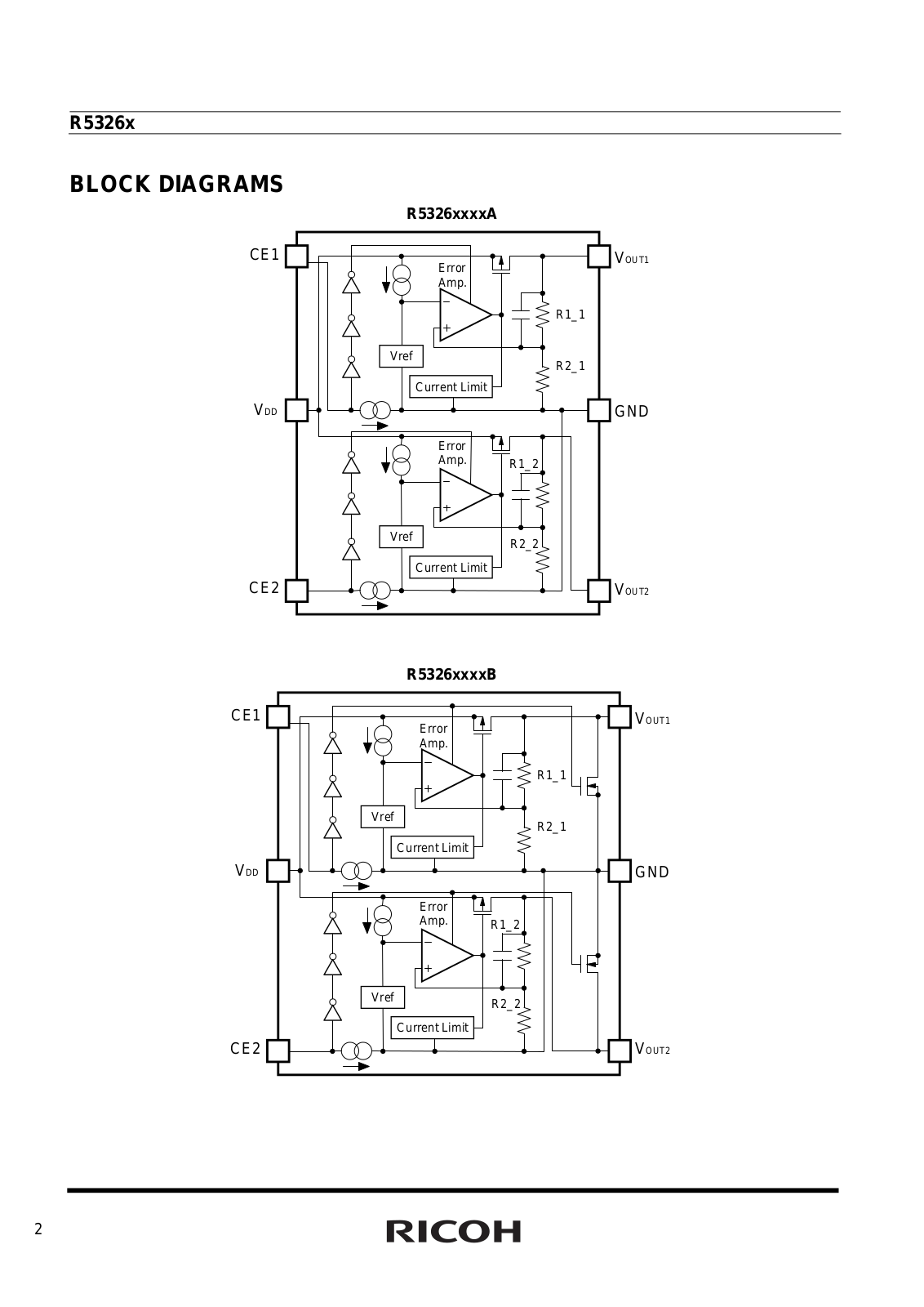
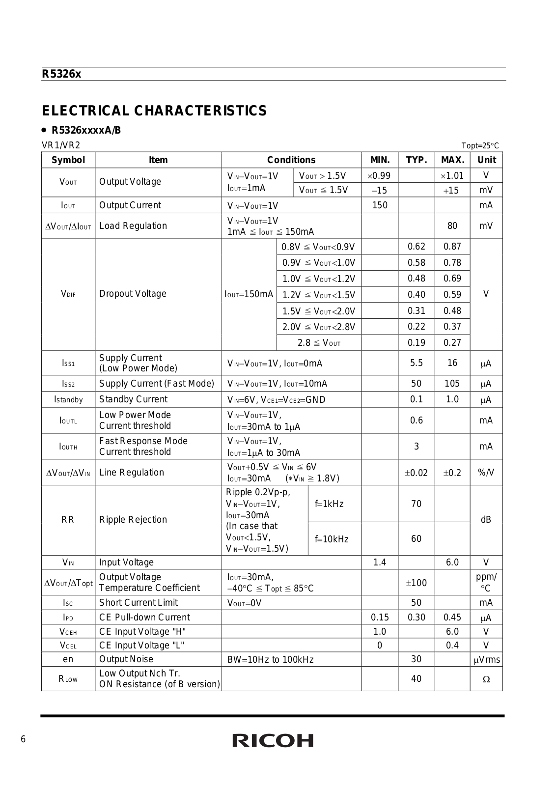
R5326x
R5328K
2
R5400N
R5402N
R5403x
R5405x
R5421N111C-TR
R5421N112C-TR
R5421N151F-TR
R5421N152F-TR
R5422N111C
R5422N111E
R5422N112C
R5422N112E
R5432V
R5433V
R5434D
R5440N201A-TR
R5460x
2
R5461K
R5462K
R5463K
R5470x
R5471x
R5520H
2
R5523N
R5524N
R5533V
R5540K
R5C841
R5RL
R6
7
R7
10
R8
12
RB040001
RB040001a
RB040002
RB040003
RB040004
RB040005
RB040008
RB040009
RB040011
RB040012
RB040013
RB5C634A
rc200
7
RC-210
5
RCP40
2
rcr770
Loading...
Loading...
Nothing found
R5326x
Technical data
27 pgs
500.33 Kb
0
Table of contents
Loading...
RICOH R5326x Technical data
...
RICOH Technical data
Download
Specifications and Main Features
Frequently Asked Questions
User Manual
Download
Loading...
+
hidden pages
Unhide
You need points to download manuals.
1 point = 1 manual.
You can buy points or you can get point for every manual you upload.
Buy points
Upload your manuals
 Loading...