

Page 1
R1204x Series
p
p
T
PWM/VFM Step-up DC/DC Converter for White LED / PMOLED and General Use
The R1204x Series are CMOS-based PWM/VFM step-up DC/DC converters, which are optimized to drive white LEDs and OLED with constant current.
There are two types. The A/D versions are optimized for th e g en eral use or the drive of PMOLED, and the B/ C/ E/F version i s optim ized fo r the serial drive
of white LED with constant current. The R1204x incl udes an under-voltage lockout circuit (UVLO), a soft-start circuit, and an over-voltage protection
circuit (OVP), a thermal shutdown circuit. By simp ly using an inductor, divider resisters, an d capacitors as external co mponents, OLED an d white LED s
can be driven with high efficiently. The A/D version ca n set whit e LED current wit h feedb ack resi ster ( R1). The b rightne ss of the L EDs an d the soft-start
time can be adjusted by apply i ng a PWM s ignal (20 0H z to 30 0kH z) to the CE pi n. In addition to DFN(P LP )1820 -6 , 0 .9 5mm thic kness TSOT-23-6 is available.
FEATURES
• Supply Current (IDD)························
• Standby Current
(I
standby
)
··················Max. 5μA (
• Input Voltage Range (VIN)···············2.3V to 5.5V
• Feedback Voltage
(VFB)
·················0.2V (A/D Version)
• Feedback Voltage Accuracy···········± 10mV (A/D Version)
• Oscillator Frequency (fosc)···············
•
Oscillator Maximum Duty Cycle (Maxduty)
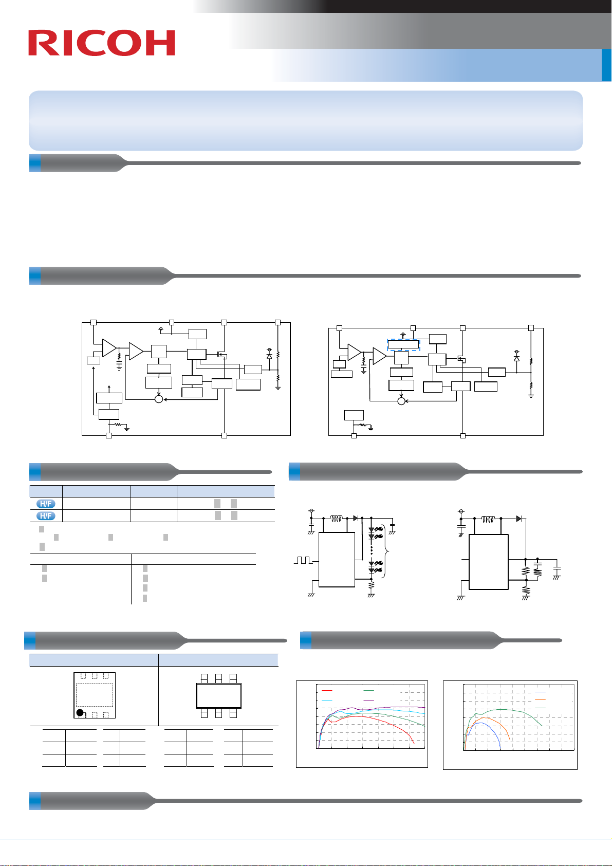
BLOCK DIAGRAMS
R1204xx1xA/D R1204xx1xB/C/E/F
(PWM, V
VFB VIN
Err . Amp .
PWM C omp.
+
+
–
vref
PWM
Cont rol
Shutdown
delay
–
EN
CE
Typ. 800μA (VIN= 5.5V, V
VIN= 5.5V, V
FB
= 0V, Lx at no load)
CE
= 0V
)
1.0V (B/C/E/F Version)
± 15mV (B/C/E/F Version)
1MHz (A/B/C Version), 750kHz (D/E/F Version)
···
Typ. 91% (A/B/C Version), Typ. 92% (D/E/F Version)
RQ
S
Oscillator
Slope Compensation
∑
FB=0.2V) (B/E:PWM, C/F:PWM/VFM auto switching, VFB=1.0V)
Driv er
Cont rol
Current
Limit
Soft-start
UVL O
Current
sense
LX
Thermal
Shutdow n
VOUT
OVP
• UVLO Detect Voltage (VUVLO)·······Typ. 2.0V
• Coil-current Limit Circuit ··············Current Limit Typ. 900mA
•
Over Voltage Protection Circuit (OVP)
···
Typ. 23V, Typ. 33V, Typ. 42V
• Soft Start Time (tstart)·····················Controllable by PWM signal
to the CE pin (A/D Version)
Typ. 10ms (B/C/E/F Version)
• Thermal Shutdown Circuit ···········Stops at 150°C
• Packages·····································
VFB VIN LX
vref
Soft- start
Err. Amp.
+
–
.
PWM Co m
VFM Control
+
RQ
–
S
Oscilla tor
Slope Com-
ensation
∑
CE
DFN(PLP)1820-6, TSOT-23-6
UVL O
Driv er
Cont ro l
Ther mal
Current
Current
Limit
sense
Shutdow n
VOU
OVP
SELECTION GUIDES TYPICAL APPLICATIONS
Halogen Free
.x. : Specify the OVP voltage.
Package
DFN(PLP)1820-6
TSOT-23-6
Q'ty per Reel
5,000 pcs
3,000 pcs
R1204K .x.12.∗ -TR
R1204N
GNDCE
Part No.
.x.13.∗
-TR-FE
Blue Line : only R1204xx1xC/F
2.3V to 5.5V
V
IN
=
C1
(1) OVP : 23V, (2) OVP : 33V, (3) OVP : 42V
:
Specify the control, feedback voltage and oscillator frequency.
.∗
VFB=0.2V VFB=1.0V
PWM, 1MHz
(A)
PWM, 750kHz
(D)
PACKAGES (Top View) TYPICAL CHARACTERISTIC
DFN(PLP)1820-6 TSOT-23-6
6 5 4
∗
1 2 3
1 VOUT 4 VIN
2 LX 5 CE
3 GND 6 VFB
The tab is substrate level (GND).
)
∗
PWM, 1MHz
(B)
PWM/VFM auto switching, 1MHz
(C)
PWM, 750kHz
(E)
PWM/VFM auto switching
(F)
1 LX 4 CE
2 GND 5 VOUT
3 VFB 6 VIN
, 750kHz
6 5 4
1 2 3
L1: 10μH(A) or 22μH(D)
μ
F, C 2 : 1
C1: 1
Efficiency vs. LED Output Current L=22μH (VLF302512MT220)
R1204xx1xD(10 LEDs)
100
95
90
85
80
75
Efficiency [%]
70
65
60
0 5 10 15 20 25 30 35
CE
R1204xx1xA/D
L1
D1
VINL
X
V
OUT
CE
V
FB
GND
R1
μ
F, R1: 10Ω
Vin= 3.2 V Vin= 3.6 V
Vin= 4.2 V Vin= 5 V
Output Current [mA]
C2
V
=
LED
V
-V
to
IN
FB
MIN -3 V
V
OVP1
L1: 10μH(B/C) or 22μH(E/F),
C1: 1
R1: 10kΩ, R2: 240kΩ, R3: 0Ω
R1204xx1xF(VOUT=31V)
GND
R1204xx1xB/C/E/F
V
2.3V to 5.5V
IN
=
L1
C1
V
IN
CE
GND
μ
F, C 2 : 1μF, C3: 10pF,
D1
L
X
V
OUT
V
FB
C3
R2
R3
R1
100
95
90
85
80
75
Effici ency [%]
70
65
60
0 102030405060708090
Output Current [mA]
Vin= 3.2 V
Vin= 3.6 V
Vin= 5 V
C2
APPLICATIONS
• OLED power supply for hand-held equipment • White LED backlight for hand-held equipment
No.EK-284-120522 Step-up DC/DC Converter
Page 2

R1204x Series Step-up DC/DC Converter
PWM/VFM Step-up DC/DC Co nverter for White LED / PMOLED and General Use
R1204x Version Lineup
Product Name R1204xx1xA/D R1204xx1xB/C/E/F
Application White LED (Serial drive) PMOLED, General Use
VFB Voltage 0.2V 1.0V
Comment LED Current setting
The LED current (I
LED) when a ”H” signal is applied to the
CE pin (Duty=100%) can be determined by the value of
feedback resistor (R1).
LED=0.2 / R1
I
LED Dimming Control
The LED brightness can be controlled by inputting the
PWM signal to the CE pin. The current of LEDs when
High-Duty of the CE input is ”Hduty” reaches the value
as in next formula.
LED=Hduty × VFB / R1
I
The frequency of the PWM signal is using the range
between 200Hz to 300kHz. When controlling the LED
brightness by the PWM signal of 20kHz or less, the
increasing or decreasing of the inductor current might
be make a sounds in the hearable sound wave area. In
that case, please use the PWM signal in the high
frequency area.
Soft-Start Time
Unless otherwise V
OUT is beyond the threshold (Vf x
number of LED lights), current will not flow through LEDs,
as a result, V
OUT by controlling the output of error amplifier to “H” and
V
FB voltage will not increase. The IC increases
turning the Lx switch on and off for a certain period of time
(until the current flow). At the mean time, the inrush
current is controlled by gradually increasing the current
limit. If V
OUT is over the threshold (the current flows), the IC
controls the soft-start function by gradually increasing the
reference voltage of error amplifier.
The Method of Output Voltage Setting
Output Voltage= (R1+ R2) / R1
The total value of R1 and R2 should be equal or less than
300kΩ.
Voltage rating of capacitor (C2) is recommended to use 1.5
times or more the output setting voltage.
Soft-Start Time
The IC controls the soft-start function by gradually increasing
the reference voltage of error amplifier. Soft-start begins when
the output voltage of error amplifier is 0V and ends when it
reaches the constant voltage.
The soft start time is set to Typ. 10ms within the IC.
The currently available information as of May 2012 is provided in this New Product News.
EK-284-120522
 Loading...