

Page 1
R1202x Series
y
μ
μ
PWM Step-up DC/DC Converter for White LED / PMOLED and General Use with shutdown function
The R1202x Series are CMOS-based PWM step-up DC/ DC converters, which are opti mized to drive white LEDs and OLED with constant
current. There are two types. The A/B versions are optimized for the general use or the drive of PMOLED, and the D version is optimized
for the serial drive of white LED with constant current. The R1202x includes an under-voltage lockout circuit (UVLO), a s oft-start circuit,
and an over-voltage protection circuit (OVP), a thermal shutdown circuit. By simply using an inductor, divider resisters, and capacitors as
external components, OLED and white LEDs can be driven with high efficien tly. At the standby mode, the internal NPN transistor can
separate the output from the input. (Shutdown function) The A/B version with auto-discharge functio n is selectable. D Version can set
white LED current with feedback resister (R1). The brig htness of the LEDs and the soft-start time can be adjusted by applying a PWM
signal (200Hz to 300kHz) to the CE pin. In addition to DFN1616-6B, 0.95mm thickness TSOT-23-6 is available.
FEATURES
• Supply Current (IDD)························ Typ. 800μA
• Standby Current
(I
standby
)
··················Max. 5μA (
• Input Voltage Range (VIN) ··············· 2.3V to 5.5V (A/B Version)
• Feedback Voltage
(VFB)
·················1.0V (A/B Version)
1.8V to 5.5V (D Version)
0.2V (D Version)
• Feedback Voltage Accuracy··········· ± 1.5% (A/B Version)
• Oscillator Frequency (fosc)···············1.2MHz
± 10mV (D Version)
•
Oscillator Maximum Duty Cycle (Maxduty)
···Typ. 91%
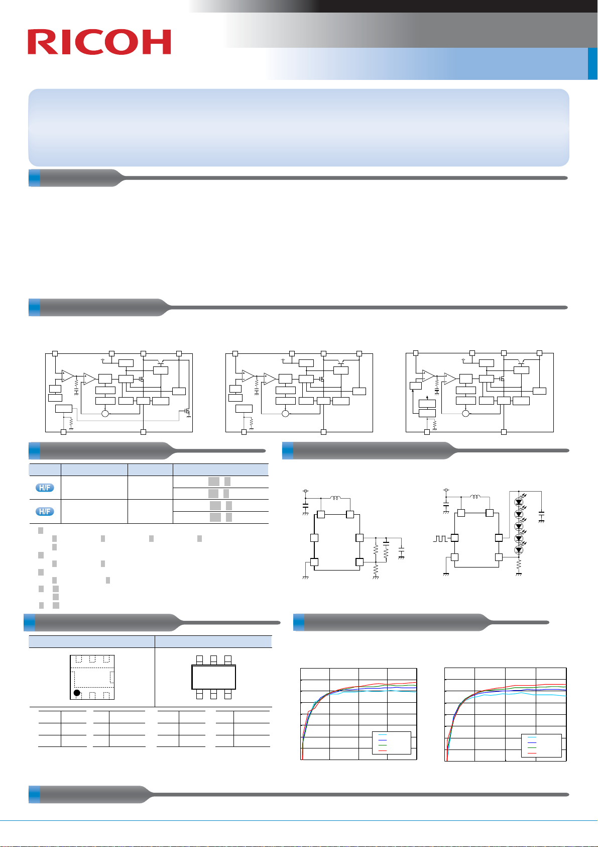
BLOCK DIAGRAMS
(VIN= 5.5V, V
VIN= 5.5V, V
FB
= 0V, Lx at no load)
CE
= 0V
)
• UVLO Detect Voltage (VUVLO)···Typ. 2.0V (A/B Version)
Typ. 1.6V (D Version)
• Coil-current Limit Circuit ··········Current Limit Typ. 350mA
/ Typ. 700mA selectable
• Over Voltage Protection Circuit (OVP)
• Soft Start Time (tstart) ················Typ. 2ms (A/B Version)
Controllable by PWM signal
to the CE pin (D Version)
• Thermal Shutdown Circuit ·······Stops at 150°C
• Auto-Discharge function ··········A Version
• Packages································· DFN1616-6B, TSOT-23-6
R1202xxxxA
(With Auto-Discharge function, VFB=1.0V)
V
FB
Error Amp.
Vref
Soft Start
Chip Enable
CE
SELECTION GUIDES TYPICAL APPLICATIONS
Halogen Free
.x. :
.y.
: Specify the OVP voltage.
(3
.$.
: Specify the Coil Current limit.
(1
: (.A.)
.∗
(.B.)
: (.D.)
#
Package
DFN1616-6B
TSOT-23-6
Specify the OVP voltage.
(3) OVP : 14V, (4) OVP : 17V, (5) OVP : 19V, (6) OVP : 21V
(7) OVP : 23V
) OVP : 14V, (7) OVP : 23V
) Typ. 350mA, (2) Typ. 700mA
with auto-discharge function, VFB=1.0V
without auto-discharge function, VFB=1.0V
without auto-discharge function, VFB=0.2V
PACKAGES (Top View) TYPICAL CHARACTERISTIC
DFN1616-6B TSOT-23-6
6 5 4
1 2 3
1 CE 4 GND
2 VFB 5 VIN
3 LX 6 VOUT
The tab is substrate level (GND).
)
∗
PWM Comp.
R Q
S
OSC
Slope
Compensation
Σ
∗
V
IN
UVLO
Driver
Control
Current
Limit
Q'ty per Reel
5,000 pcs
3,000 pcs
L
X
Current
Sense
GND
Switch
Control
Thermal
Shutdown
V
OUT
OVP
R1202L .x$.1.∗ -TR
R1202L .y$1.#-TR
R1202N
R1202N
1 CE 4 LX
2 VOUT 5 GND
3 VIN 6 VFB
(Without Auto-Discharge function, VFB=1.0V)
V
FB
Error Amp.
Vref
Soft Start
Chip Enable
Part No.
.x$.3.∗
-TR-FE
.y$.3.#
-TR-FE
.
.
.
6 5 4
1 2 3
PWM Comp.
CE
R1202xxxxB
V
IN
L
X
UVLO
Driver
RQ
Control
S
OSC
Slope
Current
Compensation
Limit
Σ
C1
1μF
90
85
80
75
70
65
Efficiency (%)
60
55
50
0 5 10 15 20
Switch
Control
Current
Thermal
Sense
Shutdown
GND
R1202xxxxA/B
L1
H
10
V
IN
L
X
CE
V
OUT
V
GND
FB
R1202N713D Efficiency vs. LED Output Current
4LEDs
Output Current ILED (mA)
V
OUT
OVP
(
10μF
(Without Auto-Discharge function, VFB=0.2V)
V
FB
Error Amp.
Vref
PWM
EN
Cntrl
Shutdown
dela
Chip Enable
C3
R2
R3
R1
CE
C2
F
1
)
Vi n=3V
Vi n=3. 6V
Vi n=4. 2V
Vi n=5V
R1202xxxxD
V
IN
L
X
R Q
S
OSC
Slope
Compensation
Σ
UVLO
Driver
Control
Current
Limit
PWM Comp.
R1202xxxxD
V
IN
CE
GND
L1
10μH
V
C1
1μF
5LEDs (10μF)
90
85
80
75
70
65
Eff icien cy (%)
60
55
50
0 5 10 15 20
Ou tpu t C urr ent ILED (mA )
Switch
Control
Current
Thermal
Sense
Shutdown
GND
L
X
OUT
V
FB
R1
10Ω
V
OUT
OVP
Vin=3V
Vin=3.6V
Vin=4.2V
Vin=5V
C2
0.22μF
APPLICATIONS
• OLED power supply for hand-held equipment • White LED backlight for hand-held equipment
No.EK-255-111001 Step-up DC/DC Converter
Page 2
R1202x Series Step-up DC/DC Converter
μ
μ
PWM Step-up DC/DC Converter for White LED / PMOLED and General Use with shutdown function
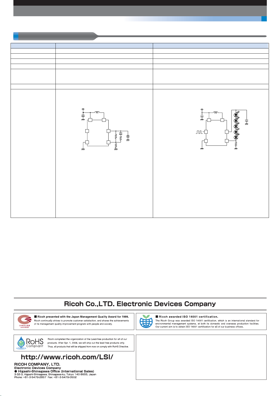
R1202x Version Lineup
Product Name R1202xxxxA/B R1202xxxxD
Application PMOLED, General Use White LED (Serial drive)
VFB Voltage 1.0V 0.2V
Input Voltage Range 2.3V to 5.5V 1.8V to 5.5V
OVP Voltage Select from 14V, 17V, 19V, 21V, 23V Select from 14V, 23V
Function Thermal Shutdown Circuit
Shutdown Function
Auto-Discharge Function
Output Capacitor 1μF to 4.7μF 0.22μF to 1μF
Comment The Method of Output Voltage Setting
Output Voltage= (R1+ R2) / R1
C1
1μF
L1
10μH
VIN LX
CE
VOUT
GND
VFB
C3
C2
1
R2
R1
F
R3
The total value of R1 and R2 should be equal or less
than 300kΩ.
Voltage rating of capacitor (C2) is recommended to
use 1.5 times or more the output setting voltage.
Soft-Start Time
The soft start time is set to Typ. 2ms within the IC.
In case of 6 lights or more, we recommends the R1205x Series and R1218x Series*.
More than 5 lights of R1218x Series requires an external diode and OVP Voltage is set up to 31.5V. (Maximum rating of V
∗) For detail, please check our website.
Thermal Shutdown Circuit
Shutdown Function
LED Current setting
When CE pin input is "H" (Duty=100%), LED current can be set
with feedback resistor (R1).
LED=0.2 / R1
I
C1
1μF
L1
10μH
VIN LX
CE
VOUT
C2
0.22
F
GND
VFB
R1
10Ω
LED Dimming Control
The LED brightness can be controlled by inputting the PWM
signal to the CE pin. The current of LEDs when High-Duty of the
CE input is ”Hduty” reaches the value as in next formula.
LED=Hduty × VFB / R1
I
The frequency of the PWM signal is using the range between
200Hz to 300kHz. When controlling the LED brightness by the
PWM signal of 20kHz or less, the increasing or decreasing of
the inductor current might be make a sounds in the hearable
sound wave area. In that case, please use the PWM signal in
the high frequency area.
OUT pin is 34V)
The currently available information as of October 2011 is provided in this New Product News.
EK-255-111001
 Loading...