

Page 1

LCT
(Machine Code: A862/B391)
Page 2

10 August, 2001 SPECIFICATIONS
1. OVERALL MACHINE INFORMATION
1.1 SPECIFICATIONS
Paper Size:
Paper Weight: 60 g/m2 ~ 105 g/m2, 16 lb ~ 28 lb
Tray Capacity: 2,000 sheets (80 g/m2, 20lb)
Remaining Paper Detection: 5 steps (100%, 75%, 50%, 25%, Near end)
Power Source: 24 Vdc, 5 Vdc (from copier/printer)
Power Consumption: 26 W (Max.)/14 W (Ave.)
Weight: 25 kg (55 lbs)
Size (W x D x H): 550 mm x 520 mm x 271 mm
A4 sideways/LT sideways
B391-1
Options
Page 3
MECHANICAL COMPONENT LAYOUT 10 August, 2001
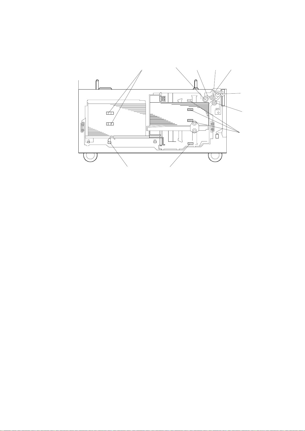
1.2 MECHANICAL COMPONENT LAYOUT
1. Pick-up Roller
10
2143
5
6
7
89
B391D101.WMF
7. Paper Height Sensors 1, 2, 3
2. Upper Limit Sensor
3. Paper Feed Roller
4. Relay Sensor
5. Relay Roller
6. Reverse Roller
8. Lower Limit Sensor
9. Left Paper End Sensor
10. Paper Height Sensors 4,5
B391-2
Page 4
10 August, 2001 ELECTRICAL COMPONENT LAYOUT
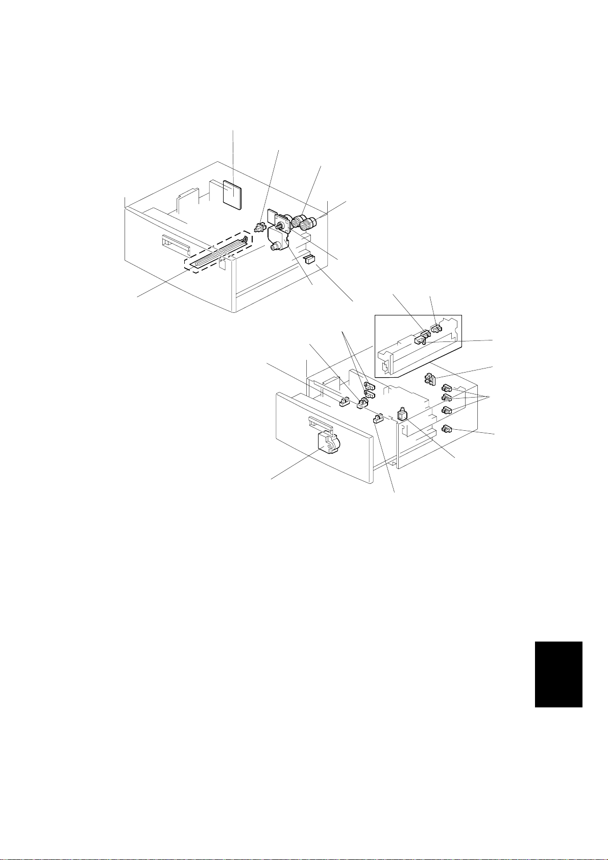
1.3 ELECTRICAL COMPONENT LAYOUT
1
2
3
4
5
7
B391D102.WMF
1. Main Board
2. Tray Sensor
17
16
6
89
20
19
18
B391D103.WMF
15
12. Paper Height Sensors 1, 2, 3
13. Lower Limit Sensor
10
11
12
13
14
3. Relay Clutch
4. Paper Feed Clutch
5. Tray Motor
6. Tray Lift Motor
7. Tray Heater (option)
8. Right Tray Paper End Sensor
9. Upper Limit Sensor
10. Relay Sensor
11. Side Fence Open/Closed Sensors
B391-3
14. Side Fence Solenoid
15. Rear Fence Return Sensor
16. Rear Fence Motor
17. Rear Fence Home Position
Sensor
18. Left Tray Paper End Sensor
19. Paper Height Sensors 4, 5
20. Right Cover Switch
Options
Page 5

ELECTRICAL COMPONENT DESCRIPTIONS 10 August, 2001
1.4 ELECTRICAL COMPONENT DESCRIPTIONS
Symbol Name Function Index No.
Motors
M1 Tray Motor Drives all rollers. 5
M2 Tray Lift Motor Drives the paper tray up or down. 6
Rear Fence
M3
Sensors
S1
S2
S3
S4
S5
S6
S7
S8 Tray Detects whether the tray is correctly set. 2
S9
S10
S11
Solenoids
SOL1
Magnetic Clutches
MC1 Paper Feed Drives the paper feed roller. 4
MC2 Relay Drives the relay roller. 3
PCBs
PCB1
Switches
SW1 Right Cover Detects whether the right cover is open. 20
Motor
Right Tray
Paper End
Relay
Upper Limit Detects when the paper is at the correct
Lower Limit Detects when the tray is completely lowered,
Paper Height
1, 2, 3
Paper Height
4, 5
Rear Fence
Home Position
Side Fence
Open/Closed
Rear Fence
Return
Left Tray
Paper End
Side Fence Contro ls open-close movement of the side
Main Controls the LCT and communicates with the
Moves the rear fence to transfer the paper
stack from the paper storage (left) side of the
tray to the paper feed (right) side.
Informs the copier/printer when the paper in
the right side (paper feed side) of the tray has
been used up. If there is a paper stack in the
left side (paper storage side), this is moved
into the right tray. If there is no paper stack in
the left side, paper end is indicated.
Detects the copy paper coming to the relay
roller and checks for misfeeds.
paper feed height.
to stop the LCT motor.
Detects the amount of paper remaining in the
right side of the tray.
Detects the amount of paper remaining in the
left side of the tray.
Detects when the rear fence is at H.P.
Detects whether the side fence is opened on
closed.
Detects when the rear fence has moved the
paper stack from the left side to the right side.
Informs the copier/printer when there is no
paper in the left side (paper storage side) of
the tray.
fence.
copier/printer.
16
8
10
9
13
12
19
17
11
15
18
14
1
B391-4
Page 6
10 August, 2001 PAPER FEED
2. DETAILED SECTION DESCRIPTIONS
2.1 PAPER FEED
[B]
[A]
[C]
B391D104.WMF
This products uses an FRR type paper feed mechanism.
The paper feed unit consists of the pickup roller [A], paper feed roller [B], reverse
roller [C], and grip and transport rollers.
There is a torque limiter in the back of the reverse roller (ferrite powder type).
B391-5
Options
Page 7

REVERSE ROLLER AND PICK-UP ROLLER RELEASE 10 August, 2001
2.2 REVERSE ROLLER AND PICK-UP ROLLER RELEASE
[A]
[E]
[C]
[B]
B391D107.WMF
[E]
[A]
[D]
B391D108.WMF
To prevent the paper from being torn when pulling out the paper feed tray, the
reverse and pickup rollers are set so that they release automatically.
When the paper tray [A] is not inside the machine, the reverse rolle r [B] is away
from the paper feed roller [C] and the pick-up roller [D] stays in the upper position.
When the paper tray is set into the machine, it pushes the release lever [E]. This
causes the pick-up roller [D] to go down into contact with the top sheet of paper
and the reverse roller [B] to move up and contact the paper feed roller.
B391-6
Page 8

10 August, 2001 TRAY LIFT
2.3 TRAY LIFT
[F]
[G]
[A]
[E]
B391D110.WMF
[B]
[D]
[C]
When the paper feed tray is put in the machine, the tray switc h [A] on the back face
turns on and the tray lift motor [B] starts up. The base plate lift shaft [C] is coupled
to the lift motor at shaft [D], so the base plate of the tray is lifted. After a short while,
the top of the paper stack contacts the pick-up roller and lifts it up.
When this occurs, the actuator enters the upper limit sensor, the sensor turns off
and the lift motor stops. When paper in the tray is used up, the pick-up roller is
gradually lowered, and the actuator leaves the upper limit sensor (turning the
sensor on). When this happens, the lift motor begins turning again. The tray will
then be lifted until the actuator enters the upper limit sensor (turning the sensor off
again).
When the tray is removed from the copier, the coupling between the lift motor [B]
and base plate lift shaft [C] is broken and the base plate goes into a controlled free
fall (using a damper [E] to slow the fall and prevent damage).
B391-7
Options
Page 9

NEAR END/END DETECTION 10 August, 2001
2.4 NEAR END/END DETECTION
This tray can hold two stacks of paper, so the machine needs to monitor the status
of both these stacks. There are seven sensors to do this.
In the right tray (paper feed side), three height sensors measure the height of the
stack, and an end sensor detects when all the paper is used up. As the amount of
paper remaining in the tray decreases, the base plate rises and the actuator
activates the paper height sensors. When paper runs out in the right tray, the stack
in the left tray is moved across to the right tray.
There are also two height sensors ([F] in the diagram on the previous page) and an
end sensor in the left tray (paper storage side) ([G] in the diagram on the previous
page). When there is no paper in both trays, paper end is detected.
The machine determines the amount of remaining paper based on the sensor
outputs, as shown in the following table.
Paper end sensor 1: ❍ = Low (no paper), # = High (paper present)
Other sensors: ❍ = Low (paper present), # = High (no paper)
Amount of paper
100% 75% 50%
Paper Height Sensor 1
Paper Height Sensor 2
Paper Height Sensor 3
Paper End Sensor 1
Paper Height Sensor 4
Paper Height Sensor 5
Paper End Sensor 2
Paper Height Sensor 1
Paper Height Sensor 2 – –
Paper Height Sensor 3 – – –
Paper End Sensor 1
Paper Height Sensor 4
Paper Height Sensor 5
Paper End Sensor 2
❍❍ ❍ ❍❍ ❍ # ❍ ❍
❍❍ ❍ ❍❍ #
❍❍ # ❍ ❍
## # ## # # # #
❍# ❍ ## ❍ ❍ # #
❍❍ ❍ ## ❍ ❍ ❍ ❍
❍❍ ❍ ❍# ❍ ❍ ❍ ❍
Amount of paper
25% Near-end End
#❍ ❍ ❍❍ # #
#❍#
#
## # ## # # ❍
❍# # ## # # #
#❍ # ## # # #
❍❍ ❍ ## ❍ # #
––––
––
–––
–
The following diagram is the sensor layout, as viewed from the front.
Paper Storage Side Paper Feed Side
Paper Height
Sensor 1
Paper Height
Sensor 5
Paper Height
Sensor 2
Paper End
Sensor 1
❍#
#
–
–
Paper Height
Sensor 4
Paper End
Sensor 2
Paper Height
Sensor 3
B391-8
B391D112.WMF
Page 10

10 August, 2001 RIGHT TRAY SIDE FENCE
2.5 RIGHT TRAY SIDE FENCE
[B]
[C]
[D]
[A]
[E]
[F]
[H]
B391D109.WMF
[G]
When the paper in the right tray is used up, the side fence solenoid [F] activates
and stays on until the side fence open/closed sensor [E] detects that the fence is
open. The rear fence [A] then moves the stack of paper from the left tray into the
right tray, as described in the following section. When the stack has been
transferred to the right tray, the rear fence return sensor [G] detects the rear fence
and then the cpu turns off the side fence open solenoid (closing the side fence).
The side fence open/closed sensor [D] detects when the side fence is closed.
When it is not closed, the user is prompted at the operation panel to free the
mechanism.
2.6 LEFT TRAY REAR FENCE
If the right tray paper end sensor detects that there is no paper in the tray (while
the left tray sensor detects that there is still paper in the left tray), the right side
fence [C] opens and the rear fence motor [H] turns on. The rear fence of the left
tray moves and the paper stack is then transferred from the left tray to the right
tray.
When the left tray rear fence activates the rear fence return sens or, the machine
detects that the paper stack has been transferred to the right tray and the rear
fence motor rotates in the opposite direction. When the rear fence HP sensor [B]
comes on, the motor stops.
B391-9
Options
Page 11

RIGHT TRAY PAPER END DETECTION 10 August, 2001
2.7 RIGHT TRAY PAPER END DETECTION
[A]
[B]
[C]
B391D106.WMF
[E]
[D]
B391D111.WMF
The paper end sensor [A] detects when copy paper in the right tray runs out.
When there is paper in the tray, the paper pushes up the paper end f eeler [B] an d
causes the actuator to come between the LED and photo diode of the sensor.
When paper runs out, the feeler drops and the actuator leaves the photointerruptor,
and the machine detects that there is no paper in the tray.
When the tray is being pulled ou t, the lever [E] lifts the pick-up roller and this also
lifts up the feeler.
B391-10
Page 12

10 August, 2001 DETACHING THE TRAY FROM THE MAINFRAME
3. REPLACEMENT AND ADJUSTMENT
3.1 DETACHING THE TRAY FROM THE MAINFRAME
While pressing the stopper attached to the
guide rail, pull out the large capacity tray.
NOTE: When reinstalling the tray, set the
tray on the guide rail and carefully
push the tray in, making sure to keep
the tray level.
[A]
B391R101.WMF
3.2 REAR FENCE HP SENSOR
LT
1. Pull out the large capacity tray.
2. Remove the left tray rear side fence [A] (2 screws).
3. Remove the rear fence bracket [B] (1 screw).
A4
[C]
[B]
B391R102.WMF
[A]
4. Remove the connector of the rear fence HP sensor.
5. Replace the rear fence HP sensor [C] (1 screw).
NOTE: When securing the sensor in place, be sure to fasten the screw in the
proper position.
B391-11
Options
Page 13

CHANGING THE TRAY PAPER SIZE 10 August, 2001
3.3 CHANGING THE TRAY PAPER SIZE
[A]
[B]
B391R103.WMF
1. Remove the screws of all side fences [A], [B].
2. The position of the rear fence HP sensor can then be changed (see Rear
Fence HP Sensor Removal).
3. The paper size display can then be changed with an SP mode.
NOTE: When securing the right tray side fence, fasten the screw after setting the
paper in the right tray and adjusting the fence to the width of the paper.
3.4 LEFT TRAY PAPER END SENSOR
[C]
[A]
[B]
B391R104.WMF
1. Pull out the large capacity tray.
2. Remove the left tray side fence [A] (2 screws).
3. Remove the rear fence bracket [B] (1 screws).
4. Replace the left tray paper end sensor [C] (1 connector).
B391-12
Page 14

10 August, 2001 TRAY LIFT MOTOR
3.5 TRAY LIFT MOTOR
[A]
B391R105.WMF
[B]
1. Remove the brackets (1 screw for each).
2. Remove the rear cover [A] (2 screws).
3. Remove the tray lift motor [B] (3 screws, 1 connector).
B391R106.WMF
Options
B391-13
Page 15

TRAY MOTOR 10 August, 2001
3.6 TRAY MOTOR
[A]
[C]
[B]
1. Remove the rear cover.
2. Remove bracket #1 [A] (2 screws).
3. Remove bracket #2 [B] (2 screws).
4. Remove the tray motor [C] (6 screws, 1 connector).
B391R107.WMF
B391-14
Page 16

10 August, 2001 PAPER FEED CLUTCH AND RELAY CLUTCH
3.7 PAPER FEED CLUTCH AND RELAY CLUTCH
[A]
[D]
[B]
[C]
B391R108.WMF
1. Remove the rear cover.
2. Remove bracket #1 [A] (2 screws).
3. Remove bracket #2 [B] (2 screws).
4. Remove all bushings.
5. Remove the paper feed clutch [C] and relay clutch [D].
6. Replace the required clutch.
NOTE: Make sure to properly secure both clutches before completing installation.
B391-15
Options
Page 17

PAPER FEED UNIT 10 August, 2001
3.8 PAPER FEED UNIT
[A]
[B]
[C]
B391R109.WMF
[E]
B391R110.WMF
[D]
1. Remove the paper feed clutch and relay clutch (see Paper Feed Clutch and
Relay Clutch Replacement).
2. Remove pulleys A [A], B [B], and C [C].
3. Remove the paper feed harness from the main board.
4. Open the vertical transport guide plate [D].
5. Remove the paper feed unit [E] (2 screws).
B391-16
Page 18

10 August, 2001 UPPER LIMIT, RIGHT TRAY PAPER END, AND RELAY SENSORS
3.9 UPPER LIMIT, RIGHT TRAY PAPER END, AND
RELAY SENSORS
[A]
[B]
[D]
[C]
B391R111.WMF
1. Remove the paper feed unit (see Paper Feed Unit Replacement).
2. Replace the required sensor.
• Upper limit [A]
• Relay [B]
• Right tray paper end [C]
NOTE: When replac ing the upper limit [A] and pape r end sensor [C], please be
sure to do so while pushing the release lever [D].
Options
B391-17
Page 19

REAR FENCE MOTOR 10 August, 2001
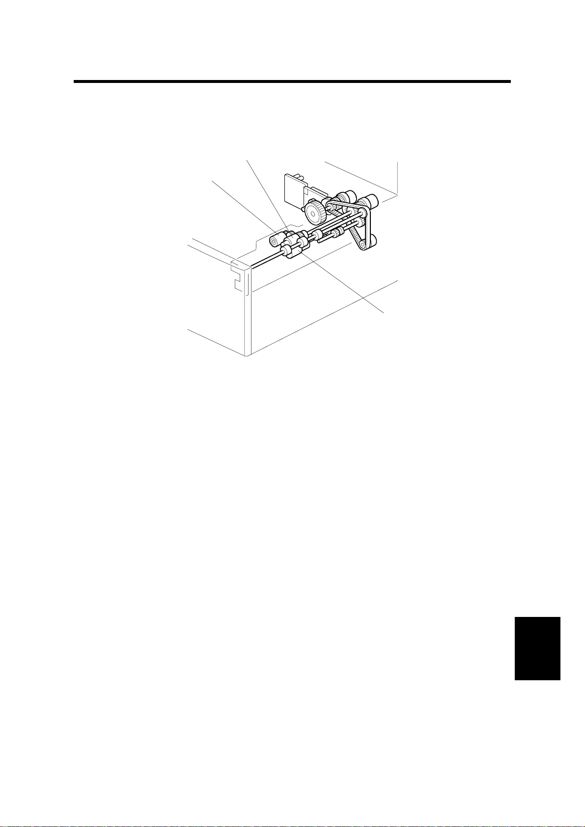
3.10 REAR FENCE MOTOR
[A]
[B]
[H]
B391R112.WMF
[G]
[F]
[E]
[C]
[D]
B391R113.WMF
B391R114.WMF
1. Pull out the paper feed tray unit.
2. Remove the paper feed tray front cover [A] (2 screws).
3. Remove the left side fence [B].
4. Remove the rear fence drive gear [C] (1 screw). This is in order to free the end
fence [D].
5. Move the end fence to the right (toward the center).
6. Remove the end fence (1 screw).
7. Remove the end fence bracket [E] (2 screws).
8. Remove the bracket [F] (1 screw).
9. Remove the bracket [G] of the rear fence motor assembly (2 screws).
10. Remove the rear fence motor assembly (2 screws).
11. Replace the motor [H] (1 connector).
B391-18
Page 20

10 August, 2001 PICK-UP/ PAPER FEED/REVERSE ROLLERS
3.11 PICK-UP/PAPER FEED/REVERSE ROLLERS
[C]
[A]
[B]
B391R115.WMF
1. Remove the paper tray unit (see Paper Tray Unit Replacement).
2. Remove the sna p ring (1 each for the paper feed and reverse rollers).
3. Remove the pick up roller [A].
4. Replace each roller [B], [C].
NOTE: Install the paper feed rollers the correct way round, as shown in the
illustration. If the rollers are installed incorrectly, this will cause the one-way
clutch to lock.
B391-19
Options
 Loading...