

Page 1

PAPER TRAY UNIT
(Machine Code: A860/B390)
Page 2

10 August, 2001 SPECIFICATIONS
1. OVERALL MACHINE INFORMATION
1.1 SPECIFICATIONS
Paper Size:
Paper Weight: 60 ~ 105 g/m2, 16 ~ 28 lbs.
Tray Capacity: 500 sheets (80 g/m2, 20 lbs.) x 2 trays
Paper Feed System: Feed roller and friction pad
Paper Height Detection: 4 steps (100%, 70%, 30%, Near end)
Power Source: 24 VDC, 5 VDC (from the copier/printer)
Power Consumption: Max: 30 W (Copying/printing)
Weight: 25 kg (55 lbs)
A5 to A3
HLT lengthwise to DLT
120 Vac:
120 V version, from the copier/printer when the
optional tray heater is installed
220 ~ 240 Vac:
230 V version, from the copier/printer when the
optional tray heater is installed
23 W (Optional Tray Heater On)
Average: 17 W (Copying/pr inting)
15 W (Optional Tray Heater On)
Size (W x D x H): 550 mm x 520 mm x 271 mm
Options
B390-1
Page 3
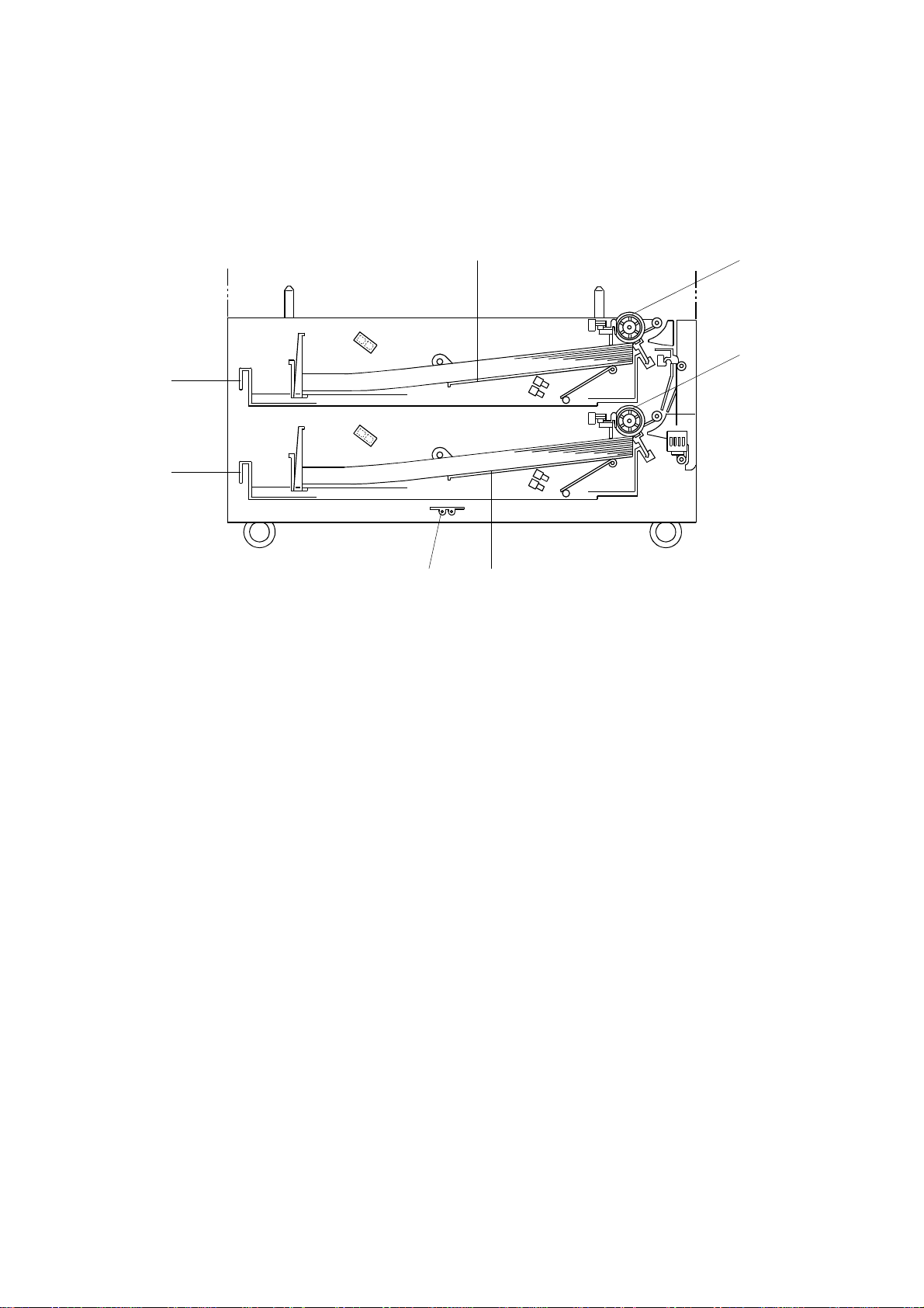
MECHANICAL COMPONENT LAYOUT 10 August, 2001
1.2 MECHANICAL COMPONENT LAYOUT
5
1
2
3
4
67
B390V101.WMF
1. Upper paper feed roller
2. Lower paper feed roller
3. Upper tray
4. Lower tray
5. Upper bottom plate
6. Lower bottom plate
7. Optional tray heater
B390-2
Page 4
10 August, 2001 ELECTRICAL COMPONENT LAYOUT
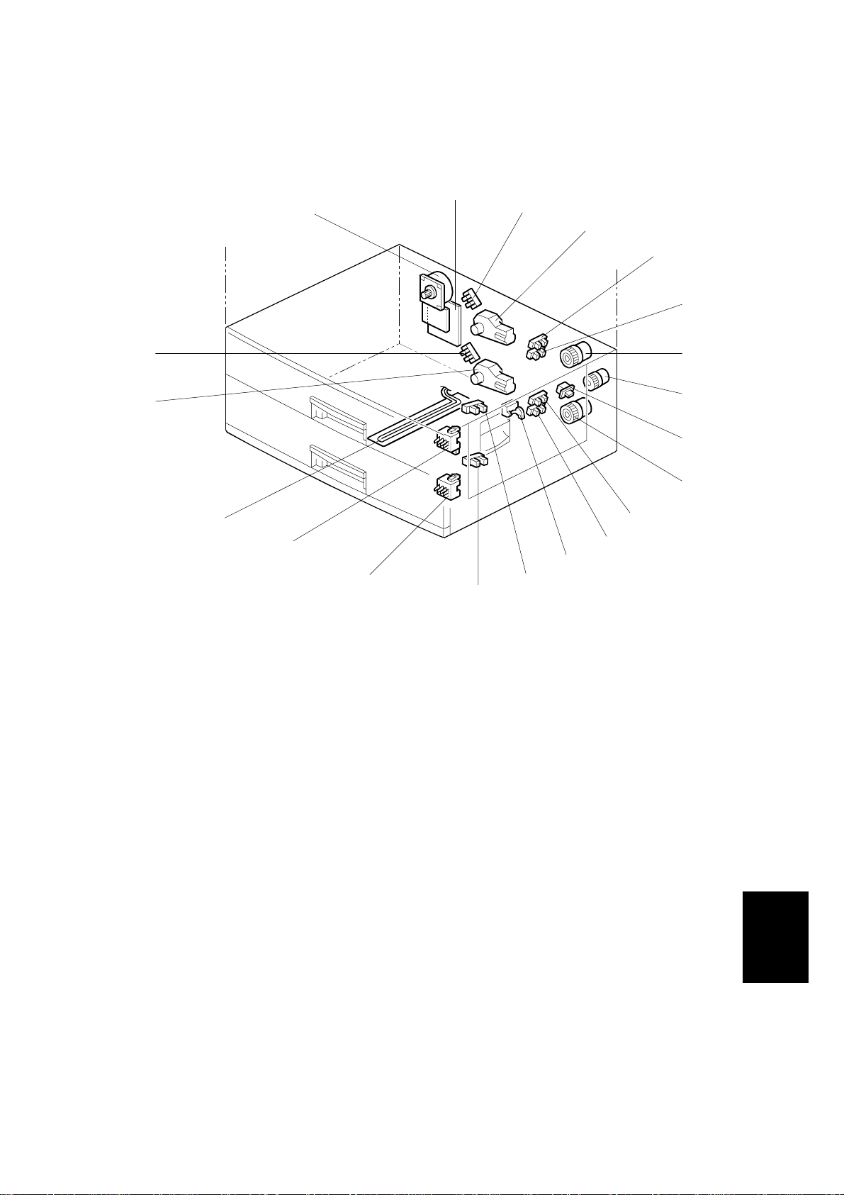
1.3 ELECTRICAL COMPONENT LAYOUT
19
18
17
16
20
15
1
2
3
4
5
6
7
8
9
10
11
12
13
14
B390V102.WMF
1. Tray main board
2. Upper lift sensor
3. Upper lift motor
4. Upper paper height 2 sensor
5. Upper paper height 1 sensor
6. Upper paper feed clutch
7. Relay clutch
8. Tray cover switch
9. Lower paper feed clutch
10. Lower paper height 2 sensor
11. Lower paper height 1 sensor
12. Vertical transport sensor
13. Upper paper end sensor
14. Lower paper end sensor
15. Lower paper size switch
16. Upper paper size switch
17. Optional tray heater
18. Lower lift motor
19. Lower lift sensor
20. Tray motor
Options
B390-3
Page 5

ELECTRICAL COMPONENT DESCRIPTION 10 August, 2001
1.4 ELECTRICAL COMPONENT DESCRIPTION
Symbol Name Function Index No.
Motors
M1 Tray Drives all rollers. 20
M2 Upper Lift Lifts the upper tray bottom plate. 3
M3 Lower Lift Lifts the lower tray bottom plate. 18
Sensors
S1
S2
S3
S4
S5 Vertical Transport Detects misfeeds. 12
S6
S7
S8
S9
Upper Lift Detects when the paper in the upper tray is at
the correct feed height.
Lower Lift Detects when the paper in the lower tray is at
the correct feed height.
Upper Paper End Informs the copier/printer when the upper tray
runs out of paper.
Lower Paper End
Upper Paper
Height 1
Upper Paper
Height 2
Lower Paper
Height 1
Lower Paper
Height 2
Informs the copier/printer when the lower tray
runs out of paper.
Detects the amount of paper in the upper tray.
Detects the amount of paper in the upper tray.
Detects the amount of paper in the lower tray.
Detects the amount of paper in the lower tray.
2
19
13
14
5
4
11
10
Switches
SW1 Tray Cover Detects whether the tray cover is opened or not. 8
SW2 Upper Paper Size Determines what paper size is in the upper tray. 15
SW3 Lower Paper Size Determines what paper size is in the lower tray. 16
Magnetic Clutches
MC1
MC2
MC3 Relay Drives the relay rollers. 7
PCBs
PCB1
Others
H1
Upper Paper
Feed
Lower Paper
Feed
Tray Main Controls the paper tray unit and communicates
Optional Tray
Heater
Starts paper feed from the upper tray.
Starts paper feed from the lower tray.
with the copier/printer.
Removes humidity from the paper in the trays.
6
9
1
17
B390-4
Page 6
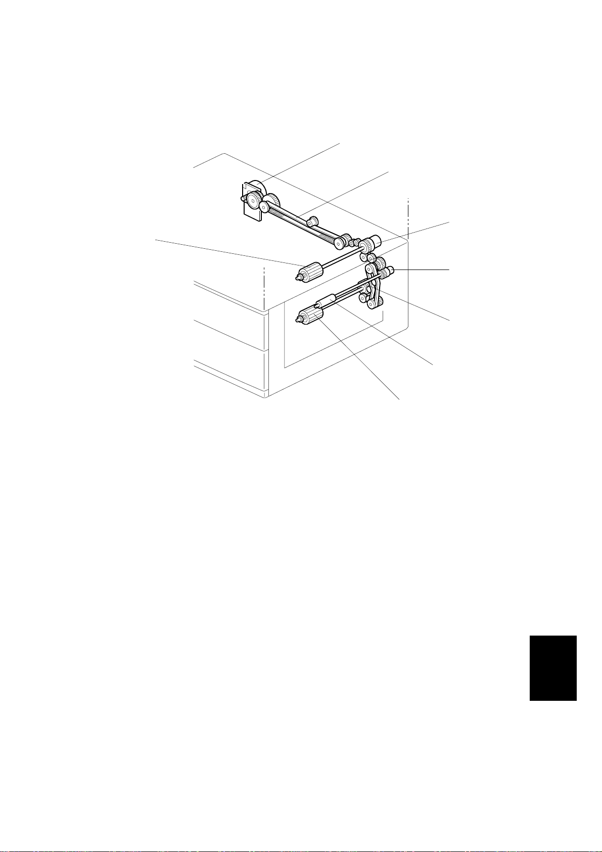
10 August, 2001 DRIVE LAYOUT
1.5 DRIVE LAYOUT
1
2
3
8
4
5
1. Tray motor
2. Drive belt
3. Upper paper feed clutch
4. Relay clutch
6
7
B390V103.WMF
5. Lower paper feed clutch
6. Relay roller
7. Lower paper feed roller
8. Upper paper feed roller
B390-5
Options
Page 7
PAPER FEED AND SEPARATION MECHANISM 10 August, 2001
2. DETAILED DESCRIPTIONS
2.1 PAPER FEED AND SEPARATION MECHANISM
[A]
The paper tray holds 500 sheets. The paper feed roller [A] drives the top sheet of
paper from the paper tray to the copier/printer. The friction pad [B] allows only one
sheet to feed at a time. The friction pad applies pressure to the feed roller with a
spring [C].
[B]
[C]
B390D104.WMF
B390-6
Page 8

10 August, 2001 PAPER LIFT MECHANISM
2.2 PAPER LIFT MECHANISM
[B]
[A]
[D]
[C]
B390D106.WMF
[H]
[E]
[C]
[D]
[E]
The paper size switch detects when the tray is pushed in.
[K] [G]
[F]
[A]
[B]
[I]
[J]
B390D107.WMF
When the paper tray is pushed into the machine, the pin [A ] for the lift motor
pressure shaft engages the lift motor coupling [B] and the pin [C] for the bottom
plate lift shaft in the tray engages the bottom plate pressure lever coupling [D]. The
pin [E] on the rear of the tray pushes the lock lever so that the lift motor can lift the
bottom plate pressure lever.
The lift motor turns on, and turns clockwise as viewed on the diagram. The main
pressure spring [K] pulls the bottom plate pressure lever, and this lifts the tray
bottom plate.
When the top of the stack touches the feed roller, the motor cannot pull up the
plate any more, so it pulls the actuator [G] into the lift sensor [F].
The pressure of the feed roller on the paper is now too high, so the lift motor
reverses to reduce this pressure. It reverses for 300 ms or 600 ms, depending on
the paper size. For smaller paper, it reverses the larger amount (600 ms) to reduce
the pressure more.
B390-7
Options
Page 9

PAPER LIFT MECHANISM 10 August, 2001
The paper size thresholds for this feature depend on SP1-908-8, 9, 17, and 18.
(Note that there are two paper size thresholds for each tray: small and middle.
Some models only use the small threshold.) The amount of reverse depends on SP
1-908-1, 2, 3, 10, 11, and 12. (See the table later in this section for details of how
these SP modes work.)
For A4-width paper or wider, a projection [H] on the side fence engages the
secondary pressure spring [J] through a lever [I] . Then, the secondary pressure
spring [J] applies paper feed pressure in addition to the main pressure spring [K], to
ensure that extra pressure is applied to wider paper.
As stated earlier, various SP modes control this mechanism. The following table
summarizes them.
No Middle Size Programmed
(Default for A250)
Paper width:
Tray 1: More than 1-908-8
Tray 2: More than 1-908-17
(Default: Wider than HLT)
Amount of reverse:
Tray 1: 1-908-1
Tray 2: 1-908-10
(Default 300 ms)
Paper width:
Tray 1: 1-908-8 or less
Tray 2: 1-908-17 or less
(Default: HLT or narrower)
Amount of reverse:
Tray 1: 1-908-2
Tray 2: 1-908-11
(Default: 600 ms)
With Middle Size Programmed
Paper width:
Tray 1: More than 1-908-9
Tray 2: More than 1-908-18
Amount of reverse:
Tray 1: 1-908-1
Tray 2: 1-908-10
Paper width:
Tray 1: More than 1-908-8, up to
and including 1-908-9
Tray 2: More than 1-908-17, up to
and including 1-908-18
Amount of reverse:
Tray 1: 1-908-3
Tray 2: 1-908-12
Paper width:
Tray 1: 1-908-8 or less
Tray 2: 1-908-17 or less
Amount of reverse:
Tray 1: 1-908-2
Tray 2: 1-908-11
When the paper tray is pulled ou t, the pins [A, C] disengage from the couplings [B,
D], and the bottom plate drops. To make it easier to push the tray in, the lift motor
rotates backwards 1.7 seconds to return the bottom plate pressure lever coupling
[D] to the original position.
B390-8
Page 10

10 August, 2001 PAPER END DETECTION
2.3 PAPER END DETECTION
[A]
[B]
[C]
B390D105.WMF
If there is some paper in the paper tray, the paper stack raises the paper end feeler
[A] and the paper end sensor [B] is deactivated.
When the paper tray runs out of paper, the paper end feeler drops into the cutout
[C] in the tray bottom plate and the paper end sensor is activated.
When the paper tray is drawn out with no paper in the tray, the shape of the paper
end feeler causes it to lift up.
Options
B390-9
Page 11

PAPER HEIGHT DETECTION 10 August, 2001
2.4 PAPER HEIGHT DETECTION
[B]
[A]
[C]
[C]
B390D107.WMF
The amount of paper in the tray is detected by the combination of on/off signals
from two paper height sensors [A] and [B].
When the am ount of pape r decreases, the bottom pl ate pressure lever [C] moves
the actuator up.
The following combination of sensor signals is sent to the copier/printer.
Amount of Paper Paper Height Sensor 1 Paper Height Sensor 2
Near End OFF ON
30% ON ON
70% ON OFF
100% OFF OFF
When the tray contains paper of a small width, the paper feed pressure may
become too low when the thickness of the remaining stack of paper has
decreased. The lift motor rotates forward 300 ms after the sensor detects a certain
amount of paper remaining in the tray to increase paper feed pressure, simulating
the pressure generated by a full tray.
B390-10
Page 12

10 August, 2001 PAPER HEIGHT DETECTION
The amount of remaining paper depends on SP modes 1-908-6, 7, 15, and 16. The
amount of forward rotation depends on SP1-908-4, 5, 13, and 14. Note that there
are two paper size thresholds for each tray: small and middle (this is the same as
for the paper lift mechanism described earlier). Some models only use the small
threshold. The paper size thresholds depend on SP1-908-8, 9, 17, and 18.
The following table summarizes how these SP modes work.
No Middle Size Programmed
(Default for A250)
Paper width:
Tray 1: More than 1-908-8
Tray 2: More than 1-908-17
(Default: Wider than HLT)
Amount of forward rotation:
None
Paper width:
Tray 1: 1-908-8 or less
Tray 2: 1-908-17 or less
(Default: HLT or narrower)
Amount of remaining paper:
Tray 1: 1-908-6
Tray 2: 1-908-15
(Default: When near-end is
detected)
Amount of forward rotation:
Tray 1: 1-908-4
Tray 2: 1-908-13
(Default: 300 ms)
With Middle Size
Programmed
Paper width:
Tray 1: More than 1-908-9
Tray 2: More than 1-908-18
Amount of forward rotation:
None
Paper width:
Tray 1: More than 1-908-8, up
to and including 1-908-9
Tray 2: More than 1-908-17, up
to and including 1-908-18
Amount of remaining paper:
Tray 1: 1-908-7
Tray 2: 1-908-16
Amount of forward rotation:
Tray 1: 1-908-5
Tray 2: 1-908-14
Paper width:
Tray 1: 1-908-8 or less
Tray 2: 1-908-17 or less
Amount of remaining paper:
B390-11
Tray 1: 1-908-6
Tray 2: 1-908-15
Amount of forward rotation:
Tray 1: 1-908-4
Tray 2: 1-908-13
Options
Page 13

PAPER SIZE DETECTION 10 August, 2001
2.5 PAPER SIZE DETECTION
Size
1/2
1/2
1/2
" x 14"
" x 11"
1/2
" x 13")
"
A3, F (8
A4 Lengthwise
A4 Sideways
A5 Sideways,
11" x 17"
B4, 8
B5 Sideways,
8
B5 Lengthwise,
11" x 8
* (Asterisk)
SW
1234
!!!
!
❍
!
❍❍❍
!!
!
❍
❍❍❍❍
❍❍
❍❍
!
: ON (Not pushed)
❍: OFF (Pushed)
❍
!
❍
❍❍
❍❍
!
❍
!!
[B]
[A]
B390D108.WMF
There are four paper size microswitches [A] on the front right plate of the paper tray
unit. The switches are actuated by a paper size actuator [B] behind the paper size
indicator plate, which is on the front right of the tray.
Each paper size has its own actuator, with a unique combination of notches. To
determine which size has been installed, the CPU reads which microswitches the
actuator has switched off.
The CPU disables paper feed from a tray if the paper size cannot be detected. If
the paper size actuator is broken, or if there is no tray installed, the Add Paper
indicator will light.
When the paper size actuator is at the “*” mark, the paper tray can be set up to
accommodate one of a wider range of paper sizes by using user tools. If the paper
size for this position is changed without changing the user tool setting, a paper jam
will result.
B390-12
Page 14

10 August, 2001 SIDE AND END FENCES
2.6 SIDE AND END FENCES
[A]
[D]
[B]
B390D110.WMF
[C]
B390D109.WMF
Side Fences
If the tray is full of paper and it is pushed in strongly, the fences may deform or
bend. This may cause the paper to skew or the side-to-side registration to be
incorrect. To correct this, each side fence has a stopper [A] attached to it. Each
side fence can be secured with a screw [B], for customers who do not want to
change the paper size.
End Fence
As the amount of paper in the tray decreases, the bottom plate [C] lifts up
gradually. The end fence [D] is connected to the bottom plate. When the tray
bottom plate rises, the end fence moves forward and pushes the back of the paper
stack to keep it squared up.
B390-13
Options
Page 15

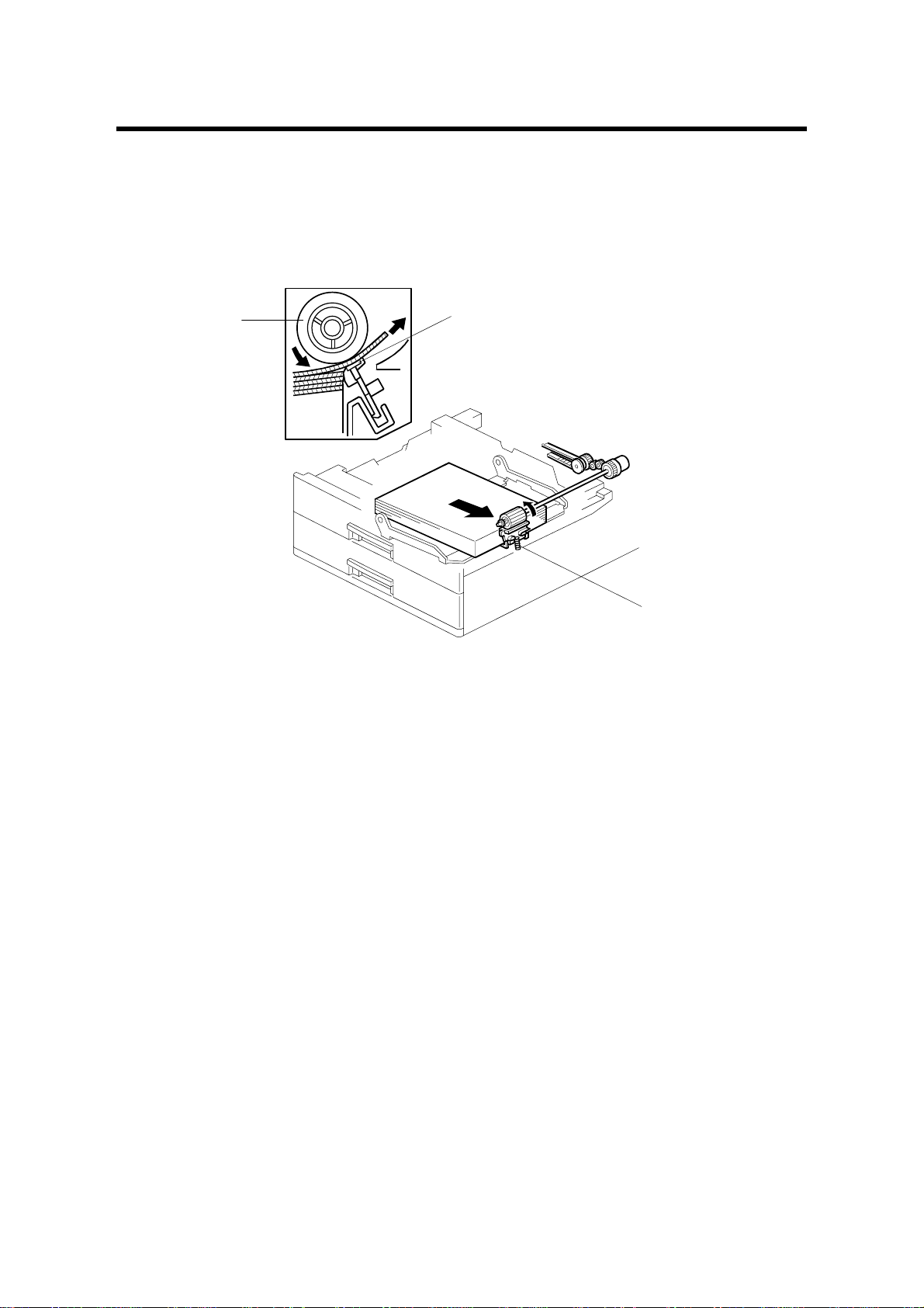
FEED ROLLER REPLACEMENT 10 August, 2001
3. REPL ACEMENT AND ADJUSTMENT
3.1 FEED ROLLER REPLACEMENT
[C]
[B]
B390R723.WMF
1. Remove the paper tray [A].
2. Move the release lever [B] to the front.
3. Pull the feed roller [C] to the operation side and remove it.
4. Replace the feed roller.
[A]
B390-14
Page 16

10 August, 2001 TRAY MAIN BOARD REPLACEMENT
[A]
B390R101.WMF
[C]
3.2 TRAY MAIN BOARD REPLACEMENT
1. Remove the rear cover [A] (4 screws).
2. Replace the tray main board [B] (4 screws and 8 connectors).
3.3 TRAY MOTOR REPLACEMENT
1. Remove the rear cover (4 screws).
[B]
B390R103.WMF
2. Disconnect 8 connectors from the tray main board [B].
3. Remove the tray main board with the bracket (2 screws).
4. Remove the tray motor [C] (6 screws and 1 connector).
B390-15
Options
Page 17

RELAY CLUTCH REPLACEMENT 10 August, 2001
3.4 RELAY CLUTCH REPLACEMENT
[A]
[B]
B390R101.WMF
1. Remove the rear cover [A] (4 screws).
2. Remove the right cover [B] (2 screws).
3. Remove the snap ring [C].
4. Remove the bushing [D].
5. Remove the stopper bracket [E] (2 screws).
6. Replace the relay clutch [F] (1 connector).
[D]
[C]
[E]
[F]
B390R102.WMF
B390-16
Page 18

10 August, 2001 UPPER PAPER FEED CLUTCH REPLACEMENT
3.5 UPPER PAPER FEED CLUTCH REPLACEMENT
[A]
B390R101.WMF
[B]
1. Remove the rear cover [A] (4 screws).
2. Remove the bracket [B] (2 screws).
3. Remove the snap ring [C].
4. Remove the bushing [D].
5. Remove the stopper bracket [E] (2 screws).
6. Replace the upper paper feed clutch [F] (1 connector).
[F]
[D]
[C]
[E]
B390R102.WMF
B390-17
Options
Page 19

LOWER PAPER FEED CLUTCH REPLACEMENT 10 August, 2001
3.6 LOWER PAPER FEED CLUTCH REPLACEMENT
[A]
B390R101.WMF
1. Remove the rear cover [A] (4 screws).
2. Remove the snap ring [B].
3. Replace the lower paper feed clutch [C].
[C]
[B]
B390R102.WMF
B390-18
Page 20

10 August, 2001 LIFT MOTOR REPLACEMENT
3.7 LIFT MOTOR REPLACEMENT
[A]
B390R101.WMF
[B]
[D]
[F]
B390R104.WMF
1. Pull out the paper tray.
2. Remove the rear cover [A] (4 screws) and the bracket [B] (2 screws).
3. Disconnect the 2P connector [C].
4. Remove the spring [D].
5. Remove the lift motor unit [E] (3 screws).
6. Remove the lift motor [F] (2 screws).
[E]
[C]
B390-19
Options
Page 21

PAPER END SENSOR REPLACEMENT 10 August, 2001
3.8 PAPER END SENSOR REPLACEMENT
[C]
[B]
[A]
B390R106.WMF
1. Remove the paper tray.
2. Remove the paper end sensor bracket [A] (1 screw and 1 connector).
3. Replace the paper end sensor [B].
NOTE: After replacing the sensor, pull the sensor cable towards the right side of
the frame [C] so that it does not touch the paper in the tray.
3.9 VERTICAL TRANSPORT SENSOR REPLACEMENT
[C]
[D]
[B]
[A]
B390R105.WMF
1. Open the right door [A].
2. Remove the right guide plate [B] (2 screws).
3. Remove the vertical transport sensor bracket [C] (1 screw and 1 connector).
4. Replace the vertical transport sensor [D].
B390-20
Page 22

10 August, 2001 PAPER SIZE SWITCH REPLACEMENT
3.10 PAPER SIZE SWITCH REPLACEMENT
[B]
[A]
B390R108.WMF
1. Remove the upper and lower paper trays.
2. Remove the inner cover [A] (2 screws).
3. Replace the paper size switch [B] (1 connector).
Options
B390-21
 Loading...