

Page 1

LARGE CAPACITY TRAY
(Machine Code: G569)
Page 2
23 February, 2001 DETACHING THE TRAY FROM THE MAINFRAME
1. REPLACEMENT AND ADJUSTMENT
1.1 DETACHING THE TRAY FROM THE MAINFRAME
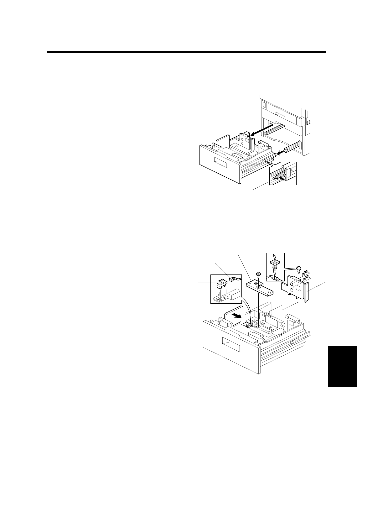
1. To draw the tray out, press the
stopper [A] on the guide rail.
2. To install the tray, set the tray on the
guide rails, keep the tray level, and
push the tray in.
1.2 REAR FENCE HP SENSOR
1. Pull out the large capacity tray.
2. Left tray rear side fence [A] (! x 2)
3. Rear fence bracket [B] (! x 1)
4. Connector of the rear fence HP
sensor [C]
5. Rear fence HP sensor [D] (! x 1)
[D]
[C]
[B]
[A]
G569R101.WMF
[A]
G569-1
G569R102.WMF
Peripherals
Page 3
CHANGING THE TRAY PAPER SIZE 23 February, 2001
1.3 CHANGING THE TRAY PAPER SIZE
[A]
[B]
A4
A4
Lt
Lt
G569R103.WMF
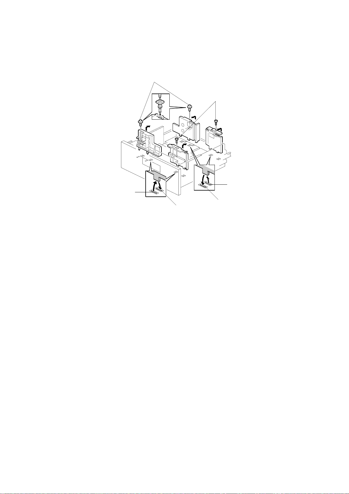
1. Screws [A] [B]
2. Change the position of the side fences.
3. Change the position of the rear fence HP sensor (☛ 1.2 REAR FENCE HP
SENSOR).
4. Before securing the right tray side fence, load the paper in the right tray, and
adjust the fence.
G569-2
Page 4
23 February, 2001 LEFT TRAY PAPER END SENSOR
1.4 LEFT TRAY PAPER END SENSOR
[B]
[A]
[C]
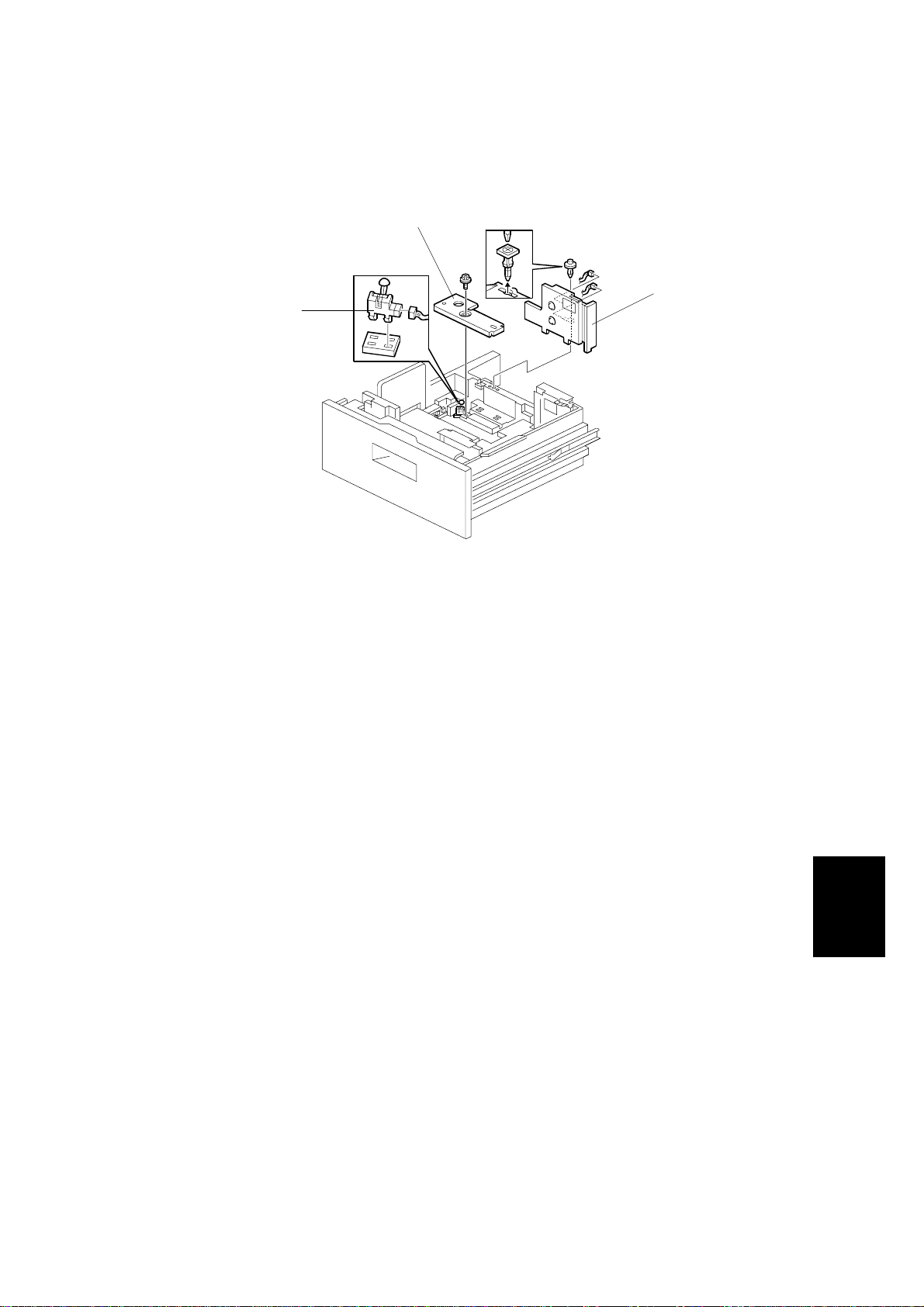
1. Pull out the large capacity tray.
2. Left tray side fence [A] (! x 2)
3. Rear fence bracket [B] (! x1)
4. Left tray paper end sensor [C] (" x 1)
G569R104.WMF
Peripherals
G569-3
Page 5
TRAY LIFT MOTOR 23 February, 2001
1.5 TRAY LIFT MOTOR
[A]
G569R105.WMF
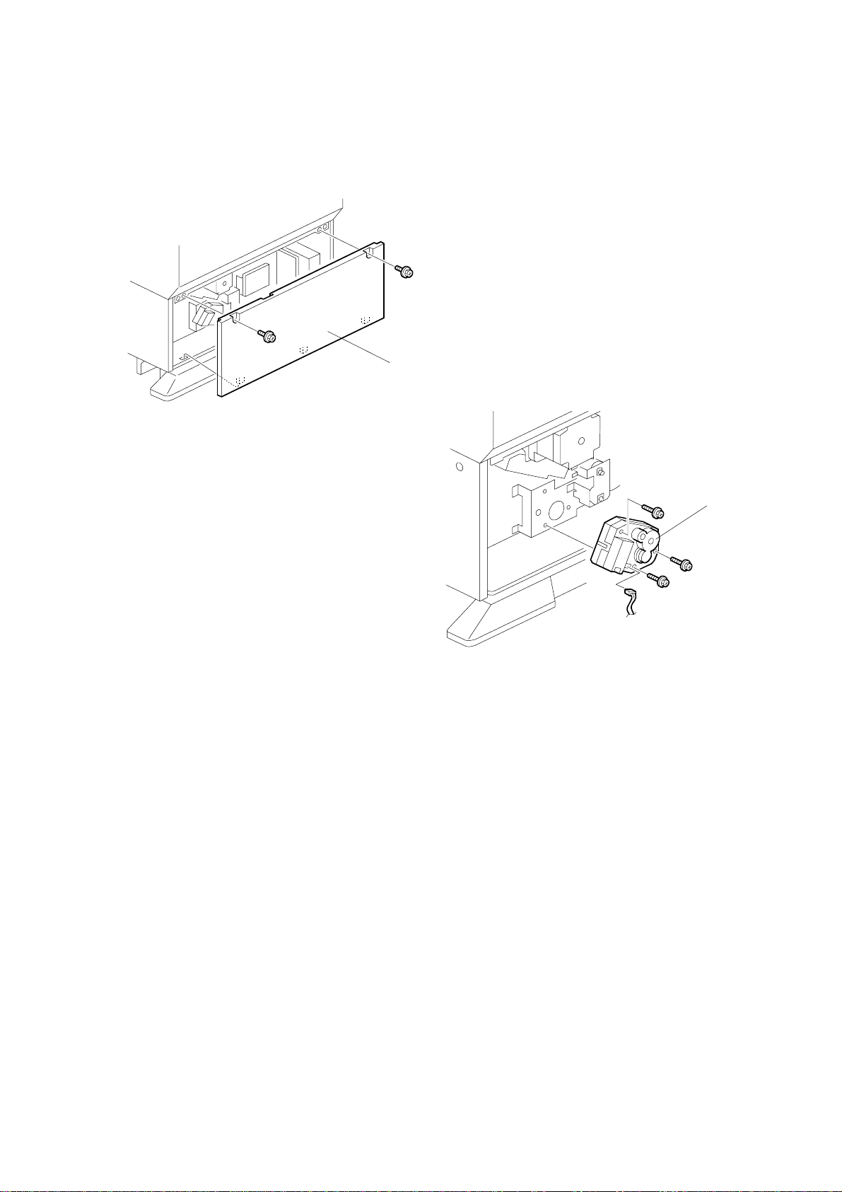
1. Rear cover [A] (! x 2)
2. Tray lift motor [B] (! x 3, " x 1)
[B]
G569R106.WMF
G569-4
Page 6
23 February, 2001 TRAY MOTOR AND STACK TRANSPORT CLUTCH
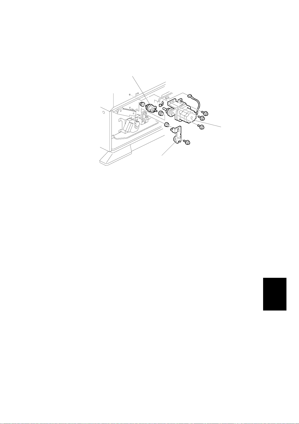
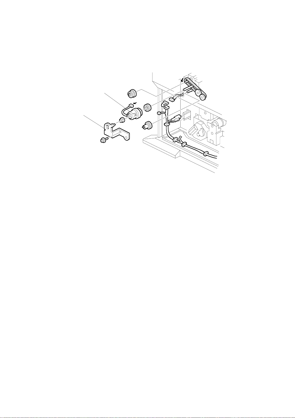
1.6 TRAY MOTOR AND STACK TRANSPORT CLUTCH
[C]
[A]
[B]
G569R107.WMF
1. Rear cover (☛ 1.5 TRAY LIFT MOTOR)
2. Tray motor [A] (! x 6, " x 1)
3. Bracket [B] (! x 1)
4. Stack transport clutch [C] (! x 2, 2 bushings, 1 gear)
Peripherals
G569-5
Page 7
PAPER FEED CLUTCH 23 February, 2001
1.7 PAPER FEED CLUTCH
[B]
[A]
1. Rear cover (☛ 1.5 TRAY LIFT MOTOR)
2. Bracket [A] (! x 1)
3. Bushing
4. Paper feed clutch [B]
G569R108.WMF
G569-6
Page 8

23 February, 2001 PAPER FEED UNIT
1.8 PAPER FEED UNIT
[A]
[C]
[B]
G569R109.WMF
1. Stack transport clutch (☛ 1.6 TRAY MOTOR AND STACK TRANSPORT
CLUTCH)
2. Paper feed clutch (☛ 1.7 REPLACEMENT AND ADJUSTMENT)
3. Paper feed unit cable [A]
4. Open the vertical transport guide plate [B].
5. Paper feed unit [C] (! x 2)
Peripherals
G569-7
Page 9

UPPER LIMIT, RIGHT TRAY PAPER END, AND RELAY SENSORS 23 February, 2001
1.9 UPPER LIMIT, RIGHT TRAY PAPER END, AND
RELAY SENSORS
[A]
[D]
[C]
1. Paper feed unit (☛ 1.8 PAPER FEED UNIT)
2. Sensors
• Upper limit [A]
• Relay [B] (! x 1, 1 bracket)
• Right tray paper end [C]
[B]
G569R111.WMF
NOTE: To remove the upper limit [A] or paper end sensor[C], press the lever [D]
and hold it down.
G569-8
Page 10

23 February, 2001 PICK-UP/PAPER FEED/SEPARATION ROLLER
1.10 PICK-UP/PAPER FEED/SEPARATION ROLLER
[C]
[A]
[B]
G569R110.WMF
1. Paper tray unit
2. Pick-up roller [A] (1 hook)
3. Separation roller [B] (# x 1)
4. Feed roller [C] (# x 1)
NOTE: If the rollers are incorrectly installed, the one-way clutch does not work.
Peripherals
G569-9
Page 11

OVERVIEW 23 February, 2001
2. DETAILED SECTION DESCRIPTIONS
2.1 OVERVIEW
2.1.1 MECHANICAL COMPONENT LAYOUT
1 2 4 5 6 7 8
3
G569D001.WMF
1213
9
10
11
1. Paper Height Sensors 5
2. Paper Height Sensors 4
3. Paper Height Sensors 1
4. Pick-up Roller
5. Upper Limit Sensor
6. Paper Feed Roller
7. Relay Sensor
8. Relay Roller
9. Separation Roller
10. Paper Height Sensors 2
11. Paper Height Sensors 3
12. Lower Limit Sensor
13. Left Paper End Sensor
G569-10
Page 12

23 February, 2001 OVERVIEW
2.1.2 ELECTRICAL COMPONENT LAYOUT
3
2
4
1
5
6
7
8
9
10
11
12
13
14
15
16
17
181920
G569D101.WMF
1. End Fence Home Position Sensor
2. Left Tray Paper End Sensor
3. Paper Height Sensor 4
4. Paper Height Sensor 5
5. Paper Size Sensor
6. Main Board
7. Side Fence Open/Closed Sensor
8. Tray Sensor
9. Tray Motor
10. Paper Height Sensors 1
11. Upper Limit Sensor
12. Paper Feed Clutch
13. Paper Height Sensor 2
14. Right Tray Paper End Sensor
15. Paper Height Sensor 3
16. Vertical Guide Switch
17. Lower Limit Sensor
18. Tray Lift Motor
19. Relay Sensor
20. Stack Transport Clutch
Peripherals
G569-11
Page 13

PAPER FEED 23 February, 2001
2.2 PAPER FEED
[A]
[B]
[C]
G569D102.WMF
• This product uses an FRR type paper feed mechanism.
• The paper feed unit consists of the pick-up roller [A], paper feed roller [B],
separation roller [C], and relay roller.
• There is a torque limiter (ferrite powder type) in the back of the separation roller.
G569-12
Page 14

23 February, 2001 SEPARATION ROLLER AND PICK-UP ROLLER RELEASE
2.3 SEPARATION ROLLER AND PICK-UP ROLLER
RELEASE
[A]
[E]
G569D107.WMF
[C]
[B]
[E]
[A]
[D]
G569D108.WMF
To prevent the paper from being torn when pulling out the paper feed tray, the
separation and pickup rollers are set so that they release automatically.
When the paper tray [A] is not inside the machine, the separation roller [B] is away
from the paper feed roller [C] and the pick-up roller [D] stays in the upper position.
When the paper tray is set into the machine, it pushes the release lever [E]. This
causes the pick-up roller to go down into contact with the top sheet of paper and
the separation roller to move up and contact the paper feed roller.
Peripherals
G569-13
Page 15

TRAY LIFT 23 February, 2001
2.4 TRAY LIFT
[G]
[F]
[E]
[A]
[C]
[D]
[B]
G569D103.WMF
When the paper feed tray is put in the m achine, the tray sensor on the back face
turns on and the tray lift motor [A] starts. The base plate lift shaft [B] is coupled to
the lift motor at shaft [C], so the base plate of the tray is lifted. After a short while,
the top of the paper stack contacts the pick-up roller and lifts it up.
When this occurs, the actuator enters the upper limit sensor, the sensor turns off
and the lift motor stops. When paper in the tray is used up, the pick-up roller is
gradually lowered, and the actuator leaves the upper limit sensor (turning the
sensor on). When this happens, the lift motor begins turning again. The tray will
then be lifted until the actuator enters the upper limit sensor (turning the sensor off
again).
When the tray is removed from the printer, the coupling between the lift motor and
base plate lift shaft is broken and the base plate goes into a controlled free fall
(using a damper [D] to slow the fall and prevent damage).
G569-14
Page 16

23 February, 2001 NEAR END/END DETECTION
2.5 NEAR END/END DETECTION
This tray holds two stacks of paper, so the machine needs to monitor the status of
both these stacks. There are seven sensors to do this.
In the right tray (paper feed side), three height sensors ([E] in the diagram on the
previous page) measure the height of the stack, and an end sensor detects when
all the paper is used up. As the amount of paper remaining in the tray decreases,
the base plate rises and the actuator activates the paper height sensors. When
paper runs out in the right tray, the stack in the left tray is moved across to the right
tray.
There are also two height sensors ([F] in the diagram on the previous page) and an
end sensor in the left tray (paper storage side) ([G] in the diagram on the previous
page). When there is no paper in both trays, paper end is detected.
The machine determines the amount of remaining paper based on the sensor
outputs, as shown in the following table.
Amount of paper
100% 75% 50%
Paper Height Sensor 1
Paper Height Sensor 2
Paper Height Sensor 3
Right Tray Paper End Sensor
Paper Height Sensor 4
Paper Height Sensor 5
Left Tray Paper End Sensor
❍❍❍❍❍❍#❍❍
❍❍❍❍❍#
❍❍#❍ ❍
#########
❍❍❍##❍❍❍❍
❍#❍##❍❍##
❍❍❍❍#❍❍❍❍
––
–
❍#
#
–
Amount of paper
25% Near-end End
Paper Height Sensor 1
Paper Height Sensor 2 –
Paper Height Sensor 3 –
Right Tray Paper End Sensor
Paper Height Sensor 4
Paper Height Sensor 5
Left Tray Paper End Sensor
Right tray paper end sensor: ❍ = Low (no paper), # = High (paper present)
Other sensors: ❍ = Low (paper present), # = High (no paper)
#❍❍❍❍##
❍#❍#
#
#######❍
❍#######
########
❍❍❍##❍##
–
#
––––
–––
The following diagram is the sensor layout, as viewed from the front.
Paper Storage Side Paper Feed Side
Paper End
Sensor 1
Paper Height
Sensor 1
Paper Height
Sensor 5
Paper Height
Sensor 4
Paper Height
Sensor 2
Paper Height
Sensor 3
–
Peripherals
Paper End
Sensor 2
G569D112.WMF
G569-15
Page 17

PAPER STACK TRANSPORT MECHANISM 23 February, 2001
2.6 PAPER STACK TRANSPORT MECHANISM
[C]
[E]
[D]
[B]
[A]
G569D104.WMF
When the pa per in the right tray is used up, t he tray motor [A] and stack t ransport
clutch [B] turn on. Then the rear fence [C] moves the stack of paper from the left
tray to the right tray.
While the stack is being moved, it pushes the side fence aside, and the side fence
open/closed sensor [D] detects that the fence is open.
After the stack has been moved across, a spring in the side fence moves the side
fence back, and the sensor detects that the fence is closed. Then, the tray motor
reverses until end fence home position sensor [E] is deactivated.
G569-16
Page 18

23 February, 2001 RIGHT TRAY PAPER END DETECTION
2.7 RIGHT TRAY PAPER END DETECTION
[A]
[B]
[C]
G569D106.WMF
[E]
G569D111.WMF
[D]
The paper end sensor [A] detects when copy paper in the right tray runs out.
When there is paper in the tray, the paper pushes up the paper end feeler [B] and
causes the actuator to enter the sensor. When paper runs out, the feeler drops and
the actuator leaves the sensor, and the machine detects that there is no paper in
the tray.
When the tray is being pulled out, the lever [E] lifts the pick-up roller and this also
lifts up the feeler.
Peripherals
G569-17
Page 19

ABCDEFGH
POINT TO POINT WIRING DIAGRAM (Large Capacity Tray: G569)
!
"
[ ]
C
N
1
2
0
C
N
1
2
1
126
- 8
- 7
- 6
- 5
- 4
- 3
- 2
- 1
- 7
- 6
- 5
- 4
- 3
- 2
- 1
C
N
2
- 2
1
2
- 1
4
- 2
1
6
- 1
5
- 2
- 1
- 1
C
- 3
N
1
2
- 2
8
DC Line
Pulse Signal
Signal Direction
Active High
Active Low
Signal Level
H1
Tray
Heater
(Option)
CN100
- 1
- 2
- 3
- 4
- 5
- 6
- 7
- 8
- 9
- 10
- 11
- 12
- 13
- 14
CN101
- 1
- 2
- 4
- 5
- 6
- 7
CN102
- 1
- 2
- 7
- 8
- 9
- 10
CN103
- 1
- 2
- 4
TXD
RXD
[0] CGND
[0] CGND
[5] Vcc
[5] Vcc
[0] AGND
[0] AGND
[0] AGND
[0] AGND
[24] Vaa
[24] Vaa
[24] Vaa
[24] Vaa
[24] Vaa.SW
[24] Vaa.SW
[24 0/24]
[24 0/24]
[24 0/24]
[24 0/24]
[24] Vaa
[ 24]"
[24] Vaa
[ 24]"
(+)
(-)
[ 24]!
[ 24]!
[24] Vaa
Open
[ 24]!
[ 24]!
Vaa.SW
Main Board
A
AB
B
BB
(PCB1)
1
2
3
4
5
6
Main Frame
Tray Motor
Paper Feed Clutch
Transport Clutch
Tray Lift Motor
Vertical Guide Switch
PSU
SW1
Symbol Table
C
N
1
M1
MC1
MC2
M2
CGND [0]
Vcc [5]
CGND [0]
Vcc [5]
CGND [0]
Vcc [5]
CGND [0]
CGND [0]
Vcc [5]
CGND [0]
Vcc [5]
CGND [0]
Vcc [5]
CGND [0]
Vcc [5]
CGND [0]
A4
Vcc [5]
CGND [0]
Close
Vcc [5]
CGND [0]
Vcc [5]
CGND [0]
Vcc [5]
CGND [0]
Vcc [5]
CGND [0]
Vcc [5]
[ 5]!
[ 5]!
[ 5]
"
[ 5]
"
[ 5]
"
[ 5]!
[ 5]!
[ 5]!
[ 5]!
[ 5]!
[ 5]!
[ 5]!
[ 5]
"
[ 5]
"
CN104
- 1
- 2
- 3
- 4
- 5
- 6
- 7
- 8
- 9
CN106
- 1
- 2
- 7
- 8
- 9
- 10
- 11
- 12
- 13
- 14
- 15
CN108
- 1
- 2
- 3
- 4
- 5
- 6
- 7
- 8
- 9
CN109
- 1
- 2
- 3
- 4
- 5
- 6
- 7
- 8
- 9
- 10
- 11
- 12
- 1
- 9
- 2
- 8
- 3
- 7
CN129
CN235
- 4
- 6
- 5
- 5
- 6
- 4
- 7
- 3
- 8
- 2
- 9
- 1
- 6
- 5
- 4
- 3
- 2
- 1
- 7
- 6
- 5
- 4
- 3
- 2
- 6
- 5
- 4
- 3
- 2
CN170
CN172
- 1
- 7
- 6
- 5
- 4
- 3
- 2
- 3
819 820 821
- 2
- 1
- 3
- 2
- 1
- 3
- 2
- 1
- 2
- 1
- 3
- 2
- 1
- 3
- 2
- 1
- 3
- 2
- 1
- 3
- 2
- 1
- 3
- 2
- 1
- 3
- 2
- 1
- 3
- 2
- 1
- 3
- 2
- 1
- 3
- 2
- 1
- 3
- 2
- 1
131
134 135 176 177
136
160 161
162
174 175
S3
S2
S1
S12
S5
S6
S7
S4
S10
S13
S14
S11
S8
S9
Upper Limit Sensor
Relay Sensor
Right Tray
Paper End Sensor
Tray Sensor
Paper Height Sensor - 1
Paper Height Sensor - 2
Paper Height Sensor - 3
Lower Limit Sensor
Paper Size Sensor
Side Fence Open/Close
Sensor
Left Tray Paper End Sensor
End Fence HP Sensor
Paper Height Sensor 4
Paper Height Sensor 5
1
2
3
4
5
6
ABCDEFGH
Page 20

ELECTRICAL COMPONENT LAYOUT (G569)
3
2
1
5
6
7
8
9
10
11
12
13
14
15
16
17
181920
G569D101.WMF
Page 21

ELECTRICAL COMPONENT DESCRIPTION (G569)
Symbol Description Index No. P-to-P
M1 Tray Motor 9 B3
M2 Tray Lift Motor 18 B4
S1 Right Tray Paper End 14 G2
S2 Relay 19 G1
S3 Upper Limit 11 G1
S4 Lower Limit 17 G3
S5 Paper Height 1 10 G2
S6 Paper Height 2 13 G3
S7 Paper Height 3 15 G3
S8 Paper Height 4 3 G5
S9 Paper Height 5 4 G6
S10 Paper Size 5 G4
S11 End Fence Home Position 1 G5
S12 Tray 8 G2
S13 Side Fence Open/Closed 7 G4
S14 Left Tray Paper End 2 G5
SW1 Vertical Guide 16 B5
MC1 Paper Feed 12 B3
MC2 Stack Transport 20 B4
PCB1 Main 6 D6
H1 Tray Heater (Option) - C2
 Loading...