

Page 1

PAPER TRAY UNIT
(Machine Code: G520)
Page 2

30 July 1999 SPECIFICATIONS
1. OVERALL MACHINE INFORMATION
1.1 SPECIFICATIONS
Paper Size
Paper Weight: 60 g/m2 ~ 105 g/m2, 16 lb. ~ 28 lb.
Tray Capacity: 500 sheets (80 g/m2, 20 lb.)
Paper Feed System: FRR
Paper Height Detection: 4 steps (100%, 70%, 30%, Near end)
Power Source: 24 Vdc, 5 Vdc (from the copier)
Power Consumption: 50 W
Weight: 25 kg
Size (W x D x H): 540 mm x 600 mm x 270 mm
:
A5 lengthwise to A3
HLT lengthwise to DLT
120 Vac: 115 V version (from the copier)
220 ~ 240 Vac: 224/240 V version (from the copier)
G520-1
Options
Page 3
MECHANICAL COMPONENT LAYOUT 30 July 1999
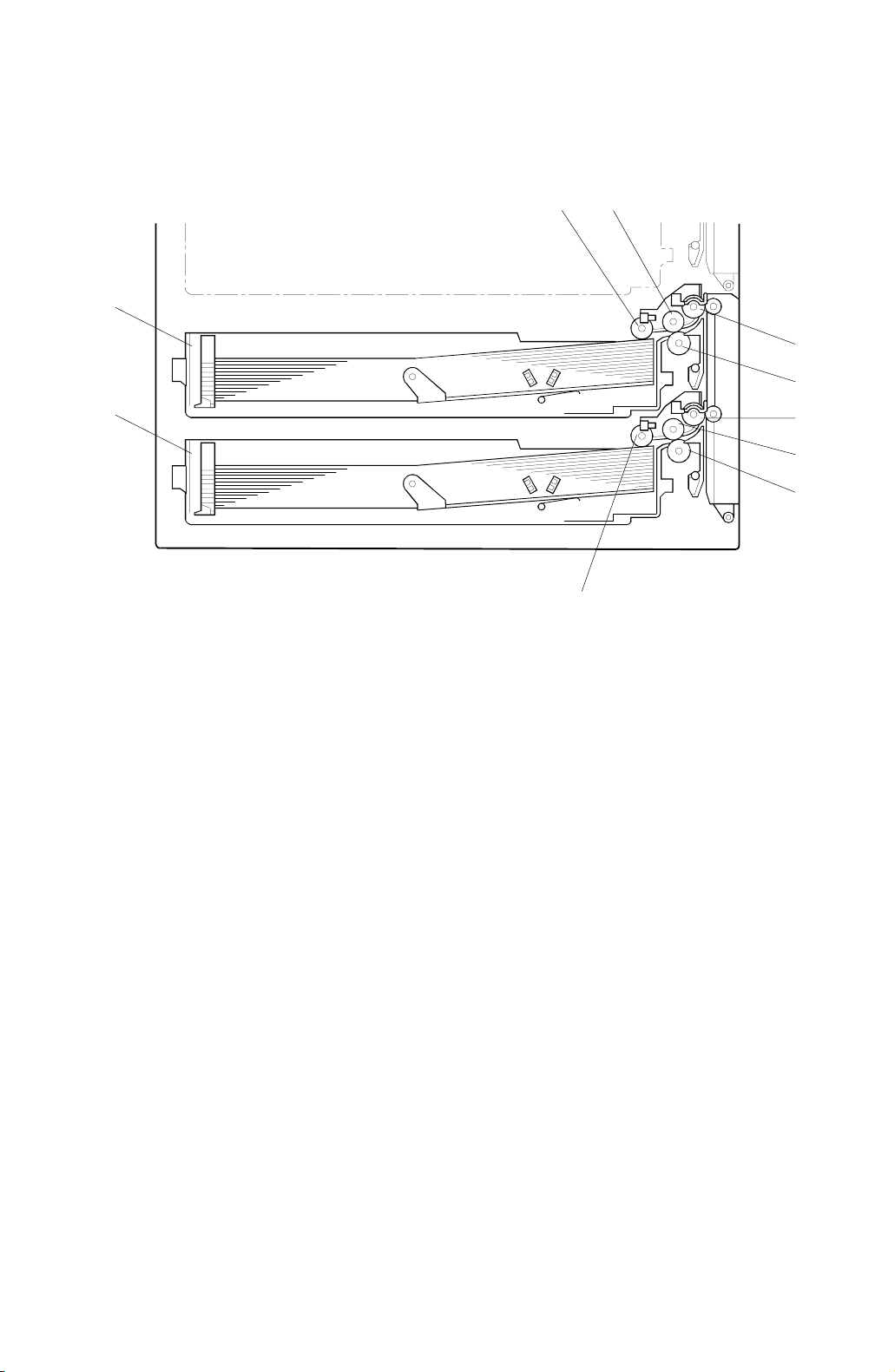
1.2 MECHANICAL COMPONENT LAYOUT
21
10
3
4
9
1. Upper pick-up roller
2. Upper paper feed roller
3. Upper relay roller
4. Upper separation roller
5. Lower relay roller
8
G520V500.WMF
6. Lower paper feed roller
7. Lower separation roller
8. Lower pick-up roller
9. Lower tray
10. Upper tray
5
6
7
G520-2
Page 4
30 July 1999 ELECTRICAL COMPONENT LAYOUT
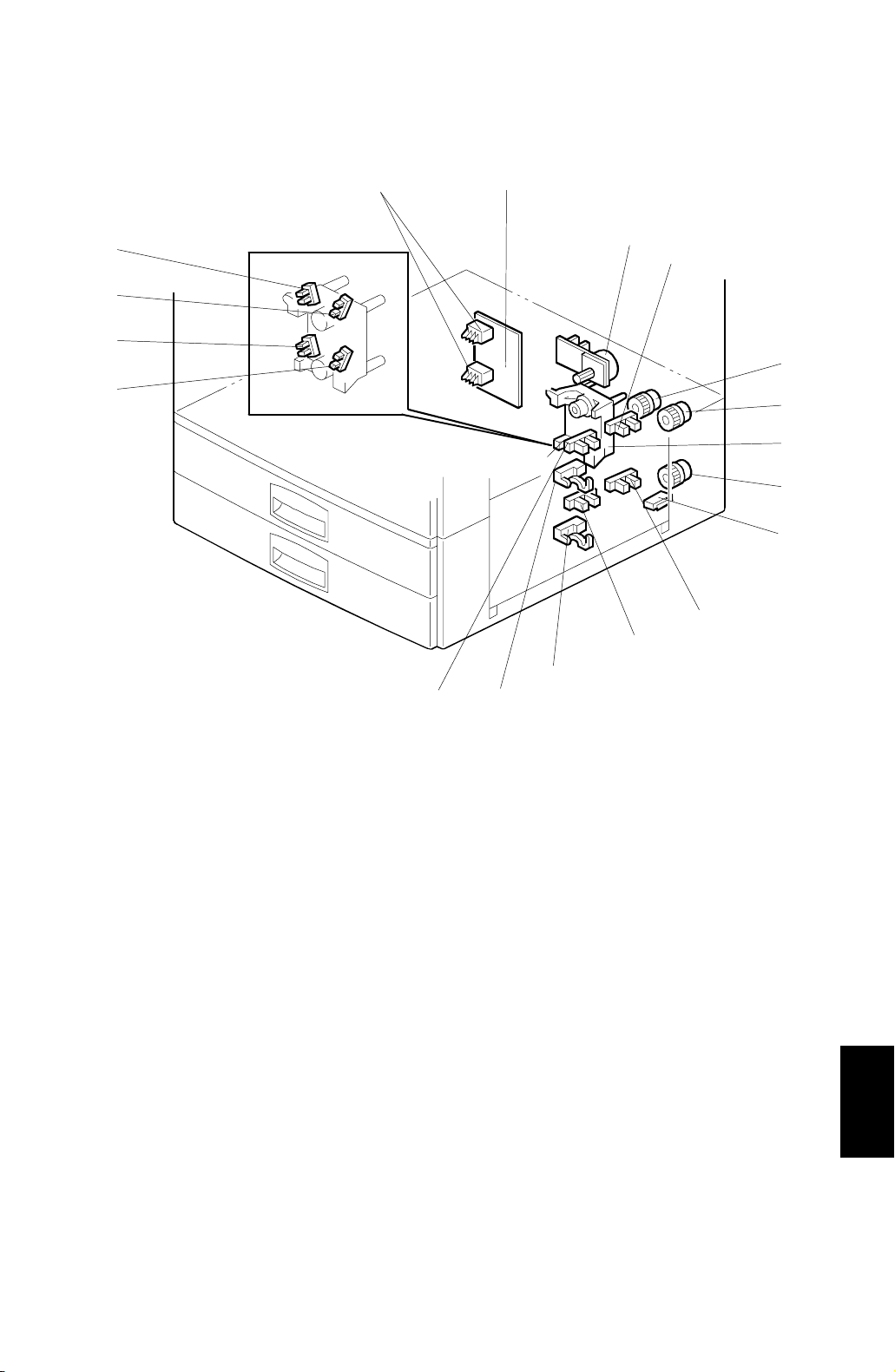
1.3 ELECTRICAL COMPONENT LAYOUT
17
16
15
14
18
13
1
2
3
4
5
6
7
8
9
10
11
12
1. Main board
2. Tray motor
3. Upper paper lift sensor
4. Relay clutch
5. Upper paper feed clutch
6. Tray lift motor
7. Lower paper feed clutch
8. Vertical guide switch
9. Lower paper lift sensor
G520V501.WMF
10. Lower paper end sensor
11. Lower relay sensor
12. Upper relay sensor
13. Upper paper end sensor
14. Lower paper height 2 sensor
15. Lower paper height 1 sensor
16. Upper paper height 2 sensor
17. Upper paper height 1 sensor
18. Tray paper size switch
Options
G520-3
Page 5

ELECTRICAL COMPONENT DESCRIPTION 30 July 1999
1.4 ELECTRICAL COMPONENT DESCRIPTION
Symbol Name Function Index No.
Motors
M1 Tray Drives all rollers . 2
Tray Lift
M2
Sensors
S1
S2
S3
S4
S5 Upper Relay Detects misfeeds. 12
S6 Lower Relay Detects misfeeds. 11
S7
S8
S9
S10
Upper Paper Lift Detects when the paper in the upper tray is
Lower Paper Lift Detects when the paper in the lower tray is
Upper Paper End Inf orms the copier when the upper tray runs
Lower Paper End
Upper Paper Height 1 Detects the amount of paper in the upper
Upper Paper Height 2
Lower Paper Height 1 Detect s the amount of paper in the lower
Lower Paper Height 2 Detect s the amount of paper in the lower
Lifts the upper and lower tray bottom plates
(there are two motors in this unit, one for
each tray.
at the correct feed height.
at the correct feed height.
out of paper.
Informs the copier when the upper tray runs
out of paper.
tray.
Detects the amount of paper in the upper
tray.
tray.
tray.
6
3
9
13
10
17
16
15
14
Switches
SW1 Vertical Guide Detects whether the vertical guide is open. 8
SW2
Magnetic Clutches
MC1 Upper Paper Feed Starts paper feed from the upper tray. 5
MC2 Lower Paper Feed Starts paper feed from the lower tray. 7
MC3 Relay Drives the transport rollers. 4
PCBs
PCB1
Tray Paper Size Detects the paper size in the paper tray
based on a dial setting.
Main Controls the paper tray unit and
communicates with the copier.
18
1
G520-4
Page 6
30 July 1999 DRIVE LAYOUT
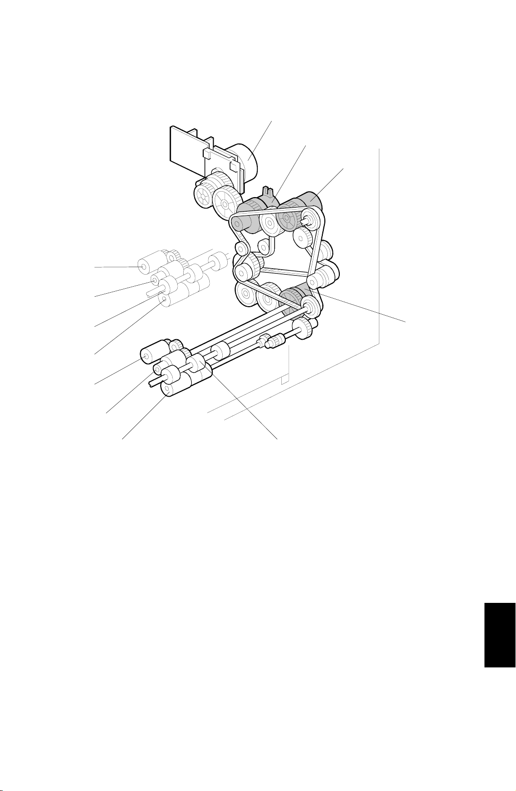
1.5 DRIVE LAYOUT
1
2
3
12
11
10
9
8
7
1. Tray motor
2. Relay clutch
3. Upper paper feed clutch
4. Lower paper feed clutch
5. Lower relay roller
6. Lower separation roller
4
56
G520V502.WMF
7. Lower paper feed roller
8. Lower pick-up roller
9. Upper separation roller
10. Upper relay roller
11. Upper paper feed roller
12. Upper pick-up roller
G520-5
Options
Page 7
PICK-UP AND SEPARATION ROLLER RELEASE MECHANISM 30 July 1999
2. DETAILED DESCRIPTIONS
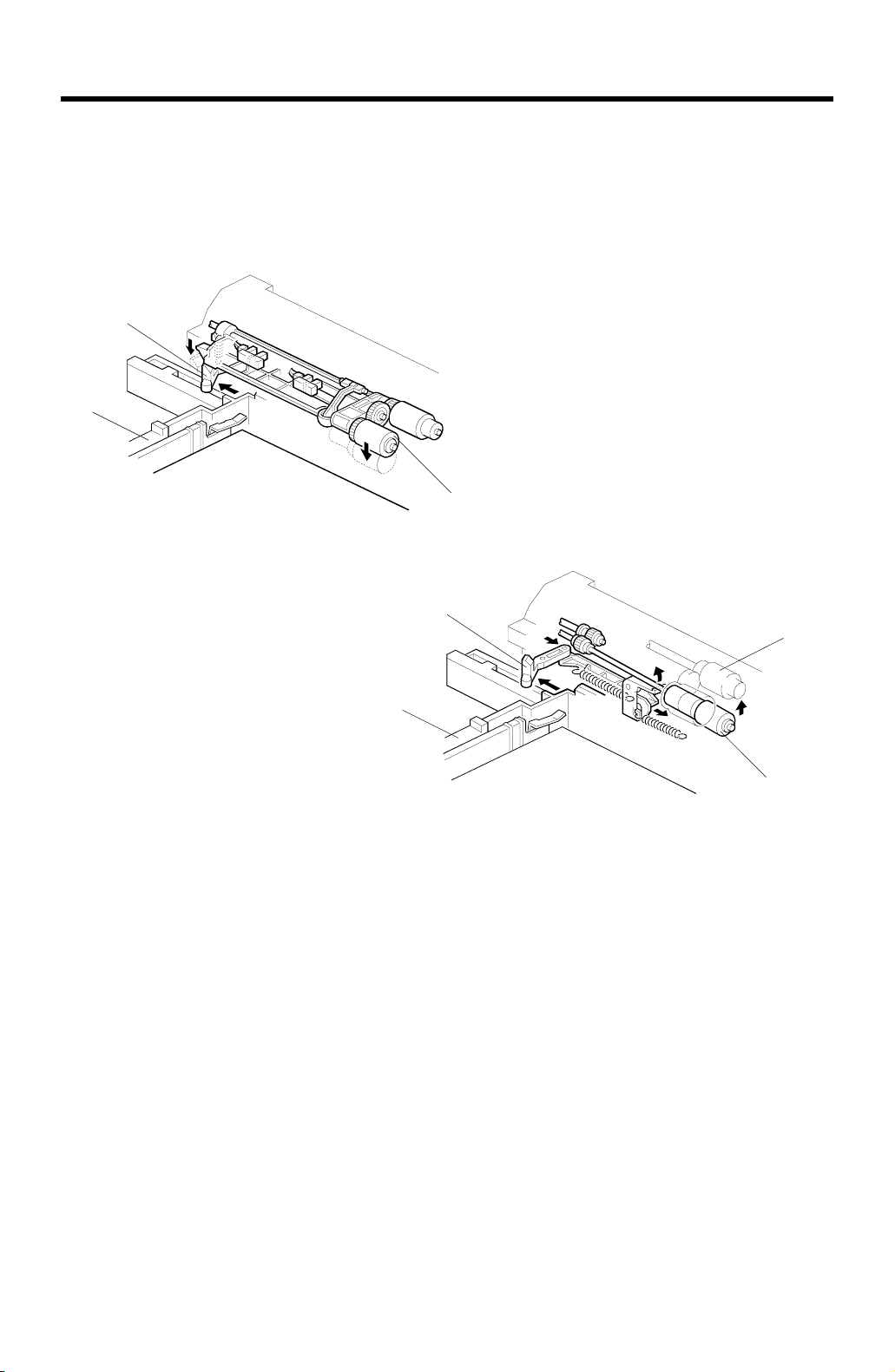
2.1 PICK-UP AND SEPARATION ROLLER RELEASE
MECHANISM
[E]
[A]
[D]
G520500.WMF
[E]
[C]
[A]
[B]
G520D501.WMF
When the paper tray [A] is not inside the paper tr ay unit, the separation roller [B] is
shifted away from the paper feed roller [C], and the pick-up roller [D] stays in the
upper position.
When the pa per tray is put into the paper tray unit, it pushes the release lever [E].
This causes the pick-up roller to move down (top diagram) and the separation roller
to move into contact with the paper feed roller (bottom diagram).
G520-6
Page 8

30 July 1999 PAPER LIFT MECHANISM
2.2 PAPER LIFT MECHANISM
[B]
[H]
[F]
[G]
[E]
[D]
[A]
[C]
G520D502.WMF
The paper size switch [A] detects when the paper tray [B] is placed in the machine.
When the machine detects that the paper tray is in the m achine, the tray lift motor
[C] rotates and the coupling gear [D] on the tray lift motor engages the pin [E] on
the lift arm shaft [F]. Then the tray lift arm [G] lifts the tray bottom plate [H].
Options
G520-7
Page 9

PAPER LIFT MECHANISM 30 July 1999
[C]
[B]
[A]
G520D504.WMF
When the paper tray is placed in the machine, the pick-up roller [A] lowers. When
the top sheet of paper reaches the proper height for paper feed, the paper pushes
up the pick-up roller, and the actuator [B] on the pick-up roller supporter activates
the paper lift sensor [C] to stop the tray lift motor.
After several paper feed cycles, the paper level gradually lowers and the paper lift
sensor is deactivated. The tray lift motor turns on again until this sensor is activated
again.
When the tr ay is drawn out of the machine, the tray lift motor coupling gear
disengages the pin on the lift arm shaft, and the tray bottom plate then drops under
its own weight.
G520-8
Page 10

30 July 1999 PAPER END DETECTION
2.3 PAPER END DETECTION
[B]
[A]
[D]
[C]
G520D503.WMF
If there is some paper in the paper tray, the paper stack raises the paper end feeler
[A] and the paper end sensor [B] is deactivated.
When the paper tray runs out of paper, the paper end feeler drops into the cutout
[C] in the tray bottom plate and the paper end sensor is activated.
When the paper tray is drawn out, the pick-up roller supporter [D] lifts up the paper
end feeler.
G520-9
Options
Page 11

PAPER HEIGHT DETECTION 30 July 1999
2.4 PAPER HEIGHT DETECTION
The amount of paper in the tray is
detected by the combination of two
paper height sensors [A] and [B].
When the am ount of paper decreases ,
the bottom plate pressure lever [C]
moves up and the actuator [D], which
is mounted on the same drive shaft as
the pressure lever, rotates.
The following combination of sensor
signals is sent to the copier.
Amount of
Paper
Full OFF ON
Near Full ON ON
Near End 1 ON OFF
Near End 2 OFF OFF
Paper Height
Sensor [A]
Paper Height
Sensor [B]
[D]
[A]
[B]
Full
3511333435
[C]
3511333435
Near Full
Near End 1
3511333435
Near End 2
3511333436
G520D505.WMF
G520-10
Page 12

30 July 1999 PAPER SIZE DETECTION
2.5 PAPER SIZE DETECTION
The paper size switch includes four sensors (microswitches). Actuators behind the
paper size dial actuate the sensors.
Each paper size has its own actuator, with a unique combination of notches. To
determine the paper size, the CPU reads which switches the actuator has turned
off.
The CPU disables paper feed from a tray if the paper size cannot be detected. If
the paper size actuator is broken, or if there is no tray installed, the printer control
board recognizes that the paper tray is not installed.
When the paper size actuator is at the “[” mark, the paper tray can be set up to
accommodate one of a wider range of paper sizes by using one of the user tools
on the machine’s operation pan el .
Models Switch Location
North America Europe 1 2 3 4
8
" x 13" Portrait A3 Portrait ON ON OFF ON
1/2
A4 Landscape A4 Landscape ON ON ON ON
A4 Portrait A4 Portrait ON OFF ON ON
11" x 17" Portrait A5 Portrait OFF OFF ON ON
8
" x 14" Portrait 8" x 13" Portrait ON OFF OFF OFF
1/2
8
" x 11" Portrait 8
1/2
8
" x 11" Landscape 8
1/2
[[
" x 11" Portrait ON ON OFF OFF
1/2
" x 11" Landscape O N OFF ON OFF
1/2
ON ON ON OFF
ON: Pushed OFF: Not Pushed
Options
G520-11
Page 13

DIP SWITCHES 30 July 1999
3. SERVICE TABLES
3.1 DIP SWITCHES
DPS101
12345678
00000000Default
00000001Free run, feed from upper tray
00000011Free run, feed from lower tray
00000101Free run, feed from upper and lower trays alternately
NOTE:
1) Do not use any other settings.
2) To do the free run, proceed as follows:
a) Remove the paper from the tray (this is because the machine has no
jam detection).
b) Set DPS101 for the required free run as shown above.
c) Turn the main power switch off, wait a few seconds, and then switch
it on.
d) Press SW101 to start the free run.
e) To stop the free run, press SW102.
Description
3.2 TEST POINTS
No. Label Monitored Signal
TP100 (24 V) +24 V
TP101 (GND) Ground
TP103 (TXD) TXD to the copier
TP104 (RXD) RXD from the copier
TP105 (5 V) +5 V
TP106 (GND) Ground
3.3 SWITCHES
No. Function
SW101 Starts the free run
SW102 Stops the free run
3.4 FUSES
No. Function
FU101 Protects the 24 V line.
G520-12
Page 14

30 July 1999 COVER REPLACEMENT
4. REPLACEMENT AND ADJUSTMENT
4.1 COVER REPLACEMENT
[B]
[A]
Right Cover
1. Remove the right cover [A] (2 screws).
Rear Cover
1. Remove the rear cover [B] (2 screws).
G520R500.WMF
G520-13
Options
Page 15

ROLLER REPLACEMENT 30 July 1999
4.2 ROLLER REPLACEMENT
4.2.1 PAPER FEED, SEPARATION, AND PICK-UP ROLLERS
[B]
[A]
[C]
G520R501.WMF
1. Remove the paper tray.
Pick-up Roller
2. Replace the pick-up roller [A].
Paper Feed Roller
2. Replace the paper feed roller [B] (1 snap ring).
Separation Roller
2. Replace the separation roller [C].
G520-14
Page 16

30 July 1999 TRAY MOTOR REPLACEMENT
4.3 TRAY MOTOR REPLACEMENT
[A]
1. Remove the rear cover.
2. Remove the tray motor [A] (1 connector, 3 screws).
G520R502.WMF
G520-15
Options
Page 17

PAPER FEED AND RELAY CLUTCH REPLACEMENT 30 July 1999
4.4 PAPER FEED AND RELAY CLUTCH REPLACEMENT
[F]
[F]
[B]
[D]
[C]
[A]
G520R503.WMF
1. Remove the rear cover.
2. Remove the upper paper feed clutch holder [A] (2 screws).
3. Remove the lower paper feed clutch holder [B] (2 screws).
4. Remove the gear holder [C] (3 screws, 1 spring, 1 bearing).
5. Replace the relay clutch [D] (1 connector).
6. Replace the upper feed clutch [E] (1 bushing, 1 connector).
7. Replace the lower feed clutch [F] (1 connector).
G520-16
Page 18

30 July 1999 PAPER FEED UNIT REPLACEMENT
4.5 PAPER FEED UNIT REPLACEMENT
[C]
[A]
G520R504.WMF
[D]
1. Remove the rear cover.
2. Remove the upper and lower paper feed clutch holder.
3. Remove the gear holder.
4. Remove the upper feed clutch [A] or lower feed clutch [B].
[B]
G520R505.WMF
5. Remove the upper or lower gear [C, D].
G520-17
Options
Page 19

PAPER FEED UNIT REPLACEMENT 30 July 1999
[A]
[B]
[C]
G520R506.WMF
[D]
G520R507.WMF
Upper Paper Feed Unit
6. Remove the docking bracket [A] (1 screw).
7. Remove the vertical transport cover [B] of the copier (1 snap ring).
[F]
[E]
8. Remove the upper paper feed unit [C] (2 screws, 1 connector).
Lower Paper Feed Unit
6. Remove the docking bracket [D] (1 screw).
7. Remove the vertical transport guide [E] (2 screws).
8. Remove the lower paper feed unit [F] (2 screws, 1 connector).
G520-18
Page 20

30 July 1999 PAPER END, TRAY LIFT, AND RELAY SENSOR REPLACEMENT
4.6 PAPER END, TRAY LIFT, AND RELAY SENSOR
REPLACEMENT
[C]
[B]
1. Remove the paper feed unit.
[A]
[D]
G520R508.WMF
Paper End Sensor
2. Replace the paper end sensor [A] (1 connector).
Tray Lift Sensor
2. Replace the paper lift sensor [B] (1 connector).
Relay Sensor
2. Remove the sensor bracket [C] (1 screw).
3. Replace the relay sensor [D] (1 connector).
G520-19
Options
Page 21

1
PCB1
1
Main
B6
2
3 4 5 6 7 8 9 10 11
A
POINT TO POINT DIAGRAM (PAPER TRAY UNIT: G520)
-A1
CN101-3
CN101-3
CN101-3
CN101-3
CN101
CN101
CN107
CN107
CN107-B1
CN107-B4
CN107-A7
-A10
-A11
CN107-B7
-B10
-B11
CN103-1
B
Paper End
C
D
E
Sensor
Paper End
Sensor
F
Sensor
G
Upper Paper
Height 1
Sensor
H
Upper Paper
Height 2
Sensor
Lower Paper
I
Height 1
Sensor
Lower Paper
J
Height 2
Sensor
Upper Tray
K
Paper Size
Switch
L
Lower Tray
Paper Size
Switch
M
Upper
Lift
Sensor
Upper
Sensor
Upper
Relay
Sensor
Lower
Lift
Lower
Lower
Relay
S1
S3
S5
S2
S4
S6
S7
S8
S9
S10
SW2
SW3
-2
-1
-2
-1
-2
-1
-2
-1
-3
-2
-1
-3
-2
-1
-3
-2
-1
-3
-2
-1
-3
-2
-1
-3
-2
-1
Vertical
Guide
Switch
N
1 2 3 4 5 6 7 8 9 10 11
SW1
[0] GND2
-A2
[t5] Upper Lift Sensor
-A3
[5] 5V
-A4
[0] GND2
-A5
[t5] Upper Paper End Sensor
-A6
[5] 5V
-A7
[0] GND2
-A8
[s5] Upper Relay Sensor
-A9
[5] 5V
-B1
[0] GND2
-B2
[t5] Lower Lift Sensor
-B3
[5] 5V
-B4
[0] GND2
-B5
[t5] Lower Paper End Sensor
-B6
[5] 5V
-B7
[0] GND2
-B8
[s5] Lower Relay Sensor
-B9
[5] 5V
-A1
[0] GND2
-A2
[s5]
-A3
[5] 5V
-A4
[0] GND2
-A5
[s5]
-A6
[5] 5V
[0] GND2
-B2
[s5]
-B3
[5] 5V
[0] GND2
-B5
-B6
-A8
-A9
-B8
-B9
-2
-4
Lower Paper
[s5]
Height 1 Sensor
[5] 5V
[s5] Size Upper4
[s5] Size Upper3
[0] GND2
[s5] Size Upper2
[s5] Size Upper1
[s5] Size Upper4
[s5] Size Upper3
[0] GND2
[s5] Size Upper2
[s5] Size Upper1
[24] 24V
[t24] Vertical Guide Switch
[s24] 24V
Main Board (PCB1)
Upper Paper
Height 2 Sensor
Upper Paper
Height 1 Sensor
Lower Paper
Height 2 Sensor
GND2 [0]
TXD
GND2 [0]
RXD
GND2 [0]
5V [5]
GND1 [0]
GND1 [0]
GND1 [0]
24V [24]
24V [24]
24V [24]
GND1 [0]
GND1 [0]
GND1 [0]
GND 1[0]
24V [24]
24V [24]
24V [24]
24V [24]
GND2 [0]
5V [5]
FG
CLOCK
CW[t5]/CCW [s5]
ON/OFF [t5]
Lower Tray: -
Lower Tray: +
Upper Tray: -
Upper Tray: +
Lower Paper
Feed Cl.
Upper Paper
Feed Cl.
Relay Clutch [t24]
[t24]
[t24]
[t24]
[t24]
24V [24]
[t24]
24V [24]
[t24]
24V [24]
LD
CN109-A1
-A2
-A3
-A4
-A5
-A6
-B1
-B2
-B3
-B4
-B5
-B6
CN102-1
-10
-11
-12
-13
-14
-15
CN104-1
CN104-5
-6
CN104-7
-8
CN104-9
-10
-15
-2
-3
-4
-5
-6
-7
-8
-9
-2
-3
-4
s
t
[ ]
-14
-13
-12
-11
-10
-9
-8
M1
-7
-6
-5
-4
-3
-2
-1
-4
-3
-2
SYMBOL TABLE
DC Line
Pulse Signal
Signal Direction
Active High
Active Low
Voltage
M2
-1
-2
MC
-1
-2
MC
-1
-2
MC
-1
2
1
3
Printer
Tray
Motor
Tray Lift
Motor
Lower Paper
Feed Clutch
Upper Paper
Feed Clutch
Relay
Clutch
A
B
PAPER TRAY UNIT (G520) ELECTRICAL COMPONENT LAYOUT
18
19
1
2 3
C
17
16
D
15
4
14
5
E
6
7
F
8
9
G
10
11
13
H
Index
Symbol
Motors
I
M1 2 Tray G10
M2 6 Tray Lift J10
Sensors
S1 3 Upper Paper Lift B2
S2 9 Lower Paper Lift E2
J
S3 13 Upper Paper End C2
S4 10 Lower Paper End F2
S5 12 Upper Relay D2
S6 11 Lower Relay F2
K
S7 15 Upper Paper Height 1 G2
S8 14 Upper Paper Height 2 H2
S9 17 Lower Paper Height 1 I2
S10 16 Lower Paper Height 2 J2
Switches
L
SW1 8 Vertical Guide N2
SW2 19 Upper Tray Paper Size K2
SW3 18 Lower Tray Paper Size L2
Magnetic Clutches
M
MC1 5 Upper Paper Feed K10
MC2 7 Lower Paper Feed K10
MC3 4 Relay L10
PCB
N
No. Description P to P
12
 Loading...