

Ricoh ps420 SPECIFICATIONS

LCT
(Machine Code: A862)

20 September 1999 SPECIFICATIONS
1. OVERALL MACHINE INFORMATION
1.1 SPECIFICATIONS
Paper Size
Paper Weight: 60 g/m2 ~ 105 g/m2, 16 lb ~ 28 lb
Tray Capacity: 2,000 sheets (80 g/m2, 20lb)
Remaining Paper Detection: 5 steps (100%, 75%, 50%, 25%, Near end)
Power Source: 24 Vdc, 5 Vdc (from copier)
Power Consumption: 26 W (Max.)/14 W (Ave.)
Weight: 25 kg (55 lbs)
Size (W x D x H): 550 mm x 520 mm x 271 mm
:
A4 sideways/LT sideways
A862-1
Options
MECHANICAL COMPONENT LAYOUT 20 September 1999
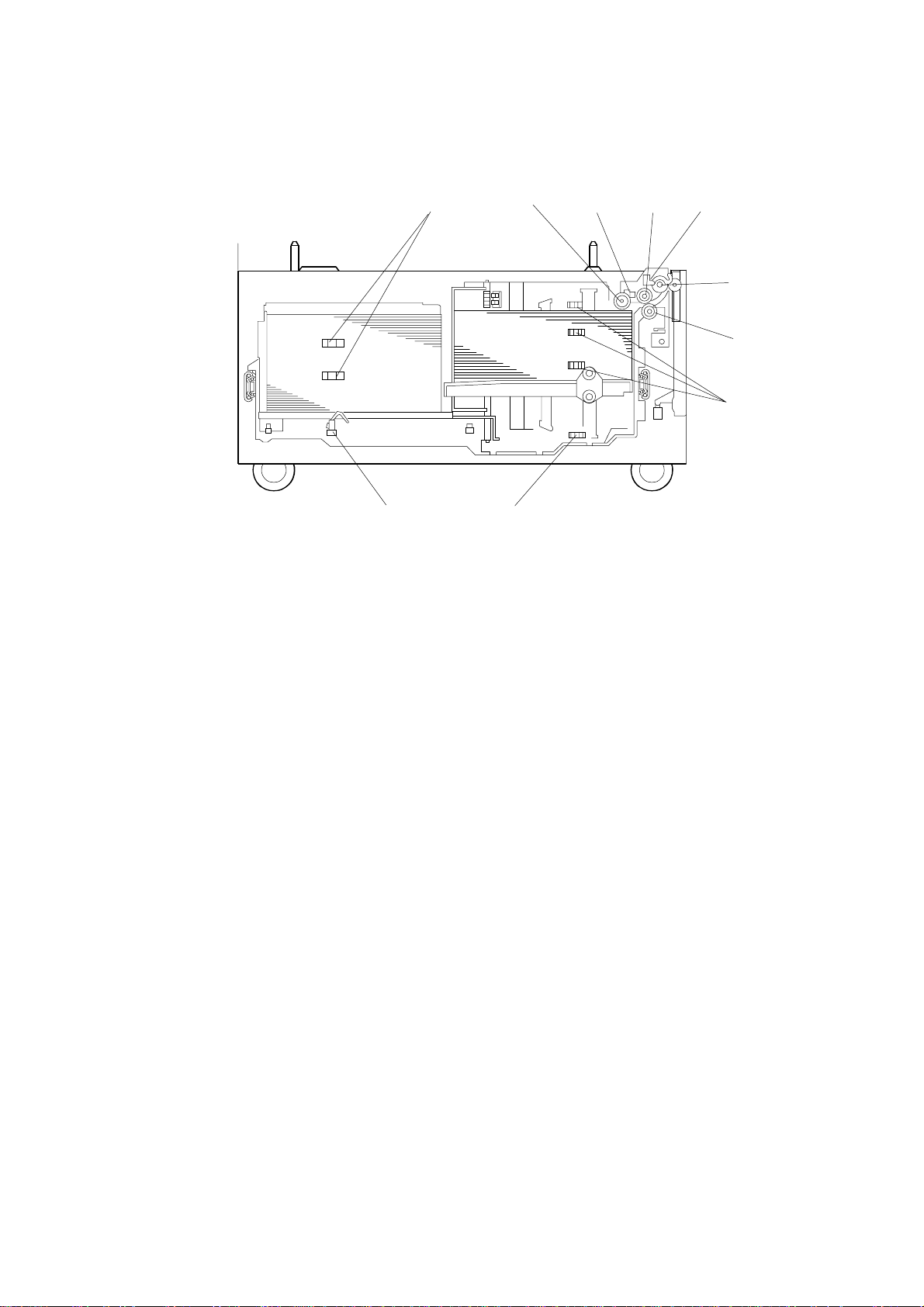
1.2 MECHANICAL COMPONENT LAYOUT
1. Pick-up Roller
10
2143
5
6
7
89
A862D101.WMF
7. Paper Height Sensors 1, 2, 3
2. Upper Limit Sensor
3. Paper Feed Roller
4. Relay Sensor
5. Relay Roller
6. Reverse Roller
8. Lower Limit Sensor
9. Left Paper End Sensor
10. Paper Height Sensors 4,5
A862-2
20 September 1999 ELECTRICAL COMPONENT LAYOUT
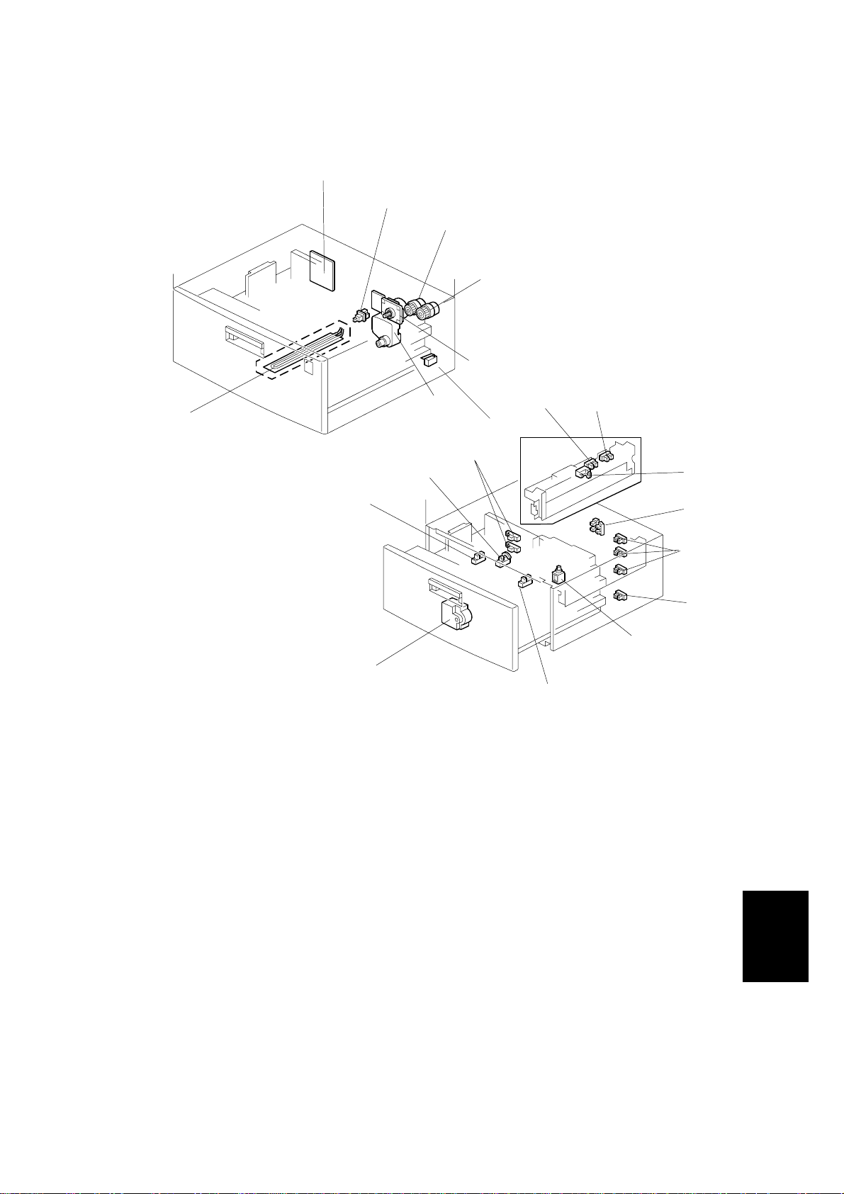
1.3 ELECTRICAL COMPONENT LAYOUT
1
2
3
4
5
7
A862D102.WMF
1. Main Board
2. Tray Sensor
17
16
6
89
20
19
18
14
A862D103.WMF
15
11. Side Fence Open/Closed Sensors
12. Paper Height Sensors 1, 2, 3
10
11
12
13
3. Relay Clutch
4. Paper Feed Clutch
5. Tray Motor
6. Tray Lift Motor
7. Tray Heater (option)
8. Right Tray Paper End Sensor
9. Upper Limit Sensor
10. Relay Sensor
A862-3
13. Lower Limit Sensor
14. Side Fence Solenoid
15. Rear Fence Return Sensor
16. Rear Fence Motor
17. Rear Fence Home Position
Sensor
18. Left Tray Paper End Sensor
19. Paper Height Sensors 4, 5
20. Right Cover Switch
Options
ELECTRICAL COMPONENT DESCRIPTIONS 20 September 1999
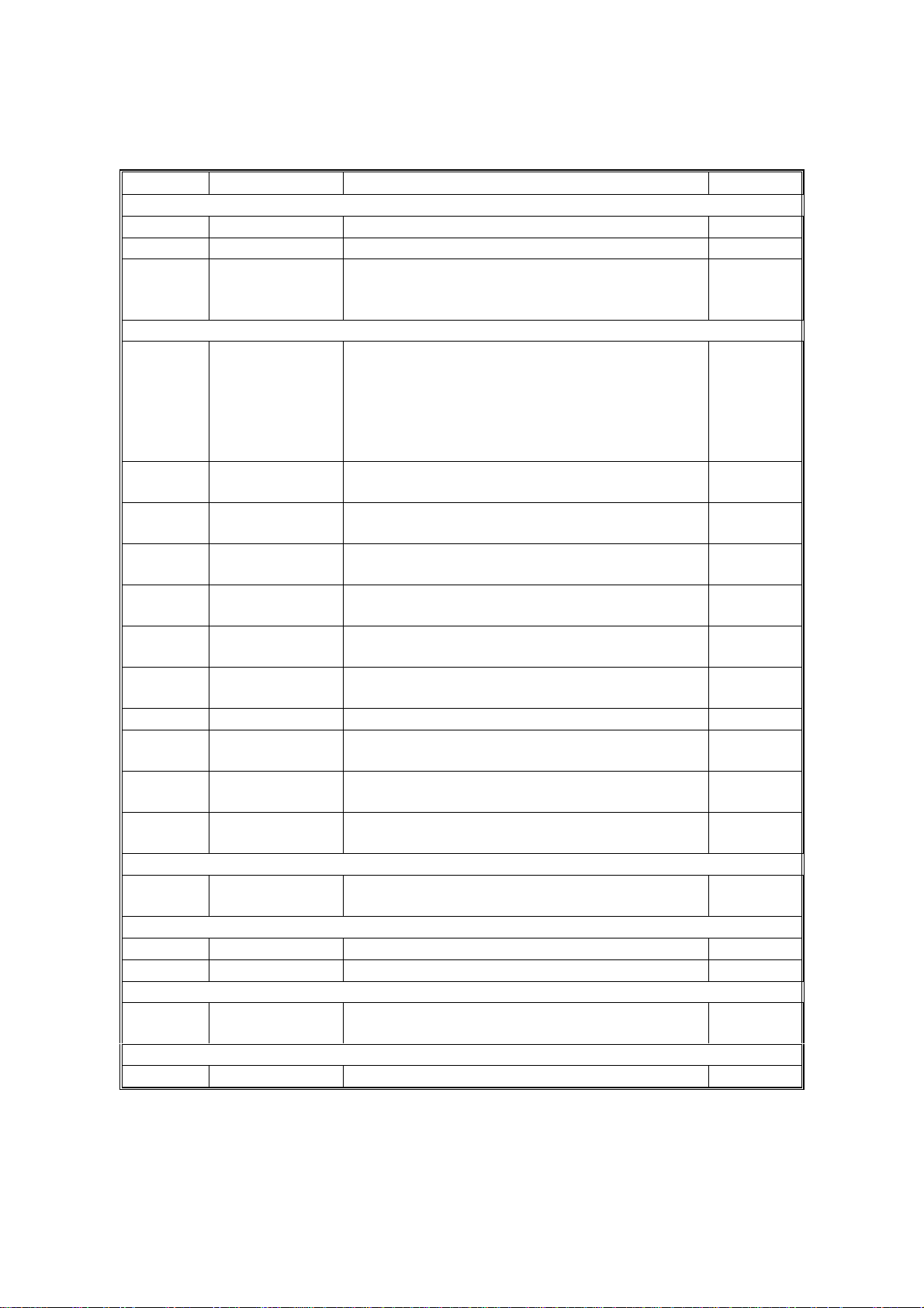
1.4 ELECTRICAL COMPONENT DESCRIPTIONS
Symbol Name Function Index No.
Motors
M1 Tray Motor Drives all rollers. 5
M2 Tray Lift Motor Drives the paper tray up or down. 6
Rear Fence
M3
Sensors
S1
S2
S3
S4
S5
S6
S7
S8 Tray Detects whether the tray is correctly set. 2
S9
S10
S11
Solenoids
SOL1
Magnetic Clutches
MC1 Paper Feed Drives the paper feed roller. 4
MC2 Relay Drives the relay roller. 3
PCBs
PCB1
Switches
SW1 Right Cover Detects whether the right cover is open. 20
Motor
Right Tray
Paper End
Relay
Upper Limit Detects when the paper is at the correct
Lower Limit Detects when the tray is completely lowered,
Paper Height
1, 2, 3
Paper Height
4, 5
Rear Fence
Home Position
Side Fence
Open/Closed
Rear Fence
Return
Left Tray
Paper End
Side Fence
Main Controls the LCT and communicates with the
Moves the rear fence to transfer the paper
stack from the paper storage (left) side of the
tray to the paper feed (right) side.
Informs the copier when the paper in the right
side (paper feed side) of the tray has been
used up. If there is a paper stack in the left
side (paper storage side), this is moved into
the right tray. If there is no paper stack in the
left side, paper end is indicated.
Detects the copy paper coming to the relay
roller and checks for misfeeds.
paper feed height.
to stop the LCT motor.
Detects the amount of paper remaining in the
right side of the tray.
Detects the amount of paper remaining in the
left side of the tray.
Detects when the rear fence is at H.P.
Detects whether the side fence is opened on
closed.
Detects when the rear fence has moved the
paper stack from the left side to the right side.
Informs the copier when there is no paper in
the left side (paper storage side) of the tray.
Controls open-close movement of the side
fence.
copier.
16
8
10
9
13
12
19
17
11
15
18
14
1
A862-4
20 September 1999 PAPER FEED
2. DETAILED SECTION DESCRIPTIONS
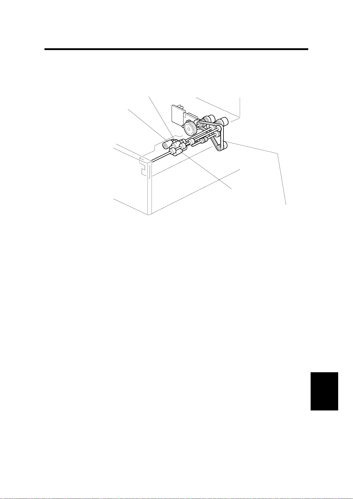
2.1 PAPER FEED
[B]
[A]
[C]
A862D104.WMF
This products uses an FRR type paper feed mechanism.
The paper feed unit consists of the pickup roller [A], paper feed roller [B], reverse
roller [C], and grip and transport rollers.
There is a torque limiter in the back of the reverse roller (ferrite powder type).
A862-5
Options
REVERSE ROLLER AND PICK-UP ROLLER RELEASE 20 September 1999
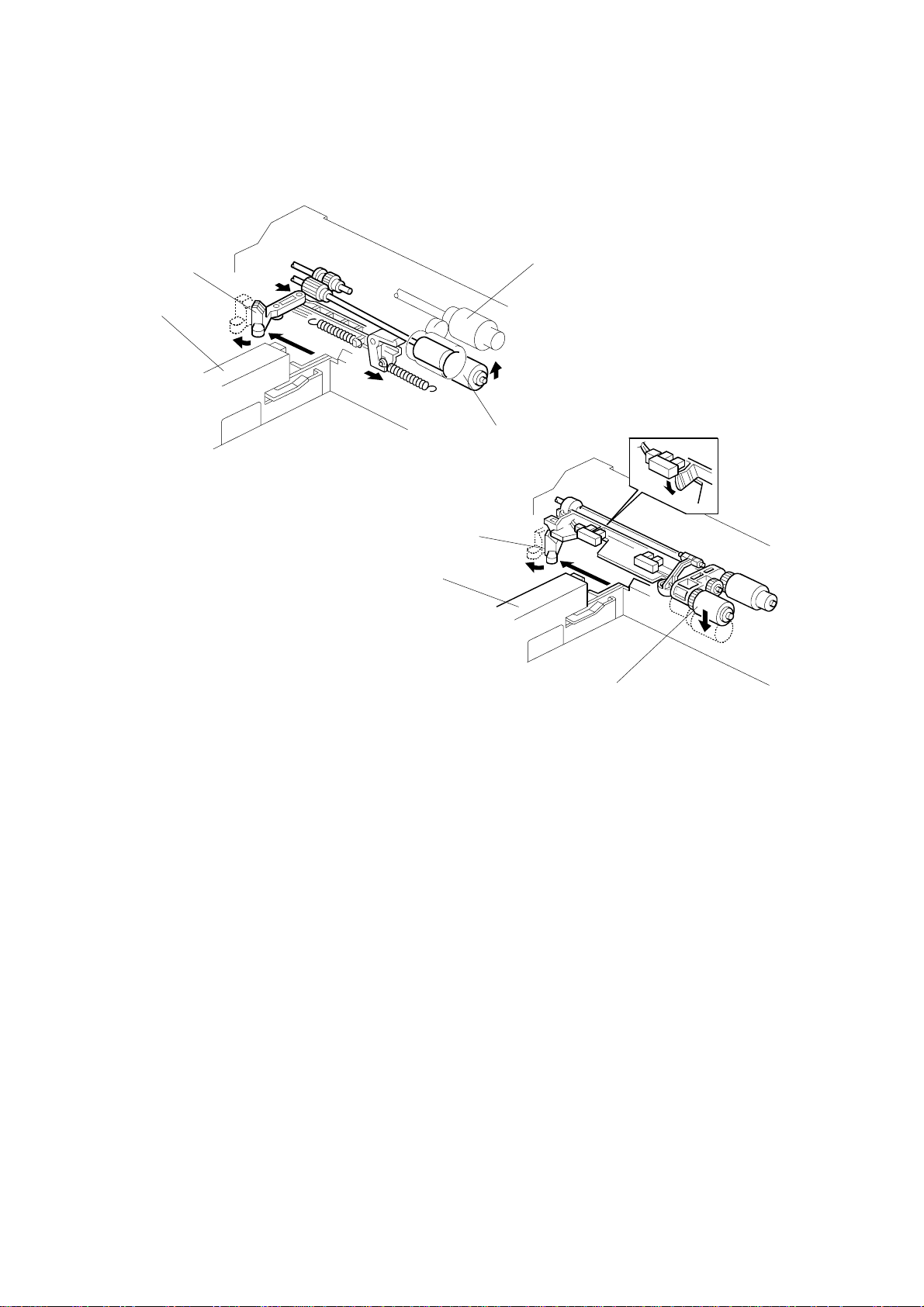
2.2 REVERSE ROLLER AND PICK-UP ROLLER RELEASE
[A]
[E]
[C]
[B]
A862D107.WMF
[E]
[A]
[D]
A862D108.WMF
To prevent the paper from being torn when pulling out the paper feed tray, the
reverse and pickup rollers are set so that they release automatically.
When the paper tray [A] is not inside the machine, the revers e roller [B] is away
from the paper feed roller [C] and the pick-up roller [D] stays in the upper position.
When the pa per tray is set into the m achine, it pushes the release lever [E]. This
causes the pick-up roller [D] to go down into contact with the top sheet of paper
and the reverse roller [B] to move up and contact the paper feed roller.
A862-6
 Loading...