

Page 1

PAPER TRAY UNIT
(Machine Code: A861)
Page 2

17 May, 1999 SPECIFICATIONS
1. OVERALL MACHINE INFORMATION
1.1 SPECIFICATIONS
Paper Size
Paper Weight: 60 ~ 105 g/m2, 16 ~ 28 lbs.
Tray Capacity: 500 sheets (80 g/m2, 20 lbs. ) x 1 tray
Paper Feed System: Feed roller and friction pad
Paper Height Detection: 4 steps (100%, 70%, 30%, Near end)
Power Source: 24 VDC and 5VDC (from the copier):
Power Consumption: Max:20 W (Copying)
Weight: 12 kg (26.4 lbs)
:
A5 to A3
HLT lengthwise to DLT
120 Vac:
120 V version, from the copier when the optional
tray heater is installed
220 ~ 240 Vac:
230 V version, from the copier when the optional
tray heater is installed
23 W (Optional Tray Heater On)
Average:13 W (Copying)
15 W (Optional Tray Heater On)
Size (W x D x H): 550 mm x 520 mm x 134 mm
Options
A861-1
Page 3
MECHANICAL COMPONENT LAYOUT 17 May, 1999
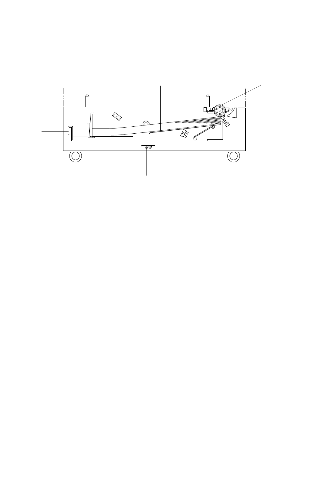
1.2 MECHANICAL COMPONENT LAYOUT
2
1. Paper Feed Roller
2. Tray
3
4
A861V101.WMF
1
3. Bottom Plate
4. Optional Tray Heater
A861-2
Page 4
17 May, 1999 ELECTRICAL COMPONENT LAYOUT
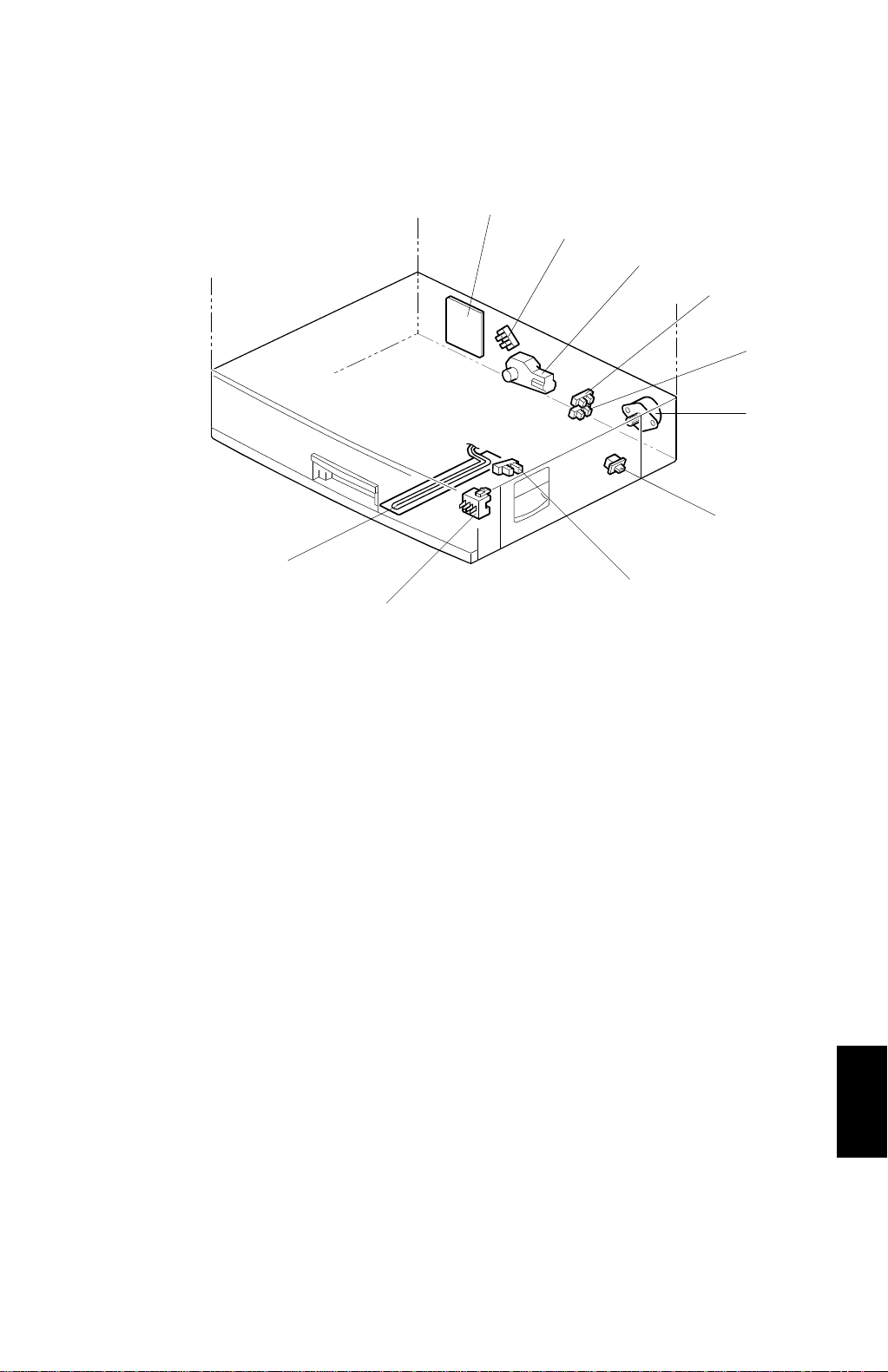
1.3 ELECTRICAL COMPONENT LAYOUT
1
2
3
4
5
6
7
10
8
9
A861V102.WMF
1. Tray Main Board
2. Lift Sensor
3. Lift Motor
4. Paper Height 2 Sensor
5. Paper Height 1 Sensor
6. Paper Feed Motor
7. Tray Cover Switch
8. Paper End Sensor
9. Paper Size Switch
10. Optional Tray Heater
Options
A861-3
Page 5

ELECTRICAL COMPONENT DESCRIPTION 17 May, 1999
1.4 ELECTRICAL COMPONENT DESCRIPTION
Symbol Name Function Index No.
Motors
M1 Paper Feed Drives the paper feed roller. 6
M2 Lift Lifts the tray bottom plate. 3
Sensors
S1
S2
S3 Paper Height 1 Detects the amount of paper in the tray. 5
S4 Paper Height 2 Detects the amount of paper in the tray. 4
Switches
SW1 Tray Cover Detects whether the tray cover is opened. 7
SW2 Paper Size Determines what paper size is in the tray. 9
Lift Detects when the paper in the tray is at the
correct feed height.
Paper End Informs the copier when the tray runs out of
paper.
2
8
PCBs
PCB1
Others
H1
Tray Main Controls the paper tray unit and communicates
with the copier.
Optional Tray
Heater
Removes humidity from the paper in the tray.
1
10
A861-4
Page 6
17 May, 1999 DRIVE LAYOUT
1.5 DRIVE LAYOUT
1
2
A861V103.WMF
1. Paper Feed Motor 2. Paper Feed Roller
Options
A861-5
Page 7
PAPER FEED AND SEPARATION 17 May, 1999
2. DETAILED DESCRIPTIONS
2.1 PAPER FEED AND SEPARATION
[A]
[B]
[C]
A861D103.WMF
The paper tray holds 500 sheets. The paper feed roller [A] drives the top sheet of
paper from the paper tray to the copier. The friction pad [B] allows only one sheet
to feed at a time. The friction pad applies pressure to the feed roller with a spring
[C].
A861-6
Page 8

1 October, 1999 PAPER LIFT MECHANISM
2.2 PAPER LIFT MECHANISM
[B]
[A]
[D]
[C]
[K] [G]
[F]
[H]
[A]
A861D106.WMF
[E]
[B]
[I]
[J]
[C]
[D]
[E]
A861D107.WMF
The SP modes mentioned in this section apply to A250 only, and not to G038.
The paper size switch detects when the tray is pushed in.
When the pa per tray is pushed into the mach ine, the pin [A] for the lift moto r
pressure shaft engages the lift motor coupling [B] and the pin [C] for the bottom
plate lift shaft in the tray engages the bottom plate pressure lever coupling [D]. The
pin [E] on the rear of the tray pushes the lock lever so that the lift motor can lift the
bottom plate pressure lev er .
The lift motor turns on, and turns clockwise as viewed on the diagram. The main
pressure spring [K] pulls the bottom plate pressure lever, and this lifts the tray
bottom plate.
When the top of the stack touches the feed roller, the motor cannot pull up the
plate any more, so it pulls the actuator [G] into the lift sensor [F].
The pressure of the feed roller on the paper is now too high, so the lift motor
reverses to reduce this pressure. It reverses for 300 ms or 600 ms, depending on
the paper size. For smaller paper, it reverses the larger amount (600 ms) to reduce
the pressure more.
When the paper tray is pulled out, t he pins [A, C] disenga ge from the couplings [B,
D], and the bottom plate drops. To make it easier to push the tray in, the lift motor
rotates backwards 1.7 seconds to return the bottom plate pressure lever coupling
[D] to the original position.
Options
A861-7
Page 9

PAPER LIFT MECHANISM 17 May, 1999
The paper size thresholds for this feature depend on SP1-908-8 and 9. (Note that
there are two paper size thresholds: small and middle. Some models only use the
small threshold.) The amount of reverse depends on SP 1-908-1, 2, and 3. (See
the table later in this section for details of how these SP modes work.)
For A4-width paper or wider, a projection [H] on the side fence engages the
secondary pressure spring [J] through a lever [I] . Then, the secondary pressure
spring [J] applies paper feed pressure in addition to the main pressure spring [K], to
ensure that extra pressure is applied to wider paper.
As stated earlier, various SP modes control this mechanism. The following table
summarizes them.
No Middle Size Programmed
(Default for A250)
Paper width:
More than 1-908-8
(Default: Wider than HLT)
Amount of reverse:
1-908-1
(Default 300 ms)
Paper width:
1-908-8 or less
(Default: HLT or narrower)
Amount of reverse:
1-908-2
(Default: 600 ms)
With Middle Size Programmed
Paper width:
More than 1-908-9
Amount of reverse:
1-908-1
Paper width:
More than 1-908-8, up to and
including 1-908-9
Amount of reverse:
1-908-3
Paper width:
1-908-8 or less
Amount of reverse:
1-908-2
When the paper tray is pulled ou t, the pins [A, C] disengage from the couplings [B,
D], and the bottom plate drops. To make it easier to push the tray in, the lift motor
rotates backwards 1.7 seconds to return the bottom plate pressure lever coupling
[D] to the original position.
A861-8
Page 10

17 May, 1999 PAPER END DETECTION
2.3 PAPER END DETECTION
[A]
[B]
[C]
A861D105.WMF
If there is some paper in the paper tray, the paper stack raises the paper end feeler
[A] and the paper end sensor [B] is deactivated.
When the paper tray runs out of paper, the paper end feeler drops into the cutout
[C] in the tray bottom plate and the paper end sensor is activated.
When the paper tray is drawn out with no paper in the tray, the shape of the paper
end feeler causes it to lift up.
A861-9
Options
Page 11

PAPER HEIGHT DETECTION 1 October, 1999
2.4 PAPER HEIGHT DETECTION
[B]
[A]
[C]
[C]
A861D107.WMF
The SP modes mentioned in this section apply to A250 only, and not to G038.
The amount of paper in the tray is detected by the combination of on/off signals
from two paper height sensors [A] and [B].
When the amount of paper decreases, the bottom plate pressure lever [C] moves
the actuator up.
The following combination of sensor signals is sent to the copier.
Amount of Paper Paper Height Sensor 1 Paper Height Sensor 2
Near End OFF ON
30% ON ON
70% ON OFF
100% OFF OFF
When the tray contain s paper of a small width, the paper feed pressure may
become too low when the thickness of the stack of remaining paper has
decreased. The lift motor rotates forward 300 ms after the sensor detects a certain
amount of paper remaining in the tray to increase paper feed pressure, simulating
the pressure generated by a full tray.
The amount of remaining paper depends on SP modes 1-908-6 and 7. The amount
of forward rotation depends on SP1-908-4 and 5. Note that there are two paper
size thresholds: small and middle (this is the same as for the paper lift mechanism
described earlier). Some models only use the small threshold. The paper size
thresholds depend on SP1-908-8 and 9.
A861-10
Page 12

17 May, 1999 PAPER HEIGHT DETECTION
The following table summarizes how these SP modes work.
No Middle Size Programmed
(Default for A250)
Paper width:
More than 1-908-8
(Default: Wider than HLT)
Amount of forward rotation:
None
Paper width:
1-908-8 or less
(Default: HLT or narrower)
Amount of remaining paper:
1-908-6
(Default: W hen near-end is
detected)
Amount of forward rotation:
1-908-4
(Default: 300 ms)
With Middle Size Programmed
Paper width:
More than 1-908-9
Amount of forward rotation:
None
Paper width:
More than 1-908-8, up to and
including 1-908-9
Amount of remaining paper:
1-908-7
Amount of forward rotation:
1-908-5
Paper width:
1-908-8 or less
Amount of remaining paper:
1-908-6
Amount of forward rotation:
1-908-4
Options
A861-11
Page 13

PAPER SIZE DETECTION 17 May, 1999
2.5 PAPER SIZE DETECTION
Size
1/2
1/2
1/2
" x 14"
" x 11"
1/2
" x 13")
"
A3, F (8
A4 Lengthwise
A4 Sideways
A5 Sideways,
11" x 17"
B4, 8
B5 Sideways,
8
B5 Lengthwise,
11" x 8
* (Asterisk)
SW
1234
lll
l
m
l
ll
l
m
mmmm
mm
mm
l
: ON (Not pushed)
m
: OFF (Pushed)
m
l
m
mm
mm
mm
l
m
ll
[B]
[A]
A861D108.WMF
There are four paper size microswitches [A] on the front right plate of the paper tray
unit. The switches are actuated by a paper size actuator [B] behind the paper size
indicator plate, which is on the front right of the tray.
Each paper size has its own actuator, with a unique combination of notches. To
determine which size tray has been installed, the CPU reads which microswitches
the actuator has switched off.
The CPU disables paper feed from a tray if the paper size cannot be detected. If
the paper size actuator is broken, or if there is no tray installed, the Add Paper
indicator will light.
When the paper size ac tuator is at the "*" mark, the paper tr ay can be set u p to
accommodate one of a wider range of paper sizes by using user tools. If the paper
size for this position is changed without changing the user tool setting, a paper jam
will result.
A861-12
Page 14

17 May, 1999 SIDE AND END FENCES
2.6 SIDE AND END FENCES
[A]
[D]
[B]
A861D110.WMF
[C]
A861D109.WMF
Side Fences
If the tray is full of paper and it is pushed in strongly, the fences may deform or
bend. This may cause the paper to skew or the side-to-side registration to be
incorrect. To correct this, each side fence has a stopper [A] attached to it. Each
side fence can be secured with a screw [B], for customers who do not want to
change the paper size.
End Fence
As the amount of paper in the tray decreases, the bottom plate [C] lifts up
gradually. The end fence [D] is connected to the bottom plate. When the tray rises,
the end fence moves forward and pushes the back of the paper stack to keep it
squared up
A861-13
Options
Page 15

FEED ROLLER REPLACEMENT 17 May, 1999
3. REPLACEMENT AND ADJUSTMENT
3.1 FEED ROLLER REPLACEMENT
[C]
[B]
A861R723.WMF
1. Remove the paper tray [A].
2. Move the release lever [B] to the front.
3. Pull the feed roller [C] to the operation side and remove it.
4. Replace the feed roller.
[A]
A861-14
Page 16

17 May, 1999 TRAY MAIN BOARD REPLACEMENT
[A]
A861R151.WMF
[C]
3.2 TRAY MAIN BOARD REPLACEMENT
1. Remove the rear cover [A] (4 screws).
2. Replace the tray main board [B] (4 screws and 8 connectors).
3.3 TRAY MOTOR REPLACEMENT
1. Remove the rear cover (4 screws).
[B]
A861R103.WMF
2. Disconnect 8 connectors on the tray main board [B].
3. Remove the tray main board with the bracket (2 screws).
4. Remove the tray motor [C] (6 screws and 1 connector).
A861-15
Options
Page 17

TRAY MOTOR REPLACEMENT 17 May, 1999
3.4 TRAY MOTOR REPLACEMENT
[B]
[A]
A861R102.WMF
1. Remove the rear cover [A] (4 screws).
2. Replace the tray motor [B] (2 screws and 1 connector).
A861-16
Page 18

17 May, 1999 LIFT MOTOR REPLACEMENT
3.5 LIFT MOTOR REPLACEMENT
[A]
A861R102.WMF
[C]
1. Pull out the paper tray.
2. Remove the rear cover [A] (4 screws).
3. Disconnect the 2P connector [B].
4. Remove the spring [C].
5. Remove the lift motor unit [D] (3 screws).
6. Remove the lift motor [E] (2 screws).
[D]
[B]
[E]
A861R104.WMF
A861-17
Options
Page 19

PAPER END SENSOR REPLACEMENT 17 May, 1999
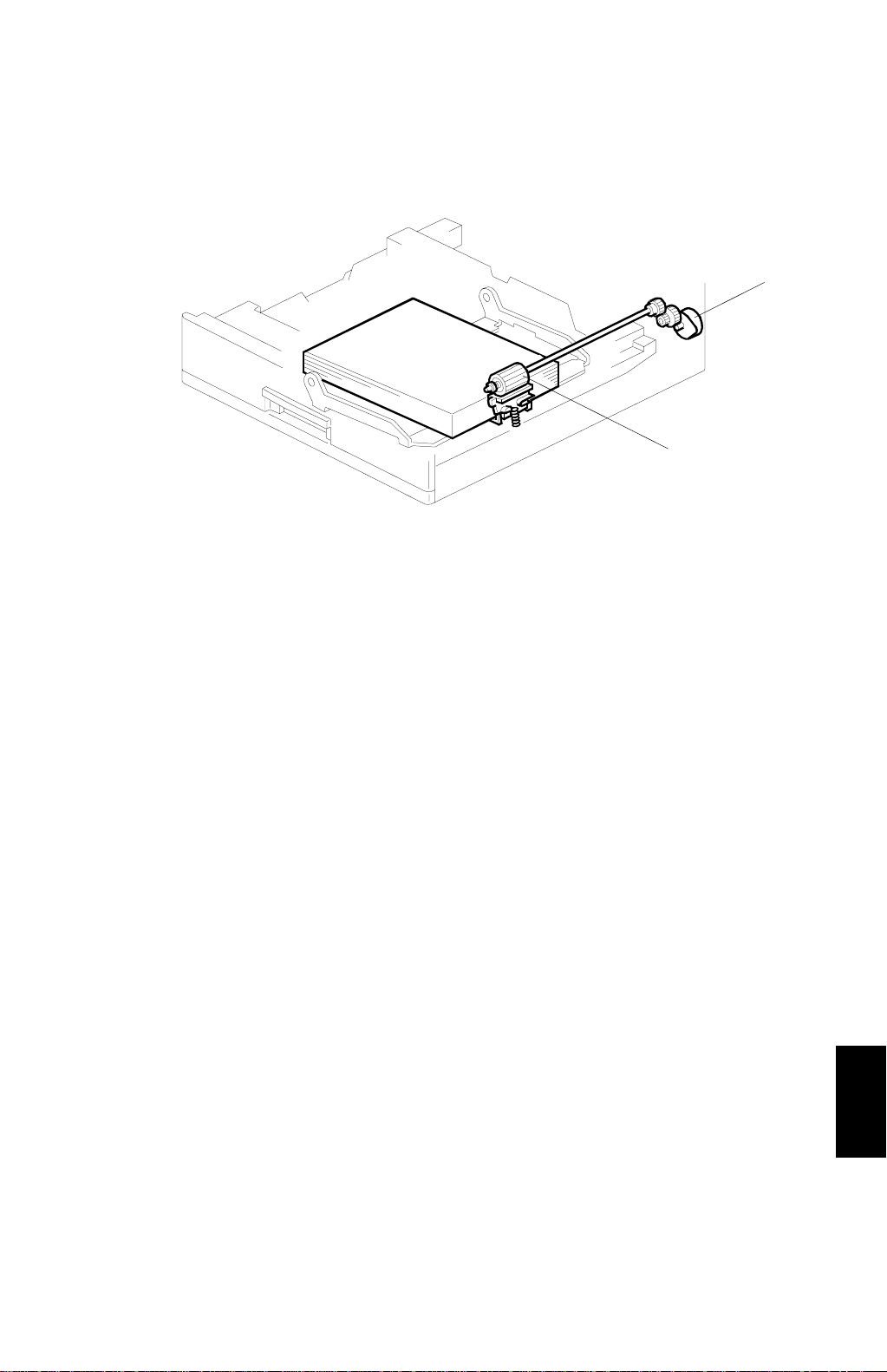
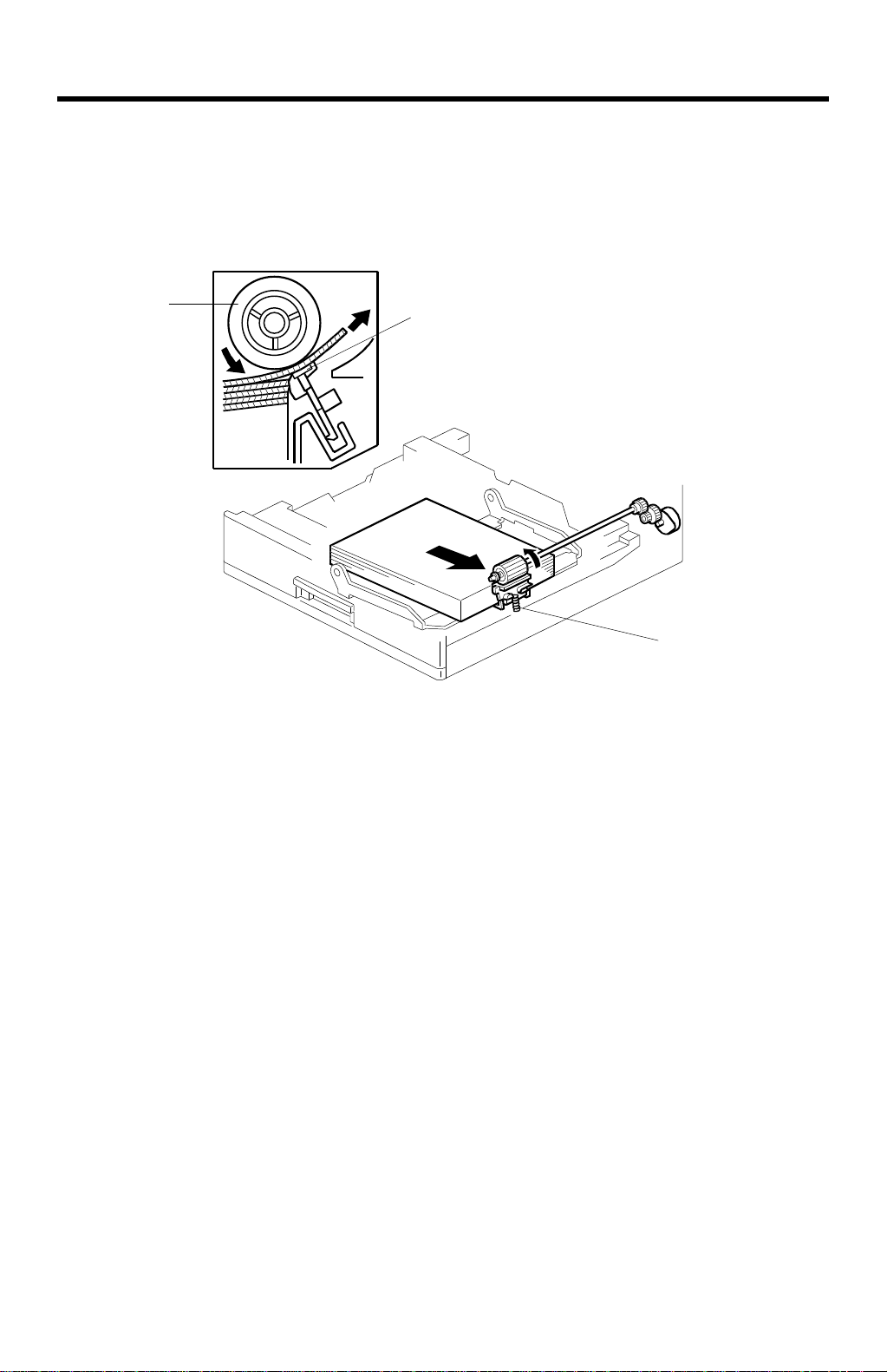
3.6 PAPER END SENSOR REPLACEMENT
[C]
[B]
[A]
A861R106.WMF
1. Remove the paper tray.
2. Remove the paper end sensor bracket [A] (1 screw and 1 connector).
3. Replace the paper end sensor [B].
NOTE:
After replacing the sensor, pull the sensor harness to the right side of the
frame [C] so that the harness does not touch the paper in the tray.
3.7 PAPER SIZE SWITCH REPLACEMENT
[D]
[E]
[B]
[A]
A861R101.WMF
[C]
1. Remove the lower tray cover [A] (2 screws).
2. Remove the paper tray [B].
3. Remove the right front cover [C] (1 screw).
4. Remove the paper size switch bracket [D] (1 screw).
5. Replace the paper size switch [E].
A861-18
Page 20

ELECTRICAL COMPONENT LAYOUT (A250/A859/A860/A861/A869)
- A250 -
37
36
35
34
33
32
31
30
29
3
2
1
262728
4
5
2122232425
A250S152.WMF
- A250 -
Symbol Index No. Description P to P
Motors
M1 4 Scanner K2
M2 28 Polygonal Mirror C8
M3 12 Main G2
M4 46 Exhaust Fan B2
Magnetic Clutches
MC1 14 Paper Feed F2
MC2 15 By-pass Feed C2
MC3 18 Vertical Transport F2
MC4 13 Registration B2
Switches
SW1 40 Main B7
SW2 30 Right Door Switch 1 A2
SW3 31 Right Door Switch 2 A2
SW4 25 Vertical Transport Cover Switch B2
SW5 24 Paper Size L2
Sensors
S1 3 Scanner HP K2
S2 37 Original Width J2
S3 6 Original Length 1 I2
S4 6 Original Length 2 I2
S5 21 Toner Near-E nd B2
S6 23 Paper End B2
S7 19 Paper Near-End C2
S8 16 By-pass Tray Paper D2
S9 20 B y-pass Paper Size D2
S10 22 Vertical Transport E2
S11 17 Regis tration D2
S12 35 Fusing Exit A4
S13 27 Exit Tray Paper E2
S14 5 Platen Cover J2
S15 33 AIO Set L2
PCBs
PCB1 44 BICU E9
PCB2 39 PSU C7
PCB3 45 IOB E3
PCB4 8 SBU C9
PCB5 7 Lamp Stabilizer J2
PCB6 26 LD Unit C8
PCB7 36 Operation Panel E10
PCB8 — Memory (option) G9
PCB9 42 Printer Controller (option) G9
PCB10 43 FCU (Option) F10
PCB11 47 NCU (option) —
- A250 -
6
7
8
9
10
11
12
13
14
15
16
17
18
19
20
47
47
46
45
44
42
43
- A250 -
Symbol Index No. Description P to P
Lamps
L1 2 Exposure Lamps J2
L2 10 Fusing Lamp A5
Heaters
H1 1 Anti-Condensation A6
H2 — Drum (option) A6
Others
TF1 9 Fusing Thermofuse A5
TH1 11 Fusing Thermistor A4
PP1 3 8 C/B/T H2
LSD 1 29 Laser Synchronization Detector C9
CO1 48 Total F2
CO2 — Key (option) L1
LED1 32 Exit Tray E 2
LED2 34 1-bin Tray F2
SP1 41 Speaker —
- A869 -
6
A250S153.WMF
1
5
4
- A869 -
Symbol Index No. Description P to P
Motors
M1 1 Tray M1
Sensors
S1 6 Exit N1
S2 5 Paper N1
Switches
SW1 4 B i n Tray N1
PCBs
PCB1 2 1 Bin Tray N2
LEDs
LED1 7 1 Bin Exit Tray F2
Solenoid
SOL1 3 Junction Gate M1
A869S103.WMF
38
39
40
41
2
3
19
18
- A860 -
20
1
17
16
15
14
- A860 -
Symbol Index No. Description P to P
Motors
M1 20 Tray L8
M2 3 Upper Lift N8
M3 18 Lower Lif t M8
Sensors
S1 2 Upper Lift M8
S2 19 Lower Lif t M8
S3 13 Upper Paper End J8
S4 14 Lower Paper End J8
S5 12 Vertical Transport I8
S6 15 Upper P aper Size I8
S7 16 Lower P aper Size I8
S8 5 Upper Paper Height 1 H8
S9 4 Upper Paper Height 2 H8
S10 11 Lower Paper Hei ght 1 G8
S11 10 Lower Paper Hei ght 2 G8
Switches
SW1 8 Tray C over J 8
Magnetic Clutches
MC1 6 Upper Paper Feed J8
MC2 9 Lower Paper Feed K8
MC3 7 Relay K8
PCBs
PCB1 1 Tray Main K7
Others
H1 17 Option Tray Heater N8
1
- A861 -
10
9
2
12
13
A860S102.WMF
2
A861S102.WMF
- A859 -
3
4
5
12
13
6
11
7
8
9
10
10
11
- A859 -
Symbol Index No. Description P to P
Motors
M1
Sensors
S1
S2
S3
S4
S5
S6
S7
S8
Solenoids
SOL1
SOL2
Clutches
MC1
PCBs
PCB1
3
- A861 -
4
Symbol Index No. Description P to P
5
6
7
8
Motors
M1 6 Paper Feed J6
M2 3 Lift H6
Sensors
S1 2 Lift G6
S2 8 Paper End H6
S3 9 Paper Size I6
S4 5 Paper Height 1 H6
S5 4 Paper Height 2 H6
Switches
SW1 7 Tray C over I6
PCBs
PCB1 1 Tray Main H5
Others
H1 10 Option Tray Heater J6
9 DF Transport
6DF Open
13 Registration
2 Feed Cover Open Sensor
3 Original Width
8 Original Length 1
7 Original Length 2
11 Original Set
12 Original Trailing Edge
4DF Pick-up
10 Stamper
1DF Feed
5DF Drive
1
2
3
4
5
6
K6
M6
L6
M6
M6
N6
N6
L6
N6
L6
K6
K6
M5
8
9
A859S102.WMF
7
Page 21

ABC
A250 Point to Point Diagram
1
Paper
Near End
Sensor
-2-3-4
s
t
[5]
[5]
GND [0]
t
[0] GND
[ 5] New Fusing Unit
FU5 FU6
FU2
FU4
PSU (PCB2)
CB
FU1
CN221-1
Registration
Clutch
CN310-1-2CN311-1-2CN309-1
+24V [24]
[24] +24V
[24] +24V.M
-2-3-4
CN305-1
-2-3-4
CN285-1
Polygonal Mirror
-2
-3
SBU
2
3
4
Fusing
Thermister
Fusing Exit
Sensor
Fusing Thermofuse TF1
5
Anti-condensation
6
7
8
9
10
Right
Door
Door
Switch 1
Switch 2
SW2 SW3 SW4
-5-4-3-2-1
CN306-6
t
+5V [5]
LD5VS [ 5]
s
[ 24] SW On
[24] +24V
-2
CN304-1
J K
B7
T
S12
Fusing Lamp L2
J5/N7
Drum Heater
Heater
(230V version only)
Main Switch
Power Supply Cord
*1 *2 *3
230V Machine
115V Machine
Right
t
24V.S [ 24]
H1
Transport
+24V [24]
V
W
Coil
G10
Vertical
Exhaust
Cover
Fan Motor
Switch
CN319-1-2CN322-1
t
+24V [24]
+24V [24]
24V.S2 [ 24]
H2
H1
SW1
X
Y
*1 *2 *3
230V
230
s
115V
115
s
Paper
Toner
Sensor
Sensor
-2
-4
t
[5]
+5V [5]
[0] GND
Fusing Termister
[0] GND
[*2] Fusing Lamp - H
[*2] Fusing Lamp - N
[*3] AC - H
[*3] AC - H
[*3]
[*3]
[*3]
[*3]
[*3]
[*3]
[*2] AC - H
[*2] AC - H
[*2] SW ON - H
[*2] SW ON - N
[*1] AC - H
[*1] AC - N
End
CN325-1
GND [0]
[ 5] Fusing Exit Sensort[5] +5V
FU3
Near End
t
[ 24]
GND [0]
[ 5] Fusing Unit Sett[0] GND
-1-2-3-4-5-6-7-8-9
CN303
CN282-1
-2
CN283-1
-2
-3
-7
-5
-9
-4
-8
CN289-1
-2
CN281-4
-3
-2
-1
J
A4
K
CN287-2
[5] +5V
-1
230V Machine
[0] GND
T280
[*1] AC - H
T281
[*1] AC - N
115V Machine
230
t
115
t
LSD1
Laser
Synchronization
Detector
t
[ 24]
[0] PGND
RA
+12V [12]
-12V [-12]
GND [0]
GND [0]
AGND [0]
+24V [24]
Motor
[5]
t
[5] +5V.D
[0] GND
By-pass
Paper Feed
Clutch
+24V [24]
[5] +5V
[0] GND
-5
-5
+5V [5]
+5V [5]
M2
LD Unit
PCB6
PCB4
Registration
t
[ 24]
CN284-5
CN286-8
Sensor
-2-3-4-5-6
t
[5]
+5V [5]
GND [0]
-2-3-4
CN304-1
-4
-3
-2
-1
-7
-6
-5
-4
-3
-2
-1
CN220
CN200
By-pass
Tray
Paper
Sensor
GND [0]
[ 24] Relay Ont[ 24] Fusing Lamp OntZero Cross
CN104-1
CN112-1
t
[5]
[0] GND
D
+5V [5]
[24] +24V.S1
-5
-2
-3
-4
-5
-6
-7
-8
-2
-3
-4
-5
Paper Size
CN321-1
t
[24] +24V
[0] GND
[ 24] ON
[ 24] Ready
CLOCK
CN111
CN102
By-pass
Sensor
-2-3-4-5-6-7-8
Size 4 [ 5]tSize 3 [ 5]
Vertical
Transport
Sensor
t
t
[5]
GND [0]
GND [0]
Size 2 [ 5]tSize 1 [ 5]
IO Board
PCB3
t
t
[ 5] LED Ont[ 5] Beepert[ 5] Power Keyt[ 5] Pre-heat Key
[-12] -12V
LED
-2
-3-5-4
CN103-1
Operation Panel (PCB7)
EF
Paper
Sensor
GND [0]
Exit Tray LED
1-bin
Copier
Tray
LED1
LED2
-10
-11
-12
-13
-14
-15
t
[5]
+5V [5]
t
[5]t[5]
+5V [5]
+5V [5]
CN301
CN105
Vertical
Paper
Transport
Feed
Clutch
CN307-1-2CN308-1-2CN317-1-2CN309-7
t
[ 24]
+24V [24]
Clutch
+24V.S2 [24]
Total
Counter
t
[ 24]
+24V [24]
Exit Tray
-9
+5V [5]
CN105
1 /IOBCNT2 16 GND 3 1 +5V S 46 GND
2 FUTMP 17 /IOWR 32 GND 4 7 /IORD
3 MCCFB 18 GND 33 BIV FB 4 8 /IOCS
4 TCCFB 1 9 GND 3 4 MCVFB 4 9 GND
5 PCUTEMP 2 0 /IORST 35 TCV FB 5 0 IOCLK
6 GND 21 GND 36 GND 51 GND
7/INTZERO 22SMO8 37GND 52SMO9
8 IOD14 23 SMO6 38 IOD15 53 SMO7
9 IOD12 24 SMO4 39 IOD13 54 SMO5
10 IOD10 2 5 SMO2 40 IOD11 55 SMO3
11 IOD8 26 SMO0 41 IOD9 56 SMO1
12 GND 27 /KCNTO K 42 GND 57 PTRSV I
13 IOA5 28 KEYRXD 43 IOA6 58 KEYTXD
14 IOA2 29 DFRXD 44 IOA3 59 DFTXD
15 IOA0 30 /DFGATE 45 IOA1 60 IOBCNT1
CN111
1 +5V 11 LDDAXD 21 /PCLK 31 GND
2 +5V 12 LDDWXR 22 /PFGATE 32 +5V S
3 GND 13 LDOFF 23 GND
4 GND 14 /L DERR 24 /LDSY NC
5 /BD 15 PSO 25 PSE
6REFCLK 16/PDO0 26/PDE0
7 LDDCLK 17 /PDO1 2 7 /PDE1
8 LDDDI 18 /PDO2 28 /PDE2
9 LDDDO 19 /PLGA TE 29 /VDTHRU
10 /DEVRST2 20 /PLSYNC 30 GND
CN102
1 GND 16 SDO1 31 SDE2 46 GND
2 +5V 17 SDO2 32 SDE3 47 GND
3 +5V 18 SDO3 33 GND 48 -12V
4 +5V 19 GND 34 SDE4 49 - 12V
5 +5V 20 SDO4 35 SDE5 50 GND
6 +5V 21 SDO5 36 SDE6
7 GND 22 SDO6 37 SDE7
8 +12V 23 SDO7 38 GND
9 +12V 24 GND 3 9 /SSCA N
10 +12V 25 GND 40 /SLEAD
11 /R D SYNC 26 /SCLK 41 GND
12 /SHGATE 27 GND 42 SBUDI
13 /OPBSYNC 28 GND 43 SBUD O
14 GND 29 SDE0 4 4 SBUCLK
15 SDO0 30 SDE1 45 SBULATCH
BICU
(PCB1)
t
[0] GND
[0] GND
CLOCK
DATA IN
DATA OUT
[5] +5V
-6-7-8
[5] +5V
-9
-10
-11
-12
-13
CN113
CN
FCU (PCB10)
t
[ 24]
CN114
GH I JK LMN
1-Bin Tray (A869)
Junction
Paper
Gate
Solenoid
SOL
1
-6
CN404-1
t
t
B [24 24/0]
/B [24 24/0]
-2-3-4-5-6-7-8
-2-3-4-5-6-7-8
t
Tray Motor On [ 5]
t
+24V [24]
+24V [24]
+24V [ 24]
t
t
t
t
Connect [ 5]
Door Close [ 5]
Exit Sensor [ 5]
Paper Sensor [ 5]
Sensor
-2-3-4-5-6
CN402-1
t
[5]
GND [0]
1-Bin Tray Board
-9
-9
+5V [5]
GND [0]
PGND [0]
Direction [5:CCW / 0: CW]
Tray Motor
Platen
Cover
Power Pack - B/C/TMain Motor
Original Length
Sensor 2
Original Length
Sensor 1
Original Width
Sensor
M3MC1 MC3 CO1
-8
-9
-10
-11
s
t
GND [0]
GND [0]
On [ 5]
Lock [ 5]
-12
-13
CN302-3
+24V.S1 [24]
+24V.S1 [24]
t
[ 24] 3rd Paper F. MC (A860)t[ 24] Transport MC (A860)
[ 24] 2nd Paper F. MC (A860)t[ 24] Paper Feed Motor (A861)
-A2
-A3
CN312-A1
-A13
-A14
CN100-A15
-4-5-6-7-8
t
t
+24V.S1 [24]
Bias On [ 5]
PWM - Bias [0 0/5]
t
[0/5] Scan B (A860/A861)
[0/5] Scan A (A860/A861)
-A4
-A5
-A11
-A12
+5V [5]
GND [0]
[0/5] Paper Height (A860/A861)
[0/5] Set Bank (A860/A861)
-A6
-A7
-A9
-A10
FB-B.V.
[0/5] 3rd Paper Size (A860)
-A8
-A8
-9
[0/5] 2nd Paper Size (A860)
-A9
-A7
t
PWM-C[0 0/5]
[0/5] Paper Size (A861)
-2-3-4
-5
GND [0]
Length 3 [ 5]tLength 4 [ 5]
[0] GND (A860/A861)
[24] +24V (A860/A861)
-B3
-B4
-B12
-B13
CN320-1
t
Sensor On [ 5]
[24] +24V (A860/A861)
-B5
-B11
-2-3-4-5-6-7-8
t
t
+5V [5]
[0] GND (A860/A861)
[24] +24V (A860/A861)
-B6
-B7
-B9
-B10
GND [0]
Length 1 [ 5]tLength 2 [ 5]
t
[5] +5V (A860/A861)
[ 5] Motor Rotate (A860) / [0] GND (A861)
-B8
-B9
-B7
-B8
+5V [5]
Sensor On [ 5]
[0] GND (A860/A861)
[ 5] Tray Motor (A860)t[ 5] 3rd Lift Motor (-) (A860)
-B10
-B11
-B5
-B6
-10
-11
-12
-13
-14
CN324-1
t
FB-C.V.
Charge On [ 5]
t
[ 24] Relay Clutch (A860)
Not Used
-A10
-A11
-A5
-A6
-A12
-A4
FB-T.C.
s
[ 5] Lower Lift Sensor (A860)
t
PWM - T. C. (-) [0 0/5]
s
[ 5] Upper Lift Sensor (A860)s[ 5] Lift Sensor (A861)
-A13
-A3
t
t
t
+5V [5]
Sensor On [ 5]
PWM - T. C. (+) [0 0/5]
s
[0] GND (A860/A861)
[0] GND (A860/A861)
[ 5] Paper End Sensor (A861)s[ 5] Upper Paper End Sensor (A860)s[ 5] Lower Paper End S. (A860)
-B1
-B2
-A14
-A15
-A2
-A1
-B14
-B15
Tray Main Board (PCB1)
Exposure
Lamp
S2S5
t
Width 2 [ 5]
t
-B12
-B4
-9
t
Width 1 [ 5]
t
[ 5] 3rd Lift Motor (+) (A860)
-B13
-B3
Stabi-
lizer
-10
CN327-1
GND [0]
+24V [24]
t
[ 5] 2nd Lift Motor (-) (A860)t[ 5] Lift Motor (-) (A861)t[ 5] 2nd Lift Motor (+) (A860)t[ 5] Lift Motor (+) (A861)
-B14
-B15
-B1
-B2
L1
-2
GND [0]
Sensor
-3
-4-5-6-7-8
s
t
GND [0]
Close [ 5]
Lamp On[ 24]
[5] +5VE
DFGATE
-A2
CN314-A1
-7-6-5-4-3-2-1
CN120-8
Scanner HP
Sensor
S1S14S3S4PP1S13S10S9S8S11S7S6
+5V [5]
GND [0]
[0] GND
-A3
-A4
[0] GND
s
[5]
[0] GND
-A5
-9
+5V [5]
-A6
CN318-1
+24V [24]
[24] +24V.M
-A7
Scanner Motor
M1
-2-3-4-5-6
t
+24V [24]
A [24 24/0]
[24] +24V.M
[24] +24V.M
-A8
t
/A [24 24/0]
t
B [24 24/0]
t
/B [24 24/0]
Paper Size
Switch
-2-3-4-5-6
CN323-1
t
[5]t[5]
GND [0]
CN314-B1
CN130-9
t
[5]
[5] +5V
AIO Set
CO2
Sensor
S15SW5MC2MC4M4
CN326-4
t
GND [0]
Set [ 5]
[5] +5V
[0] GND
[0] GND
TXD
-B2
-B3
-B4
-B5
-8-7-6-5-4
Key Counter
-2-3-1
t
[ 24]
+24V [24]
[0] GND
RXD
-B6
-B7
-3
t
GND [0]
Set [ 5]
M1
-2-2-3-4-5
CN403-1
t
t
+24V [24]
A [24 24/0]
/A [24 24/0]
CN401-1
CN315-1
t
Junction Gate Solenoid On [ 5]
Document Feeder (A859)
DF Drive Board (PCB1)
[24] +24V
[24 24/0] At[24 24/0] /At[24 24/0] /Bt[24 24/0] B
-2
-4-6-5
M1
DF Transport
Motor
t
-7-8-9
Stamper
Solenoid
[24] +24V
SOL
[5] +5V
Original
Length 1
Sensor
[5]t[0] GND
-6-7-8
t
[5]t[5] +5V
[ 5] LED On
-9
Original
Length 2
Sensor
[ 24]t[24] +24V
-11
[24] +24V
CN260-1
SOL
1
DF Pick-up
Solenoid
t
[ 24]
-2
Registration
[0] GND
CN210-1
Sensor
t
[ 24]
-10
MC1
2
DF Feed
Clutch
t
t
[5]
[0] GND
[0] GND
[5] +5VE
[5] +5V
[5]
-2
-3-5-4
-6-7-8
Original
Set
Open
Sensor
Sensor
s
s
[0] GND
[5] +5V
[5]
[5]
-9
-11
-12
DF
Feed Cover
Open
Sensor
t
[5] +5V
[0] GND
[ 5] Width 1t[ 5] Width 2
-2
-3-5-4
-13
CN230-1
Original
Width
Sensor
t
t
t
t
-5
M2
Lift
s
[0] GND
[0] GND
[5] +5V
[5]
-2-3-4-5-6-7-8
CN102-1
Paper
Paper
Height 1
Height 2
Sensor
Sensor
s
[ 24] (+)t[ 24] (-)
[5] +5V
[0] GND
[5]
-2-3-4
CN105-1
S1 S4 S3 S2 SW2 H1 S2 S7 S1 S3 S4 S5 S6 S8
Lift
Motor
Sensor
s
s
[5] +5V
[5]
[0] GND
Paper
End
Sensor
[5] +5V
[5]
-9
[ 5] Size 1t[ 5] Size 2t[ 5] Size 3t[ 5] Size 4
CN103-1
Paper Tray Unit - 1 Tray (A861)
-A2
-A3
-A4
-A5
-A6
-A7
-A8
-A14
CN100-A15
-A9
-A10
-A11
-A12
-A13
-A1
-B15
[0] GND
-2-3-4
Paper Size
Switch
-B13
-B14
t
t
[5]
[24] +24V
[5] +5V
[24 24/0] A
-5
-B11
-B12
-6
SW1
Tray
Cover
Switch
-B10
-2-3-4
-7
CN101-1
Paper Feed
-B7
-B8
-B9
M1
Motor
-B6
[24 24/0] /B
[24] +24V
[24 24/0] Bt[24 24/0] /A
-5
-6
V W
Optional
Tray
Heater
-B2
-B3
-B4
-B5
[24] +24V
A6
CN270-1
-B1
Tray Main Board (PCB1)
t
[0] GND
CN103-1
s
[0] GND
[5] +5V
[5]
-3-5-4
-2
[0] GND
[5] +5V
[5]s[5]s[5]
-6-7-8
[0] GND
[5] +5V
-9
-10
-11
s
[0] GND
[ 5] Size 2-1t[ 5] Size 2-2t[ 5] Size 2-3t[ 5] Size 2-4t[0] GND
[5] +5V
-2
-3-5-4-6-7-8-9
-12
CN104-1
[ 5] Size 3-1t[ 5] Size 3-2t[ 5] Size 3-3t[ 5] Size 3-4
t
[0] GND
[0] GND
[5] +5V
[5]
-2
-3-5-4
-10
CN102-1
[0] GND
[5] +5V
[5]s[5]
-6-7-8
s
[5] +5V
-9
s
[5] +5V
[24] +24V
[5]
CN110-1-2CN105-1
[ 24]t[ 24]t[ 24]
[24] +24V
-2
-3-5-4
S9 S8 S7 S6 SW2 SW3 S5 S4 S3 S2 S1 H1
Lower
Paper
Height 2
Sensor
Lower
Paper
Height 1
Sensor
Upper
Paper
Height 2
Sensor
Upper
Paper
Height 1
Sensor
Upper Paper
Size Switch
Lower Paper
Size Switch
Vertical
Transpor t
Sensor
Paper Tray Unit - 2 Tray (A860)
Memory
Board
PCB8
CN701
Printer
Controller
PCB9
CN115 CN106
X Y
CN
B8
CN106
1 + 5V 21 MDQ13 41 GND 6 1 GND
2 + 5V 22 MDG12 42 GND 6 2 GND
3 +5V 23 MDQ15 43 MA1 63 /WE2
4 +5V 24 MDQ14 44 MA0 64 /WE1
5 MDQ1 25 MDQ17 45 GND 6 5 GND
6 MDQ0 26 MDQ16 46 GND 6 6 GND
7 GND 27 MDQ19 47 MA3 67 /CAS2
8 GND 28 MDQ18 48 MA2 68 /CAS1
9 MDQ3 29 MDQ21 49 GND 6 9 / RAS1 0
10 MDQ2 30 MDQ20 50 GND 70 /RAS11
11 GND 31 MDQ23 51 MA5 71 /RAS13
12 GND 32 MDQ22 52 MA4 72 /RAS12
13 MDQ5 33 MDQ25 53 GND 73 /RAS15
14 MDQ4 34 MDQ24 54 GND 74 /RAS14
15 MDQ7 35 MDQ27 55 MA7 75 +5V
16 MDQ6 36 MDQ26 56 MA6 76 +5V
17 MDQ9 37 MDQ29 57 MA9 77 +5V
18 MDQ8 38 MDQ28 58 MA8 78 +5V
19 MDQ11 39 MDQ31 59 MA11 7 9 +5V
20 MDQ10 40 MDQ30 60 MA10 8 0 +5V
Lower
Paper
End
Sensor
Upper
SW1
Paper
End
Tray
Sensor
Cover
Switch
Upper
Relay
Paper Feed
Clutch
Clutch
CN113 CN114
1TXDF 21/AWKD1 41GND 1+24V
2 RXDF 22 /AWKD0 42 GND 2 +12V
3 RXRDYF 23 GND 43 /AWFGATE 3 GND
4 /CTSF 24 GND 44 /AWLSYNC 4 -12V
5 /RTS1 25 /ARFGATE 45 /AWLGATE 5 GND
6 /CTS1 26 /ARLSYNC 46 GND 6 +5V
7 TXD1 27 /ARLGATE 47 /AWCLK 7 GND
8 RXD1 28 GND 48 GND 8 +5V
9 /DE1 29 /ARCLK 49 /WRSYNC
10 /WKUP1 30 GND 50 /FSYNC
11 /SLEEP 31 GND
12 /CNFCU 32 GND
13 /CNPRN 33 /ARKD7
14 GND 34 /ARKD6
15 /AWKD7 35 /ARKD5
16 /AWKD6 36 /ARKD4
17 /AWKD5 37 /ARKD3
18 /AWKD4 38 /ARKD2
19 /AWKD3 39 /ARKD1
20 /AWKD2 40 /ARKD0
[24] +24V
-6
MC2MC3MC1
Lower
Paper Feed
Clutch
t
[ 5] Motor Ont[5] Speed
-2
CN101-1
[ 5] Rotatet[0] GND
[5] +5V
-3-5-4
[24] +24V
[24] +24V
-6-7-8
M1
Tray Motor
[24] +24V
[24] +24V
[0] GND
[0] GND
[0] GND
-9
-10
-11
-12
CN115
1 /VDTHRU 21 /ARLG ATE
2 GND 22 GND
3 GND 23 /ARCLK
4 /BD 24 GND
5 GND 25 GND
6 GND 26 /ARKD7
7 RXDF 27 /ARKD 6
8TXDF 28GND
9 /CTSF 29 /ARKD5
10 RXRDYF 30 /ARKD4
11 TXD2 31 GND
12 RXD2 32 /ARKD3
13 /OE2 33 /ARKD 2
14 /WKUP2 34 GND
15 /SLEEP 35 /ARKD1
16 /CNPRN 36 /ARKD0
17 /ARFGATE 37 GND
18 GND 38 GND
19 /ARLSYNC 39 /WRSYNC
20 GND 40 /FSYNC
[0] GND
-13
s
[0] GND
[5]
-2
CN140-1
Lower Lift
Sensor
[5] +5V
-3-5-4
[ 24] (+)t[ 24] (-)
Lower Lift
Motor
t
s
[0] GND
[5]
-6-7-8
Upper Lift
Sensor
[5] +5V
Upper Lift
[ 24] (+)t[ 24] (-)
-9
M2M3
Motor
A6
t
A6
V W
-10
Optional
Tray
Heater
+5V [5]
(PCB1)
-10
-10
PGND [0]
-10
Exit
Sensor
S1S2
GND [0]
-11
-11
+24V [24]
[ 5] LED Ont[0] GND
-11
Bin Tray
Switch
t
[5]
GND [0]
-12
-12
+24V [24]
t
[5] +5V
[5]
-12
-13
-14
Original
Trailing Edge
Sensor
[0] GND
SW1
-7
t
[5]
1
2
3
4
t
[ 5] LED On
5
-15
6
7
8
9
10
ABCDEFGHI JKLMN
 Loading...