

Ricoh ps280, ps290 Service Manual

PAPER TRAY UNIT
(Machine Code: A549/550)

10 May 1996 SPECIFICATIONS
1. SPECIFICATIONS
Configuration : Two-tray table or three-tray ta ble
Copy Paper Size: Maximum A3/11" X 17"
Minimum B5/81/2" X 11"
Copy Paper Weight: 52 - 105 g/m2, 14 - 28 lb
Copy Paper Capacity: Approximately 500 sheets
Paper Feed Speed: 20 ~ 40 copies/minute (A4 / 81/2"X11" sideways)
Power Source: DC 24V, 5V and AC 120V, 220~240V from the
main machine
Power Consumption: Maximum 110.5 W
Average 50 W
Dimensions: 620 mm/24.4" (width) X 632 mm /24.9" (depth) X
390 mm/15.4" (height)
Weight: Less than 36 kg/79.4 lb (Two-tray type)
Less than 38 kg/83.8 lb (Three-tray type)
A549/A550-1
Options
COMPONENT LAYOUT 10 May 1996
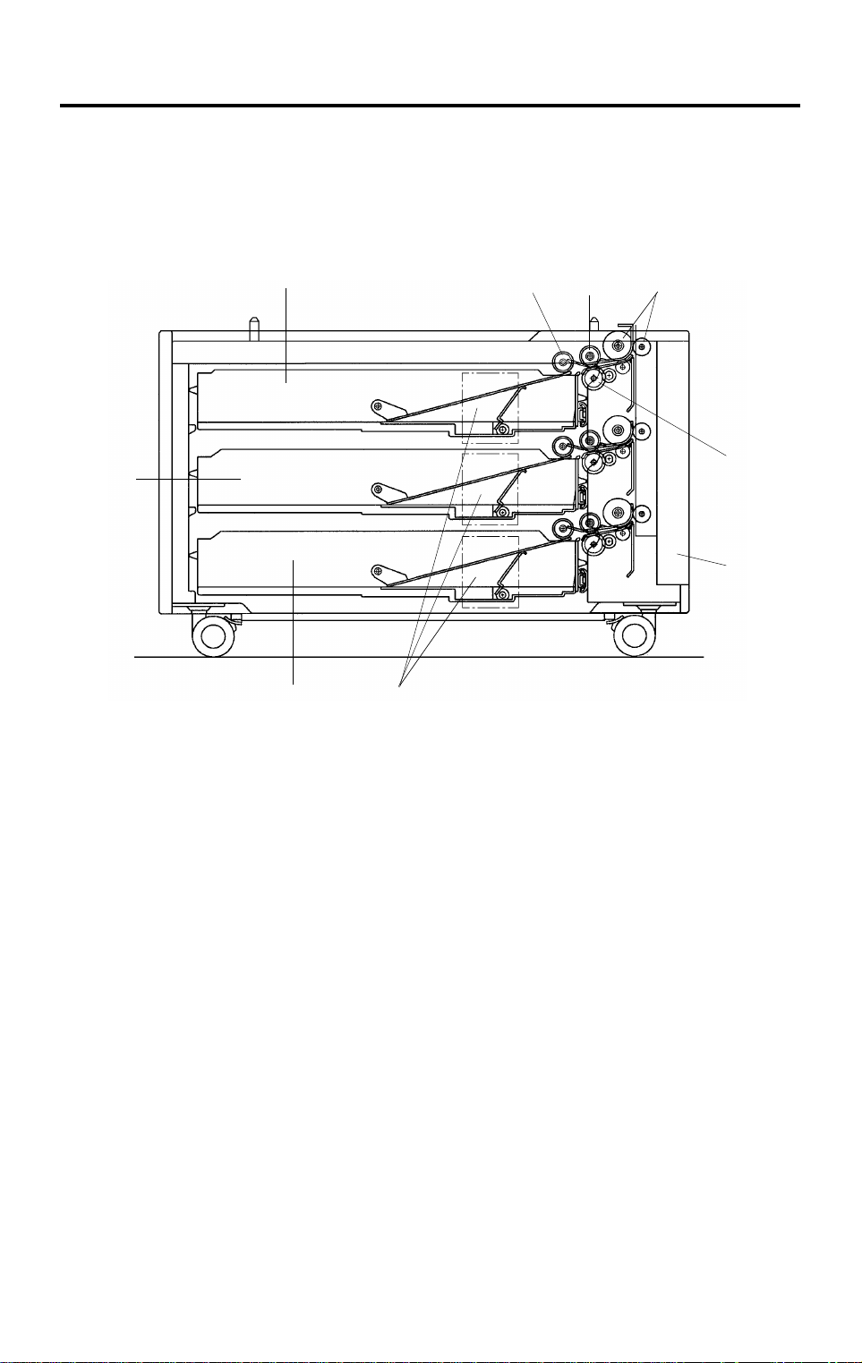
2. COMPONENT LAYOUT
2.1 MECHANICAL COMPONENT LAYOUT
1
9
8
7
2
3
4
5
6
1. Paper Tray 1
2. Pick-up Roller
3. Paper Feed Roller
4. Relay Rollers
5. Reverse Roller
A549V502.img
6. Lower Right Door
7. Paper Lift Motors
8. Paper Tray 3 (A549 model only)
9. Paper Tray 2
A549/A550-2
213
4
5
6
10 May 1996 COMPONENT LAYOUT
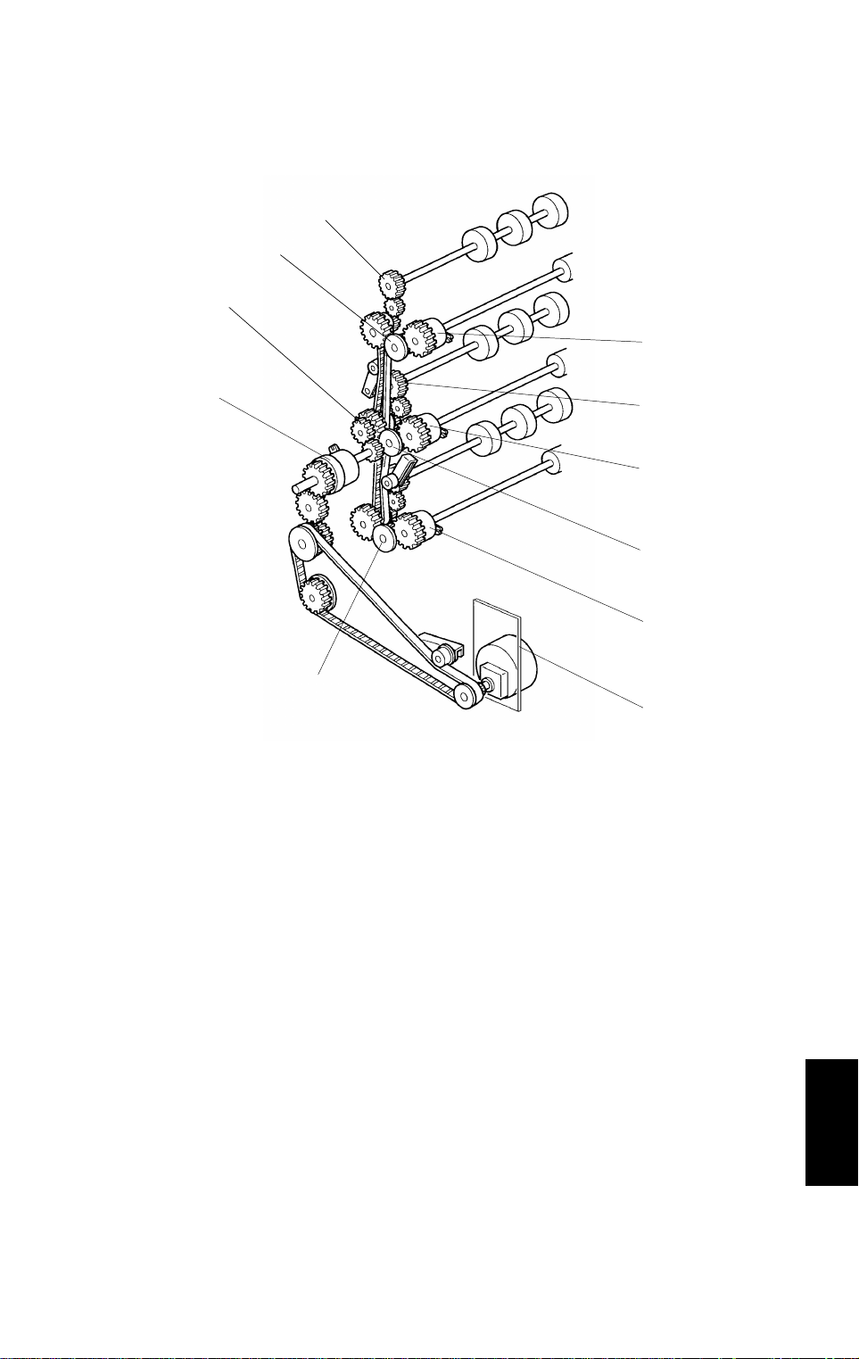
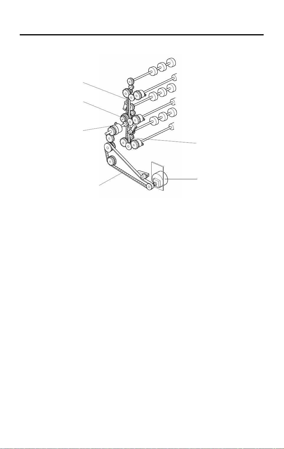
2.2 DRIVE LAYOUT
1
4
8
7
4
1. Vertical Transport Roller Gears
2. Paper Feed Clutch 1
3. Paper Feed Clutch 2
4. Separation Roller Gears
5. Paper Feed Clutch 3
A549V503.img
6. Main Motor
7. Relay Clutch
8. Timing Pulley
Options
A549/A550-3
COMPONENT LAYOUT 10 May 1996
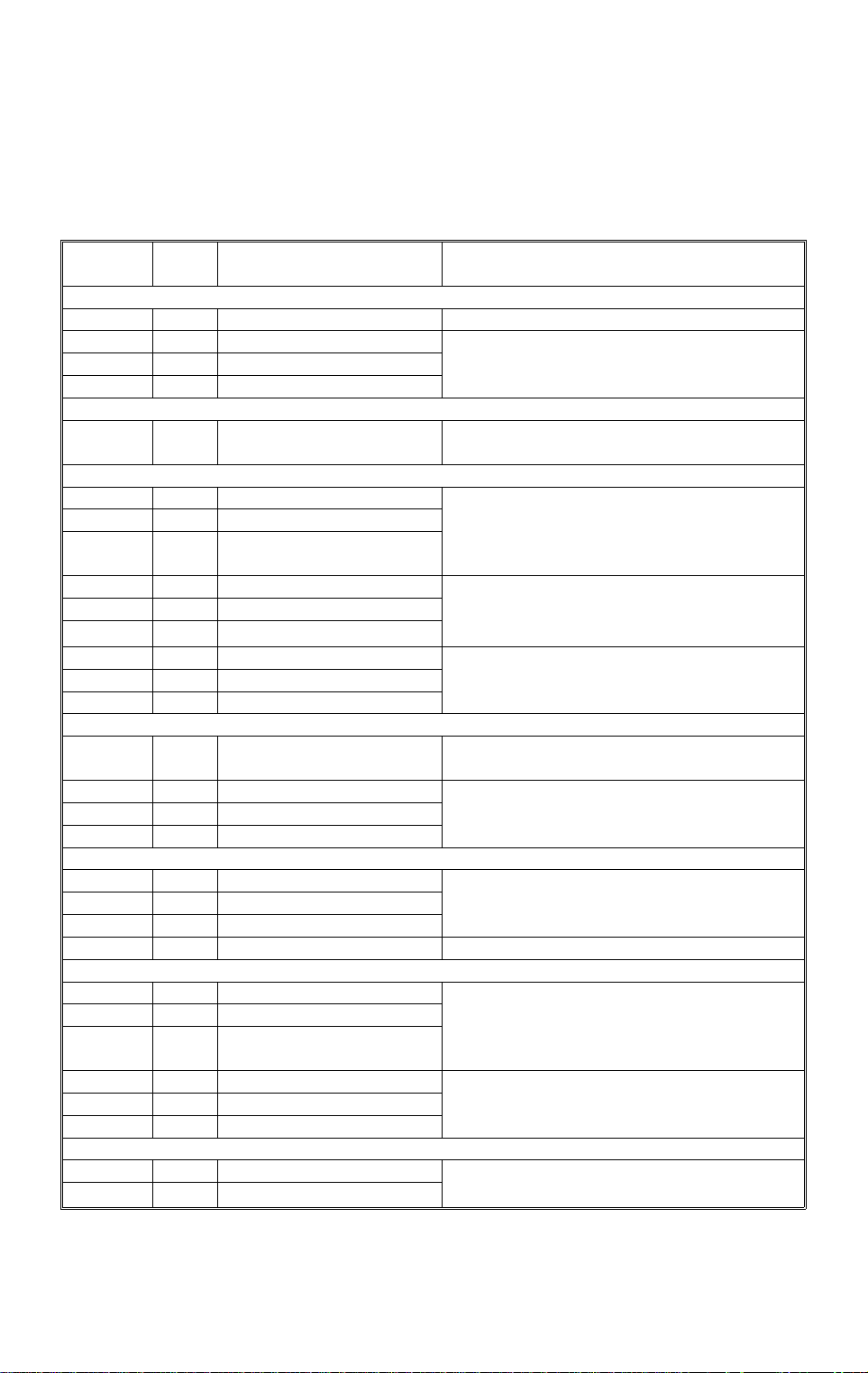
2.3 ELECTRICAL COMPONENT DESCRIPTI ON
Refer to the electrical compo nent layou t on the reverse side of the Point to
Point Diagram (on waterpro of paper).
Symbol
Motors
M1 5 Main Drives all the components of the paper tray
M2 2 Tray lift 1
M3 30 Tray lift 2
M4 29 Tray lift 3 (A549 only)
Circuit board
PCB1 1 Interface board
Sensors
S1 7 Tray upper limit 1
S2 18 Tray upper limit 2
S3 19
S4 25 Relay 1 Detects the leading edge of the paper as it
S5 23 Relay 2
S6 20 Relay 3
S7 28 Paper end 1
S8 24 Paper end 2
S9 21 Paper end 3 (A549 only)
Switches
SW1 22 Tray cover
SW2 3 Tray set 1
SW3 4 Tray set 2
SW4 6 Tray set 3 (A549 only)
Magnetic clutches
CL1 9 Paper feed 1
CL2 12 Paper feed 2
CL3 15 Paper feed 3 (A549 only)
CL4 11 Relay Drives the rollers in the paper trays
Solenoids
SOL1 8 Paper pick-up 1
SOL2 13 Paper pick-up 2
SOL3 16
SOL4 10 Separation 1
SOL5 14 Separation 2
SOL6 17 Separation 3
Heaters
H1 26 Tray (Option) Turns on when the main switch is off to
H2 27 Tray (Option)
Index
No.
Description Note
Tray upper limit 3 (A549
only)
Paper pick-up 3 (A549
only)
Raises the bottom plate in the paper tray
Controls the paper tray in response to
signals from the copier
Detects the top of the stack to stop the tray
lift motor
leaves the tray to control pick-up solenoid
and jam detection timing
Detects when the paper tray is empty
Detects whether the tray unit cover is open
and cuts the 24 Vdc power if it is
Detects whether the paper tray is in place
Starts feeding paper from the tray
Lifts/drops the pick-up roller
Lifts/drops the separation roller
keep the paper in the trays dry
A549/A550-4
10 May 1996 OVERVIEW
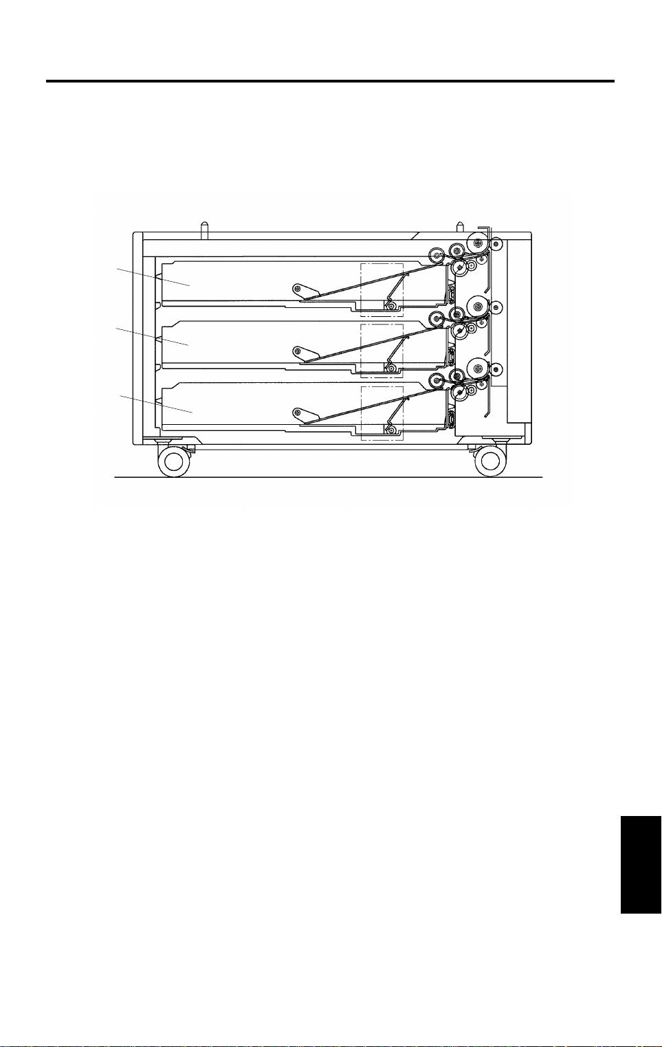
3. OVERVIEW
[A]
[A]
[A]
A549D502.img
There are two types of paper tray un it: the two-t ray an d three-tray types.
Each paper tray [A] is a drawer type th at can hold up to 500 she et s of pape r.
The paper feed mechan ism uses an FRR feed system. Th e fu nct ion of th e
system is exactly the same as for the main machine except that the re is no
paper size detection. The paper size for each paper tray is input at the
operation panel, eith er by th e user or by a technician.
All the electrical components of the pap er tra y are con tro lled by the copier
main board through the tray interface board .
Options
A549/A550-5
DRIVE MECHANISM 10 May 1996
4. DRIVE MECHANISM
[E]
[B]
[D]
[F]
[A]
[C]
A549D503.img
All the tray rollers are driven by the main motor [A] via timing belt s, clut che s
and a train of gears.
Drive is transmitted to the timing pulley [B] thro ugh the timin g belt [C] , rela y
clutch [D] and the gears.
Paper Feed Unit 1:
The drive from the timing pulley is transmitted to the unit throu gh the timing
belt [E].
Paper Feed Unit 2:
The drive from the timing pulley is directly transmitt ed to the unit.
Paper Feed Unit 3:
The drive from the timing pulley is transmitted to the unit throu gh the timing
belt [F].
The main motor and the relay clutch are energized at the same time that the
Start key is pressed.
The paper feed clutch is energize d 300 ms a ft er th e main moto r starts to
rotate. When th e pa pe r fee d clut ch fo r t he select ed paper tray is energized,
paper is fed from the paper tray to the main mach ine through the relay rollers.
A549/A550-6
 Loading...