

Page 1

PAPER TRAY UNIT
(Machine Code: A549/550)
Page 2

10 May 1996 SPECIFICATIONS
1. SPECIFICATIONS
Configuration : Two-tray table or three-tray ta ble
Copy Paper Size: Maximum A3/11" X 17"
Minimum B5/81/2" X 11"
Copy Paper Weight: 52 - 105 g/m2, 14 - 28 lb
Copy Paper Capacity: Approximately 500 sheets
Paper Feed Speed: 20 ~ 40 copies/minute (A4 / 81/2"X11" sideways)
Power Source: DC 24V, 5V and AC 120V, 220~240V from the
main machine
Power Consumption: Maximum 110.5 W
Average 50 W
Dimensions: 620 mm/24.4" (width) X 632 mm /24.9" (depth) X
390 mm/15.4" (height)
Weight: Less than 36 kg/79.4 lb (Two-tray type)
Less than 38 kg/83.8 lb (Three-tray type)
A549/A550-1
Options
Page 3
COMPONENT LAYOUT 10 May 1996
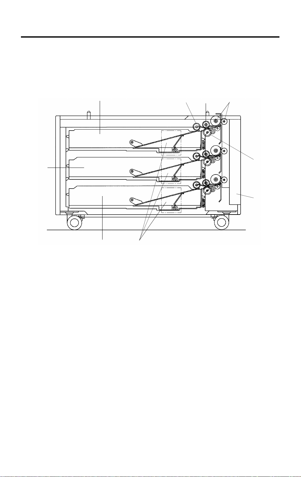
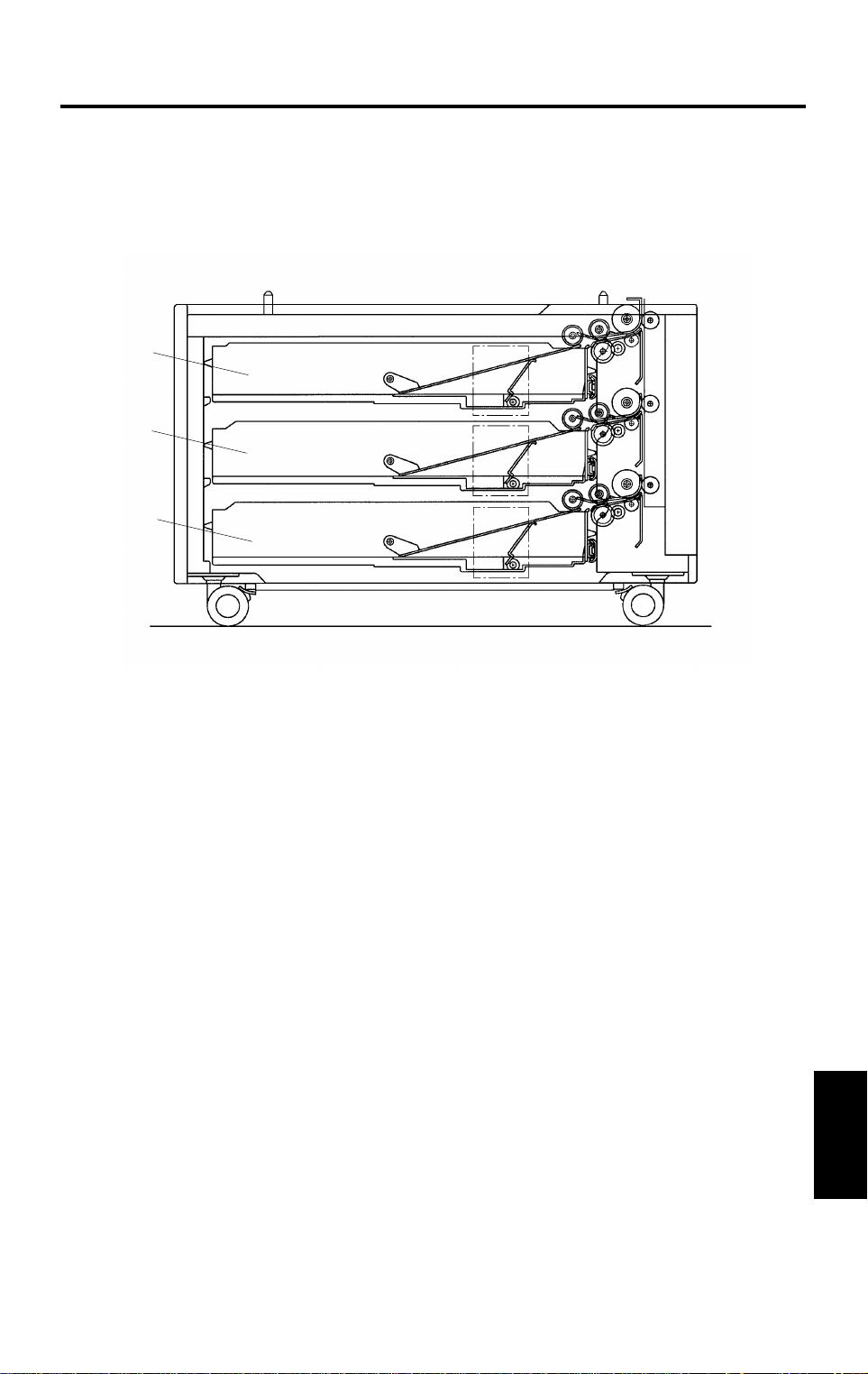
2. COMPONENT LAYOUT
2.1 MECHANICAL COMPONENT LAYOUT
1
9
8
7
2
3
4
5
6
1. Paper Tray 1
2. Pick-up Roller
3. Paper Feed Roller
4. Relay Rollers
5. Reverse Roller
A549V502.img
6. Lower Right Door
7. Paper Lift Motors
8. Paper Tray 3 (A549 model only)
9. Paper Tray 2
A549/A550-2
Page 4
213
4
5
6
10 May 1996 COMPONENT LAYOUT
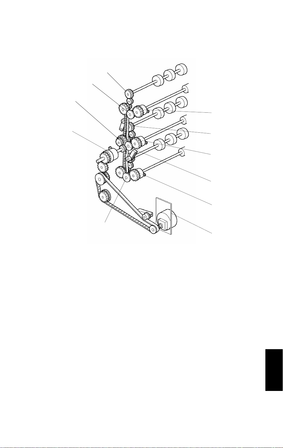
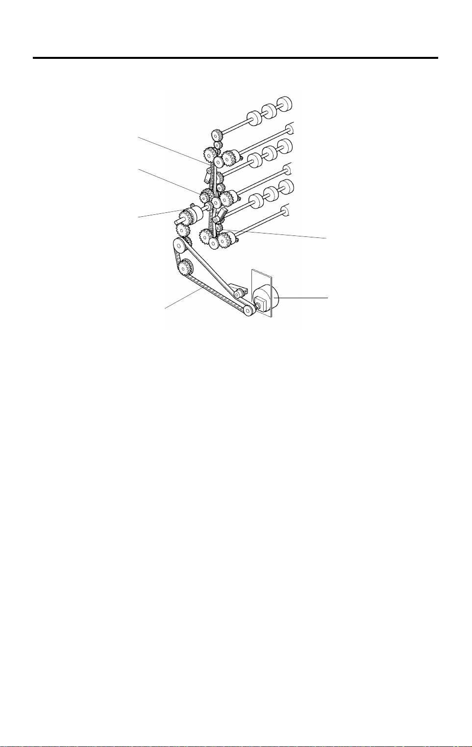
2.2 DRIVE LAYOUT
1
4
8
7
4
1. Vertical Transport Roller Gears
2. Paper Feed Clutch 1
3. Paper Feed Clutch 2
4. Separation Roller Gears
5. Paper Feed Clutch 3
A549V503.img
6. Main Motor
7. Relay Clutch
8. Timing Pulley
Options
A549/A550-3
Page 5

COMPONENT LAYOUT 10 May 1996
2.3 ELECTRICAL COMPONENT DESCRIPTI ON
Refer to the electrical compo nent layou t on the reverse side of the Point to
Point Diagram (on waterpro of paper).
Symbol
Motors
M1 5 Main Drives all the components of the paper tray
M2 2 Tray lift 1
M3 30 Tray lift 2
M4 29 Tray lift 3 (A549 only)
Circuit board
PCB1 1 Interface board
Sensors
S1 7 Tray upper limit 1
S2 18 Tray upper limit 2
S3 19
S4 25 Relay 1 Detects the leading edge of the paper as it
S5 23 Relay 2
S6 20 Relay 3
S7 28 Paper end 1
S8 24 Paper end 2
S9 21 Paper end 3 (A549 only)
Switches
SW1 22 Tray cover
SW2 3 Tray set 1
SW3 4 Tray set 2
SW4 6 Tray set 3 (A549 only)
Magnetic clutches
CL1 9 Paper feed 1
CL2 12 Paper feed 2
CL3 15 Paper feed 3 (A549 only)
CL4 11 Relay Drives the rollers in the paper trays
Solenoids
SOL1 8 Paper pick-up 1
SOL2 13 Paper pick-up 2
SOL3 16
SOL4 10 Separation 1
SOL5 14 Separation 2
SOL6 17 Separation 3
Heaters
H1 26 Tray (Option) Turns on when the main switch is off to
H2 27 Tray (Option)
Index
No.
Description Note
Tray upper limit 3 (A549
only)
Paper pick-up 3 (A549
only)
Raises the bottom plate in the paper tray
Controls the paper tray in response to
signals from the copier
Detects the top of the stack to stop the tray
lift motor
leaves the tray to control pick-up solenoid
and jam detection timing
Detects when the paper tray is empty
Detects whether the tray unit cover is open
and cuts the 24 Vdc power if it is
Detects whether the paper tray is in place
Starts feeding paper from the tray
Lifts/drops the pick-up roller
Lifts/drops the separation roller
keep the paper in the trays dry
A549/A550-4
Page 6
10 May 1996 OVERVIEW
3. OVERVIEW
[A]
[A]
[A]
A549D502.img
There are two types of paper tray un it: the two-t ray an d three-tray types.
Each paper tray [A] is a drawer type th at can hold up to 500 she et s of pape r.
The paper feed mechan ism uses an FRR feed system. Th e fu nct ion of th e
system is exactly the same as for the main machine except that the re is no
paper size detection. The paper size for each paper tray is input at the
operation panel, eith er by th e user or by a technician.
All the electrical components of the pap er tra y are con tro lled by the copier
main board through the tray interface board .
Options
A549/A550-5
Page 7
DRIVE MECHANISM 10 May 1996
4. DRIVE MECHANISM
[E]
[B]
[D]
[F]
[A]
[C]
A549D503.img
All the tray rollers are driven by the main motor [A] via timing belt s, clut che s
and a train of gears.
Drive is transmitted to the timing pulley [B] thro ugh the timin g belt [C] , rela y
clutch [D] and the gears.
Paper Feed Unit 1:
The drive from the timing pulley is transmitted to the unit throu gh the timing
belt [E].
Paper Feed Unit 2:
The drive from the timing pulley is directly transmitt ed to the unit.
Paper Feed Unit 3:
The drive from the timing pulley is transmitted to the unit throu gh the timing
belt [F].
The main motor and the relay clutch are energized at the same time that the
Start key is pressed.
The paper feed clutch is energize d 300 ms a ft er th e main moto r starts to
rotate. When th e pa pe r fee d clut ch fo r t he select ed paper tray is energized,
paper is fed from the paper tray to the main mach ine through the relay rollers.
A549/A550-6
Page 8

10 May 1996 PAPER FEED AND MISFEED DETECTION TIMING
5. PAPER FEED AND MISFEED DETECTION
TIMING
A4 Sideways, Lower Paper Feed Station, Line spe ed 200 mm/s
A549D504.wmf
J1 and J2: Checks whether the sensor is activated within 500 ms after
the designated time for these sensors.
Options
A549/A550-7
Page 9

SERVICE TABLES 10 May 1996
6. SERVICE TABLES
6.1 DIP SWITCHES
DIP SW 101 (Free Run Mode)
1234567 Function
Off------Speed in the free run mode: 200 mm/s
On------Speed in the free run mode: 150 mm/s
-OnOff----Bank type : 500 sheet type
-OffOn----Bank type : 250 sheet type
---OffOn--
- - - On Off - -
---OnOn--
-----OnOffFree Run Mode 2
-----OnOnFree Run Mode 1
-----OffOffNormal Operation
Normal Operation / Free Run Mode 1*: One-tray type
Free Run Mode 2*: Paper feed tray 1 only
Normal Operation / Free Run Mode 1*: Two-tray type
Free Run Mode 2*: Paper feed tray 2 only
Normal Operation / Free Run Mode 1*: Three-tray type
Free Run Mode 2*: Paper feed tray 3 only
Do not touch dip switches 1 to 5. Switch 8 is not used.
How to do a free run
1. Select either mode 1 or mode 2 with dip switches 6 and 7.
2. Turn off the power, disconnect th e optica l cable, and turn on the power.
3. Press SW101 on the PCB to sta rt th e free run.
4. When you wish to stop the free ru n, press SW1 02 on the PCB and return
the dip switches to their default set tings.
Free Run Mode 1
The paper feed operation performs up to 20 times for each pa per fee d statio n.
(10 s) (10 s) (10 s)
1st feed station 2nd feed station 3rd feed station
Repeat Two paper feed tray type
Repeat Three paper feed tray type
Free Run Mode 2
The paper feed operation run s for all pa per f eed sta tio ns at the same time .
A549/A550-8
Page 10

10 May 1996 SERVICE TABLES
6.2 TEST POINTS
NUMBER FUNCTION
TP101 + 5V
TP102 + 24V
TP103 GND
TP104 TXD (Transmit signal)
TP105 RXD (Receive signal)
TP106 GND
A549/A550-9
Options
Page 11

REPLACEMENT AND ADJUSTMENT 10 May 1996
7. REPLACEMENT AND ADJUSTMENT
7.1 EXTERIOR COVER REMO VAL
[E]
[A]
[D]
[B]
Rear Cover [A]: (2 screws)
Front Lower Cover [B]: [Two-tray type only]
1. Slide out the cassettes.
2. Remove the front lower cover (2 screws).
Right Front Cover [C]:
1. Remove the front lower cove r [ B] .
2. Remove the right front cover (2 screws).
Right Rear Cover [D]:
1. Remove the rear cover [A ].
2. Remove the right rear cover (2 screws).
Left Cover [E]:
1. Remove the rear cover [A ].
2. Remove the front lower cove r [ B] .
3. Remove the left cover (4 screws).
[C]
A549R507.wmf
A549/A550-10
Page 12

[B]
[D]
10 May 1996 REPLACEMENT AND ADJUSTMENT
7.2 PAPER FEED CLUTCH REPLACEMENT
[C]
A549R508.img
1. Remove the rear cover (see Exte rior Cover Removal).
2. Remove the timing belt [A].
3. Remove the drive unit [B] (2 screws, 2 con nectors).
4. Remove the separatio n rolle r gear [ C].
5. Remove the paper feed clutch [D] (1 conn ect or).
NOTE: When rein stalling the clutch, make sure that the clutch stop per
groove engages the sto pp er bracket.
[A]
Options
A549/A550-11
Page 13

REPLACEMENT AND ADJUSTMENT 10 May 1996
7.3 PAPER FEED UNIT REPLACEME NT
[A]
[B]
[C]
[D]
A549R509.wmf
1. Remove the paper feed clutch (see Paper Feed Clutch Replacement).
2. Remove the paper feed roller ge ar [A ].
3. Pull out all the trays.
4. Two-tray type only: Remove the front lower cove r (se e Ext erio r Cover
Removal).
5. Remove the front right cover [B] (2 screws).
6. Remove the paper feed unit [C] (2 screws fo r each unit ).
NOTE: When remo ving the paper feed unit, do the following .
• When removing the paper feed roller ge ar, remove the rubb er
foot [D].
• Remove the joint bracket .
After reinstalling th e pa per t ray, perf orm th e side -to side-re gistration
adjustment (see Removal and Adjustment in the manual for the
copier).
A549/A550-12
Page 14

[B]
10 May 1996 REPLACEMENT AND ADJUSTMENT
7.4 FEED ROLLER, PICK-UP ROLLE R, AND REVERSE
ROLLER REPLACEMENT
[C]
[D]
[A]
A549R510.wmf
1. Remove the paper feed tray [A ] (4 screws).
2. Remove the feed roller [B], pick-up rolle r [C], and reverse roller [D] (1 clip
each).
NOTE: Afte r re inst allin g th e pa per t ray, perf orm th e side -to -side registration
adjustment (see Removal and Adjustment in the manual for the
copier).
Options
A549/A550-13
Page 15

REPLACEMENT AND ADJUSTMENT 10 May 1996
7.5 RELAY SENSOR REPLACEMENT
[A]
[C]
[E]
A549R511.wmf
[B]
A549R513.img
1. Remove the rear cover (see Exterior Cover Removal).
2. Remove the right rear cover (see Exterior Cover Removal).
3. Remove the drive unit [A] (2 screws, 2 connectors).
4. Remove the vertical transpo rt un it [B ] (2 screws).
5. Remove the vertical transpo rt gu ide [C] (4 screws).
[D]
A549R512.wmf
6. Remove the sponge [D].
7. Remove the relay sensors [E ] (1 con ne cto r e ach ).
A549/A550-14
Page 16

PAPER TRAY UNIT (A549/A550) INSTALLATION 10 May 1996
4. PAPER TRAY UNIT (A549/A550)
INSTALLATION
4.1 ACCESSORY CHECK
Check the quantity and cond itio n of the accessories in the box with the
following list:
1. Right Support Bracket .....................................................................1
2. Left Support Bracket........................................................................1
3. Joint Bracket....................................................................................1
4. Shoulder Screw ..............................................................................1
5. Screw - M4 x 8............... .......... .. .. .......... .. .......... .. .. .......... .. .......... .. ..4
6. New Equipment Condition Report...................................................1
7. Installation Procedure .....................................................................1
3-38
Page 17

[A]
10 May 1996 PAPER TRAY UNIT (A549/A550) INSTALLATION
4.2 INSTALLATION PROCEDURE
A549I509.wmf A549I510.wmf
Installation
A549I511.wmf
CAUTION
I
Unplug the copier power cord before starti ng the follow ing proc edur e.
NOTE: Keep the shipping retaine rs aft er inst alling the machine. They will be
reused if the machine is transported to another location. Proper
reinstallation of the shipping retainers is required in order t o avoid
any transport damage.
1. Remove the strips of tape.
2. Remove the bottom plate stopper [A].
3-39
Page 18

PAPER TRAY UNIT (A549/A550) INSTALLATION 10 May 1996
[B]
[F]
[I]
[D]
[H]
[D]
[J]
A549I513.wmf
A549I512.wmf
[C]
For Copiers with an LCT: Do not lift the
copier by holding the LCT unit.
[G]
[E]
[K]
A549I514.wmf
3. Set the copier [B] on th e pa pe r tray un it [C] . Alig n the 2 pins [D] on the
paper tray unit with the holes in the base plate of the copier.
4. Open the lower door [ E] . Also , op en eith er th e LCT [F] or the upp er righ t
door [F], (depending on the type of copier).
5. Secure the copier to the paper tray unit with the joint bra cket [G] .
6. Connect the cable [H] an d op tic fib er [I].
7. Attach the support bracke ts [J] to the bottom of the pap er tra y unit as
shown (4 screws).
CAUTION
I
If you do not attach the support bracket, the machine may fal l
forwards when the paper tray s are pull ed open.
8. Pull out the paper tray an d loa d pa pe r into it . (The pape r size and
direction for each tray sho uld be designated by a customer. )
Position the side and rear fences properly.
9. Turn on the main switch.
10. Enter the prope r pap er size for each paper tray by following the
procedure in the copier’s manual.
11. Attach the appropriate tray decals [K] which are included in the accessory
box with the main copier.
12. Check the machine ’s ope rat ion and copy qu alit y.
3-40
Page 19

10 May 1996 PAPER TRAY UNIT (A549/A550) INSTALLATION
4.3TRAY HEATER (OPTION)
[E]
[F]
[B]
[E]
[F]
[C]
- Two-tray type -
A549I516.wmf
[A]
[H]
- Three-tray type -
[D]
A549I515.wmf
1. Remove the rear cover [A].
[A]
[G]
A549I517.wmf
2. Two-tray type: Remove the second paper tray [B] (4 screws) and the
lower front cover [C] (2 screws).
Installation
Three-tray type: Remove the second and third paper feed trays [D] (4
screws each).
3. Install the tray heaters [E] (2 screws each).
4. Install the clamper [F] and clamp the heater harnesses.
5. Install the heater bracket [G] (2 screws).
6. Connect the heater harnesses.
7. Install the clamper [H] and clamp the heater harnesses.
NOTE:After replacing the paper tray, perform the side-to-side registration
adjustment (see Replacement and Adjustment in the copier manual).
3-41
Page 20

Page 21

PAPER TRAY UNIT (A549/A550) ELECTRICAL COMPO NENT
4
5
17
18
LAYOUT
29
28
27
30
26
12
3
6
7
8
9
10
11
12
13
14
15
16
25
24
23
14
202122
19
A166S502.wmf
Page 22

Index No. Description P to P
Location
1 Interface Board (PCB1) F8
2 Tray Lift Motor 1 (M2) E2
3 Tray Set Switch 1 (SW2) H2
4 Tray Set Switch 2 (SW3) H2
5 Main Motor (M1) F2
6 Tray Set Switch 3 (A549 only) (SW4) I2
7 Tray Upper Limit Sensor 1 (S1) E16
8 Paper Pick-up Solenoid 1 (SOL1) D16
9 Paper Feed Clutch 1 (CL1) K16
10 Separation Solenoid 1 (SOL4) E16
11 Relay Clutch (CL4) J16
12 Paper Feed Clutch 2 (CL2) K16
13 Paper Pick-up Solenoid 2 (SOL2) F16
14 Separation Solenoid 2 (SOL5) G16
15 Paper Feed Clutch 3 (A549 only) (CL3) L16
16 Paper Pick-up Solenoid 3
(A549 only) (SOL3)
17 Separation Solenoid 3 (A549 only) (SOL6) J16
18 Tray upper Limit Sensor 2 (S2) G16
19 Tray upper Limit Sensor 3
(A549 only) (S3)
20 Relay Sensor 3 (A549 only) (S6) C16
21 Paper End Sensor 3 (A549 only) (S9) H16
22 Tray Cover Switch (SW1) A16
23 Relay Sensor 2 (S5) B16
24 Paper End Sensor 2 (S8) F16
25 Relay Sensor 1 (S4) B16
26 Tray Heater (Option) (H1) B6
27 Tray Heater (Option) (H2) C6
28 Paper End Sensor 1 (S7) C16
29 Tray Lift Motor 3 (A549 only) (M4) F2
30 Tray Lift Motor 2 (M3) E2
I16
I16
15
 Loading...