

Page 1

20 December 1991 SPECIFICATIONS
1. SPECIFICATIONS
Copy Paper Size: Maximum A3 or 11" x 17"
Minimum B5R or 51/2" x 81/2"
Copy Paper Weight: Black or single color copies: 52 to 104g
14 to 281b
Full color copies: 64 to 104g
17 to 281b
Paper Feed System: Feed and reverse roller (FRR)
Power Source: 100 V, 50/60 Hz, 0.6 A (From Copier)
Dimensions (W x H x
D):
Weight: 55 kg (1211b)
835 mm x 425 mm x 640 mm
(32.9") (16.7") (26.7")
1
Page 2
PAPER SIZE AND END DETECTION 20 December 1991
2. PAPER SIZE AND END DETECTION
[E]
[A]
[B]
[F]
[D]
[C]
Paper size is detected by an array of five ph ot ointerrupters [A] in the cassette
entrance. The paper size sen sors are actuated by a plate on the front of the
cassette. Each paper size ha s it s own un iqu e combination of notche s in the
actuator plate [B]. The CPU rea ds which photointerrupters have been
de-actuated (0 V to 5 V) by the actuator pla te to dete rmine which pa per size
has been inserted.
When a cassette runs out of pape r, the paper end feeler [C] drop s thro ug h a
slot [D] in the cassette bottom plate. The paper end actuator [E], which is on
the same shaft as the pa per e nd fee ler, pivot s in to the det ect or
(photointerrup te r) [ F]. The de tector then provides a HIGH sign al to the CPU
informing it that the ca sset te is empty.
The Add Paper indicator th en turns on, the Start key turns red, an d th e
machines stops after th e cop y is fin ishe d.
2
Page 3

20 December 1991 PAPER SIZE AND END DETECTION
Actuator Plate Combination Table
Paper Size
A3
B4
A4 sideways
A4 lengthwise
B5 sideways
B5 lengthwise
A5 sideways
A5 lengthwise
B6 sideways
B6 lengthwise
Return Post Card
Post Card
11" x 17"
11" x 81/2"
11" x 15"
10" x 14"
81/2 " x 14"
81/2" x 13"
81/2" x 11"
81/2" x 51/2"
81/2" x 13"(14")
8" x 13" (14")
8" x 101/2"
8" x 10"
51/2" x 81/2"
No Cassette
Sensor No. Operation Panel Indicat ion
1 2 3 4 5 220 V 115 V
1 0 0 0 0
1 1 0 0 0
0 0 1 0 0
1 0 1 0 0
0 1 1 0 0
1 1 1 0 0
0 0 0 1 0
1 0 0 1 0
0 1 0 1 0
1 1 0 1 0
0 0 1 1 0
0 0 1 1 0
0 0 0 0 1
1 0 0 0 1
0 1 0 0 1
1 1 0 0 1
0 0 1 0 1
1 0 1 0 1
0 1 1 0 1
1 1 1 0 1
0 0 0 1 1
1 0 0 1 1
0 1 0 1 1
1 1 0 1 1
0 0 1 1 1
1 1 1 1 1
A3
B4
A4
A4R
u32
*
u32
u32
u32
u32
u32
u32
*
*
*
*
*
F4
*
u32
*
F
*
*
*
*
*
*
*
*
*
*
*
*
*
*
*
*
11" x 17"
11" x 81/2"
11" x 15"
*
81/2" x 14"
*
81/2" x 11" R
81/2" x 51/2"
*
*
*
*
51/2" x 81/2"
*
1: Not interrupte d (Lo w)
0: Interrupted (High)
3
Page 4

PAPER SIZE AND END DETECTION 20 December 1991
ACCESSORY CHECK
Check the quantity and condition of the accessories in the box acco rding to
the following list:
1. Installation Procedure......................................................................1
2. Idle Gear ..........................................................................................1
3. Harness Bracket ........ .......... .. .......... .. .................... .. .......... .. ...........1
4. Grounding Screw.. .. ............ .. .. ............ .. .. ............ .. ............ .. .. ...........4
5. Screw ..............................................................................................1
6. Washer.............................................................................................1
7. New Equipment Condit ion Report (17 and 27 machines)...............1
8. Envelop for NECR (17 machine only)..............................................1
9. Multilingual Decal (16, 25 , 26 and 27 machines).............. ............ ...1
4
Page 5

[C]
20 December 1991 PAPER SIZE AND END DETECTION
[A]
[A]
[A]
[A]
[B]
INSTALLATION PROCEDURE
NOTE: Turn off the main switch and remove the plu g.
1. Remove all external strips of tape [A] .
2. Open the right and left doors, and remove the strips of tape [B] and the
screw [C].
5
Page 6

PAPER SIZE AND END DETECTION 20 December 1991
[A]
[E]
[D]
[B]
[D]
[C]
[G]
[F]
3. Place the copier on the paper feed unit align ing the positioning pins [A] of
the copier with the positioning hole s [B] of the pape r fee d unit.
NOTE: a) Take care that the pape r ban k harn ess do es no t ge t caught
between the copier and the table durin g positio ning.
b) Take care not to damage th e en tra nce guide plate [C].
4. Secure the copier to the pape r fee d unit as sho wn (4 grounding screws
[D], 1 washer [E].
5. Place the four leveling shoes [F] under the leveling feet [G] and screw the
leveling feet up or down to level the machine.
NOTE: Set a carpenter’s level on th e exposure glass.
1. Font to back Within 5 mm (0.2") of level
2. Right to left Within 5 mm (0.2") of level
6
Page 7

20 December 1991 PAPER SIZE AND END DETECTION
[A]
[D]
[B]
[C]
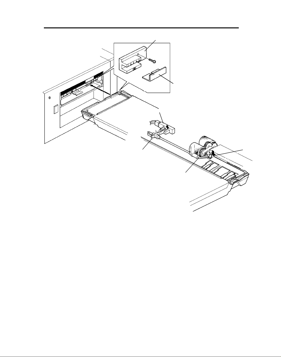
6. Remove the copier rear cover [A] (3 screws).
7. Open the power supply section [B ] (1 gro un din g screw).
8. Remove the securing bracke t [C] (1 scre w) and the cover bra cket [D] (1
screw).
7
Page 8

PAPER SIZE AND END DETECTION 20 December 1991
[A]
[B]
9. Pull the copier left lift hand le and install the idle gear [A] (1 screw) as
shown.
10. Fix the idle gear so that it contacts the black gear [B].
8
Page 9

[B]
20 December 1991 PAPER SIZE AND END DETECTION
[C]
[A]
[D]
CAUTION: When closing the power supply section [A], use the
grounding screw [B] (#6) for proper grounding.
11. Disconnect the conne cto r [ C].
12. Connect the paper feed unit harne ss to th e copier ha rne ss a s shown .
13. Install the harness bracket [D] using the screw removed in #8 as shown.
14. Reinstall the power supply section (1 groun din g screw).
15. Reinstall the copier rear cover.
9
Page 10

PAPER SIZE AND END DETECTION 20 December 1991
[A]
[E]
[D]
[B]
17. Plug in the copier and turn on the main switch. After warming up, enter
the SP mode as follows: while pressing the SP mode [A]and "8" keys,
press the enter key.
18. Enter the 3rd paper feed operation mode as follows:
19. Exit SP mode by pressing the Clear Mod es key.
20. To adjust the horizontal registration of the 3rd paper feed section :
72
1) Compare the copy from the 1st paper f eed sect ion with that from the
3rd paper feed section.
2) Remove the left cover [B] of th e 3rd paper feed unit (2 screws).
3) Loosen the 4 screws [C] of the paper feed unit [D].
4) Move the paper feed unit and actu ator [E] the same amount tha t it was
adjusted.
5) Reassemble all parts.
R/#
1
[C]
R/#
10
 Loading...