

Ricoh PJ X5770, PJ WX5770, PJ WU5760, PJ KU600, PJ KU650 Field Service Manual
...
Model Shaula-PJ1
RICOH PJ
X5770/WX5770/WU5760/
X600/KW600/KU600/KU650
Machine Codes:
Y0BG/Y0BH/Y0BJ/Y0BM/
Y0BN/Y0BP/Y236
Field Service Manual
May, 2017


Important Safety Notices
Important Safety Notices
Prevention of physical injury
1. Before disassembling or assembling parts of the main machine and peripherals, make sure that the
power cord of the main machine is unplugged.
2. The wall outlet should be near the machine and easily accessible.
3. If any adjustment or operation check has to be made with exterior covers off or open while the
main switch is turned on, keep hands away from electrified or mechanically driven components.
• To prevent a fire or explosion, keep the machine away from flammable liquids, gases, and
aerosols.
Health safety conditions
• This machine, which uses a high voltage power source, can generate ozone gas. High ozone
density is harmful to human health. Therefore, the machine must be installed in a well-ventilated
room.
Observance of electrical safety standards
• This machine and its peripherals must be serviced by a customer service representative who has
completed the training course on those models.
Safety and Ecological Notes for Disposal
• Dispose of replaced parts in accordance with local regulations.
1
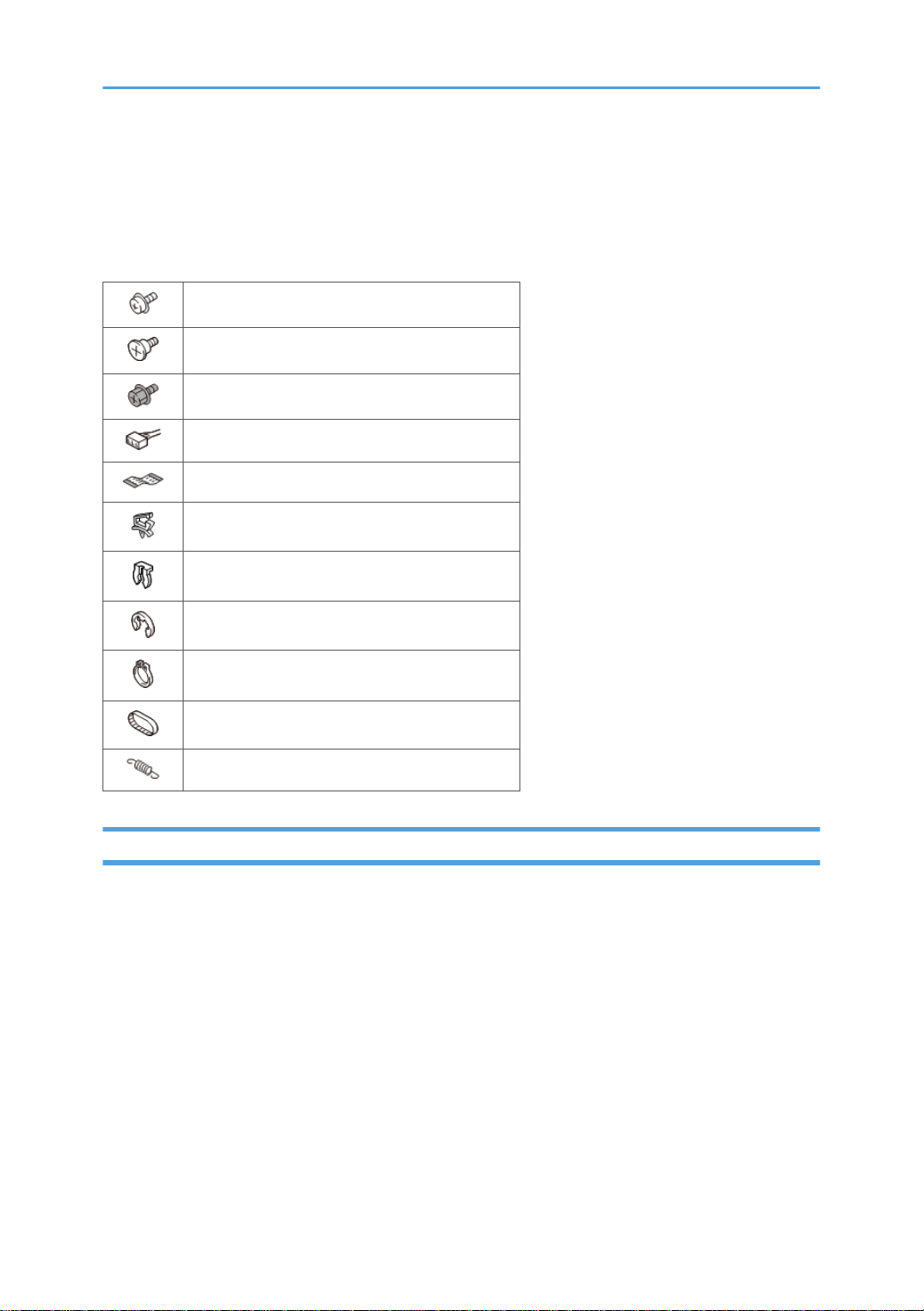
Symbols, Abbreviations and Trademarks
This manual uses several symbols and abbreviations. The meaning of those symbols and abbreviations
are as follows:
Screw
Shoulder screw
Black screw (TCRU)
Connector
FFC (Flat Film Connector)
Harness clamp
Clip
E-ring
C-ring
Timing belt
Spring
Trademarks
• DLP is a trademark or registered trademark of Texas Instruments.
• Microsoft, Windows, Internet Explorer and PowerPoint are either a registered trademark or
trademark of Microsoft Corporation in the United States and/or other countries.
• HDMI, the HDMI Logo and High-Definition Multimedia Interface are trademarks or registered
trademarks of HDMI Licensing LLC.
• DisplayPort, DisplayPort Compliance Logo are registered trademarks of Video Electronics
Standards Association.
• MHL, Mobile High-Definition Link, and MHL Logo are trademarks or registered trademarks of
MHL, LLC.
• Kensington is a trademark or registered trademark of ACCO Brands.
• Blu-ray is a trademark of Blu-ray Association.
2

• Other product and company names mentioned in this manual may be the trademarks or registered
trademarks of their respective holders.
3

TABLE OF CONTENTS
Important Safety Notices................................................................................................................................... 1
Important Safety Notices............................................................................................................................... 1
Prevention of physical injury................................................................................................................. 1
Health safety conditions........................................................................................................................1
Observance of electrical safety standards.......................................................................................... 1
Safety and Ecological Notes for Disposal................................................................................................... 1
Symbols, Abbreviations and Trademarks.........................................................................................................2
Trademarks..................................................................................................................................................... 2
1. Introduction
Overview/Specifications...................................................................................................................................9
Before Handling the Unit................................................................................................................................. 10
Installation.................................................................................................................................................... 10
Precautions................................................................................................................................................... 10
Do..................................................................................................................................................................13
Do not........................................................................................................................................................... 13
2. Replacement
Special Tools.................................................................................................................................................... 15
Parts List.............................................................................................................................................................16
Service Parts List........................................................................................................................................... 16
Replaceable Part Hierarchy............................................................................................................................ 19
Equipment Needed..........................................................................................................................................22
Part Replacement..............................................................................................................................................23
Lens Cap.......................................................................................................................................................23
Filter...............................................................................................................................................................23
Adjustable Feet (Front x1, Rear x2)........................................................................................................... 24
Lamp Cover, Lamp Module........................................................................................................................ 24
Top Cover (Including Mini HDMI Cable and Keypad Rubber).............................................................. 26
Mini HDMI Cable............................................................................................................................... 28
Keypad Rubber................................................................................................................................... 28
Left Fans (1 and 2).......................................................................................................................................29
Color Wheel Module (Including Photo Sensor and Color Wheel).........................................................30
Photo Sensor........................................................................................................................................31
Color Wheel........................................................................................................................................32
4

Front Cover (Including IR Sensor and IR Sensor Cover)...........................................................................32
IR Sensor and IR Sensor Cover.......................................................................................................... 34
Main Board (Including HDBaseT Board (WUXGA model only) and Sub Board).................................34
HDBaseT Board (Only for WUXGA model).....................................................................................36
Sub Board............................................................................................................................................37
Connector List...................................................................................................................................... 37
Shielding Bracket with Rear Cover and LVPS............................................................................................40
Right Fan ......................................................................................................................................................43
Speaker (Front) and Speaker Rubber........................................................................................................ 44
Speaker (Rear) and Speaker Rubber.........................................................................................................46
Lamp Housing.............................................................................................................................................. 46
Lamp Cable..................................................................................................................................................47
Optical System Unit (Including Focus Ring, Zoom Lever, Lens Shift Dial, Lens)..................................... 48
Focus Ring, Spacer, Zoom Lever, Lens Shift Dial, Lens....................................................................50
Blower Unit (Including Thermistor and Interlock Switch).......................................................................... 51
Thermistor and Interlock Switch......................................................................................................... 53
PSU................................................................................................................................................................53
Details of Each Connector on the PSU.............................................................................................. 55
AC Inlet.........................................................................................................................................................56
Bottom Shielding Plate.................................................................................................................................58
Bottom Cover............................................................................................................................................... 59
3. Troubleshooting
LED Display.......................................................................................................................................................61
Main Procedures.............................................................................................................................................. 62
4. Adjustment
Required Action after Replacing Parts............................................................................................................65
Test Equipment and Conditions.......................................................................................................................67
Test Equipment Needed.............................................................................................................................. 67
Recommended Test Condition.................................................................................................................... 67
Service Mode................................................................................................................................................... 68
How to Enter the Service Mode..................................................................................................................68
Service Mode Settings.................................................................................................................................70
Calibration........................................................................................................................................................74
5

Waveform Download and Fan Calibration...............................................................................................74
PC Calibration..............................................................................................................................................75
Calibration Procedure.........................................................................................................................75
Pattern Check.......................................................................................................................................76
Re-write Lamp Hours Usage ...........................................................................................................................78
Color Wheel Index.......................................................................................................................................... 81
Rod Adjustment.................................................................................................................................................83
Test Inspection Procedure................................................................................................................................84
Check Points................................................................................................................................................. 84
OSD Reset.................................................................................................................................................... 84
Method 1.............................................................................................................................................84
Method 2.............................................................................................................................................85
5. Firmware Update
System Firmware Update.................................................................................................................................87
Equipment Needed......................................................................................................................................87
Preparation...................................................................................................................................................87
DLP Composer Lite Setup Procedure ................................................................................................ 87
Getting into Firmware Download Mode...........................................................................................90
USB Driver Update Procedure .......................................................................................................... 91
Connection to the PC.......................................................................................................................... 93
Firmware Update Procedure.......................................................................................................................94
Updating the System Firmware.......................................................................................................... 94
Version Check after Updating............................................................................................................98
MCU Firmware Update...................................................................................................................................99
Equipment Needed......................................................................................................................................99
Firmware Update Procedure.......................................................................................................................99
Updating the MCU Firmware.............................................................................................................99
Version Check after Updating......................................................................................................... 100
Network Firmware Update........................................................................................................................... 101
Equipment Needed................................................................................................................................... 101
Preparation................................................................................................................................................ 101
Projector's IP Address Setting...........................................................................................................101
PC Network Setting.......................................................................................................................... 103
6

Firmware Update Procedure.................................................................................................................... 105
Updating the Network Firmware.....................................................................................................105
Version Check after Updating......................................................................................................... 107
7

8

1. Introduction
Overview/Specifications
Refer to the user's manual.
9
1. Introduction
Before Handling the Unit
• About the handling of this machine, follow the contents with reference to Safety Information in the
user manual.
Installation
The user must set this projector up.
Refer to the user's manual if related action is needed.
Precautions
Please follow all warnings, precautions and maintenance as recommended in this manual.
• This apparatus must be earthed.
• Do not look into the projector’s lens when the lamp is on. The bright light may hurt your eyes.
• To reduce the risk of fire or electric shock, do not expose this projector to rain or moisture.
• Do not open or disassemble the projector as this may cause electric shock.
• When replacing the lamp, allow unit to cool down at least 60 minutes, and follow all replacement
instructions.
• Do not use lens cap when projector is powered on.
• When the lamp reaches the end of its life, it will burn out and may make a loud popping sound. If
this happens, the projector will not turn back on until the lamp module has been replaced. To
replace the lamp, follow the procedures listed under “page 24 "Lamp Cover, Lamp Module"” in
“Part Replacement”.
10
Before Handling the Unit
• This product should be operated only from the type of power source which does not exceed the
voltage range specified on the rating label and the power cord.
• Do not use the polarized plug with an extension cord, receptacle, or other outlet unless the blades
can be inserted completely with three wire grounding type to prevent blade exposure. Failure to
follow these instructions may result in fire or electric shock.
• Plastic bags can be dangerous; please do not leave near babies and young children. To avoid the
threat of suffocation, please keep away from their nose and mouth.
• Do not ingest battery, Chemical Burn Hazard. Keep new and used batteries away from children. If
the battery compartment does not close securely, stop using the product and keep it away from
children. If you think batteries might have been swallowed or placed inside any part of the body,
seek immediate medical attention.
• Installing the Projector on a Wall or Ceiling:
1. Do not attempt to clean or replace parts for a machine that is installed in a high location on a
wall or ceiling. Doing so may cause it to fall down, resulting in an injury.
2. Do not open the lamp cover of a machine that is installed on a wall or ceiling. Doing so may
cause the lamp cover to fall down. If the lamp is broken, pieces of glass may fall and cause
an injury.
3. If a machine is incorrectly installed on a wall or ceiling, it may fall down and cause an injury.
4. Do not obstruct the machine's vents. Doing so risks fire caused by overheated internal
components.
5. Use brackets that are strong enough to support the projector. The projector weighs about 4.7
kg (10.36 lb.).
6. The projector must be installed in a location that is sturdy enough to support the full weight of
the projector and brackets.
7. Use only the screws (three M4×16 screws) provided with the projector to attach the brackets
to the projector.
8. Use all three of the projector's screw holes to attach the brackets. The locations of the screw
holes are shown in the illustration below. Make sure that the screws are tightened firmly.
11

1. Introduction
• This projector will detect the life of the lamp itself. Be sure to change the lamp when it shows
warning messages.
• Never operate this unit on AC power during a thunderstorm. If you see lightning or hear thunder,
never touch the unit, cables and/or peripherals. An electric surge caused by the storm, may result
in an electrical shock or damage to the unit.
• Never push objects of any kind into this product through openings as they may touch dangerous
voltage points or short-out parts that could result in a fire or electric shock. Never spill liquid of any
kind on the product.
• Do not place or keep the projector within the reach of the children. It may fall or tip over, possibly
causing serious injury.
• Do not stack other equipment on this product and do not place this product on other equipment.
The top and bottom surface of this product increase in temperature during normal use and may
damage the other unit.
• Do not use attachments not recommended by RICOH. Use of incompatible attachments could
cause hazards or damage to the product.
• Do not place this product on an unstable cart, stand, tripod, bracket, or table. The product may
fall, causing serious injury to a child or adult and serious damage to the product.
• Unplug this product from the wall outlet if you encounter any of the following conditions:
1. The power supply cord or plug is damaged.
2. Liquid has been spilled, or objects have fallen into the product.
3. The product has been exposed to rain or water.
4. The product has been dropped or damaged in any way. (If the cabinet should break, please
handle with care to avoid injury.)
12

Before Handling the Unit
• This product incorporates glass components, including a lens and a lamp. Avoid any broken pieces
of glass since they may cause injury. In the unlikely event that the lamp ruptures, thoroughly clean
the area around the projector and discard any edible items placed in that area since they may be
contaminated.
• Do not place anything in front of the lens while the projector is operating. Things placed in front of
the lens may overheat and burn or start a fire.
• Unauthorized substitutions may result in fire, electric shock, or other hazards. (Only the
replacement of the lamp should be made by users.)
• Upon completion of any service or repairs to this product, perform safety checks to verify that the
product is in proper operating condition.
• Do not leave thermal paper documents or easily deformed items on top of the unit or near the air
exhaust for long periods of time.
• The heat from the unit could erase the information on the thermal paper, or cause deformation or
warping.
• Do not use the product in a closed installation location. Do not place the product in a box or in any
other closed installation location. Otherwise it may overheat, which could result in a risk of fire.
Do
• Turn OFF and unplug the power plug from the AC outlet before cleaning the product.
• Use a soft cloth moistened with mild detergent to clean the display housing.
• Disconnect the power plug from AC outlet if the product is not being used for a long period of time.
Do not
• Block the slots and openings on the unit provided for ventilation.
• Use abrasive cleaners, waxes or solvents to clean the unit.
13

1. Introduction
• Use under the following conditions:
• Extremely heat, cold or humidity.
• Ensure that the ambient room temperature is within 0°C to 40°C
• Relative humidity is 10% to 80%
• In areas susceptible to excessive dust and dirt.
• Near any appliance generating a strong magnetic field.
• In direct sunlight.
14

2. Replacement
Special Tools
Make sure that engineers are equipped with the following tools, which will be necessary in order to
update the firmware, and to perform adjustments that are necessary after replacing the main board
(page 34 "Main Board (Including HDBaseT Board (WUXGA model only) and Sub Board)").
1. USB Cable mini USB to USB (A)
2. Laptop
3. LAN Cable
15

2. Replacement
Parts List
Service Parts List
Item Description
Lens cap page 23 "Lens Cap"
Filter page 23 "Filter"
Adjustable foot (front) page 24 "Adjustable Feet (Front x1, Rear x2)"
Adjustable foot (rear) x2 page 24 "Adjustable Feet (Front x1, Rear x2)"
Lamp cover page 24 "Lamp Cover, Lamp Module"
Protection sheet page 24 "Lamp Cover, Lamp Module"
Lamp module page 24 "Lamp Cover, Lamp Module"
Top cover
Mini HDMI cable page 28 "Mini HDMI Cable"
Keypad rubber page 28 "Keypad Rubber"
Left fan 1/2 page 29 "Left Fans (1 and 2)"
Color wheel module
• Photo sensor page 31 "Photo Sensor"
• Bracket for color wheel module page 32 "Color Wheel"
• Color wheel page 32 "Color Wheel"
• Color wheel housing page 32 "Color Wheel"
Front cover
IR sensor page 34 "IR Sensor and IR Sensor Cover"
IR sensor cover page 34 "IR Sensor and IR Sensor Cover"
page 26 "Top Cover (Including Mini HDMI Cable
and Keypad Rubber)"
page 30 "Color Wheel Module (Including Photo
Sensor and Color Wheel)"
page 32 "Front Cover (Including IR Sensor and IR
Sensor Cover)"
16

Item Description
Parts List
Main board
HDBaseT board (only for WUXGA model)
(*1)
Hexagon posts x2 (for HDBase-T board)
(*1)
page 34 "Main Board (Including HDBaseT Board
(WUXGA model only) and Sub Board)"
page 36 "HDBaseT Board (Only for WUXGA
model)"
page 36 "HDBaseT Board (Only for WUXGA
model)"
Sub board page 37 "Sub Board"
Shielding Bracket
Hexagon posts x2 (for shielding bracket)
Rear cover
LVPS
Cable (LVPS to main board)
page 40 "Shielding Bracket with Rear Cover and
LVPS"
page 40 "Shielding Bracket with Rear Cover and
LVPS"
page 40 "Shielding Bracket with Rear Cover and
LVPS"
page 40 "Shielding Bracket with Rear Cover and
LVPS"
page 40 "Shielding Bracket with Rear Cover and
LVPS"
Spacer x4 (plastic hex screws)
page 40 "Shielding Bracket with Rear Cover and
LVPS"
Right Fan page 43 "Right Fan "
Speaker (front) and speaker rubber page 44 "Speaker (Front) and Speaker Rubber"
Speaker (rear) and speaker rubber page 46 "Speaker (Rear) and Speaker Rubber"
Lamp housing page 46 "Lamp Housing"
Lamp cable page 47 "Lamp Cable"
Optical system unit
• Focus ring
page 48 "Optical System Unit (Including Focus
Ring, Zoom Lever, Lens Shift Dial, Lens)"
page 50 "Focus Ring, Spacer, Zoom Lever, Lens
Shift Dial, Lens"
17

2. Replacement
Item Description
• Spacer
• Zoom Lever
• Lens shift dial and bracket
• Lens
Blower unit
page 50 "Focus Ring, Spacer, Zoom Lever, Lens
Shift Dial, Lens"
page 50 "Focus Ring, Spacer, Zoom Lever, Lens
Shift Dial, Lens"
page 50 "Focus Ring, Spacer, Zoom Lever, Lens
Shift Dial, Lens"
page 50 "Focus Ring, Spacer, Zoom Lever, Lens
Shift Dial, Lens"
page 51 "Blower Unit (Including Thermistor and
Interlock Switch)"
• Thermistor page 53 "Thermistor and Interlock Switch"
• Interlock switch page 53 "Thermistor and Interlock Switch"
PSU page 53 "PSU"
Harness (PSU to main board) page 53 "PSU"
Harness (PSU to LVPS) page 53 "PSU"
Cable clamp for lamp cable page 53 "PSU"
AC inlet page 56 "AC Inlet"
Bracket for AC inlet page 56 "AC Inlet"
Bottom shielding plate page 58 "Bottom Shielding Plate"
Bottom cover page 59 "Bottom Cover"
*1: Only for WUXGA model.
18

Replaceable Part Hierarchy
Replaceable Part Hierarchy
The flow chart below shows what parts must be removed to access each replaceable part in the
projector.
The parts on the first level (e.g., Lens cap) are accessible without removing any other parts.
The more levels down that a part is, the more parts you need to remove in order to access it.
19

2. Replacement
20

*1: Only for WUXGA model.
Replaceable Part Hierarchy
21
2. Replacement
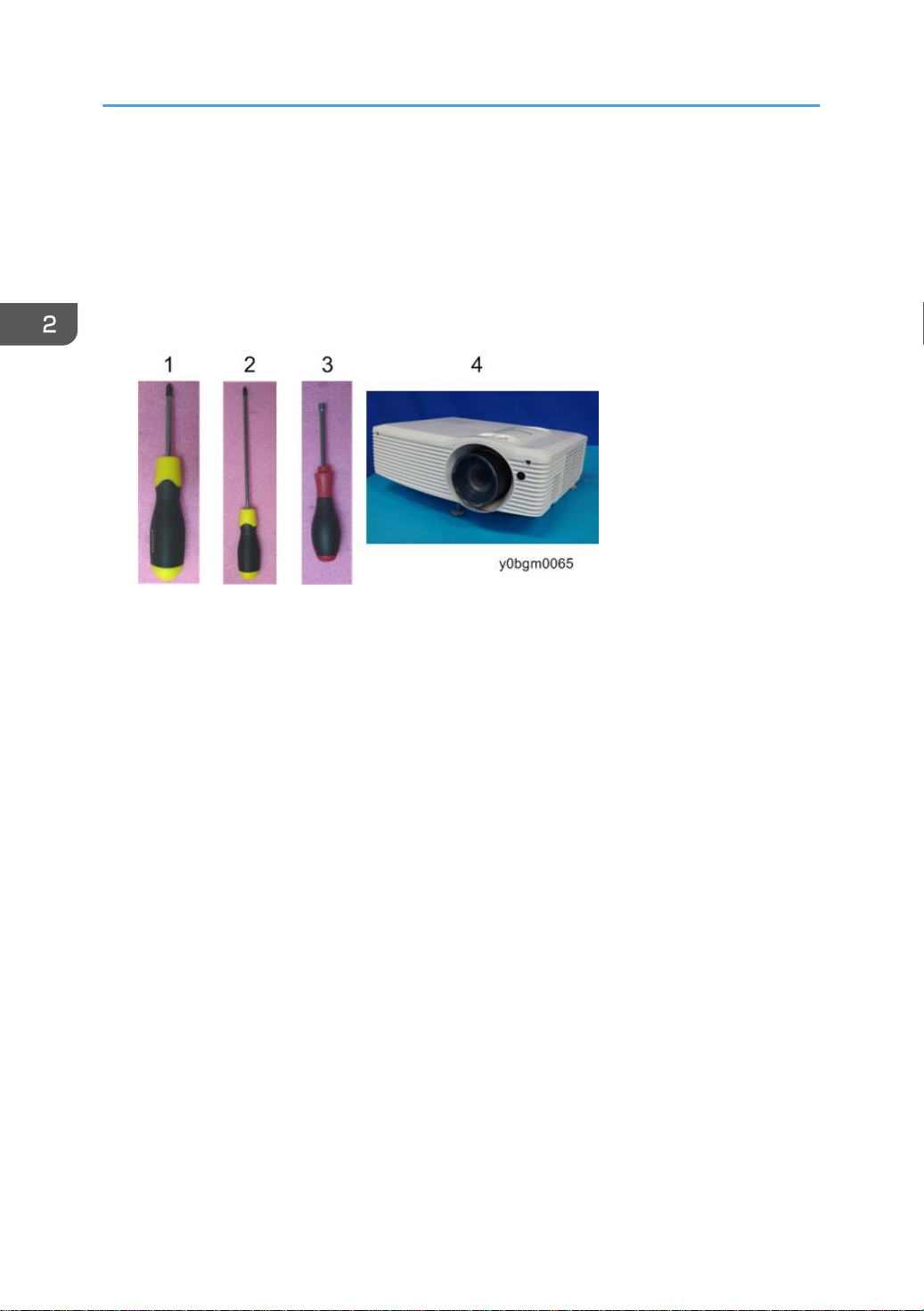
Equipment Needed
1. Screw bit (+): +No.2 or +No.1
2. Screw bit (+): +No.0
3. Hex sleeves 5 mm
4. Projector
22
Part Replacement
• This process is protective level II. Operators should wear electrostatic chains.
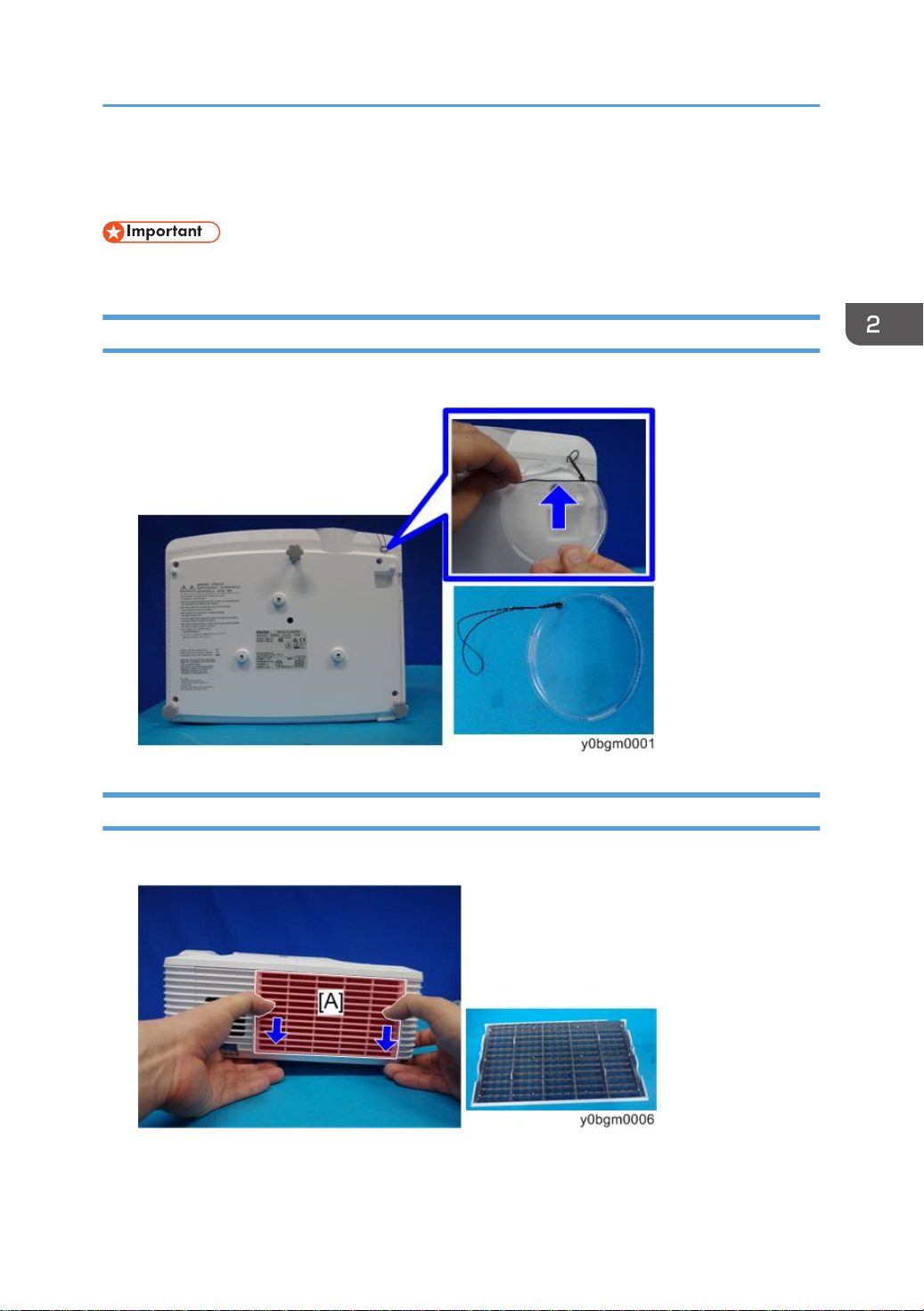
Lens Cap
1. Untie the string of the lens cap from the bottom cover.
Part Replacement
Filter
1. Remove the filter [A] from the right cover.
23
2. Replacement
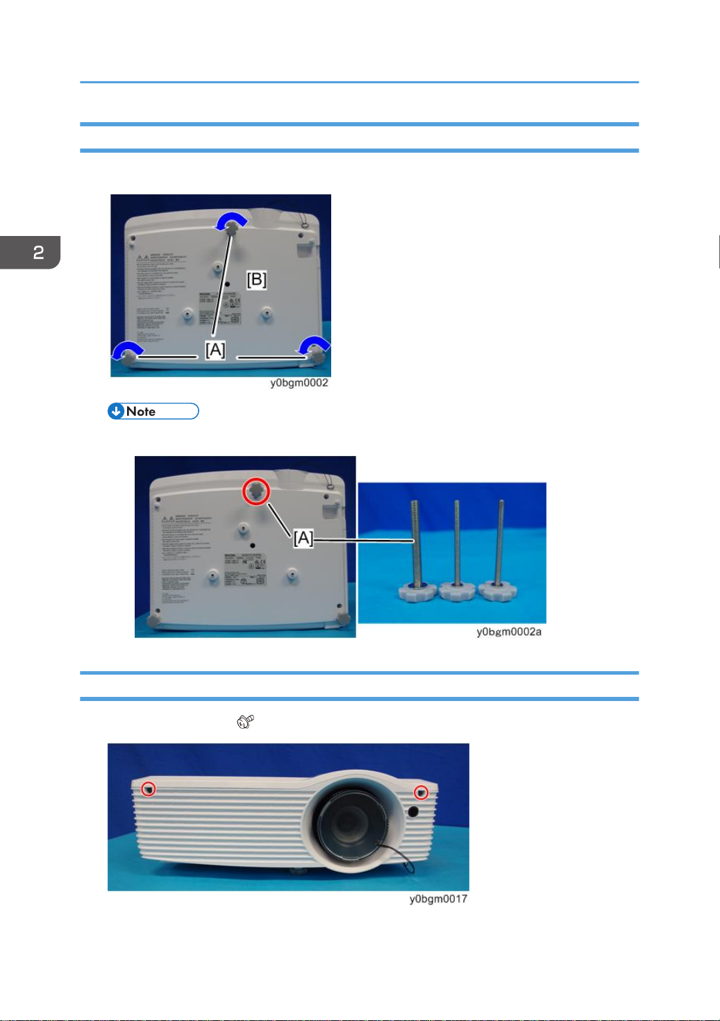
Adjustable Feet (Front x1, Rear x2)
1. Remove the 3 adjustable feet [A] from the bottom cover [B].
• The foot at the front [A] is thicker than the other feet.
Lamp Cover, Lamp Module
1. Loosen the 2 screws. ( ×2)
24
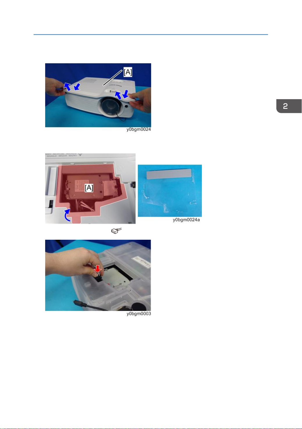
2. Remove the lamp cover [A].
3. Remove the protection sheet [A].
Part Replacement
4. Disconnect the connector. ( ×1)
25
2. Replacement
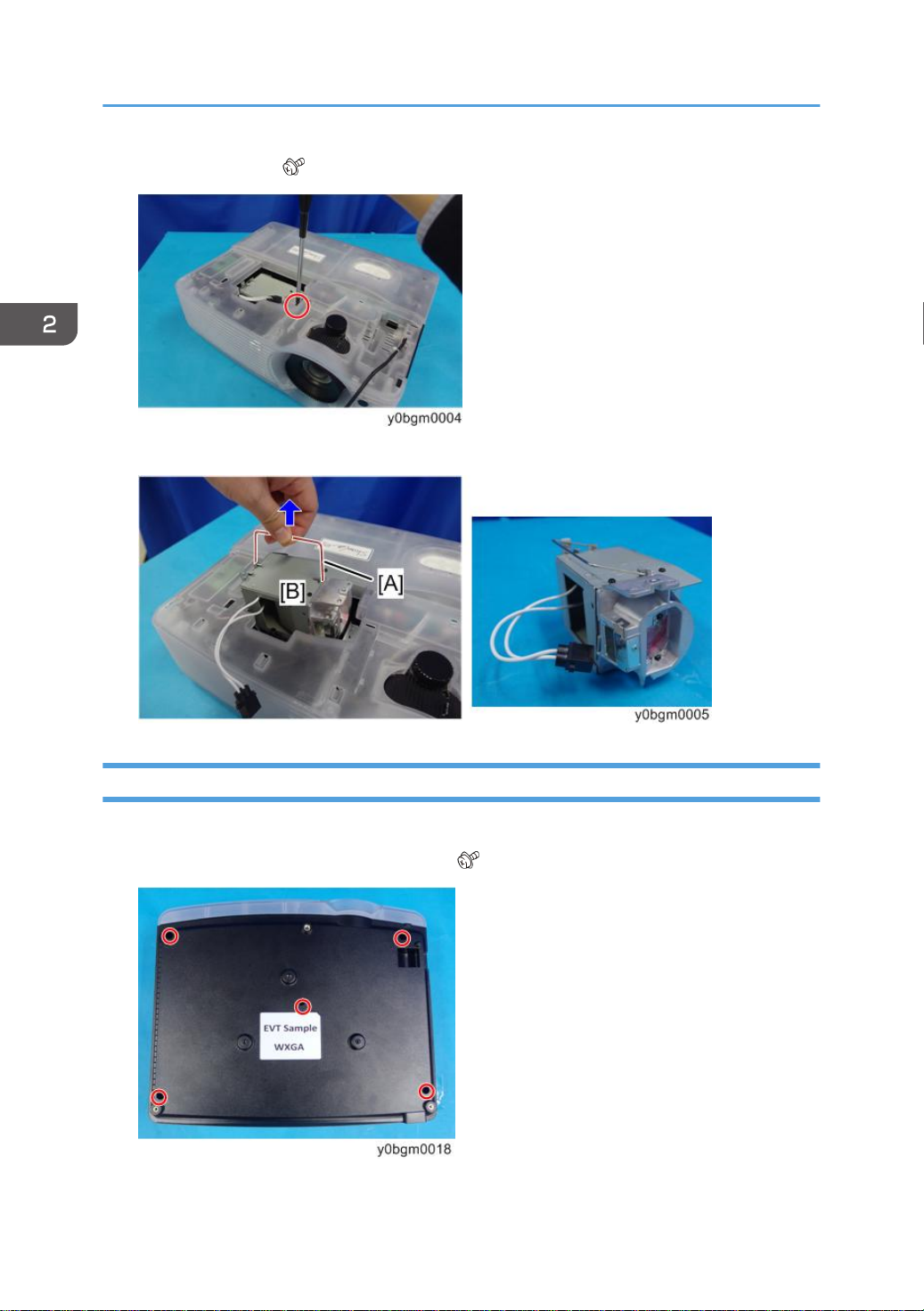
5. Loosen the screw. ( ×1)
6. Lift up the lamp handle [A] and remove the lamp module [B].
Top Cover (Including Mini HDMI Cable and Keypad Rubber)
1. Remove the lamp cover. (page 24 "Lamp Cover, Lamp Module")
2. Remove 5 screws from the bottom cover. ( ×5)
26
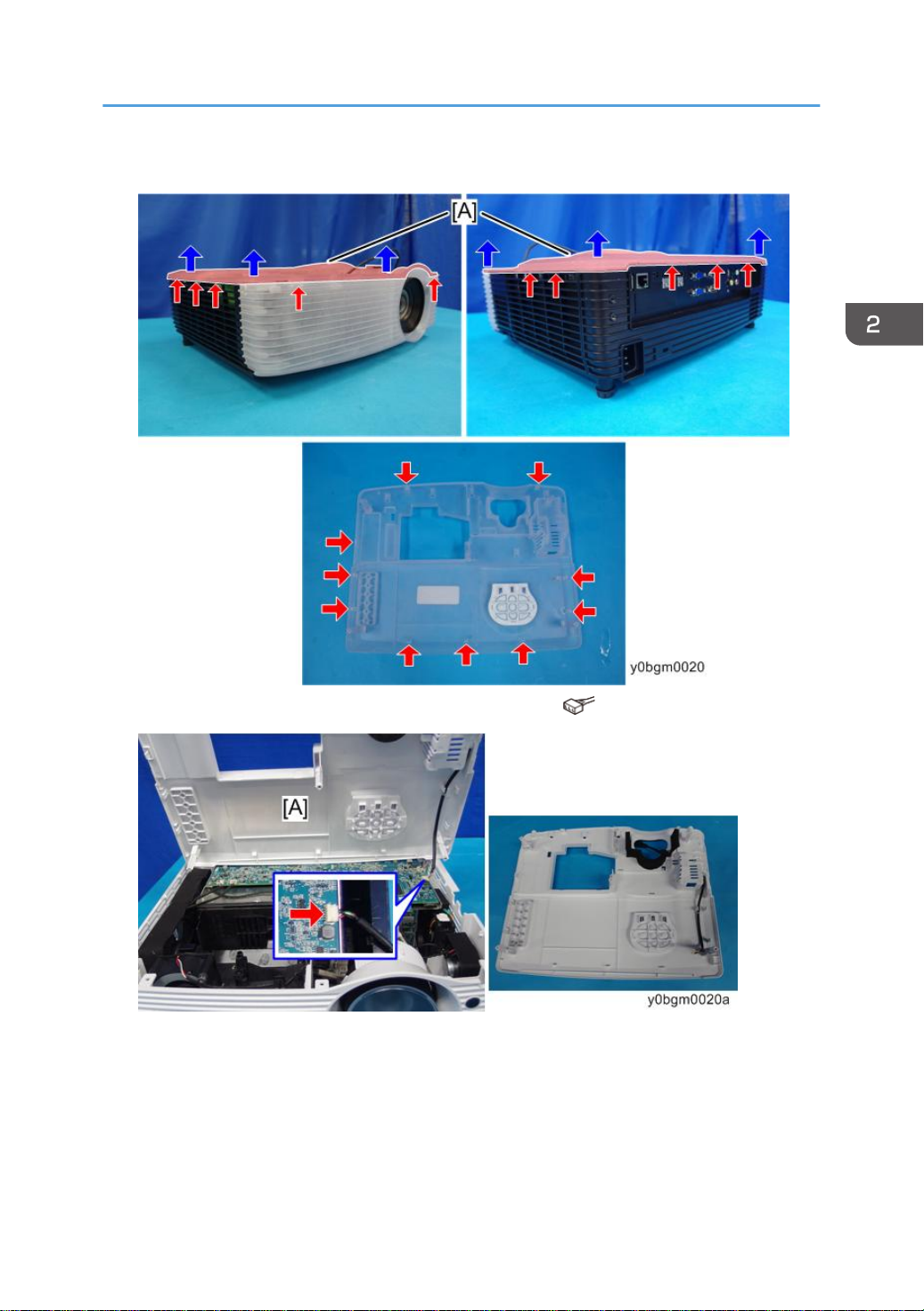
3. Lift up the top cover [A].(hook x 10)
Part Replacement
4. Disconnect the connector to separate the top cover [A]. ( ×1)
27
2. Replacement
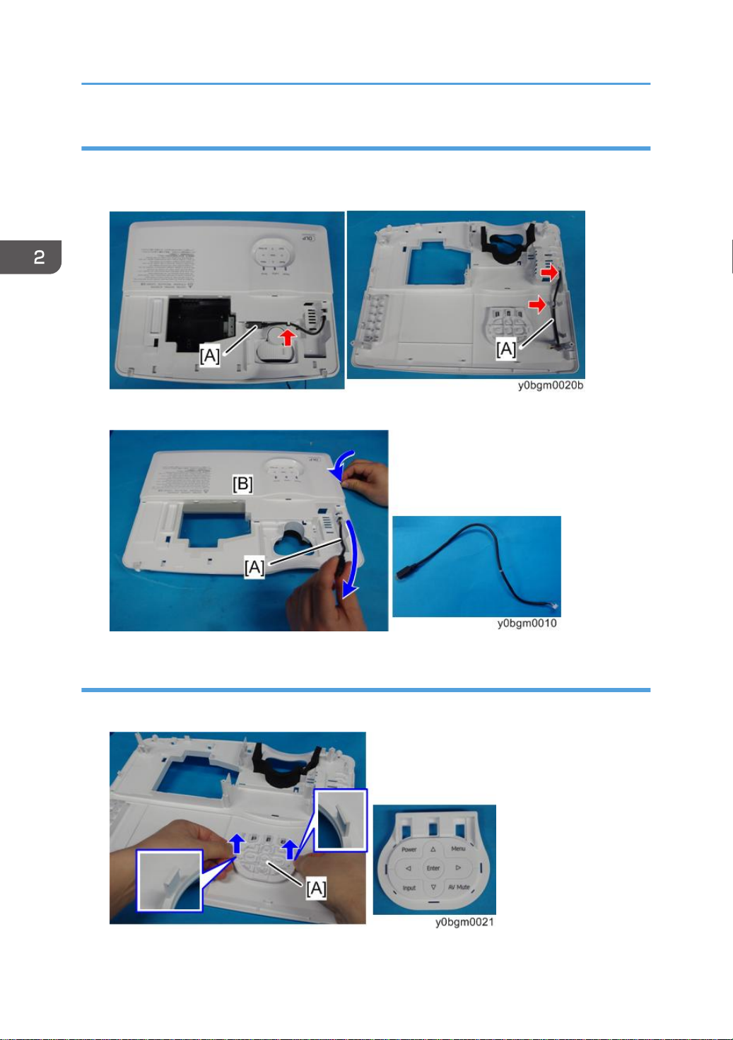
Mini HDMI Cable
1. Release the mini HDMI cable [A] from the cable guides on the top and bottom of the top
cover.
2. Pull out the mini HDMI Cable [A] from the top cover [B].
Keypad Rubber
1. Place the top cover upside down, and remove the keypad rubber [A]. (hook x 2)
28
 Loading...