

Ricoh PJ X5360N, PJ WX5350 Field Service Manual

Model Rigel-PJ1 nx/nw
Machine Codes:
Y015/Y016
Field Service Manual
6 January, 2012

Important Safety Notices
• RISK OF ELECTRIC SHOCK DO NOT OPEN
TO REDUCE THE RISK OF ELECTRIC SHOCK, DO NOT REMOVE COVER. NO USER-
•
SERVICEABLE PARTS INSIDE. REFER SERVICING TO QUALIFIED SERVICE PERSONNEL.
This symbol warns the user that uninsulated voltage within the unit may have sufficient
magnitude to cause electric shock. Therefore, it is dangerous to make any kind of
contact with any part inside of this unit.
This symbol alerts the user that important literature concerning the operation and
maintenance of this unit has been included.
Therefore, it should be read carefully in order to avoid any problems.
• HEATSINK MAY BE ENERGIZED. TEST BEFORE TOUCHING.
Heat sink located on the power board, is electrified.
•
Pay attention to this area.
During servicing carefully observe the following.
mark is putted on the primary heat sink.
OBSERVE ALL PRECAUTIONS
1.
Items and locations that require special care during servicing, such as the cabinet, chassis, and
parts are labelled with individual safety instructions. Carefully comply with these instructions and all
precautions in the instruction manual.
2. BE CAREFUL OF ELECTRIC SHOCK
The chassis carries an AC voltage. If you touch the chassis while it is still alive, you will get a severe
shock. If you think the chassis is alive, use an isolating transformer or gloves, or pull out the plug
before replacing any parts.
3. USE SPECIFIED PARTS
The components have been chosen for minimum flammability and for specific levels of resistance
value and withstand voltage. Replacement parts must match these original specifications. Parts
whose specifications are particularly vital to safe use and maintenance of the set is marked
the circuit diagrams and parts list.
Substitution of these parts can be dangerous for you and the customer, so use only specified parts.
REMOUNT ALL PARTS AND RECONNECT ALL WIRES AS ORIGINALLY INSTALLED
4.
For safety, insulating tape and tubes are used throughout, but some lift-off parts on the printed
wiring board require special attention.
on
1

All wires are positioned away from high-temperature and high-voltage parts, and, if removed for
servicing, they must be retuned precisely to their original positions.
LAMP
5.
Be very careful of the lamp because it generates high heat while it is used at high voltage. When
replacing the bulb, make sure it is cool enough.
6. LENS
Do not look into the lens during projection. This is important to avoid damage to the eyes.
7. SERVICING
At the time of repair or inspection services, use an earth band (wrist band), without fail.
8. RUN A COMPLETE SAFETY CHECK AT THE COMPLETION OF SERVICING
After completion of servicing, confirm that all screws, parts, and wiring, removed or disconnected
for servicing, have been returned to their original positions. Also examine if the serviced sections
and peripheral areas have suffered from any deterioration as a result of servicing. In addition,
check insulation between external metallic parts and blades of walloutlet plugs. This examination is
indispensable in confirming complete establishment of safety.
(Insulation check)
Pull out a plug from a wall outlet to disconnect the connection cable. Then turn on the POWER
switch. Use a 500V megger (Note 2) and confirm that the insulation resistance is 1M
between each terminal of the plug and exposed external metal (Note 1). If the measured value is
below the specified level, then it is necessary to inspect and fix the set.
or more
(Note 1)
Exposed external metal....RGB input terminals, control terminals, etc.
(Note 2)
If a 500V megger is not available for an unavoidable reason, then use a circuit tester or the like for
inspection.
2

Symbols and Trademarks
This manual uses several symbols and abbreviations. The meaning of those symbols and abbreviations
are as follows:
See or Refer to
Screw
Connector
Trademarks
Microsoft® and Windows® are registered trademarks of Microsoft Corporation in the United States
and /or other countries.
Other product names used herein are for identification purposes only and may be trademarks of their
respective companies. We disclaim any and all rights involved with those marks.
3

TABLE OF CONTENTS
Important Safety Notices...................................................................................................................................1
Symbols and Trademarks...................................................................................................................................3
Trademarks.....................................................................................................................................................3
1. Product Information
Specifications......................................................................................................................................................9
Overview..........................................................................................................................................................10
Front / Top...................................................................................................................................................10
Rear...............................................................................................................................................................11
Top Features.................................................................................................................................................12
Terminal Panel Features...............................................................................................................................13
Part Names of the Remote Control.............................................................................................................15
2. Installation
Installation Requirements.................................................................................................................................19
Fire and Shock Precautions.........................................................................................................................19
3. Replacement and Adjustment
Cautions for Maintenance Service.................................................................................................................25
Method of starting the set without TOP COVER and LAMP COVER.......................................................25
Special Tools....................................................................................................................................................28
Parts Replacement............................................................................................................................................31
Lamp Unit......................................................................................................................................................31
Filters.............................................................................................................................................................32
Port Cover for USB Wireless LAN Unit.......................................................................................................33
Top Cover.....................................................................................................................................................33
PCB Shutter...................................................................................................................................................35
Rear Panel and Speaker.............................................................................................................................36
PCB Main Ass'y............................................................................................................................................38
PCB Network................................................................................................................................................38
Lamp Fan......................................................................................................................................................39
OPT Base......................................................................................................................................................41
Assembling the lens holder (top)........................................................................................................42
IRIS Unit........................................................................................................................................................44
PS-Converter................................................................................................................................................45
LCD Fan 1.....................................................................................................................................................46
4

LCD Fan 2.....................................................................................................................................................48
PCB Remocon...............................................................................................................................................
Intake Temp Sensor.....................................................................................................................................50
Exhaust Temp Sensor...................................................................................................................................50
Exhaust Fan..................................................................................................................................................51
Thermostat....................................................................................................................................................52
PSU Fan........................................................................................................................................................55
Power Supply-Ballast...................................................................................................................................56
Power Supply-DC........................................................................................................................................56
Bottom Cover...............................................................................................................................................59
Replacement of Optical Parts..........................................................................................................................60
Polarizer-B....................................................................................................................................................60
Polarizer-G...................................................................................................................................................61
Polarizer-R....................................................................................................................................................63
Optical Parts Adjustment.............................................................................................................................63
Adjusting and fixing parts...................................................................................................................64
Adjustment of the optical axis (Shadow adjustment).......................................................................65
Adjustment of the polarization plate (Contrast adjustment).............................................................73
49
Electrical Adjustment........................................................................................................................................76
Procedures for the replacement of the PCB Main Ass’y...........................................................................77
Outline of adjustment procedules......................................................................................................77
PC control software for service..........................................................................................................78
Model-Specific Data Writing Procedure..........................................................................................91
Procedure for rewriting EDID data....................................................................................................94
Procedure for writing of a serial number and a model number....................................................103
Procedures for the replacement of the OPT Base...................................................................................106
4. System Maintenance
Firmware Upgrade........................................................................................................................................107
Upgrading the firmware...........................................................................................................................107
Functional Test................................................................................................................................................109
Connecting a Computer............................................................................................................................
Connecting an External Monitor..............................................................................................................112
Connecting a DVD Player or Other AV Equipment................................................................................113
109
5

Connecting Component Input..................................................................................................................114
Connecting HDMI Input............................................................................................................................115
Connecting to a Wired LAN.....................................................................................................................
Input signals...............................................................................................................................................118
Signal level........................................................................................................................................118
RGB signal frequencies....................................................................................................................118
HDMI digital signals.........................................................................................................................118
Component signals...........................................................................................................................118
Video input color system..................................................................................................................118
117
5. Troubleshooting
LED Display....................................................................................................................................................119
Indicator Messages...................................................................................................................................119
Power Indicator.................................................................................................................................119
Status Indicator.................................................................................................................................119
Lamp Indicator..................................................................................................................................120
Over-Temperature Protection..........................................................................................................121
Service Mode.................................................................................................................................................
List of functions...........................................................................................................................................122
Mode changeover....................................................................................................................................122
122
Expert mode......................................................................................................................................122
Service mode....................................................................................................................................123
How to withdraw from the mode.....................................................................................................123
Contents of display...........................................................................................................................124
Additional functions (extract)....................................................................................................................124
SETUP–EXPERT1 Tab........................................................................................................................124
SETUP–EXPERT2 Tab........................................................................................................................125
Security functions.......................................................................................................................................125
How to cancel the security functions...............................................................................................125
MM Viewer and Network Area...............................................................................................................126
List of functions..................................................................................................................................126
Additional Functions.........................................................................................................................127
Troubleshooting Guide..................................................................................................................................129
Operation check........................................................................................................................................129
6

Power block...............................................................................................................................................131
For Video....................................................................................................................................................
For Audio...................................................................................................................................................133
Error Log.........................................................................................................................................................134
Error Log Screen Image............................................................................................................................134
Displaying an error log screen........................................................................................................134
Service Information: Page-1............................................................................................................134
Service Information: Page-2............................................................................................................135
Service Information: Reset................................................................................................................136
Contents of Error Log (Page1) Display....................................................................................................137
Status Columns..................................................................................................................................137
PJ Usage Columns............................................................................................................................138
TEMP Columns..................................................................................................................................138
Other Columns..................................................................................................................................138
Contents of Error Log (Page2) Display....................................................................................................139
TEMP Columns..................................................................................................................................139
Lamp/Filter Clear Count..................................................................................................................139
Power ON/OFF Count....................................................................................................................139
132
Projector Hours Used........................................................................................................................139
Lamp Voltage: Indicated exceeding the Service Power................................................................140
Contents of Error Log (Reset) Display......................................................................................................140
ALL DATA...........................................................................................................................................140
7

8

1. Product Information
Specifications
See "Appendices" for the following information:
• General Specifications
9
1. Product Information
Overview
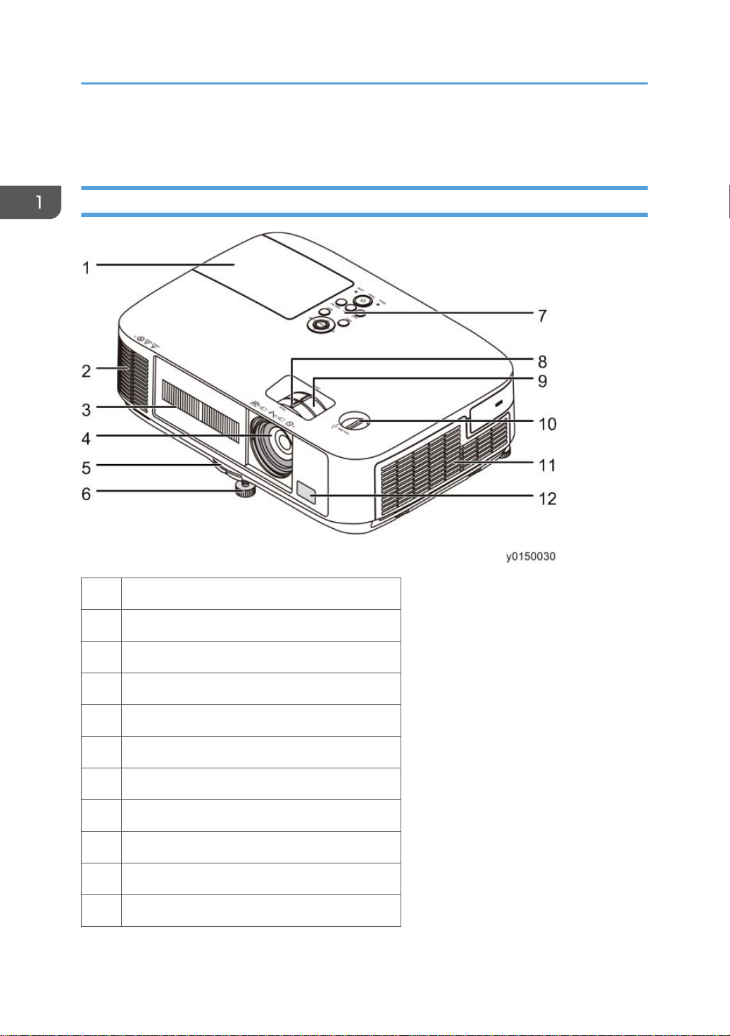
Front / Top
10
1 Lamp Cover
2 Ventilation (outlet)
3 Lens Cover
4 Lens
5 Adjustable Tilt Foot Lever
6 Adjustable Tilt Foot
7 Controls
8 Focus Lever
9 Zoom Lever
10 Lens Shift Dial (Vertical)
11 Ventilation (inlet) / Filter Cover
12 Remote Sensor
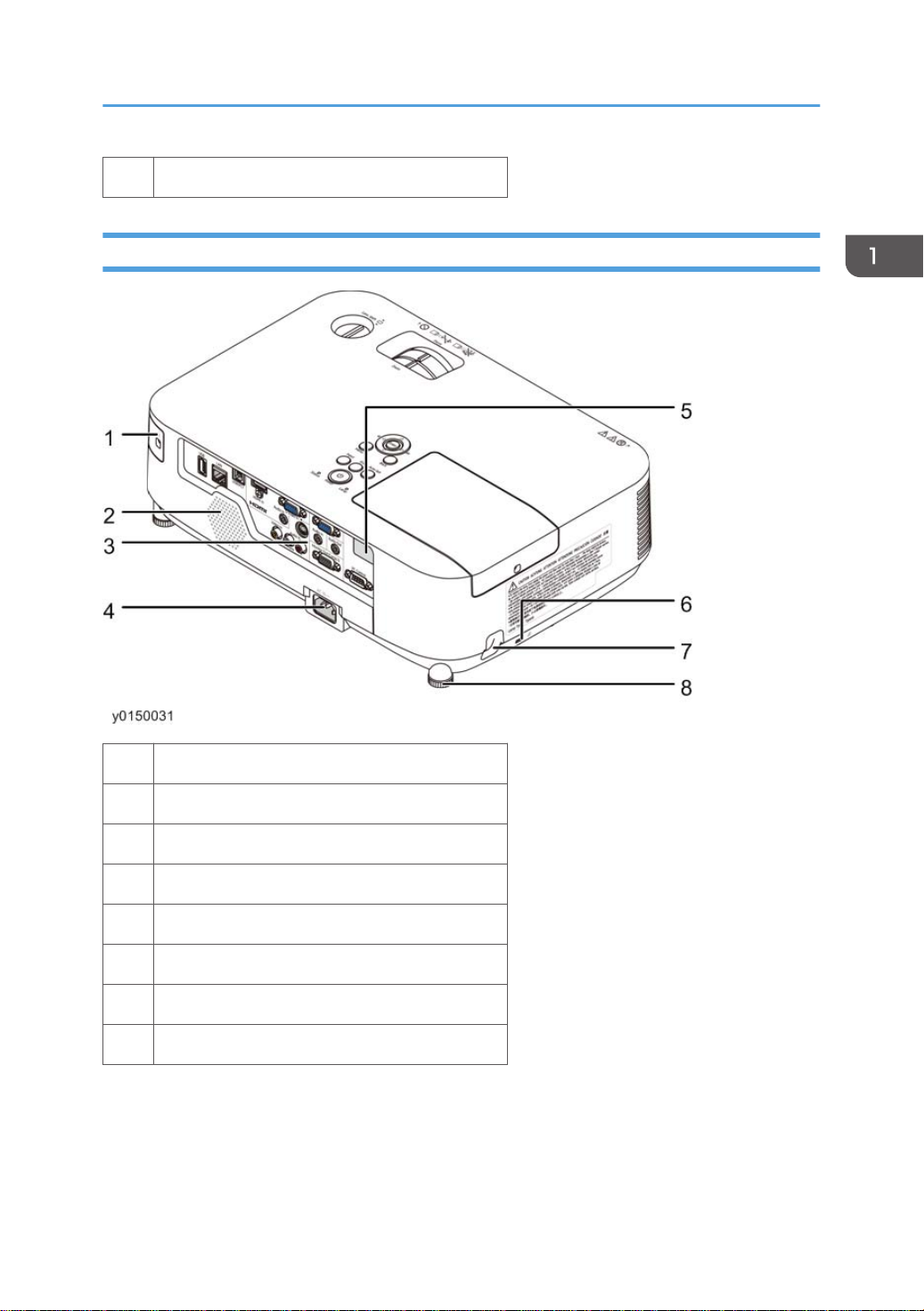
Rear
Overview
1 Port Cover for USB Wireless LAN Unit
2 Monaural Speaker
3 Terminal Panel
4 AC Input
5 Remote Sensor
6 Built-in Security Slot
7 Security chain opening
8 Rear Foot
11
1. Product Information
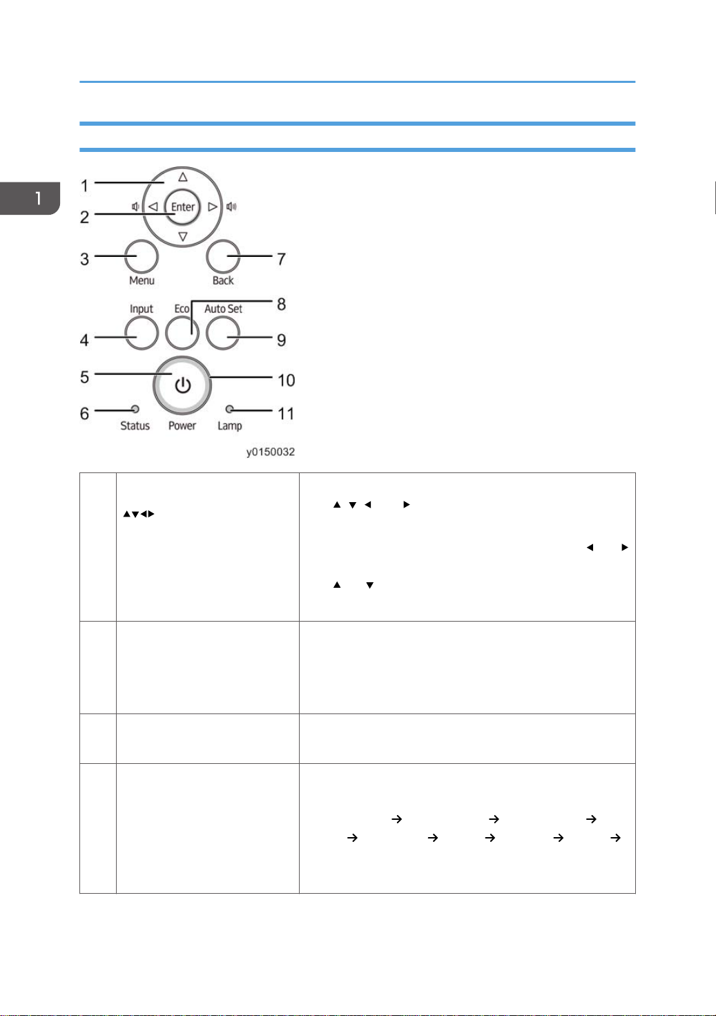
Top Features
Buttons
Used for both volume
1
adjustment and trapezoid
correction (Keystone Buttons).
2 Enter Button
3 Menu Button
4 Input Button
• While an on-screen menu is displayed, you can use the
, , , and buttons to select the item you want to set
or adjust.
When the on-screen menu is not displayed, the
•
buttons can be used to adjust the volume level, and the
and buttons can be used to adjust the trapezoid in
the vertical direction.
Proceeds to the next hierarchical menu in the currently
displayed on-screen menu.
Applies the selected item while the confirmation message is
displayed.
Displays an on-screen menu for setting or adjusting a variety
of items.
Detects the signal input.
Automatically checks for signal inputs in the following order:
[COMPUTER 1]
[HDMI] [DisplayPort] [VIDEO] [S-VIDEO] [Viewer]
[COMPUTER 1]. If it detects a signal input, it projects the
input.
[COMPUTER 2] [COMPUTER 3]
and
12
Turn the projector on and then off (standby).
Overview
5 Power Button
6 Status Indicator p.119
7 Back Button
8 Eco Button Displays the screen for selecting the lamp power level.
9 Auto set Button
10 Power Indicator
11 Lamp Indicator p.119
To turn the projector off (standby), then press the Power
button one time. When the confirmation message appears
on the screen, press the Power button again.
Returns to the previous hierarchical menu in the currently
displayed on-screen menu. When the cursor is placed over
the main menu, the menu closes. When a confirmation
message appears, the operation is canceled.
Automatically adjust the projector to an optimal state for
projection of a computer screen image.
p.119
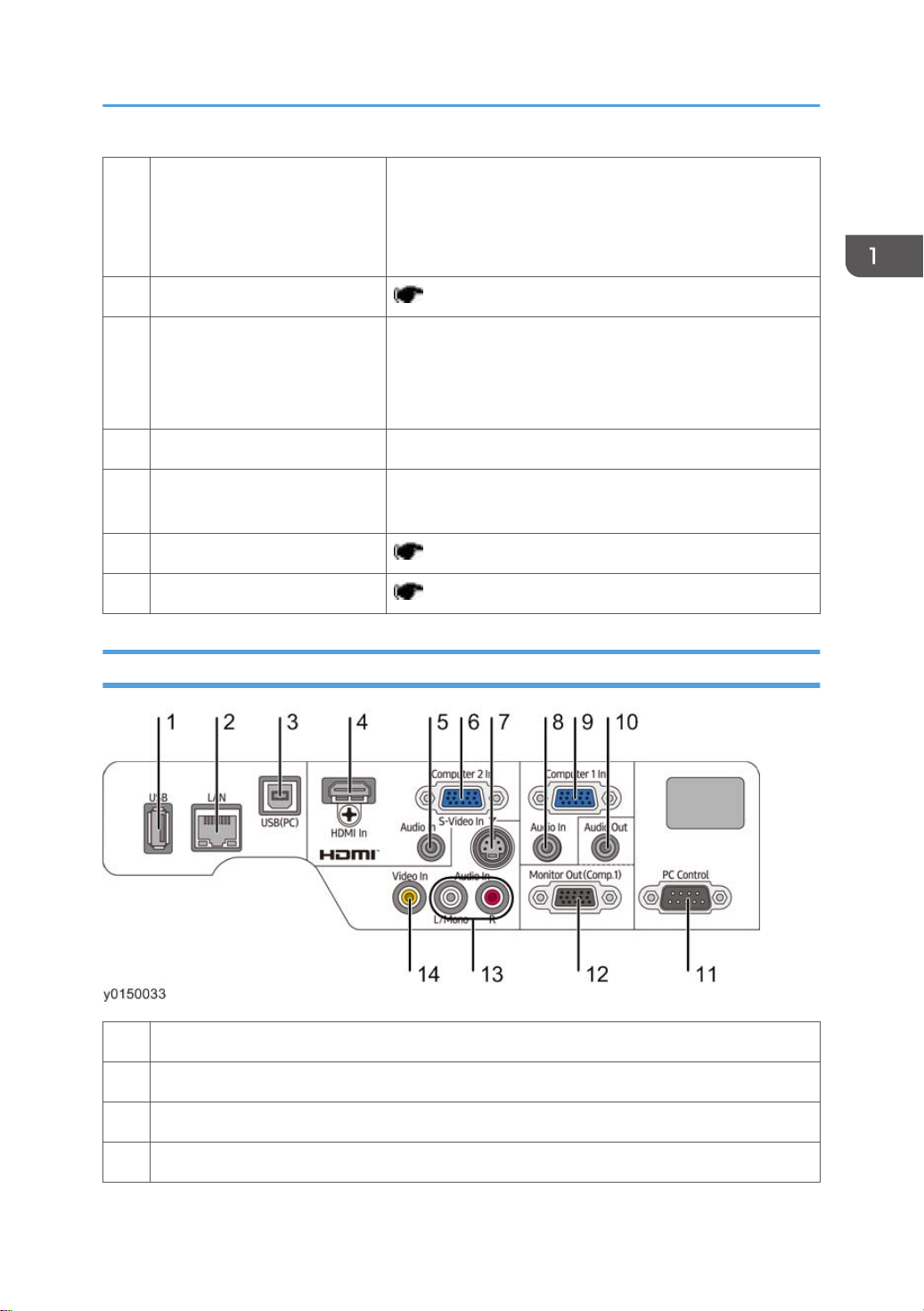
Terminal Panel Features
1 USB Port (Type A)
2 LAN Port (RJ-45)
3 USB (PC) Port (Type B)
4 HDMI In Connector (Type A)
13

1. Product Information
5 Computer 2 Audio In Mini Jack (Stereo Mini)
6 Computer 2 In / Component Input Connector (Mini D-Sub 15 Pin)
7 S-Video In Connector (Mini DIN 4 Pin)
8 Computer 1 Audio In Mini Jack (Stereo Mini)
9 Computer 1 In / Component Input Connector (Mini D-Sub 15 Pin)
10 Audio Out Mini Jack (Stereo Mini)
11 PC Control Port (D-Sub 9 Pin)
12 Monitor Out (Comp.1) Connector (Mini D-Sub 15 Pin)
13 Video/S-Video Audio In (L/Mono, R) Connectors (RCA)
14 Video In Connector (RCA)
14
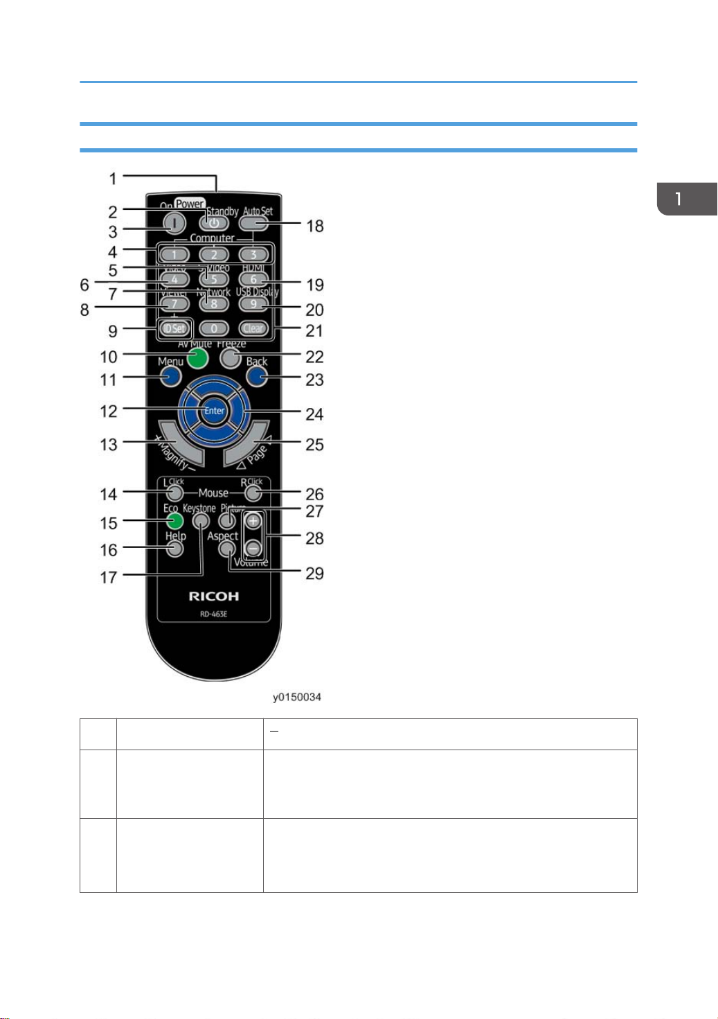
Part Names of the Remote Control
Overview
1 Infrared Transmitter
2 Power Standby Button
3 Power On Button
Pressing the Power button once displays the power-off confirmation
message. Pressing the Power button a second time turns the
projector off (standby).
Confirm that the projector is in standby (the Power indicator is lit
orange*), and then turn it on.
* When Standby mode is set to "Normal".
15

1. Product Information
4 Computer 1/2/3 Button
Select the COMPUTER1/2 input or a component.
(Computer 3 button is not available.)
5 S-Video Button Select the S-VIDEO input.
6 Video Button Select the VIDEO input.
7 Network Button Select the Network.
8 Viewer Button Select the Viewer.
The remote controller that comes with this projector can be used to
9 ID Set Button
control multiple projectors. These buttons are used to set the control
ID of an individual projector.
10 AV Mute Button
11 Menu Button
Turns off both video and audio temporarily. Pressing the button
again turns the video and audio back on.
Displays an on-screen menu for setting or adjusting a variety of
items.
Proceeds to the next hierarchical menu in the currently displayed
on-screen menu.
12 Enter Button
Applies the selected item while the confirmation message is
displayed.
16
13 Magnify (+)(−) Button Used to zoom in and out on the screen.
14 L Click Button
*1
Used when the machine is connected to a computer via a USB
cable. Acts as the left mouse button.
15 Eco Button Displays the screen for selecting the lamp power level.
16 Help Button Displays the information screen.
17 Keystone Button Displays the screen for adjusting the trapezoid.
18 Auto Set Button
Automatically adjust the projector to an optimal state for projection
of a computer screen image.
19 HDMI Button Select the HDMI input.
20 USB Display Button Select the USB Display.
Numeric Keypad
21
Button/Clear Button
Overview
The remote controller that comes with this projector can be used to
control multiple projectors. These buttons are used to enter the ID
(or set the control ID) of an individual projector.
The Clear button can be used to clear the set control ID.
22 Freeze Button
23 Back Button
*2
24
25 Page / Button
26 R Click Button
Button
*1
*1
27 Picture Mode Button
Displays the current video image as a still image. Pressing the
button again returns to normal video display.
Returns to the previous hierarchical menu in the currently displayed
on-screen menu. When the cursor is placed over the main menu,
the menu closes. When a confirmation message appears, the
operation is canceled.
Used to adjust display position when the screen is enlarged by
using the partial enlargement button or by performing an operation
in the on-screen menu .
This button is also used as the computer mouse (remote mouse)
when the machine is connected to a computer via a USB cable.
Used to switch the viewer between thumbnail views. This button is
also used when the machine is connected to a computer via a USB
cable.
Used when the machine is connected to a computer via a USB
cable. Acts as the right mouse button.
Each time the button is pressed in the on-screen menu, the picture
adjustment item displayed in [PICTURE] of the [ADJUST] menu
changes. The first item is [PRESET], followed by [CONTRAST],
[BRIGHTNESS], [SHARPNESS], [COLOR SATURATION], and
finally [TINT].
Adjusts the volume of the internal speaker. Also adjusts the volume
28 Volume (+)(−) Button
of output sent to the audio output port. Pressing the button again
resets the volume.
29 Aspect Button Displays a set of aspect adjustment items.
Used to operate the computer when the mouse receiver is connected to the computer.
*1
*2 Used as the computer mouse when the mouse receiver is connected to the computer.
17

1. Product Information
18
2. Installation
Installation Requirements
• Do not use any other object than the projector’s sliding lens cover to cover the lens while the
projector is on.
• Doing so can cause the object to get extremely hot, and possibly resulting in a fire or damage due
to the heat emitted from the light output.
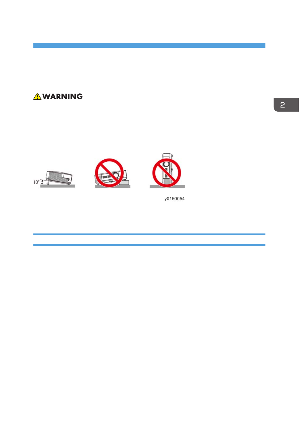
Place the projector in a horizontal position
The tilt angle of the projector should not exceed 10 degrees, nor should the projector be installed in any
way other than the desktop and ceiling mount, otherwise lamp life could decrease dramatically.
Fire and Shock Precautions
• Ensure that there is sufficient ventilation and that vents are unobstructed to prevent the build-up of
heat inside your projector. Allow at least 4 inches (10cm) of space between your projector and a
wall.
Do not try to touch the ventilation outlet on the left front (when seen from the front) as it can become
•
heated while the projector is turned on and immediately after the projector is turned off. Parts of the
projector may become temporarily heated if the projector is turned off with the Power button or if
the AC power supply is disconnected during normal projector operation.
Use caution when picking up the projector.
• Prevent foreign objects such as paper clips and bits of paper from falling into your projector. Do
not attempt to retrieve any objects that might fall into your projector. Do not insert any metal objects
such as a wire or screwdriver into your projector. If something should fall into your projector,
disconnect it immediately and have the object removed by a qualified service personnel.
• Do not place any objects on top of the projector.
• Do not touch the power plug during a thunderstorm. Doing so can cause electrical shock or fire.
19

2. Installation
• The projector is designed to operate on a power supply of 100-240V AC 50/60 Hz. Ensure that
your power supply fits this requirement before attempting to use your projector.
Do not look into the lens while the projector is on. Serious damage to your eyes could result.
•
• Keep any items (magnifying glass etc.) out of the light path of the projector. The light path being
projected from the lens is extensive, therefore any kind of abnormal objects that can redirect light
coming out of the lens, can cause an unpredictable outcome such as a fire or injury to the eyes.
• Do not place any objects, which are easily affected by heat, in front of a projector exhaust vent.
Doing so could lead to the object melting or getting your hands burned from the heat that is emitted
from the exhaust.
• Handle the power cord carefully. A damaged or frayed power cord can cause electric shock or
fire.
• Do not use any power cord other than the one supplied with the projector.
• Do not bend or tug the power cord excessively.
• Do not place the power cord under the projector, or any heavy object.
• Do not cover the power cord with other soft materials such as rugs.
• Do not heat the power cord.
• Do not handle the power plug with wet hands.
• Turn off the projector, unplug the power cord and have the projector serviced by a qualified
service personnel under the following conditions:
• When the power cord or plug is damaged or frayed.
• If liquid has been spilled into the projector, or if it has been exposed to rain or water.
• If the projector does not operate normally when you follow the instructions described in this
user’s manual.
• If the projector has been dropped or the cabinet has been damaged.
• If the projector exhibits a distinct change in performance, indicating a need for service.
• Disconnect the power cord and any other cables before carrying the projector.
• Turn off the projector and unplug the power cord before cleaning the cabinet or replacing the
lamp.
• Turn off the projector and unplug the power cord if the projector is not to be used for an extended
period of time.
• When using a LAN cable (only models with the RJ-45 LAN port):
For safety, do not connect to the connector for peripheral device wiring that might have excessive
voltage.
20
• Do not use the tilt-foot for purposes other than originally intended. Misuses such as gripping
the tilt-foot or hanging on the wall can cause damage to the projector.

Installation Requirements
• Do not send the projector in the soft case by parcel delivery service or cargo shipment. The
projector inside the soft case could be damaged.
Select [HIGH] in Fan mode if you continue to use the projector for consecutive days. (From the
•
menu, select [SETUP]
Do not try to touch the ventilation outlet on the left front (when seen from the front) as it can
•
[OPTIONS(1)] [FAN MODE] [HIGH].)
become heated while the projector is turned on and immediately after the projector is turned
off.
• Do not turn off the AC power for 60 seconds after the lamp is turned on and while the Power
indicator is blinking blue. Doing so could cause premature lamp failure.
Remote Control Precautions
• Handle the remote control carefully.
• If the remote control gets wet, wipe it dry immediately.
• Avoid excessive heat and humidity.
• Do not short, heat, or take apart batteries.
• Do not throw batteries into fire.
• If you will not be using the remote control for a long time, remove the batteries.
• Ensure that you have the batteries’ polarity (+/−) aligned correctly.
• Do not use new and old batteries together, or use different types of batteries together.
• Dispose of used batteries according to your local regulations.
Note for US Residents
The lamp in this product contains mercury. Please dispose according to Local, State or Federal
Laws.
Lamp Replacement
• Use the specified lamp for safety and performance.
• To replace the lamp, follow all instructions provided on User’s Manual (
Replacing the Lamp
and the Filters (page 146)).
Be sure to replace the lamp and filter when the message [THE LAMP HAS REACHED THE END OF
•
ITS USABLE LIFE. PLEASE REPLACE THE LAMP AND FILTER.] appears. If you continue to use the
lamp after the lamp has reached the end of its usable life, the lamp bulb may shatter, and pieces of
glass may be scattered in the lamp case. Do not touch them as the pieces of glass may cause injury.
If this happens, contact your dealer for lamp replacement.
A Lamp Characteristic
The projector has a high-pressure mercury lamp as a light source.
A lamp has a characteristic that its brightness gradually decreases with age. Also repeatedly
turning the lamp on and off will increase the possibility of its lower brightness.
21

2. Installation
• DO NOT TOUCH THE LAMP immediately after it has been used. It will be extremely hot. Turn the
projector off and then disconnect the power cord. Allow at least one hour for the lamp to cool
before handling.
When removing the lamp from a ceiling-mounted projector, make sure that no one is under the
•
projector. Glass fragments could fall if the lamp has been burned out.
About High Altitude mode
• Set [FAN MODE] to [HIGH ALTITUDE] when using the projector at altitudes approximately
5500 feet/1600 meters or higher.
Using the projector at altitudes approximately 5500 feet/1600 meters or higher without
setting to [HIGH ALTITUDE] can cause the projector to overheat and the protector could shut
down. If this happens, wait a couple minutes and turn on the projector.
• Using the projector at altitudes less than approximately 5500 feet/1600 meters and setting
to [HIGH ALTITUDE] can cause the lamp to overcool, causing the image to flicker. Switch
[FAN MODE] to [AUTO].
• Using the projector at altitudes approximately 5500 feet/1600 meters or higher can shorten
the life of optical components such as the lamp.
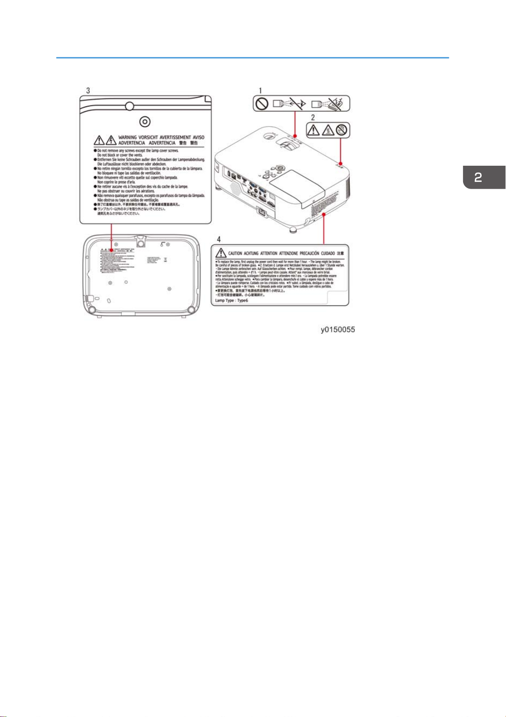
Safety Labels of This Machine
1. Do not look into the lens while the projector is on. Serious damage to your eyes could result.
Do not use any other object than the projector's sliding lens cover to cover the lens while the
projector is on. Doing so can cause the object to get extremely hot, and possibly resulting in a
fire or damage due to the heat emitted from the light output.
2. Do not try to touch the ventilation outlet on the left front (when seen from the front) as it can
become heated while the projector is turned on and immediately after the projector is turned
off. Parts of the projector may become temporarily heated if the projector is turned off with the
Power button or if the AC power supply is disconnected during normal projector operation.
Use caution when picking up the projector.
3. Do not remove any screws except the lamp cover screws. Do not block or cover the vents.
4. To replace the lamp, first unplug the power cord then wait for more than 1 hour. The lamp
might be broken. Be careful of pieces of broken glass.
22
Installation Requirements
23

2. Installation
24
3. Replacement and Adjustment
Cautions for Maintenance Service
Method of starting the set without TOP COVER and LAMP COVER
How to start the set under the condition that the LAMP COVER and TOP COVER are removed
The Lamp Cover switch of this model is mounted on the PCB Main Ass'y.
The set cannot be started if the LAMP COVER and TOP COVER are left removed.
This is because the Lamp Cover switch can be turned OFF only if the LAMP COVER is removed.
In addition, the PCB Shutter (lens cover) is installed on the Top Cover. When the Top Cover is
removed, the status of AV mute is assumed.
Follow the steps shown below when intending to start up the set under the condition that the LAMP
COVER and TOP COVER are removed.
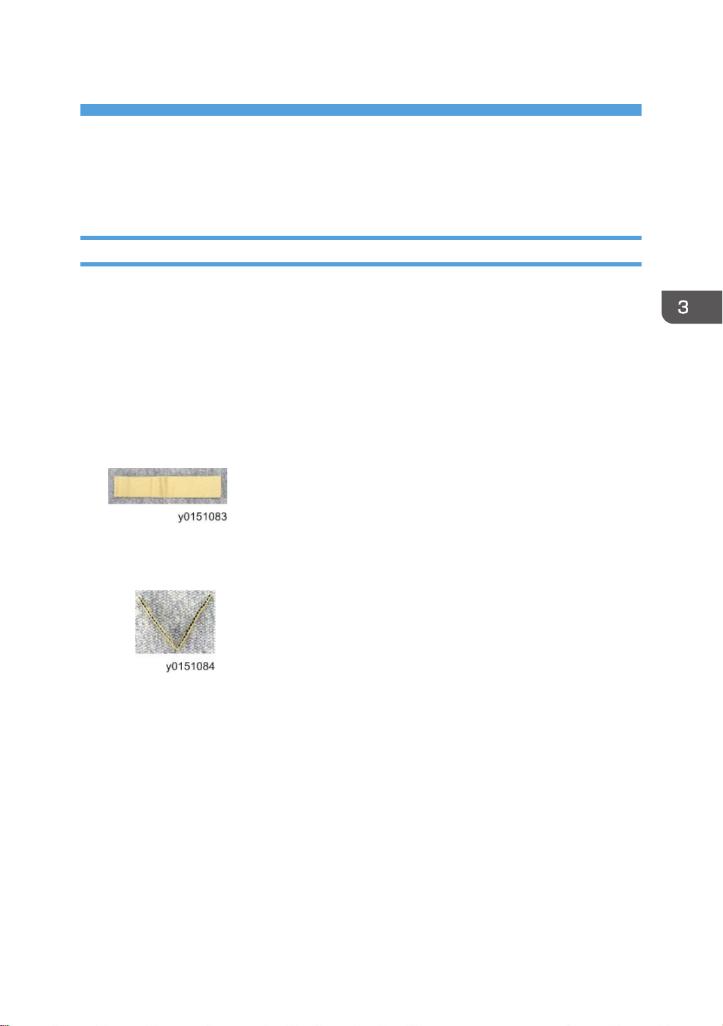
1. Provide for carton (or cardboard paper)
Length: 35 - 40 (mm), Depth: 100 - 120 (mm), Thickness: 1 - 2 (mm)
25
3. Replacement and Adjustment
2. Fold the carton (or cardboard paper) in the center in Character V.
26
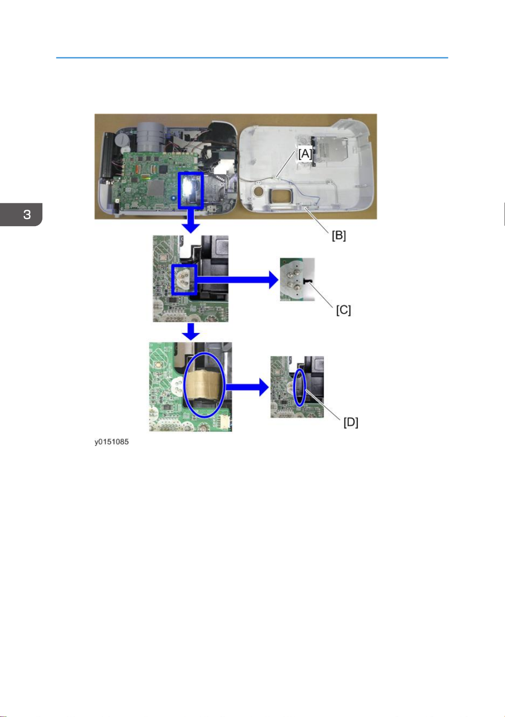
[A] : 3P extension board and 3P extension connector
[B] : The lens cover is left opened.
[C] : LAMP COVER SWITCH (ON by PUSH)
[D] : Insert the carton
3. Insert the carton (or cardboard paper) folded in Character V in the right side of the
Lamp Cover switch.
(Insert it along the Lamp Cover switch.)
4. Connect the PCB Main Ass'y and the PCB Shutter with the 3P extension board and
extension connector.
5. The lens cover should be left opened.
Cautions for Maintenance Service
• When installing the LAMP COVER and TOP COVER on the set, the TOP COVER only should be
mounted first. Then, the LAMP COVER can be mounted.
If the installation work is carried out in the state that the LAMP COVER is mounted on the TOP
•
COVER, the Lamp Cover switch may be damaged by the embossed part of the LAMP COVER.
27
3. Replacement and Adjustment
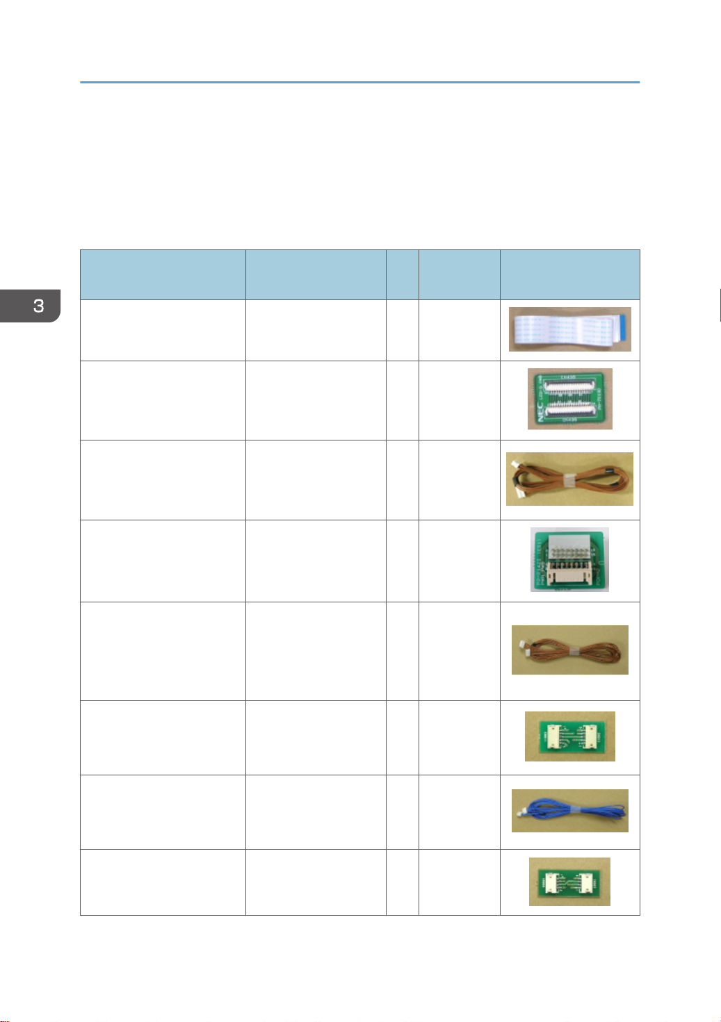
Special Tools
RS232C cable (cross)
•
• LAN cable (Category 5 or higher)
Adjusting jig for Adjustment of the optical axis
Item name Application
Extension connector (40P)
Extension connector PWB
(40P)
Extension connector (16P)
Extension connector PWB
(16P)
Extension connector (5P)
For LCD PANEL
(R/G/B : 600mm)
For LCD PANEL
(R/G/B)
For Power supply
(POPW : 500mm)
POWER SUPPLY-DC
For Power supply
(POWER SUPPLY-DC)
For Power supply
(POLC : 900mm)
POWER SUPPLYBALLAST
Q't
Part No. Photo taken from life
y
3 Y0135213
3 Y0135214
1 Y0155209
1 Y0155210
1 Y0135207
28
Extension connector PWB
(5P)
Extension connector (4P)
Extension connector PWB
(4P)
For Power supply
(POWER SUPPLYBALLAST)
For FAN
(POF1/POF3/POF4 :
900mm)
For FAN
(POF1/POF3/POF4)
1 Y0135208
3 Y0135205
3 Y0135206
 Loading...