

Ricoh pif500 Service Manual

KAISER1 PRINTER CONTROLLER
(Machine Code: H144-54, 55)
PRINTER INTERFACE TYPE 500
November 29, 1999
Subject to change

TABLE OF CONTENTS
1. OVERALL MACHINE INFORMATION........................................1-1
1.1 SPECIFICATIONS..................................................................................... 1-1
1.1.1 GENERAL SPECIFICATIONS.......................................................... 1-1
1.1.2 SUPPORTED PAPER SIZES........................................................... 1-2
1.2 SOFTWARE ACCESSORIES.................................................................... 1-3
1.2.1 PRINTER DRIVERS......................................................................... 1-3
1.2.2 UTILITY SOFTWARE....................................................................... 1-3
1.3 BLOCK DIAGRAM..................................................................................... 1-4
2. DETAILED SECTION DESCRIPTIONS.......................................2-1
2.1 CONTROLLER FUNCTIONS .................................................................... 2-1
2.1.1 IMAGE DATA PROCESSIING.......................................................... 2-1
2.1.2 PAPER SIZE/TYPE DETECTION AND SELECTION....................... 2-2
2.1.3 PAPER SOURCE SELECTION........................................................ 2-3
2.1.4 RESET OPERATIONS..................................................................... 2-4
2.1.5 ENERGY SAVER MODE.................................................................. 2-4
3. INSTALLATION PROCEDURES.................................................3-1
3.1 PRINTER CONTROLLER.......................................................................... 3-1
3.2 NETWORK INTERFACE BOARD (NIB).................................................... 3-5
3.3 MEMORY (DRAM SIMM) .......................................................................... 3-7
4. SERVICE TABLES......................................................................4-1
4.1 PRECAUTION ........................................................................................... 4-1
4.2 SERVICE MODES..................................................................................... 4-1
4.2.1 HOW TO ENTER THE SERVICE MODES....................................... 4-1
4.2.2 SERVICE MODE TABLE.................................................................. 4-2
4.2.3 PRINT LOG ...................................................................................... 4-4
4.2.4 PRINTER ID ..................................................................................... 4-9
4.2.5 SERVICE TOOL MENUS ............................................................... 4-11
4.3 NVRAM RESET PROCEDURES............................................................. 4-14
4.4 DOWNLOADING NEW CONTROLLER SOFTWARE............................. 4-14
4.4.1 OVERVIEW .................................................................................... 4-14
4.4.2 DOWNLOADING NEW FIRMWARE FROM AN IC CARD............. 4-15
4.5 USER MENU ........................................................................................... 4-17
4.6 DIAGNOSTIC TEST MODES .................................................................. 4-18
4.6.1 OVERVIEW .................................................................................... 4-18
4.6.2 POWER-UP DIAGNOSTIC MODE................................................. 4-18
4.6.3 DETAILED DIAGNOSTIC MODE................................................... 4-19
4.6.4 DIAGNOSTIC TEST DETAILS ....................................................... 4-20
i

5. TROUBLESHOOTING ................................................................ 5-1
5.1 OPERATOR ERRORS .............................................................................. 5-1
5.2 PRINTER ENGINE SC CODES................................................................. 5-6
5.3 DIAGNOSTIC ERROR CODES................................................................. 5-8
5.3.1 DIAGNOSTIC ERROR CODE TABLE.............................................. 5-8
ii

29 November, 1999 OVERALL MACHINE INFORMATION
1. OVERALL MACHINE INFORMATION
1.1 SPECIFICATIONS
1.1.1 GENERAL SPECIFICATIONS
Print Speed (Max.):
Printer Languages:
Print Resolution:
Memory (SIMM):
Resident Fonts:
Host Interfaces:
15 ppm (600 dpi, A4 sideways)
PCL 6 and PCL 5e
PCL 6 – 600 dpi
PCL 5e – 300/600 dpi
8 MB (standard)
40 MB (maximum)
NOTE:
PCL: 45 outline fonts and 1 bitmap font
IEEE1284/ECP parallel interface x 1 (standard)
Ethernet 10BaseT/100BaseTX network interface x 1
(optional)
NOTE:
There is 1 slot for a 16 or 32 MB SIMM.
Refer to the NIB service manual for details.
Overall
Information
Other Interfaces:
SIMM interface x 1 (for optional memory)
1-1
SPECIFICATIONS 29 November, 1999
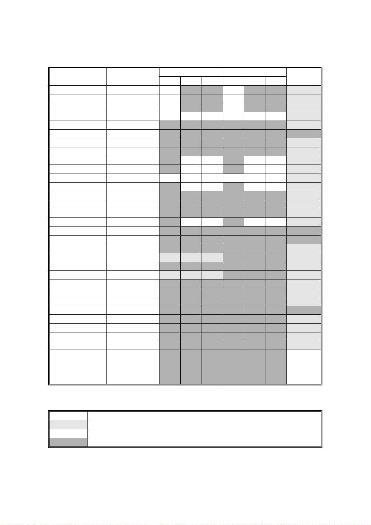
1.1.2 SUPPORTED PAPER SIZES
Paper Size (W x L)
Tray 1 Tray 2/3
NA EU Asia NA EU Asia
By-pass
Ledger 11 x 17" Y N NYN N Y
Legal 8.5 x 14" Y N NYN N Y
Letter SEF 8.5 x 11" Y N NYN N Y
Letter LEF 11 x 8.5" Y Y Y Y Y Y Y
Half Letter SEF 5.5 x 8.5" N N N N N N Y
Half Letter LEF 8.5 x 5.5" N N N N N N N
Executive SEF 7.25 x 10.5" N N N N N N Y
Executive LEF 10.5 x 7.25" N N N N N N Y
A3 297 x 420 mm NYYYYY Y
B4 257 x 364 mm N Y Y N Y Y Y
A4 SEF 210 x 297 mm YYYYYY Y
A4 LEF 297 x 210 mm NYYNYY Y
B5 SEF 182 x 257 mm N N N N N N Y
B5 LEF 257 x 182 mm N N N N N N Y
A5 SEF 148 x 210 mm N N N N N N Y
A5 LEF 210 x 148 mm N YYN YY Y
A6 SEF 105 x 148 mm N N N N N N N
A6 LEF 148 x 105 mm N N N N N N N
B6 128 x 182 mm N N N N N N Y
Folio 8.25 x 13" Y
#
#
Y
#
Y
N N N Y
Foolscap 8.5 x 13" N N N N N N Y
F 8 x 13" Y
#
#
Y
#
Y
N N N Y
Com10 Env 4.125 x 9.5" N N N N N N Y
Monarch Env 3.875 x 7.5" N N N N N N Y
C6 Env 114 x 162 mm N N N N N N Y
C5 Env 162 x 229 mm N N N N N N N
DL Env 110 x 220 mm N N N N N N Y
8K 267 x 390 mm N N N N N N Y
16K SEF 195 x 267 mm N N N N N N Y
16K LEF 267 x 195 mm N N N N N N Y
Custom [Minimum]
N N N N N N Y
90 x 148 mm
[Maximum]
297 x 432 mm
#
#
#
#
#
#
#
#
#
#
#
#
#
#
#
#
#
#
#
#
#
#
#
#
#
#
C
Keys:
Y Supported. The paper size sensor detects this paper size.
#
Y
C
Y
N Not supported.
Supported. The user has to select the correct paper size for the tray.
Supported. The user has to enter the width and length of the paper.
NA: North America version, EU: Europe version
1-2
29 November, 1999 OVERALL MACHINE INFORMATION
1.2 SOFTWARE ACCESSORIES
The printer drivers and utility software are provided on one CD-ROM.
1.2.1 PRINTER DRIVERS
Printer Language Wi ndows 3.1x Windows 95/98 Windows NT4.0 Macintosh
PCL 6 No Yes Yes No
PCL 5e No Yes Yes No
Overall
Information
NOTE:
The printer drivers for Windows NT 4.0 are only f or the Intel x86 platform.
There is no Windows NT 4.0 printer driver for the PowerPC, Alpha, or
MIPS platforms.
1.2.2 UTILITY SOFTWARE
Software Description
Afga Font Manager
(Win 95/98, NT4)
Aficio Manager for Admin
(Win 95/98, NT4)
Aficio Manager for Client
(Win95/98, NT4)
Port Navi
(Win95/98, NT4)
Available from April ‘00
A font management utility with screen fonts for the printer.
A printer management utility for network administrators. NI B
setup utilities are also available.
A printer management utility for client users.
A peer-to-peer print utility over a TCP/IP network. This
provides parallel printing and recovery printing functions.
Parallel printing: Divides a print job over more than one
printer
Recovery printing: Allows another printer to print the job when
the selected printer is not available
1-3
BLOCK DIAGRAM 29 November, 1999
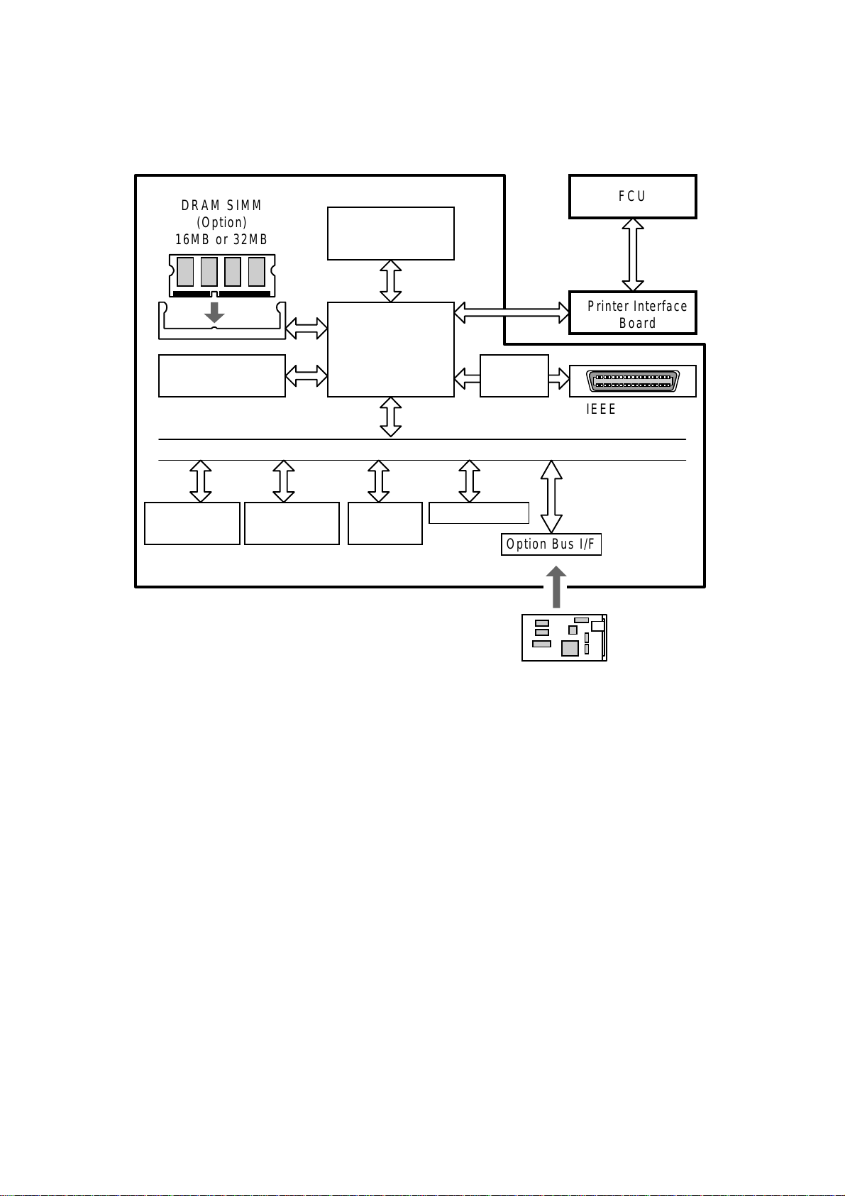
1.3 BLOCK DIAGRAM
DRAM SIMM
(Option)
16MB or 32MB
SDRAM
(8MB)
Code ROM
(4MB Flash)
Font ROM
(1MB Mask)
Controller
CPU
NEC VR4310
133MHz
ASIC
Rocky-W
DATA/ADDRESS BUS
EEPROM
(8kB)
Option Bus I/F
Parallel I/F
Controller
FCU
Printer Interface
Board
IEEE1284 Port
(ECP)
Option Bus I/F
Ethernet NIB
(Option)
10BaseT/100BaseTX
H144V502.WMF
The controller board contains a CPU (NEC VR4310) and an ASIC (Rocky-W). The
ASIC controls the main memory (SDRAM), engine interface, ROM interface,
IEEE1284 parallel interface, and an option bus interface for the NIB. The othe r
option bus interface can be used for upgrading firmware (using an IC card with an
IC card adapter).
There is one optional memory socket that can have either a 16MB or a 32MB
SIMM module to increase RAM capacity. With the 32MB SIMM module, the RAM
capacity is increased to 40MB.
The flash memory card interface allows the firmware for the controller and NIB to
be updated.
The Printer Interface Board (PIF) exchanges video data and operation panel data
(LCD, LED, and key data) between the FCU board and the controller board.
1-4
29 November, 1999 DETAILED SECTION DESCRIPTIONS
2. DETAILED SECTION DESCRIPTIONS
2.1 CONTROLLER FUNCTIONS
2.1.1 IMAGE DATA PROCESSIING
Edge smoothing and toner saving are performed by an ASIC (ROCKY W). The
edge smoothing and toner saving modes can be switched on/off with the machine’s
control panel or the printer driver.
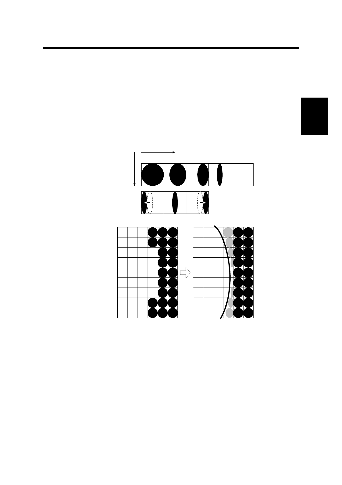
Edge Smoothing
Main Scan Direction
4/4 3/4 2/4 1/4 0
Sub Scan
Fig. A
Direction
Detailed
Descriptions
Fig. B
Fig. C
H144D600.WMF
Jagged edges on characters as shown in the above illustration are reduced using
edge smoothing. Edge smoothing changes the laser pulse duration and position for
certain pixels.
Fig. A shows the four possible pulse durations, and Fig. B shows how the laser
pulse can be in one of three positions within the pixel. Fig. C shows an example of
how edge smoothing is used.
2-1

CONTROLLER FUNCTIONS 29 November, 1999
Toner Saving Mode
Toner saving is done by reducing the number of black dots in the printed image. An
8 x 8 matrix filter is used.
As a result, less toner is used to create the latent image on the drum and black
areas print as gray.
The printer driver prevents edge smoothing and toner saving mode from being
used at the same time.
2.1.2 PAPER SIZE/TYPE DETECTION AND SELECTION
The controller uses the paper sizes detected by the print engine for trays 1, 2, and
3. For the by-pass tray, the user has to specify a paper size using the Job Control
menu in the Printer User Tools. Refer to section 1.1.2 for details on supported
paper sizes.
Thick paper can be selected using User Tools (User Tools – Printer – Job Control
Menu).
When the printer controller receives a print job, the controller prints using the paper
size specified in the PJL or PCL commands and the paper type specified in the
PCL commands.
2-2
29 November, 1999 DETAILED SECTION DESCRIPTIONS
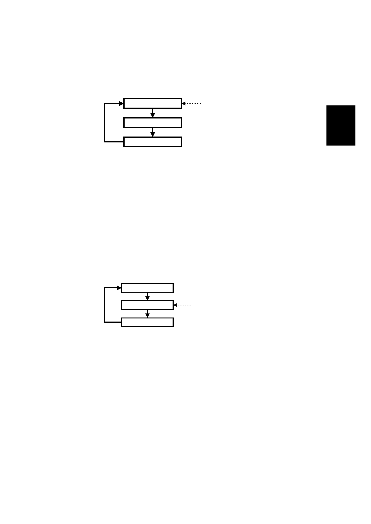
2.1.3 PAPER SOURCE SELECTION
Auto Tray Select
Tray 1
Tray 2 (optional)
Tray 3 (optional)
Start of Tray Search
H144D601.WMF
The controller searches for the specified paper size and paper type, starting from
Tray 1, and uses the first tray that has the specified paper size and paper type. If
the selected tray is pulled out or paper runs out during printing, the controller
searches for another tray with the specific paper size and paper type then if found,
automatically switches to it. If the controller cannot find another paper tray with the
specified paper size and paper type, printing stops and the LCD displays the
message “Load Tray xx [paper size]”.
Manual Tray Select
Detailed
Descriptions
Tray 1
Tray 2 (optional)
Tray 3 (optional)
Start of Tray Search
(Tray selected by the driver)
H144D602.WMF
When the prin ter driver specifies a tray, the selected tray becomes the first tray
checked at the start of the tray search. If the selected tray does not have the size
and type of paper specified by the driver, the controller searches the other trays for
the same paper size and paper type.
NOTE:
Tray Priority in the Job Control menu does not specify the start of the tray
search, but specifies the paper size in the selected tray as the default
paper size.
Tray Lock
If Tray Lock is enabled for a tray, the controller does not use the “locked” tray in the
tray search process. If a tray has, for example, coloured A4 size paper for fax
prints, enable tray lo ck for that tray so that the controller does not select the tray for
printing.
2-3

CONTROLLER FUNCTIONS 29 November, 1999
If the printer driver selects a “locked” tray, the controller uses the tray for printing
only when the specified paper size matches the actual paper size in the tray.
By-pass Tray
The by-pass tray is not part of the automatic tray search. To print from the by-pass
tray, the user has to select the by-pass tray (using either the driver or operation
panel). Even if the by-pass tray is empty, the controller will not switch to another
tray; the message on the LCD asks the user to add paper to the by-pass tray.
Paper Size Mismatch
When the controller could not find the specified paper size and paper type in any of
the trays, the machine displays an error message.
Then the user can either load the requested paper size and paper type in a tray or
select another tray, e.g., a tray that contains A4 size paper, by pressing the “Form
Feed” key.
The controller will print the job if the specified paper size and paper type are
detected in a tray, or if the user presses the Enter key after selecting a tray.
2.1.4 RESET OPERATIONS
Job Reset
This resets the job being processed and ignores all incoming data until a data end
is received.
System Reset
This initializes the fonts and macros downloaded to the RAM. The menu settings,
NIB settings, system log data, and error codes remain unchanged.
NOTE:
Do not use this when the controller is receiving a print job.
Menu Reset
This resets all the menu settings to their default values, including the NIB settings.
2.1.5 ENERGY SAVER MODE
Energy Saver appears in the printer user tool menu, but the setting has no effect.
To select an Energy Saver mode, use the fax user tools.
If the paper size and the dial setting is changed when the machine is in energy
saver mode, the fax machine will not inform this chan ge to the printer controller.
Then a printing error may occur. This error will then wake up the fax machine, and
2-4

29 November, 1999 DETAILED SECTION DESCRIPTIONS
the new paper settings will be informed to the controller immediately, and the user
can try again.
When the machine is in (or recovering from) energy saver mode, the machine
always prints a white page if you print out a service report (such as the print log
sheet). At the second time, the machine prints a normal page. This is because the
fusing unit has not warm ed up enough for printing, but the printer controller cannot
wait for printing while in service mode.
When the machine is in Night Timer mode, the mac hine cannot prin t any data.
Detailed
Descriptions
2-5
29 November, 1999 PRINTER CONTROLLER
3. INSTALLATION PROCEDURES
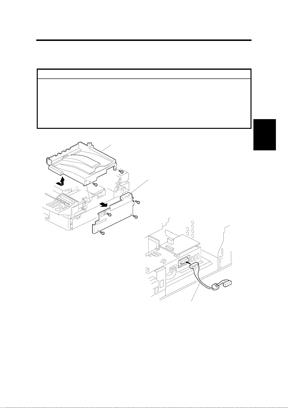
3.1 PRINTER CONTROLLER
CAUTION
ø
Before installing this option, do the following:
1. Print out all messages stored in the memory.
2. Print out the list of user-programmed items and the system parameter
list
3. Turn off the main switch and disconnect the power cord, the telephone
line, and the network cable.
[A]
H144I601.WMF
Installation
[B]
[C]
1. Remove the top cover [A] (2 screws) and right cover [B] (4 screws).
2. Connect cable [C] to the FCU board as shown.
3-1
H144I602.WMF

PRINTER CONTROLLER 29 November, 1999
[C]
[D]
[E]
H144I603.WMF
[G]
[F]
H144I604.WMF
[H]
[B]
H144I605.WMF
3. Attach the printer interf ace [D] to the machine (5 screws) and connect cable [C]
to the printer interface. Then run the cable [C] through the clamp [E] as shown.
NOTE:
Make sure that the cable is not pinched between the printer interface
[D] and the machine.
4. Attach the grounding plates [F] (5 screws) and [G] (2 screws) to the printer
interface unit as shown.
5. Remove the small cover [H] (1 screw) then replace the right cover [B] as shown.
3-2

29 November, 1999 PRINTER CONTROLLER
[L]
[J]
[I]
H144I606.WMF
H144I607.WMF
[K]
H144I608.WMF
6. Open the left cover [I]. Remove the 2 screws to separate the small cover from
the left cover.
Installation
7. Attach the guide plate [J] to the left small cover [K] separated in step 6, as
shown.
8. Attach cushions [L] to the left side of the machine.
3-3
PRINTER CONTROLLER 29 November, 1999
[M]
[N]
[O]
H144I611.WMF
[Q]
[P]
H144I609.WMF
H144I610.WMF
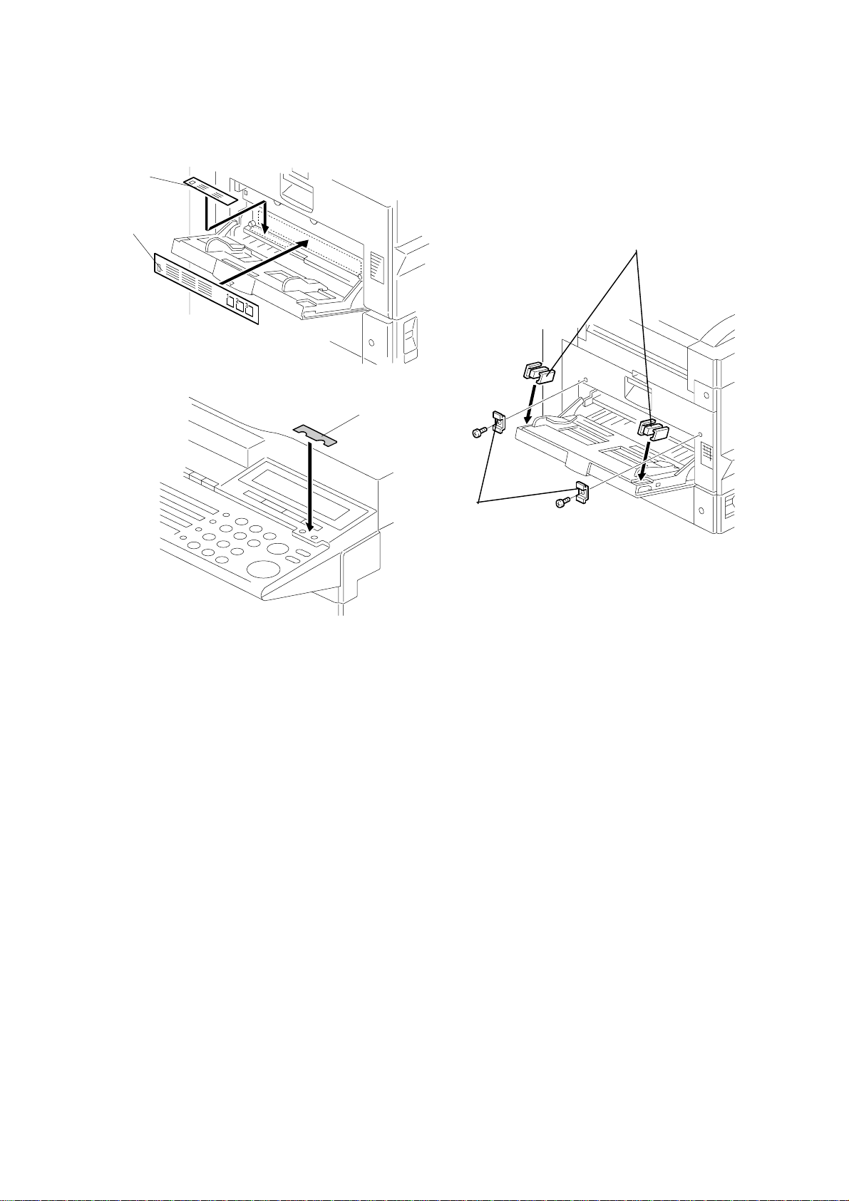
9. Attach the decals [M] and [N] to the left side of the machine.
10. Attach magnet catches [O] to the left cover and small brackets [P] (1 screw
each) to the left side of the machine as shown.
11. Replace the top cover.
12. Attach the decal [Q] to the operation panel as shown.
13. Plug in the machine and make sure that the parallel cable is not connected to
the controller, then turn the machine on.
14. Enter the printer service mode (î – [Printer] – ú + ë) and change the
Product Name to “ ”(blank). Then press the } key.
15. Print the Print Log page to check that the printer controller is connected
correctly. Then exit service mode (ú + ó).
16. Enter the service mode and print the system parameter list, then make sure that
“PRINTER INTERFACE” is listed as an option. Then exit the service mode.
17. If the parallel cable is going to be connected, turn off the machine first, connect
the parallel cable, and then turn the machine back on again.
3-4
29 November, 1999 NETWORK INTERFACE BOARD (NIB)
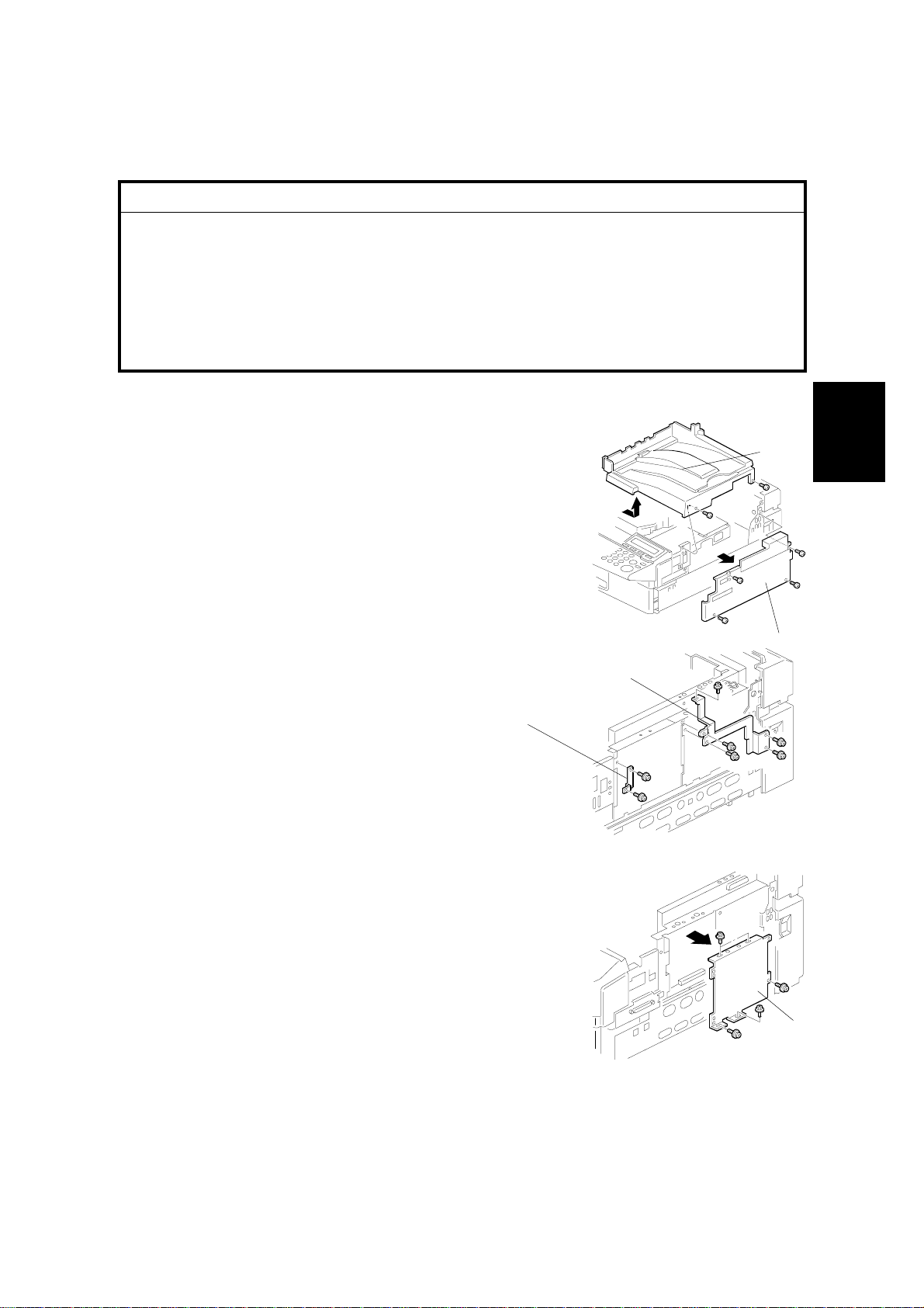
3.2 NETWORK INTERFACE BOARD (NIB)
CAUTION
ø
Before installing this option, do the following:
1. Print out all messages stored in the memory.
2. Print out the list of user-programmed items and the system parameter
list
3. Turn off the main switch and disconnect the power cord, the telephone
line, and the network cable.
1. Remove the top cover [A] (2 screws) and right cover
[B] (4 screws).
[A]
Installation
2. Remove the grounding plates [C] (5 screws) and [D]
(2 screws).
[D]
3. Remove the printer interface left plate [E] (5
screws).
G919I501.WMF
[C]
G919I503.WMF
[B]
G919I502.WMF
[E]
3-5
 Loading...