

Ricoh Toscana-P1 J007, Piemonte-P1N J011, Toscana-P1N J010, Toscana-P1, Toscana-P1N Service Manual
...
Toscana-P1/Toscana-P1N/Piemonte-P1N
Machine Code: J007/J010/J011
SERVICE MANUAL
Mar. 1st , 2006
Subject to change
Safety Instructions
For your safety, please read this manual carefully before you service machine. Always keep this manual
handy for future reference.
Safety Information
Always obey the these safety precautions when using this product.
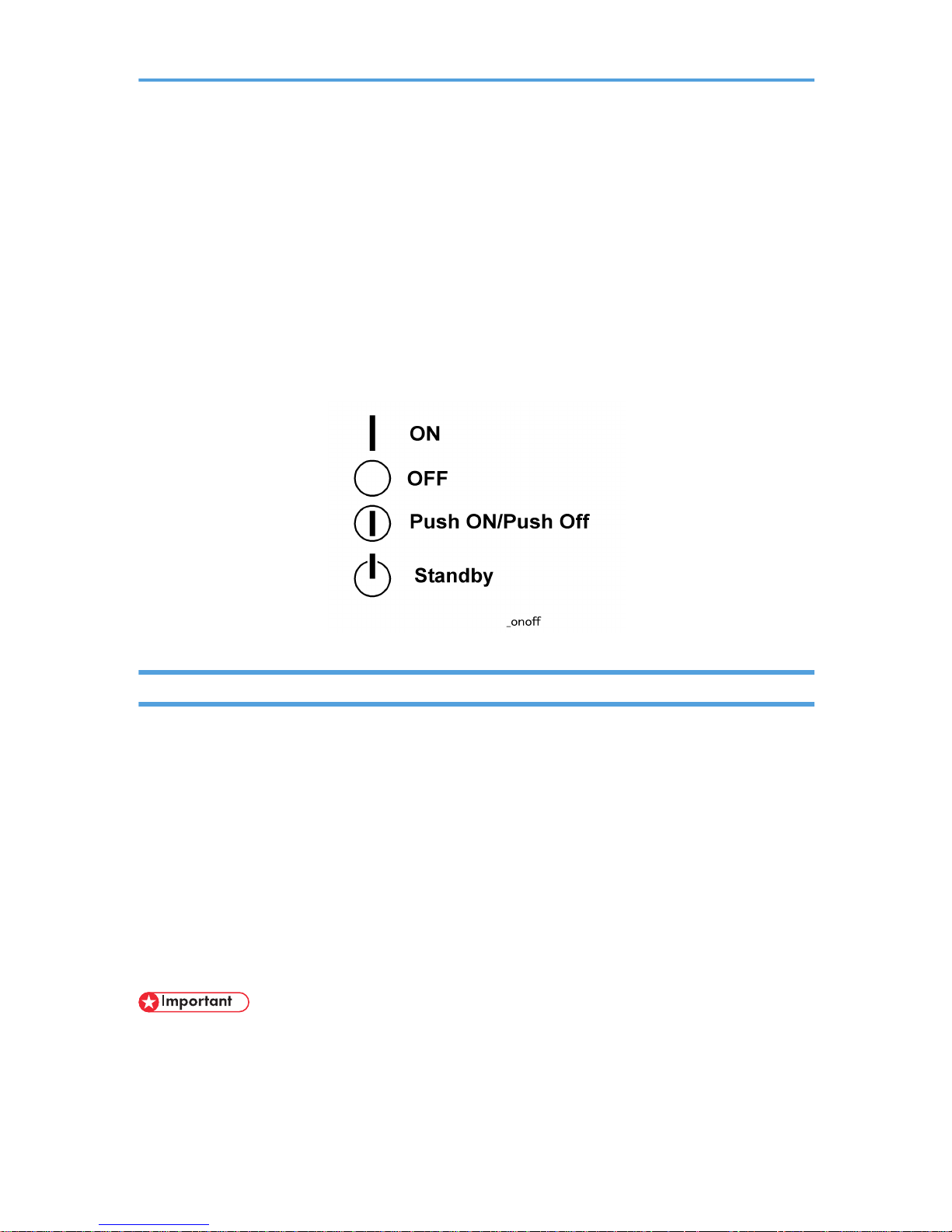
Switches and Symbols
Where symbols are used on or near switches on machines for Europe and other areas, the meaning of
each symbol conforms with IEC60417.
Responsibilities of the Customer Engineer
Maintenance
Maintenance shall be done only by trained customer engineers who have completed service training for
the machine and all optional devices designed for use with the machine.
Installation
The main machine and options can be installed by either the customer or customer engineer. The customer
or customer engineer must follow the installation instructions described in the operating instructions.
Reference Material for Maintenance
Maintenance shall be done with the special tools and the procedures prescribed for maintenance of the
machine described in the reference materials (service manuals, technical bulletins, operating instructions,
and safety guidelines for customer engineers).
• Use only consumable supplies and replacement parts designed for use with the machine.
1

Before Installation, Maintenance
Shipping and Moving the Machine
• Work carefully when lifting or moving the machine. If the machine is heavy, two or more customer
engineers may be required to prevent injuries (muscle strains, spinal injuries, etc.) or damage to the
machine if it is dropped or tipped over.
• Personnel moving or working around the machine should always wear proper clothing and footwear.
Never wear loose fitting clothing or accessories (neckties, loose sweaters, bracelets, etc.) or casual
footwear (slippers, sandals, etc.) when lifting or moving the machine.
• Always unplug the power cord from the power source before you move the machine. Before you
move the machine, arrange the power cord so it will not fall under the machine.
Power
• Always turn the machine off and disconnect the power plug before doing any maintenance procedure.
After turning the machine off, power is still supplied to the main machine and other devices. To prevent
electrical shock, switch the machine off, wait for a few seconds, then unplug the machine from the
power source.
• Before you do any checks or adjustments after turning the machine off, work carefully to avoid injury.
After removing covers or opening the machine to do checks or adjustments, avoid touching electrical
components or moving parts (gears, timing belts, etc.).
• After turning the machine on with any cover removed, keep your hands away from electrical components and moving parts. Never touch the cover of the fusing unit, gears, timing belts, etc.
Installation, Disassembly, and Adjustments
• After installation, maintenance, or adjustment, always check the operation of the machine to make
sure that it is operating normally. This ensures that all shipping materials, protective materials, wires
and tags, metal brackets, etc., (attached to protect the machine during shipping), have been removed
and that no tools remain inside the machine.
• Never use your fingers to check moving parts that are causing spurious noise. Never use your fingers
to lubricate moving parts while the machine is operating.
2

Special Tools
• Use only standard tools approved for machine maintenance.
• For special adjustments, use only the special tools and lubricants described in the service manual.
Using tools incorrectly, or using tools that could damage parts, could damage the machine or cause
injuries.
During Maintenance
General
• Before you begin a maintenance procedure always switch the machine off.
• Disconnect the power plug from the power source.
• Allow the machine to cool for at least 10 minutes.
• Avoid touching the components inside the machine that are labeled as hot surfaces.
Safety Devices
• Never remove any safety device (a fuse, thermistor, etc.) unless it requires replacement. Always
replace a safety device immediately.
• Never do any procedure that defeats the function of any safety device. Modification or removal of a
safety device (fuse, thermistor, etc.) could cause a fire and personal injury. After removal and replacement of any safety device, always test the operation of the machine to ensure that it is operating
normally and safely.
• For replacement parts use only the correct fuses, thermistors, circuit breakers, etc. rated for use with
the machine. Using replacement devices not designed for use with the machine could cause a fire
and personal injuries.
Organic Cleaners
• During preventive maintenance, never use any organic cleaners (alcohol, etc.) other than those described in the service manual. (Refer the “2. Preventive Maintenance” in the Service Manual.)
• Make sure the room is well ventilated before using any organic cleaner. Always use organic solvents
in small amounts to avoid breathing the fumes and becoming nauseous.
3

• Switch the machine off, unplug it, and allow it to cool before doing preventive maintenance. To avoid
fire or explosion, never use an organic cleaner near any component that generates heat.
• Wash your hands thoroughly after cleaning parts with an organic cleaner to avoid contamination of
food, drinks, etc. which could cause illness.
Power Plug and Power Cord
• Before servicing the machine (especially when responding to a service call), always make sure that
the power plug has been inserted completely into the power source. A partially inserted plug could
lead to heat generation (due to a power surge caused by high resistance) and cause a fire or other
problems.
• Always check the power plug and make sure that it is free of dust and lint. Clean it if necessary. A
dirty plug can generate heat and cause a fire.
• Inspect the entire length of the power cord for cuts or other damage. Replace the power cord if
necessary. A frayed or otherwise damaged power cord can cause a short circuit which could lead
to a fire or personal injury from electrical shock.
• Check the length of the power cord between the machine and power supply. Make sure the power
cord is not coiled or wrapped around any object such as a table leg. Coiling the power cord can
cause excessive heat to build up and could cause a fire.
• Make sure that the area around the power source is free of obstacles so the power cord can be
removed quickly in case of an emergency.
• Make sure that the power cord is grounded (earthed) at the power source with the ground wire on
the plug.
• Connect the power cord directly into the power source. Never use an extension cord.
• When you disconnect the power plug from the power source, always pull the plug, not the cable.
After Installation Servicing
Disposal of Used Items
• Ink is flammable. Never attempt to incinerate empty ink cartridges.
• Always dispose of used items in accordance with the local laws and regulations regarding the disposal
of such items.
4

• To protect the environment, never dispose of this product or any kind of waste from consumables at
a household waste collection point. Dispose of these items at one of our dealers or at an authorized
collection site.
Points to Confirm with Operators
At the end of installation or a service call, instruct the user about use of the machine. Emphasize the following
points.
• Show operators how to remove jammed paper and troubleshoot other minor problems by following
the procedures described in the operating instructions.
• Point out the parts inside the machine that they should never touch or attempt to remove.
• Confirm that operators know how to store and dispose of consumables such as ink cartridges, ammonia water, paper, etc..
• Make sure that all operators have access to an operating instruction manual for the machine.
• Confirm that operators have read and understand all the safety instructions described in the operating
instructions.
• Demonstrate how to turn off the power and disconnect the power plug (by pulling the plug, not the
cord) if any of the following events occur:
1. Something has spilled into the product.
2. Service or repair of the product is necessary.
3. The product cover has been damaged.
• Caution operators about removing paper fasteners around the machine. They should never allow
paper clips, staples, or any other small metallic objects to fall into the product.
• Make sure the operators understand the following points:
• The operator must lift the output tray to release the paper cassette before loading paper.
• Paper is loaded in the standard paper cassette without removing it from the printer.
• The operator should never attempt to remove the paper cassette from the printer.
Special Safety Instructions For Ink Cartridges
Accidental Exposure To Ink
• If ink gets on the skin, wash the affected area immediately with soap and cold running water.
5

• If ink gets into the eyes, immediately flush the eyes with cold running water. If there are signs of irritation
or other problems, seek medical attention.
• If ink is swallowed, drink a strong solution of cold water and table salt to induce vomiting. Seek medical
attention immediately.
• Ink is difficult to remove from fabric. Work carefully to avoid staining clothing when performing routine
maintenance or replacing cartridges.
Handling and Storing Ink Cartridges
• Ink is flammable. Never store ink cartridges in a location where they will be exposed to high temperature or an open flame.
• Always store ink cartridges out of the reach of children.
• Always store ink cartridges in a cool, dry location that is not exposed to direct sunlight.
Ink Cartridge Disposal
• Attach the caps to empty ink containers for temporary storage to avoid accidental spillage.
• Return empty ink cartridges to a local dealer who can accept such items for collection and recycling
or disposal.
• If the customer decides to dispose of empty ink cartridges, make sure that they are disposed of in
accordance with local laws and regulations.
6
Conventions Used in this Manual
Symbols and Abbreviations
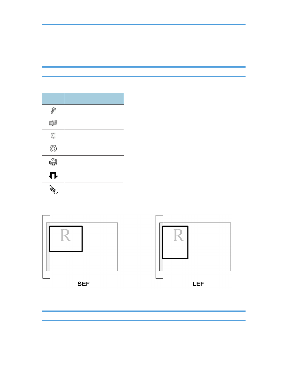
This manual uses several symbols.
Symbol What It Means
Screw
Connector
E-ring
Clip ring
Clamp
Pawls (sensors)
Spring
This manual uses the following abbreviations.
Throughout this service manual, "SEF" denotes "Short Edge Feed" and "LEF" denotes "Long Edge Feed".
Warnings, Cautions, Notes
In this manual, the following important symbols and notations are used.
7

• A Warning indicates a potentially hazardous situation. Failure to obey a Warning could result in
death or serious injury.
• A Caution indicates a potentially hazardous situation. Failure to obey a Caution could result in minor
or moderate injury or damage to the machine or other property.
• Obey these guidelines to avoid problems such as misfeeds, damage to originals, loss of valuable
data and to prevent damage to the machine
• This information provides tips and advice about how to best service the machine.
Trademarks
• Microsoft®, Windows®, and MS-DOS® are registered trademarks of Microsoft Corporation in the
United States and /or other countries.
• PostScript® is a registered trademark of Adobe Systems, Incorporated.
• PCL® is a registered trademark of Hewlett-Packard Company.
• Ethernet® is a registered trademark of Xerox Corporation.
• PowerPC® is a registered trademark of International Business Machines Corporation.
• Other product names used herein are for identification purposes only and may be trademarks of their
respective companies. We disclaim any and all rights involved with those marks.
8

TABLE OF CONTENTS
Safety Instructions...............................................................................................................................................1
Responsibilities of the Customer Engineer....................................................................................................1
Before Installation, Maintenance..................................................................................................................2
During Maintenance......................................................................................................................................3
After Installation Servicing.............................................................................................................................4
Special Safety Instructions For Ink Cartridges..............................................................................................5
Conventions Used in this Manual......................................................................................................................7
Symbols and Abbreviations...........................................................................................................................7
Warnings, Cautions, Notes...........................................................................................................................7
Trademarks.....................................................................................................................................................8
1. Installation
Preparation.......................................................................................................................................................17
Environment..................................................................................................................................................17
Choosing a Location....................................................................................................................................17
Minimum Space Requirements...................................................................................................................19
Power Source...............................................................................................................................................19
Using the Operation Panel..............................................................................................................................20
Here is a brief description of how to use the keys on the printer operation panel.................................20
Here are some more details about how to use these keys.......................................................................21
Installation Procedure......................................................................................................................................24
Accessory Check..........................................................................................................................................24
Remove the Shipping Material...................................................................................................................25
Carrying the Printer......................................................................................................................................26
Install the Print Cartridges............................................................................................................................26
Load Paper...................................................................................................................................................28
Connect the Power Cord.............................................................................................................................31
Do the USB Connection...............................................................................................................................33
Clean the Print Heads and Do a Test Print.................................................................................................34
Options.............................................................................................................................................................35
Network Interface Board J508...................................................................................................................35
Multi Bypass Tray J507...............................................................................................................................36
Paper Feed Unit...........................................................................................................................................37
Important Information......................................................................................................................................41
9

Checklist Before Moving the Printer...........................................................................................................41
If the Printer Is Not Used Frequently…........................................................................................................41
2. Preventive Maintenance
PM Table...........................................................................................................................................................43
3. Replacement and Adjustment
Removals...........................................................................................................................................................45
Maintainable Items......................................................................................................................................45
Before You Begin.........................................................................................................................................47
Easy Removals..................................................................................................................................................50
Top Cover (J011)........................................................................................................................................50
Output Tray, Paper Feed Cassette.............................................................................................................51
NIB Cover, NIB............................................................................................................................................51
Duplex Unit, Rear Plate...............................................................................................................................52
Ink Collection Tank......................................................................................................................................52
Removing the Covers.......................................................................................................................................54
Right Cover...................................................................................................................................................54
Top Cover (J007/J010).............................................................................................................................55
Crosspiece (J011).......................................................................................................................................55
Rear Cover...................................................................................................................................................56
Right Front Door...........................................................................................................................................57
Right Front Cover, Operation Panel...........................................................................................................57
Front Cover...................................................................................................................................................60
Left Front Cover............................................................................................................................................60
Left Cover......................................................................................................................................................61
Component Removal.......................................................................................................................................63
Flushing Unit.................................................................................................................................................63
Maintenance Unit........................................................................................................................................64
PSU................................................................................................................................................................66
High Voltage Power supply Board.............................................................................................................67
.Main Control Board...................................................................................................................................67
Horizontal Motor.........................................................................................................................................72
Vertical Motor..............................................................................................................................................73
Vertical Encoder Sensor..............................................................................................................................75
10

Vertical Encoder Wheel..............................................................................................................................75
Cooling Fan..................................................................................................................................................77
Duplexer Detection Board...........................................................................................................................78
Carriage Position Sensor.............................................................................................................................78
Air Release Solenoid...................................................................................................................................79
Ink Level Sensor............................................................................................................................................80
2nd Registration Sensor..............................................................................................................................81
Cleaning Procedures........................................................................................................................................82
Service Call Procedures..............................................................................................................................82
Service Technician Responsibility...............................................................................................................82
Flushing Gate Cleaning...............................................................................................................................83
Maintenance Unit Cleaning........................................................................................................................83
Print Head Cleaning....................................................................................................................................85
Feed Roller Cleaning...................................................................................................................................85
Transport Belt Cleaning...............................................................................................................................86
4. Troubleshooting
Printer Display Summary..................................................................................................................................87
Operation Panel Display.............................................................................................................................87
Display Menu Summary..............................................................................................................................88
Operation Panel Status and Error Messages............................................................................................90
Status Monitor Messages............................................................................................................................93
Self-Diagnostic Test Flow.................................................................................................................................96
SC Error Codes................................................................................................................................................99
Summary of Error Levels..............................................................................................................................99
Out-of-Range Temperature Errors..............................................................................................................99
SC Code Tables........................................................................................................................................100
General Troubleshooting..............................................................................................................................104
Poor Quality Image...................................................................................................................................104
Paper Misfeed...........................................................................................................................................109
Poor Printer Performance (Miscellaneous)..............................................................................................113
Unusual Noises..........................................................................................................................................114
Image Correction...........................................................................................................................................115
Preparing for Test Printing.........................................................................................................................115
11

Adjust Paper Feed.....................................................................................................................................115
Nozzle Blockage Check...........................................................................................................................116
Print head Cleaning and Flushing............................................................................................................117
Adjust Print head Position..........................................................................................................................117
Registration................................................................................................................................................118
Drive Cleaning...........................................................................................................................................119
Cleaning the Print heads Before Long Term Storage..............................................................................121
Transport Belt Charge Adjustments..............................................................................................................123
The Charge Area.......................................................................................................................................124
Print Mode Table.......................................................................................................................................126
Temperature/Humidity Table...................................................................................................................127
Charge Pitch Table....................................................................................................................................133
Checking Charge Pitch Applied for the Print Mode ..............................................................................139
5. Service Tables
Before You Begin...........................................................................................................................................141
Entering/Exiting SP Mode........................................................................................................................141
Using the SP Menus...................................................................................................................................141
SP Tables........................................................................................................................................................143
SP Table Key..............................................................................................................................................143
Group 1000..............................................................................................................................................144
Goup 2000...............................................................................................................................................162
Group 3000..............................................................................................................................................165
Group 4000..............................................................................................................................................167
Group 5000..............................................................................................................................................167
Group 6000..............................................................................................................................................173
Group 7000..............................................................................................................................................173
Bit Switches.....................................................................................................................................................187
Changing Bit Switch Settings....................................................................................................................187
Bit Switch Summary...................................................................................................................................187
Status Reports.................................................................................................................................................192
System Summary.......................................................................................................................................192
Service Summary.......................................................................................................................................193
Engine Summary Chart.............................................................................................................................193
12

6. Detailed Section Descriptions
Important Parts...............................................................................................................................................195
Front View..................................................................................................................................................195
Rear View...................................................................................................................................................196
Electrical Components...................................................................................................................................198
Overview....................................................................................................................................................198
Carriage Unit.................................................................................................................................................200
Overview....................................................................................................................................................200
Print Head..................................................................................................................................................200
Print Head Tank.........................................................................................................................................201
Ink Ejection Device....................................................................................................................................202
Ink Near End..............................................................................................................................................203
Ink Out........................................................................................................................................................204
Registration Sensors..................................................................................................................................205
Ink Supply System..........................................................................................................................................207
Overview....................................................................................................................................................207
Ink cartridges.............................................................................................................................................208
Ink Cartridge Set Sensors.........................................................................................................................210
Ink Pumps...................................................................................................................................................211
Print Heads.................................................................................................................................................212
Print Head Maintenance...........................................................................................................................215
Maintenance Unit......................................................................................................................................216
Ink Collection Tank....................................................................................................................................219
Ink Collection Ink level sensor..................................................................................................................220
Flushing Unit...............................................................................................................................................221
Carriage Drive...............................................................................................................................................223
Overview....................................................................................................................................................223
Envelope Selector......................................................................................................................................224
Paper Feed, Transport, Output.....................................................................................................................226
Overview....................................................................................................................................................226
Cassette Lock/Release.............................................................................................................................226
Leading Edge and Paper Size Detection.................................................................................................227
Paper Jam, Trailing Edge Detection.........................................................................................................228
13

Paper Transport Drive...............................................................................................................................228
Paper Path..................................................................................................................................................229
Transport Belt.............................................................................................................................................230
Charge Leak Detection.............................................................................................................................231
Cooling Fan...............................................................................................................................................232
Top Cover Switch......................................................................................................................................232
Electrical Component Functions....................................................................................................................233
Main Boards..............................................................................................................................................233
Control Board............................................................................................................................................234
CCB............................................................................................................................................................235
DIB..............................................................................................................................................................236
HRB.............................................................................................................................................................237
OPU............................................................................................................................................................238
HVPS...........................................................................................................................................................239
PSU.............................................................................................................................................................240
Electrical Component Summary...............................................................................................................240
Basic Operation.............................................................................................................................................247
Initialization Sequence at Power On.......................................................................................................247
Image Processing...........................................................................................................................................248
Duplex Unit.....................................................................................................................................................249
Overview....................................................................................................................................................249
Duplex Drive..............................................................................................................................................249
Duplexer Cover Switch.............................................................................................................................250
Duplexer Set Switch..................................................................................................................................251
Bypass (Option).........................................................................................................................................252
Paper Feed Unit J506 (Tray 2).....................................................................................................................254
Overview....................................................................................................................................................254
Paper Feed.................................................................................................................................................255
7. Specifications
Specifications.................................................................................................................................................257
Printer Engine Base Specifications...........................................................................................................257
Paper Trays................................................................................................................................................261
Supported Paper Sizes.............................................................................................................................263
14

Printer Interface, Operating Systems.......................................................................................................266
External Options........................................................................................................................................266
Consumables J007/J010, J011 ............................................................................................................266
15

16
1. Installation
Preparation
Environment
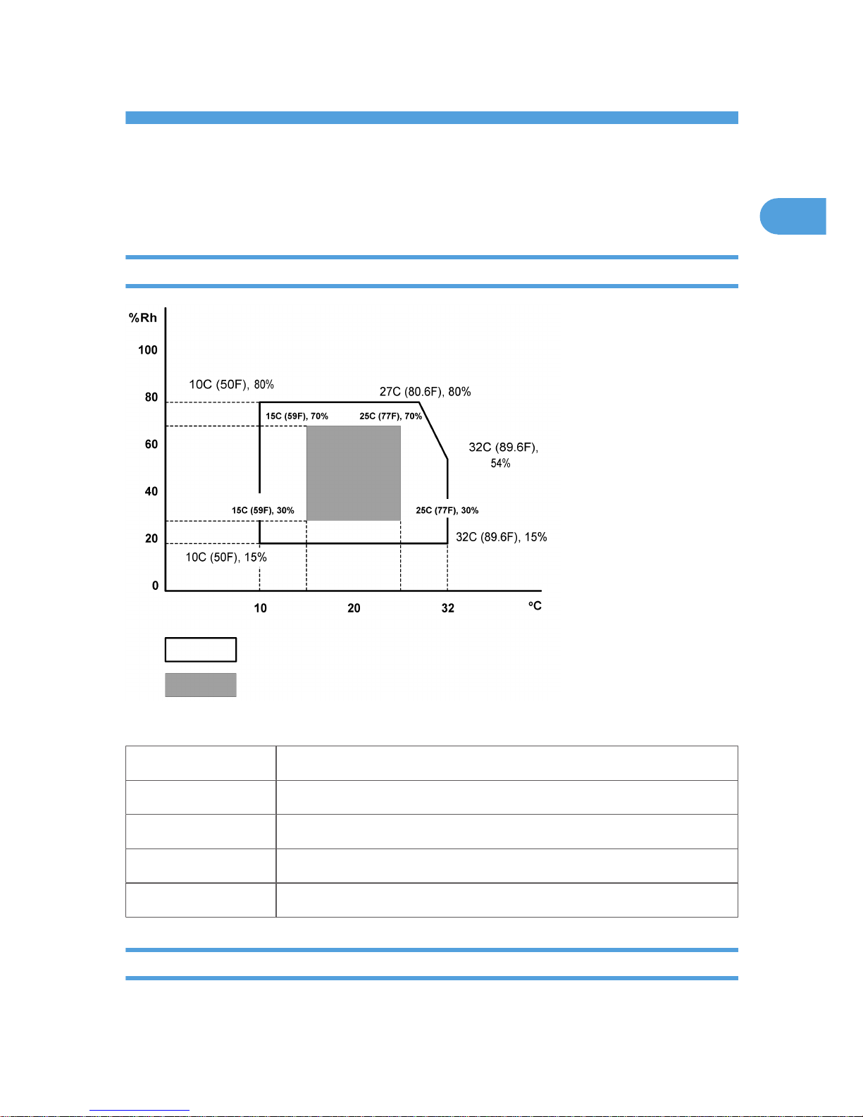
Set up the machine in a location that meets these minimum requirements:
Temperature Range: 10°C to 32°C (50°F to 89.6°F)
Humidity Range: 15% to 80% RH
Ambient Illumination: Less than 1,500 Lux (never expose to direct sunlight).
Ventilation: More than 30 m3/hr/person in the work area
Ambient Dust: Less than 0.10 mg/m3
Choosing a Location
1. Always install the machine:
17
1

• On a sturdy, level surface.
• Where it will not become damp.
2. Make sure the machine is never exposed to:
• Extreme changes from low to high temperature or high to low temperature.
• Cold or cool air directly from an air conditioner.
• Heat from a space heater.
3. Never install the machine in areas near:
• Dust, lint, or corrosive fumes.
• Strong vibration.
4. Do not use the machine at any location higher than 2,000 m (6,500 ft) above sea level.
5. Set up and use the machine on a sturdy, level surface.
• Place a carpenter's level on the machine front-to-back, and side-to-side and confirm that it is
level.
• variations between the front/back and left/right level readings should be less than 2 degrees.
Required Software Environment
Software Windows 98, Window Me, Windows 2000, Windows XP, Windows 2003, Window NT
4.0 or later
Hardware 80-100 MB of HDD space available
Limitations
These limitations apply to the use of this printer:
• Ver. 4.0 or later is required for Windows NT.
• Windows NT does not support a USB connection to the printer. Use a network connection.
• The USB connection is supported by Windows 98, Windows Me, Windows 2000, Windows XP,
Windows Server 2000.
• USB connection with Windows 98 and Windows Me is limited to USB 1.1.
1. Installation
18
1
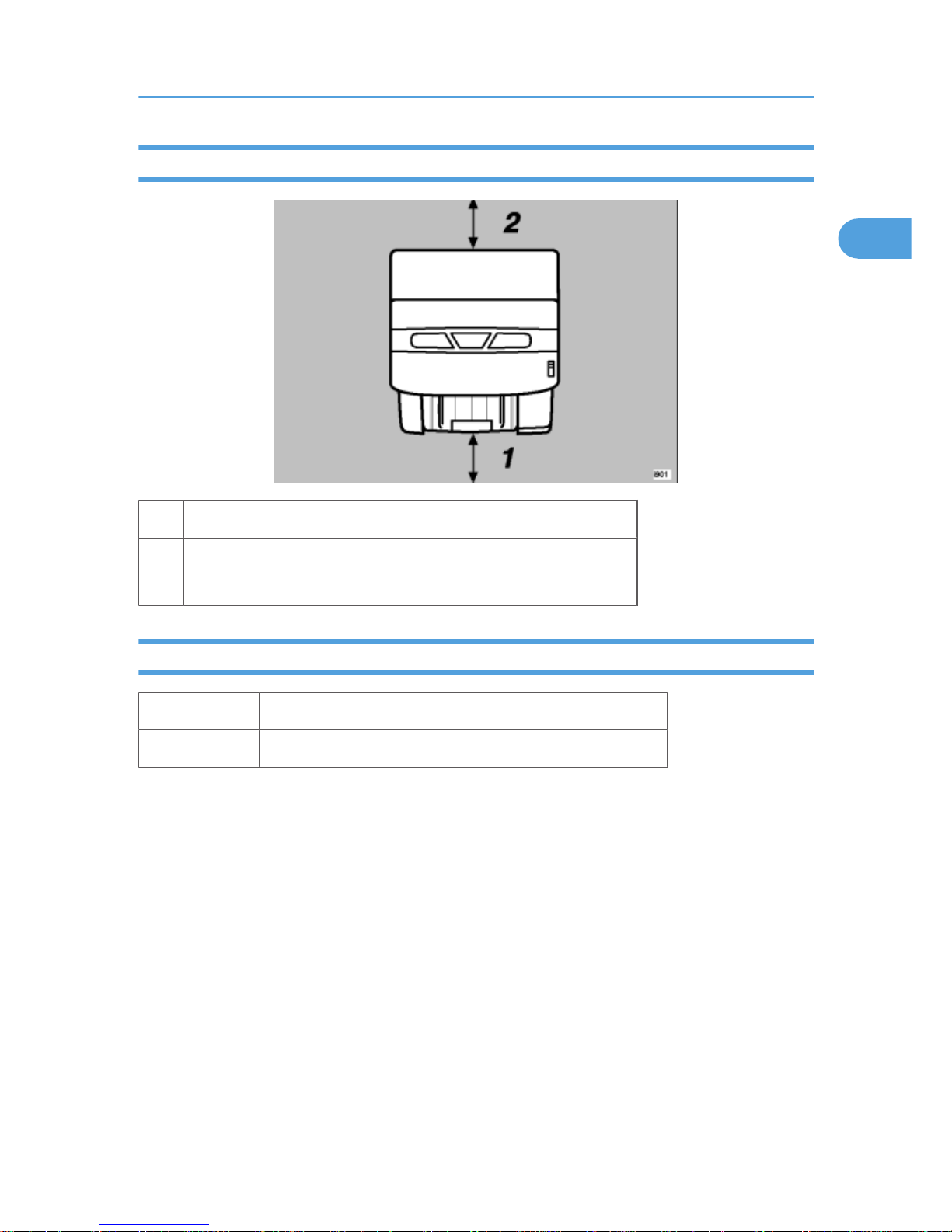
Minimum Space Requirements
1 At least 190 mm (7.5 in.)
2
At least 120 mm (4.7 in.)
At least 350 mm (13.8 in.) with Multi-Bypass Tray B507
Power Source
North America 100-120 V, 50-60 Hz
Europe 220-240V 50-60 Hz
Preparation
19
1
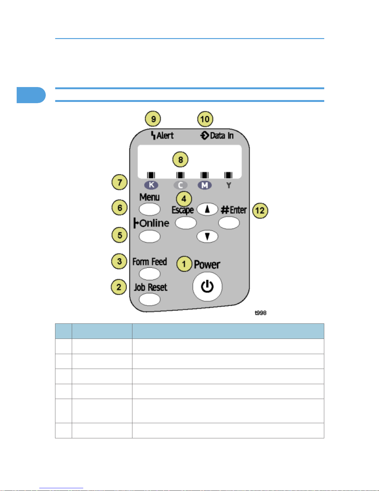
Using the Operation Panel
Here is a brief description of how to use the keys on the printer operation panel.
Key/Indicator What It Does
1 Power Push to turn the printer on/off
2 Job Reset Push to cancel the print job in progress.
3 Form Feed When the printer is offline, push to print all the data in the printer buffer.
4 Escape Push to restore the display to the previous condition.
5 Online Push to toggle the printer between online/offline. When lit the printer is
online, and when off the printer is offline.
6 Menu Push to view the current printer settings.
1. Installation
20
1
Key/Indicator What It Does
7 Cartridge End LEDs Indicate the statuses of the print cartridges.
8 Display Shows the current printer status and error messages.
9 Alert Lights when an error occurs. Red indicates an error that will stop printing.
Yellow indicates and a potential error (follow the instruction that appears
in the display).
10 or Push once to increment the display setting by 1 (up or down). Press and
hold to increment the setting by 10.
11 Data-In Blinks when the printer is receiving data. Lights and stays on when data is
in the printer buffer to be printed.
12 #Enter Push to execute the menu item on the display.
Here are some more details about how to use these keys.
• In the procedures below, "select" means push or on the printer operation panel until you see
the item in the display on the printer operation panel.
To turn the printer on and off
1. To turn the printer on, press and hold the [Power] key for at least 1 sec.
The [Power] key flashes and continues flashing until the printer warms up.
When the printer is ready for operation, the [Power] key lights and remains on. At this time the printer
is in standby mode and ready to print.
2. Press the [Power] key once to turn the printer off. The power LED flashes slowly for a few
moments. Then it goes off.
To print the Config. Page
1. Push [Menu] and select "List/Test Print".
2. Push [#Enter], select "Config. Page" then push [#Enter].
3. Push [Online] to return to standby mode.
Using the Operation Panel
21
1

To clean all the printheads
1. First, clean the print head:
• Push [Menu], select "Maintenance", push #Enter].
• Select "Head-cleaning" and push [#Enter].
• Push [Online] to return to standby mode.
2. If this doe not solve the problem, flush the printhead:
• Push [Menu], select "Maintenance" and push [#Enter].
• Select "Head-flushing" and push [#Enter].
• Push [Online] to return to standby mode.
• These procedures consume ink.
• Flushing consumes more ink than cleaning.
• Flush the print head nozzles only if the cleaning (the first procedure) does not solve the problem.
To print a Nozzle Check Pattern
1. Push [Menu], select "Maintenance", and push [#Enter].
2. Select "Nozzle Check" and push [#Enter]
3. Push [Online] to return to standby mode.
For more about how to use the Nozzle Check pattern to diagnose and correct problems, see Section
"4 Troubleshooting".
To restart an interrupted print job
Press the [Form Feed] key to start a print job again after you remove the cause of an error (paper jam, for
example). The [Job Reset] key flashes or lights and stays in this condition for errors. For more, see Section
“4. Troubleshooting”.
To feed a sheet manually
1. Set a sheet of paper in the bypass tray.
2. Press the [Form Feed] key when the software application prompts you to do so.
1. Installation
22
1

To feed 1 blank sheet (cleaning):
1. Push [Menu], select "Maintenance", and push [#Enter].
2. Select "Paper Feed Test" and push [#Enter]
3. Push [Online] to return to standby mode.
To feed 3 blank sheets (cleaning):
1. Push [Menu], select "Maintenance", and push [#Enter].
2. Select "De-condensation" and push [#Enter]
3. Push [Online] to return to standby mode.
Reading the Cartridge End LEDs
Each LED shows the position of each Print cartridge in the printer:
K (Black), C (Cyan), M (Magenta), and Y (Yellow)
Status What It Means
Flashing
The cartridge is empty. You can use the printer for a short time. Replace the cartridge
as soon as possible.
On There is no ink in the printer. At this time, you cannot print. Replace the ink cartridge.
All On A Print cartridge is not in the machine, or, is not installed correctly. Open the right front
door. Check all the cartridges.
Using the Operation Panel
23
1
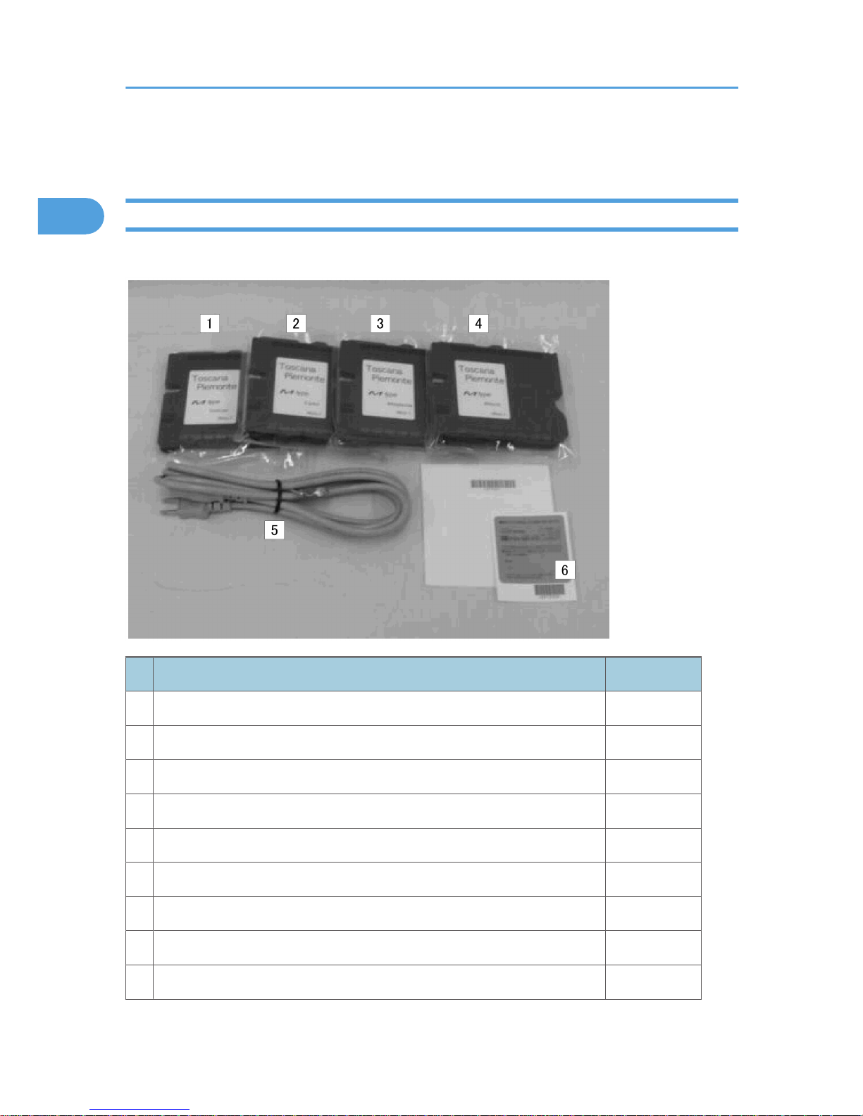
Installation Procedure
Accessory Check
Check the accessories and their quantities against this list:
Description Quantity
1 Starter Cartridge - Yellow 1
2 Starter Cartridge - Magenta 1
3 Starter Cartridge - Cyan 1
4 Starter Cartridge - Black 1
5 Power Cord (EU Model Only)
6 Decals
7 Quick Installation Guide (not shown) 1
8 Setup Handbook (not shown) 1
9 CD-ROM (Printer driver, Utilities, User Guide) (not shown) 1
1. Installation
24
1
• The power cord is attached to the NA model. The power cord is provided as a separate item for the
EU model only.
• A USB cable and LAN cable are not provided and must be purchased separately.
• Before you do any of the procedures in this manual, make sure the printer is turned off and unplugged
from the power source. Do not turn the printer on until you instructed to do so.
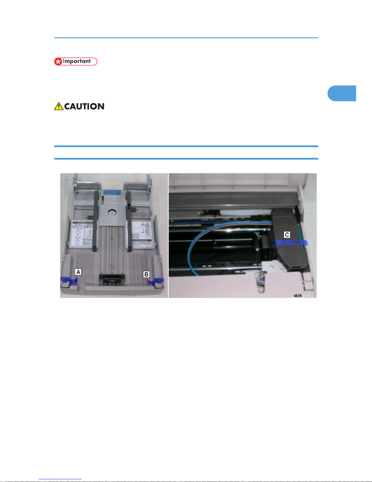
Remove the Shipping Material
1. Remove the plastic shrink-wrap covering the printer.
2. Remove all the other orange tape from the printer body (front, top, back).
3. Pull out the paper cassette and remove the orange tape [A] and [B].
4. Open the top cover and remove the tape from the carriage [C].
Installation Procedure
25
1
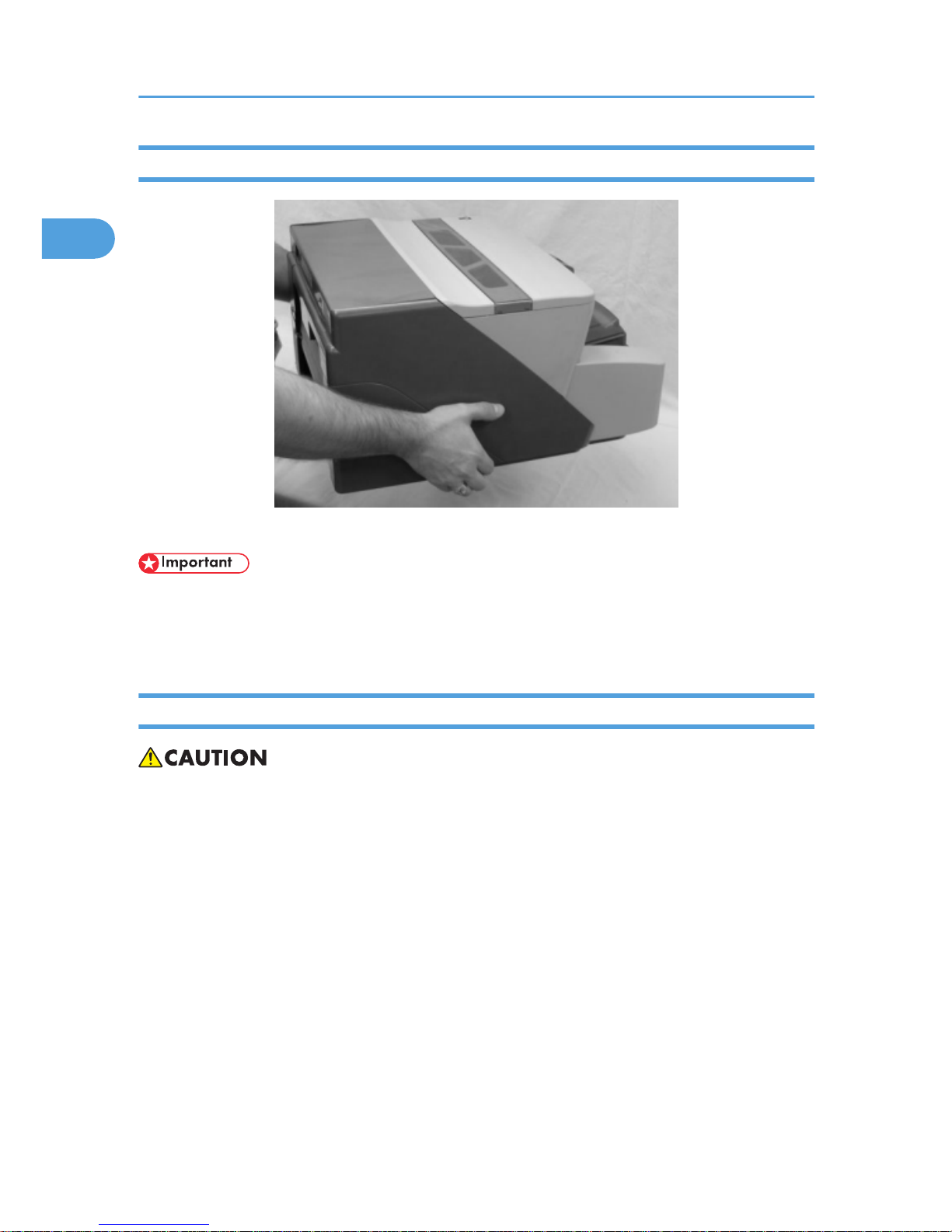
Carrying the Printer
Hold the printer by the grips provided on each side.
• To prevent damage to the printer, always carry the printer as shown above.
• Never lift the printer with your hand under the duplex unit in the back or under the paper cassette in
the front.
Install the Print Cartridges
• If ink gets on the skin, wash the affected area immediately with soap and cold running water.
• If ink gets into the eyes, immediately flush the eyes with cold running water. If there are signs of irritation
or other problems, seek medical attention immediately.
• If ink is swallowed, drink a strong solution of cold water and table salt to induce vomiting. Seek medical
attention immediately.
• Ink is difficult to remove from fabric. Work carefully to avoid staining clothing when performing routine
maintenance or replacing cartridges.
• Always store ink cartridges out of the reach of children.
1. Installation
26
1
1. Unpack the four cartridges provided with the printer.
• The "Starter" ink cartridges provided for installation contain a limited supply of ink. Make sure
that you have and additional set of ink cartridges available for replacement before you use the
printer.
• Use only Ricoh Print Cartridges designed for use with this printer.
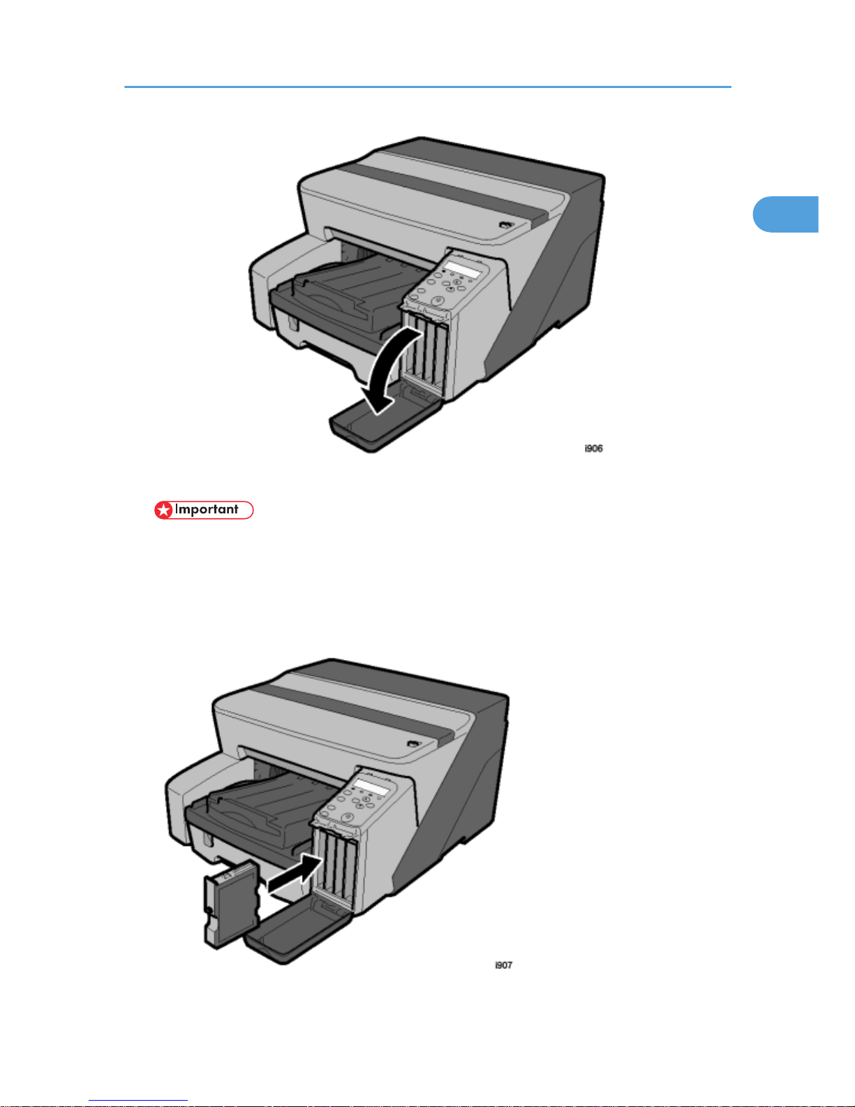
2. Open the right front cover.
3. Remove the Black Print cartridge from its package.
Installation Procedure
27
1
4. Hold the black cartridge as shown.
• Never touch the metal contact plate on the rear side.
• Each cartridge is marked with a color label.
• The Cartridge End LED marks below the display show you the order of insertion from left to right
(K (Black), C (Cyan), M (Magenta), Y (Yellow).
5. Insert the black ink cartridge in the first slot on the left.
6. Press on the area marked "PUSH" to insert the cartridge completely.
7. Continue from the left. Do Steps 4-6 again to insert the other cartridges.
8. Make sure that the four cartridges are inserted in this order, from left to right:
• K (Black)
• C (Cyan)
• M (Magenta)
• Y (Yellow)
9. Close the right front door.
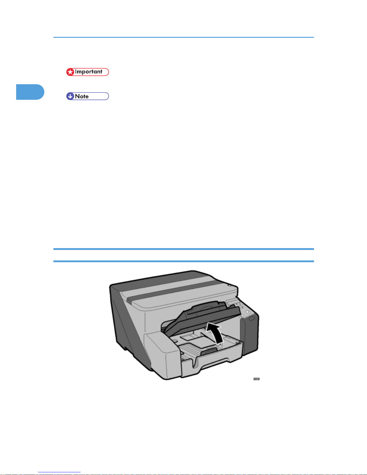
Load Paper
1. Raise the output tray.
1. Installation
28
1

2. Pull out the paper feed tray.
3. Squeeze the paper guide release and slide the paper guides to a position wider than the
paper size.
4. Fan the stack to remove static cling.
Installation Procedure
29
1
 Loading...