

Page 1

LSO
RICOH MV310
SERVICE MANUAL
May 22nd, 1995
Subject to change
Page 2
I
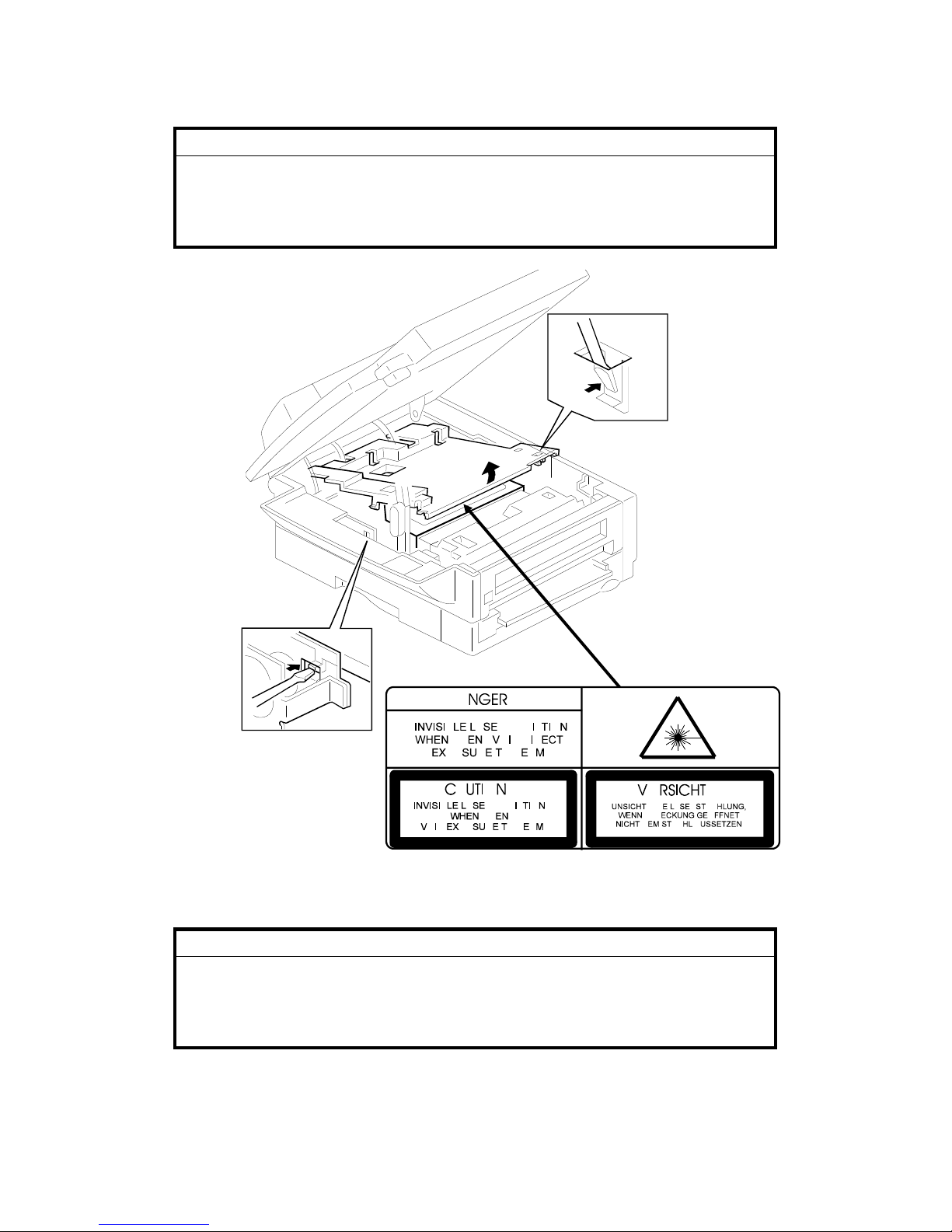
WARNING
THIS MACHINE CONTAINS A LASER BEAM GENERATOR. LASER
BEAMS CAN CAUSE PERMANENT EYE DAMAGE. DO NOT OPEN THE
LASER UNIT OR LOOK ALONG THE LASER BEAM PATH WHILE THE
MAIN POWER IS ON.
Lithium Batteries (Memory Back-up)
I
CAUTION
The danger of explosion exists if a battery of this type is incorrectly
replaced. Replace only with the same or an equiv al ent type
recommended by the manufacture r. Discard used batteries in
accordance with the manufactur er’ s instr uctions.
Page 3

Table of Contents
1. OVERALL MACHINE INFORMATION
1.1. SPECIFICATIONS . . . . . . . . . . . . . . . . . . 1-1
1.2. FEATURES . . . . . . . . . . . . . . . . . . . . . 1-3
1.3. COMPONENT LAYOUT . . . . . . . . . . . . . . . . 1-6
1.3.1. Mechanical Compon en ts . . . . . . . . . . . . . . 1-6
1.3.2. Electrical Compone nt s . . . . . . . . . . . . . . . 1-8
1. PCBs . . . . . . . . . . . . . . . . . . . . . . 1-9
2. Motors and Clutches . . . . . . . . . . . . . . . . 1-9
3. Sensors . . . . . . . . . . . . . . . . . . . . . 1-10
4. Interlock Switches . . . . . . . . . . . . . . . . . 1-10
5. Others . . . . . . . . . . . . . . . . . . . . . . 1-11
6. Options . . . . . . . . . . . . . . . . . . . . . 1-12
1.4. OVERALL MACHINE CONTROL . . . . . . . . . . . . 1-13
1.5. VIDEO DATA PATH . . . . . . . . . . . . . . . . . . 1-14
1.5.1. Transmission . . . . . . . . . . . . . . . . . . . 1-14
1.5.2. Reception . . . . . . . . . . . . . . . . . . . . 1-15
1.5.3. Copying . . . . . . . . . . . . . . . . . . . . . 1-16
1.5.4. Printing usin g th e Optional Printer Inte rface . . . . . . . 1-18
1.6. POWER DISTRIBUTION . . . . . . . . . . . . . . . . 1-19
1.6.1. Distribution Diagra m . . . . . . . . . . . . . . . . 1-19
1.6.2. Memory Back-up Circuit . . . . . . . . . . . . . . 1-20
2. DETAILED SECTION DESCRIPTIONS
2.1. SCANNER . . . . . . . . . . . . . . . . . . . . . 2-1
2.1.1. Overview . . . . . . . . . . . . . . . . . . . . 2-1
1. Book Scanner . . . . . . . . . . . . . . . . . . . 2-1
2. ADF . . . . . . . . . . . . . . . . . . . . . . . 2-2
2.1.2. Original Dete ctio n . . . . . . . . . . . . . . . . . 2-3
1. Book Scanner . . . . . . . . . . . . . . . . . . . 2-3
2. ADF . . . . . . . . . . . . . . . . . . . . . . . 2-5
2.1.3. Scanning . . . . . . . . . . . . . . . . . . . . 2-6
1. Contact Image Sensor . . . . . . . . . . . . . . . 2-6
2. Main Scan Resolution an d Widt h (Book Scanner) . . . . . 2-7
3. Main Scan Resolution an d Widt h (ADF) . . . . . . . . . 2-8
4. Sub Scan Resolution s and Len gt h (Bo ok Sca nn er) . . . . 2-8
5. Sub Scan Resolution s and Len gt h (ADF) . . . . . . . . 2-8
6. Sub Scan Resolution Conve rsion . . . . . . . . . . . 2-9
2.1.4. Drive Mechanism . . . . . . . . . . . . . . . . . 2-10
1. Book Scanner . . . . . . . . . . . . . . . . . . . 2-10
2. ADF . . . . . . . . . . . . . . . . . . . . . . . 2-11
Page 4

3. Scanner Po sition Fine Adjustment . . . . . . . . . . . 2-12
2.1.5. Pick-up and Feed (ADF) . . . . . . . . . . . . . . 2-13
2.1.6. Separation Mechanism (ADF) . . . . . . . . . . . . 2-13
2.1.7. Stamping (ADF) . . . . . . . . . . . . . . . . . . 2-14
2.1.8. Error Conditio ns . . . . . . . . . . . . . . . . . 2-15
1. Book Scanner . . . . . . . . . . . . . . . . . . . 2-15
2. ADF . . . . . . . . . . . . . . . . . . . . . . . 2-15
2.1.9. Vid eo Processing . . . . . . . . . . . . . . . . . 2-17
1. Analog Signal Processing . . . . . . . . . . . . . . 2-17
2. Digital Video Processing Steps . . . . . . . . . . . . 2-18
3. Video Processing Parameters . . . . . . . . . . . . 2-22
2.2. PRINTING . . . . . . . . . . . . . . . . . . . . . . 2-23
2.2.1. Printing Pro cess - Overview . . . . . . . . . . . . . 2-23
2.2.2. OPC Drum . . . . . . . . . . . . . . . . . . . . 2-24
2.2.3. Charge . . . . . . . . . . . . . . . . . . . . . 2-24
2.2.4. Laser Exposu re . . . . . . . . . . . . . . . . . . 2-26
1. Overview . . . . . . . . . . . . . . . . . . . . . 2-26
2. Block Diagram . . . . . . . . . . . . . . . . . . . 2-27
3. Error Conditions . . . . . . . . . . . . . . . . . . 2-27
4. Print Den sity Adjustment . . . . . . . . . . . . . . . 2-28
5. Enlargement . . . . . . . . . . . . . . . . . . . 2-28
6. Toner Saving Mode . . . . . . . . . . . . . . . . . 2-29
2.2.5. Toner Supply . . . . . . . . . . . . . . . . . . . 2-30
2.2.6. Development . . . . . . . . . . . . . . . . . . . 2-33
2.2.7. Paper Feed . . . . . . . . . . . . . . . . . . . 2-38
1. Overview . . . . . . . . . . . . . . . . . . . . . 2-38
2. Paper Lift Mechanism . . . . . . . . . . . . . . . . 2-39
3. Paper Size and Paper End Detection . . . . . . . . . . 2-40
4. Pick-up and Separation . . . . . . . . . . . . . . . 2-42
5. Drive Mechanism . . . . . . . . . . . . . . . . . 2-42
2.2.8. Registration . . . . . . . . . . . . . . . . . . . 2-45
2.2.9. Transfer and Separation . . . . . . . . . . . . . . 2-47
2.2.10. Cleaning . . . . . . . . . . . . . . . . . . . . 2-50
2.2.11. Fusing . . . . . . . . . . . . . . . . . . . . . 2-51
2.2.12. Page Separat ion and Data Reduction . . . . . . . . 2-55
2.2.13. Paper Size Sele ction . . . . . . . . . . . . . . . 2-57
2.3. SYSTEM FEATURES . . . . . . . . . . . . . . . . . 2-58
2.3.1. Power Saver Modes . . . . . . . . . . . . . . . . 2-58
1. Going into a Power Saver Mode . . . . . . . . . . . . 2-59
2. Going into Level 2 Mode from Le vel 1 Mod e . . . . . . . 2-61
3. Receiving a Fax Message in Power Sa ver Mod e . . . . . 2-63
4. Sending a Fax Message or Cop ying in Power Saver Mode . 2-65
2.3.2. Auto matic Service Ca lls . . . . . . . . . . . . . . 2-67
1. Service Call Conditions . . . . . . . . . . . . . . . 2-67
2. Excessive Jam Alarms . . . . . . . . . . . . . . . 2-68
3. Periodic Service Call . . . . . . . . . . . . . . . . 2-69
Page 5

4. PM Call . . . . . . . . . . . . . . . . . . . . . 2-70
5. Effective Term of Se rvice Ca lls . . . . . . . . . . . . 2-70
2.4. PCBs . . . . . . . . . . . . . . . . . . . . . . . 2-71
2.4.1. FCE . . . . . . . . . . . . . . . . . . . . . . 2-71
2.4.2. FDU . . . . . . . . . . . . . . . . . . . . . . 2-73
2.4.3. PSU . . . . . . . . . . . . . . . . . . . . . . 2-74
2.4.4. NCU (USA) . . . . . . . . . . . . . . . . . . . 2-75
1. Jumpers . . . . . . . . . . . . . . . . . . . . . 2-75
2.4.5. NCU (Europe/Asia) . . . . . . . . . . . . . . . . 2-76
1. Control Signals and Jump ers . . . . . . . . . . . . . 2-76
3. INSTALLATION
3.1. INSTALLING THE MACHINE . . . . . . . . . . . . . . 3-1
3.2. INITIAL PROGRAMMI NG . . . . . . . . . . . . . . . 3-1
3.3. OPTIONAL UNITS . . . . . . . . . . . . . . . . . . 3-2
3.3.1. Counter . . . . . . . . . . . . . . . . . . . . . 3-2
3.3.2. Printer I nt erface . . . . . . . . . . . . . . . . . . 3-3
4. SERVICE TABLES AND PROCEDURES
4.1. SERVICE LEV EL FUNCTIONS . . . . . . . . . . . . . 4-1
4.1.1. Bit Switch Prog rammin g (Fun ction 01) . . . . . . . . . 4-1
4.1.2. System Parameter List (Function 02) . . . . . . . . . 4-2
4.1.3. Error Code Display (Fun ctio n 03 ) . . . . . . . . . . . 4-2
4.1.4. Service Monitor Report (Fun ction 04) . . . . . . . . . 4-2
4.1.5. Protocol Dump (Function 05) . . . . . . . . . . . . 4-3
4.1.6. RAM Display/Rewrite (Funct ion 06) . . . . . . . . . . 4-3
4.1.7. RAM Dump (Function 06) . . . . . . . . . . . . . . 4-4
4.1.8. Counter Display/Rewrite (Function 07) . . . . . . . . . 4-4
4.1.9. NCU Parameters (Fun ction 08) . . . . . . . . . . . . 4-5
4.1.10. Modem Test (Function 08) . . . . . . . . . . . . . 4-6
4.1.11. DTMF Tone Test (Function 08) . . . . . . . . . . . 4-6
4.1.12. Modem Detection Test (Function 08) . . . . . . . . . 4-7
4.1.13. Ringer Test (Fun ction 08) . . . . . . . . . . . . . 4-7
4.1.14. Operat ion Panel Test (Function 09) . . . . . . . . . 4-8
4.1.15. LED Arra y Test (Function 10) . . . . . . . . . . . . 4-8
4.1.16. ADF Test (Function 10) . . . . . . . . . . . . . . 4-9
4.1.17. Book Mode Scanner Mech an ism Test (Funct ion 10) . . . 4-9
4.1.18. Auto Pa per Select Mode Test (Function 10) . . . . . . 4-10
4.1.19. Image Sensor Check/Clock Reset (Function 10) . . . . 4-10
4.1.20. Printer Test Pa tt erns (Function 11) . . . . . . . . . . 4-11
4.1.21. Printer Mechanism Test - Free Ru n (Fu nction 11) . . . . 4-12
4.1.22. RAM Tests (Functio n 1 2) . . . . . . . . . . . . . . 4-12
4.1.23. Software Down load (Function 12) . . . . . . . . . . 4-13
Page 6

4.1.24. Software Uplo ad (Fu nct ion 12) . . . . . . . . . . . 4-14
4.1.25. SRAM Data Downloa d (Function 12) . . . . . . . . . 4-15
4.1.26. Serial Numbe r (Function 14) . . . . . . . . . . . . 4-16
4.1.27. Service Statio n Tele ph on e Number (Function 13) . . . . 4-17
4.2. BIT SWITCHES . . . . . . . . . . . . . . . . . . . 4-18
4.2.1. System Switche s . . . . . . . . . . . . . . . . . 4-18
4.2.2. Scanner Switche s . . . . . . . . . . . . . . . . 4-28
4.2.3. Printer Switch es . . . . . . . . . . . . . . . . . 4-29
4.2.4. Communicatio n Swit ches . . . . . . . . . . . . . . 4-32
4.2.5. G3 Switches . . . . . . . . . . . . . . . . . . . 4-38
4.3. NCU PARAMETERS . . . . . . . . . . . . . . . . . 4-44
4.4. DEDICATED TRANSMISSION PARAMETERS . . . . . . . 4-72
4.4.1. Programming Proce du re . . . . . . . . . . . . . . 4-72
4.4.2. Paramete rs . . . . . . . . . . . . . . . . . . . 4-73
4.5. SERVI CE RAM ADDRESSES . . . . . . . . . . . . . . 4-75
4.6. SPECIAL TOOLS AND LUBRICANTS . . . . . . . . . . 4-87
4.7. PM TABLE . . . . . . . . . . . . . . . . . . . . . 4-87
5. REPLACEMENT AND ADJUSTMENT
5.1. EXTERIOR . . . . . . . . . . . . . . . . . . . . . 5-1
5.1.1. ADF . . . . . . . . . . . . . . . . . . . . . . 5-1
5.1.2. Operatio n P an el a nd Cop y Tray . . . . . . . . . . . 5-3
5.1.3. Platen Cover and Original Scales . . . . . . . . . . . 5-3
5.1.4. Top Cover and Exposure Glass . . . . . . . . . . . 5-4
5.1.5. Left, Front, and Rear Cover . . . . . . . . . . . . . 5-4
5.2. SCANNER . . . . . . . . . . . . . . . . . . . . . 5-5
5.2.1. Contact Image Sensor . . . . . . . . . . . . . . . 5-5
5.2.2. Fluorescent Lamp Sta bilize r . . . . . . . . . . . . . 5-6
5.2.3. Original Size, Plat en Co ver, and Scanner H. P. Sensors . . 5-6
5.2.4. Scanner Motor . . . . . . . . . . . . . . . . . . 5-7
5.3. LASER PRINTING COMPONE NTS . . . . . . . . . . . 5-7
5.3.1. Inner Cover . . . . . . . . . . . . . . . . . . . 5-7
5.3.2. Laser Unit . . . . . . . . . . . . . . . . . . . . 5-8
5.3.3. Laser Diode Unit and Hexagon al Mirror Mot or . . . . . . 5-9
5.4. DEVELOPMENT . . . . . . . . . . . . . . . . . . . 5-10
5.4.1. Master Drum . . . . . . . . . . . . . . . . . . . 5-10
5.4.2. Development Unit . . . . . . . . . . . . . . . . . 5-10
5.4.3. Transfer Roller . . . . . . . . . . . . . . . . . . 5-11
5.4.4. Main Moto r and Gea r s . . . . . . . . . . . . . . . 5-11
5.4.5. Replacing th e Deve lopment Unit . . . . . . . . . . . 5-12
5.5. FUSING . . . . . . . . . . . . . . . . . . . . . . 5-15
5.5.1. Thermisto r . . . . . . . . . . . . . . . . . . . . 5-15
5.5.2. Fusing Unit . . . . . . . . . . . . . . . . . . . 5-15
5.5.3. Hot Roller Strippers . . . . . . . . . . . . . . . . . . . . . . . . . . . 5-17
5.5.4. Fusing Lamp . . . . . . . . . . . . . . . . . . . . . . . . . . . 5-17
Page 7

5.5.5. Hot Roller . . . . . . . . . . . . . . . . . . . . 5-18
5.5.6. Pressure Roller . . . . . . . . . . . . . . . . . . 5-20
5.5.7. Thermost at an d Th ermofuse . . . . . . . . . . . . . 5-20
5.6. PAPER FEED . . . . . . . . . . . . . . . . . . . . 5-21
5.6.1. Paper Feed Roller and Clutch . . . . . . . . . . . . 5-21
5.6.2. Paper End Sensor . . . . . . . . . . . . . . . . . 5-21
5.6.3. Registratio n Sensor and Pressure Rollers . . . . . . . 5-22
5.6.4. Paper Feed Motor, Gears and Registration Roller . . . . 5-22
5.6.5. Bypass Feed Sensor . . . . . . . . . . . . . . . . 5-23
5.6.6. Paper Size Se nsor . . . . . . . . . . . . . . . . 5-23
5.7. PCBs . . . . . . . . . . . . . . . . . . . . . . . 5-24
5.7.1. PSU . . . . . . . . . . . . . . . . . . . . . . 5-24
5.7.2. NCU . . . . . . . . . . . . . . . . . . . . . . 5-24
5.7.3. FDU and FCE . . . . . . . . . . . . . . . . . . 5-25
5.7.4. Power Pack . . . . . . . . . . . . . . . . . . . 5-26
5.8. OTHERS . . . . . . . . . . . . . . . . . . . . . . 5-26
5.8.1. Ozone Filter and Fan Moto r . . . . . . . . . . . . . 5-26
5.8.2. Toner End Sensor . . . . . . . . . . . . . . . . . 5-27
5.9. ADF . . . . . . . . . . . . . . . . . . . . . . . . 5-27
5.9.1. ADF Ro ller Asssembly an d Covers . . . . . . . . . . 5-27
5.9.2. Pick-up Roller . . . . . . . . . . . . . . . . . . 5-28
5.9.3. Feed Roller . . . . . . . . . . . . . . . . . . . 5-28
5.9.4. Separation Roller . . . . . . . . . . . . . . . . . 5-29
5.9.5. ADF Motor and Covers . . . . . . . . . . . . . . . 5-29
5.9.6. R0 and R1 Rollers . . . . . . . . . . . . . . . . . 5-30
5.9.7. R2 Roller . . . . . . . . . . . . . . . . . . . . 5-30
5.9.8. Document Se nso r and Wid th Sen sor . . . . . . . . . 5-31
5.9.9. Scan Line Sensor . . . . . . . . . . . . . . . . . 5-32
5.9.10. Cover Sensors . . . . . . . . . . . . . . . . . . 5-32
5.10. 100 SHEET PAPER CASSETTE (OPTIONAL) . . . . . . . 5-34
5.10.1. Relay Connector and Gear Cover . . . . . . . . . . 5-34
5.10.2. Paper End Sensor a nd Drive Components . . . . . . . 5-35
5.10.3. Paper Size Sensor . . . . . . . . . . . . . . . . 5-36
5.11. IMAGE ADJUSTMENT . . . . . . . . . . . . . . . . 5-37
5.11.1. Overview . . . . . . . . . . . . . . . . . . . . 5-37
5.11.2. Scanner Parameters . . . . . . . . . . . . . . . 5-38
1. Contrast . . . . . . . . . . . . . . . . . . . . . 5-38
2. Margins . . . . . . . . . . . . . . . . . . . . . 5-38
5.11.3. Printer Parameters . . . . . . . . . . . . . . . . 5-40
1. Margin (Main Scan Direction) . . . . . . . . . . . . . 5-40
2. Margin (Sub Scan Direction ) . . . . . . . . . . . . . 5-41
5.11.4. Scanner Video Processing Para meters . . . . . . . . 5-42
1. Contrast . . . . . . . . . . . . . . . . . . . . . 5-42
2. Image P roce ssing Parameters Ad justment . . . . . . . . 5-43
Page 8

6. TROUBLESHOOTING
6.1. COPY QUALITY TROUBLESHOOTING . . . . . . . . . . 6-1
6.1.1. Blank Copies . . . . . . . . . . . . . . . . . . . 6-2
6.1.2. Black Copies . . . . . . . . . . . . . . . . . . . 6-4
6.1.3. Dirty Background . . . . . . . . . . . . . . . . . 6-5
6.1.4. Uneven Image Den sity . . . . . . . . . . . . . . . 6-6
6.1.5. Vertical Black Lines . . . . . . . . . . . . . . . . 6-7
6.1.6. Horizontal Black Line s . . . . . . . . . . . . . . . 6-8
6.1.7. Vertical White Line s . . . . . . . . . . . . . . . . 6-9
6.1.8. Horizontal White Lines . . . . . . . . . . . . . . . 6-10
6.1.9. Black Dots/Spots . . . . . . . . . . . . . . . . . 6-11
6.1.10. White Spots in Black Image Areas . . . . . . . . . . 6-12
6.1.11. Faint Copies . . . . . . . . . . . . . . . . . . 6-13
6.1.12. Vertical Black Band . . . . . . . . . . . . . . . . 6-15
6.1.13. Unfused Copies . . . . . . . . . . . . . . . . . 6-16
6.1.14. Ghost Image . . . . . . . . . . . . . . . . . . 6-16
6.1.15. Toner on the Back of the Printer Paper . . . . . . . . 6-17
6.1.16. Misaligned Output (Dat a shif te d to the right or le ft ) . . . 6-18
6.1.17. Misaligned Output (Image shifted vertically)/Reduced Image 6-18
6.2. MECHANICAL PROBLEMS . . . . . . . . . . . . . . 6-19
6.2.1. ADF . . . . . . . . . . . . . . . . . . . . . . 6-19
1. Non Feed . . . . . . . . . . . . . . . . . . . . 6-19
2. Jam . . . . . . . . . . . . . . . . . . . . . . . 6-20
3. Skew . . . . . . . . . . . . . . . . . . . . . . 6-21
4. Multi-feed . . . . . . . . . . . . . . . . . . . . 6-21
6.2.2. Book Scanner . . . . . . . . . . . . . . . . . . 6-22
1. Abnormal Noise . . . . . . . . . . . . . . . . . . 6-22
2. Scanner Home Position Error (Erro r Code 9-11) . . . . . 6-22
3. Automatic P ap er S election Error . . . . . . . . . . . . 6-23
4. Scanning Start Position Error (Error Code 1-09) . . . . . 6-23
6.2.3. Printer . . . . . . . . . . . . . . . . . . . . . 6-24
1. Non-feed . . . . . . . . . . . . . . . . . . . . . 6-24
2. Paper Jam - Inside the Printer . . . . . . . . . . . . 6-25
3. Jam - Fusing Exit . . . . . . . . . . . . . . . . . 6-26
4. Skew . . . . . . . . . . . . . . . . . . . . . . 6-27
5. Multi-feed . . . . . . . . . . . . . . . . . . . . 6-27
6.3. SERVICE CALL CONDITIONS . . . . . . . . . . . . . 6-28
6.4. ERROR CODES . . . . . . . . . . . . . . . . . . . 6-32
6.5. ELECTRICAL COMPONENT DE FECTS . . . . . . . . . 6-39
6.5.1. Defective Sensor Table . . . . . . . . . . . . . . . 6-39
6.5.2. Blown Fuse Tab le . . . . . . . . . . . . . . . . . 6-40
Page 9

1. OVERALL MACHINE INFORMATION
1.1. SPECIFICATIONS
Type
Desktop transceiver
Circuit
PSTN, PABX
Connection
Direct couple
Book Scanner
Document Size:
Smaller than 257 x 364 mm
[10.1 x 14.3 ins]
Thickness: Less than 30 mm
Weight: Less than 5 kg
ADF
Document Size
Length: 105 - 364 mm
[4.1 - 16.5 ins]
Up to 1200 mm [47.2 ins],
manually assisted
Width: 148 - 257 mm
[5.8 - 10.1 ins]
Thickness: 0.05 to 0.2 mm [2 to 8 mils]
(equivalent to 50 - 90 g/m
2
)
0.04 to 0.4 mm [1.6 to 16 mils],
manually assisted
(equivalent to 40 - 120 g/m
2
)
Document Feed
Automatic feed, face up
ADF Capacity
30 sheets (using 20 lb paper)
Scanning Method
Contact image sensor, with xenon lamp
Maximum Scan Width
256 mm [10.1 ins] ± 0.25%
Scan Resolution
Fax mode
Standard: 8 x 3.85 lines/mm [203 x 98 dpi]
Detail: 8 x 7.7 lines/mm [203 x 196 dpi]
Fine: 8 x 15.4 lines/mm [203 x 392 dpi]
Copy mode:
16 x 15.4 lines/mm [406 x 392 dpi]
Memory Capacity
ECM: 64 or 128 kB; single or double buffer
SAF: 576 kB (45 pages/A4)
Protocol
Group 3 with ECM
Compression
MH, MR, EFC, MMR, SSC (MMR only with
ECM)
Storage to SAF memory for tx: MMR and/or
raw data
Modulation
V.29 (QAM), V.27ter (PHM), V.21 (FM)
Data Rate (bps)
9600/7200/4800/2400, Automatic fallback
I/O Rate
With ECM: 0 ms/line
Without ECM: 2.5, 5, 10, 20, or 40 ms/line
Transmission Time
9 s at 9600 bps; Measured with G3 ECM using memory for a CCITT #1 test document
(Slerexe letter) using standard resolution
Printing System
Laser printing, plain paper, dry toner
Printing Time
10 ppm for A4 size paper
Paper Size
Standard Cassette:
USA: Half-Letter, Letter, Legal
Europe/Asia: A4, A5, B5, F, F4
Optional 100 Sheet Cassette:
USA: Half-letter, Letter, Legal
Europe/Asia: A4, A5, B5 lengthwise, F/F4
Paper Capacity
Standard Cassette: - 250 sheets
Optional 100 Sheet Cassette:
- 100 sheets
Bypass Feeder: - 1 page
Maximum Printing Width
248 mm [9.8 ins]
Printer Resolution
Fax/Copy Mode: 16 x 15.4 lines/mm
[406 x 392 dpi]
Printer Mode: 300 x 300 dpi
Power Supply
USA: 115 ± 20 Vac, 60 ± 1 Hz
Europe/Asia: 220 Vac +20/-10%, 50 ± 1 Hz
May 22nd, 1995 OVERALL MACHINE INFORMATION
SPECIFICATIONS
1-1
Page 10

Power Consumption
Standby: Minimum 2 W, Normal 70 W
Transmitting: 35 W
Receiving: 200 W
Copying: Normal 300 W, Maximum 800 W
Operating Environment
Temperature: 17 - 28 °C [63 - 82 °F]
Humidity: 40 - 70 %Rh
Dimensions (W x D x H)
555 x 555 x 342 mm [21.9 x 21.9 x 13.5 ins]
Excluding handset, trays, and optional units
Weight
30 kg [66 lbs]
Excluding handset, trays, and optional units
OVERALL MACHINE INFORMATION May 22nd, 1995
SPECIFICATIONS
1-2
Page 11
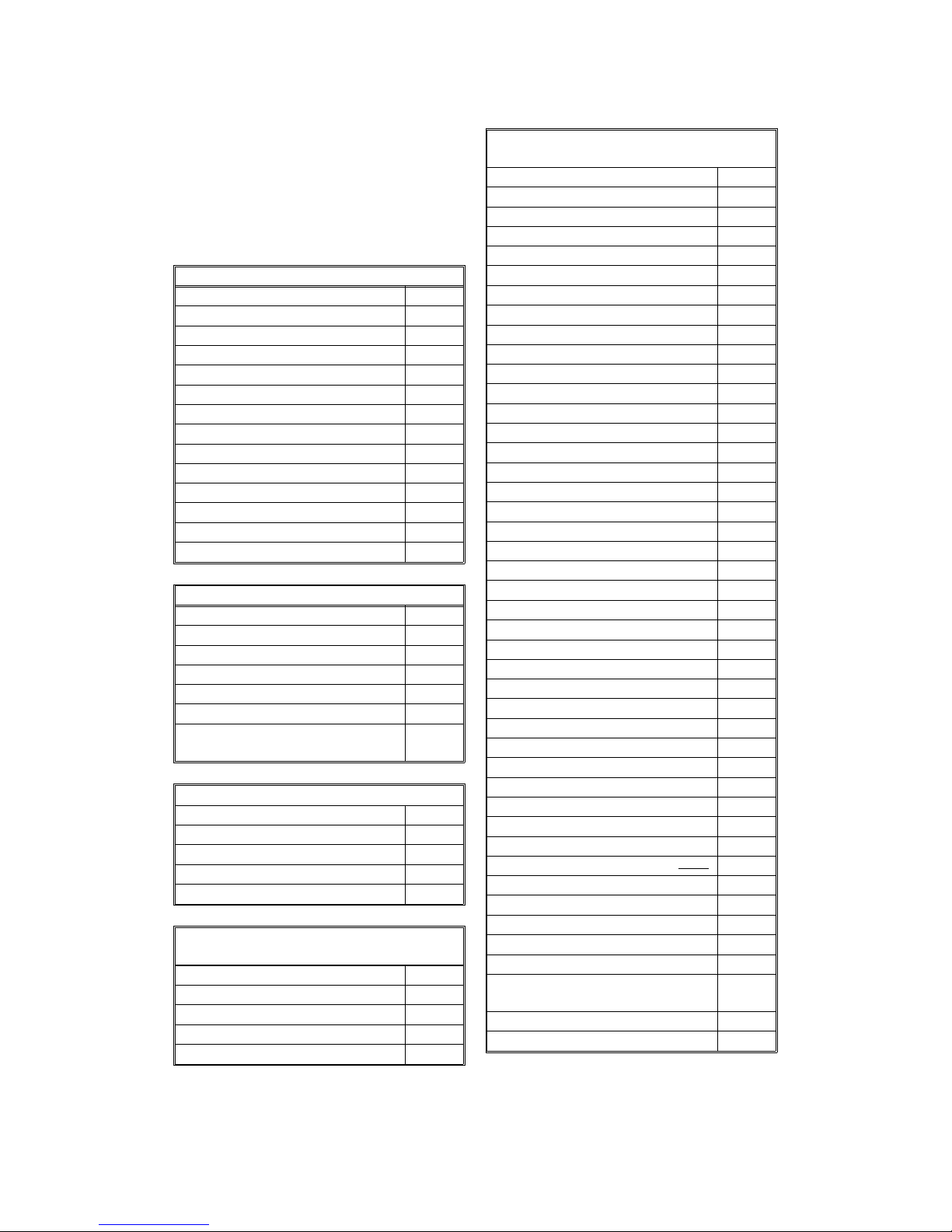
1.2. FEATURES
KEY: O = Used, X = Not Used
A = With optional 100 sheet cassette only
B = With optional counter only
C = With optional handset only
D = With printer interface only
Equipment
ADF O
Book scanner O
Built-in handset X
Bypass feed: 1 sheet O
Optional cassette: 100 sheets A
Cabinet X
Counter B
Cutter X
Handset C
Hard disk X
Manual feed mechanism X
Marker (Stamp) O
Monitor speaker O
Printer interface option D
Video Processing Features
Contrast O
Auto image density control O
Halftone (Basic & Error Diffusion) O
MTF O
Reduction (Fax) O
Resolution O
Smoothing to 16 x 15.4 l/mm
(Fax)
O
Communication Features - Aut o
Automatic fallback O
Automatic redialing O
Confidential reception X
Dual Access O
Substitute reception O
Communication Features -
User Selectable
Action as a transfer broadcaster X
AI Redial (last ten numbers) X
Answering machine interface X
Authorized Reception O
Auto-answer delay time X
Communication Features -
User Selectable
Auto dialing (pulse or DTMF) O
Auto Document X
Auto image density selection O
Automatic Voice Mess age X
Batch Transmission X
Broadcasting O
Chain Dialing X
Communication Result Display X
Confidential ID Override X
Confidential Transmission X
Direct Fax Number Entry O
Economy Transmission X
Fax on demand X
Forwarding X
Free Polling X
Groups (3 groups) O
Group Transfer Station X
Hold X
ID Transmission Option X
Immediate Redialing O
Immediate transmission O
Keystroke Programs X
Memory transmission O
Multi-step Transfer X
Next Transfer Station X
OMR X
On Hook Dial O
Ordering Toner X
Page Count O
Personal Codes X
Personal Codes with Conf. ID X
Polling Reception O
Polling Transmission X
Polling tx file lifetime in the SAF X
Quick Dial (20 stations) O
Reception modes (Fax, Tel,
Auto) O
Reduction O
Remote control features X
Remote Transfer X
Restricted Access X
Secured Polling X
Secured Polling with Stored ID
Override
X
Secure Transmission X
Send Later O
May 22nd, 1995 OVERALL MACHINE INFORMATION
FEATURES
1-3
Page 12
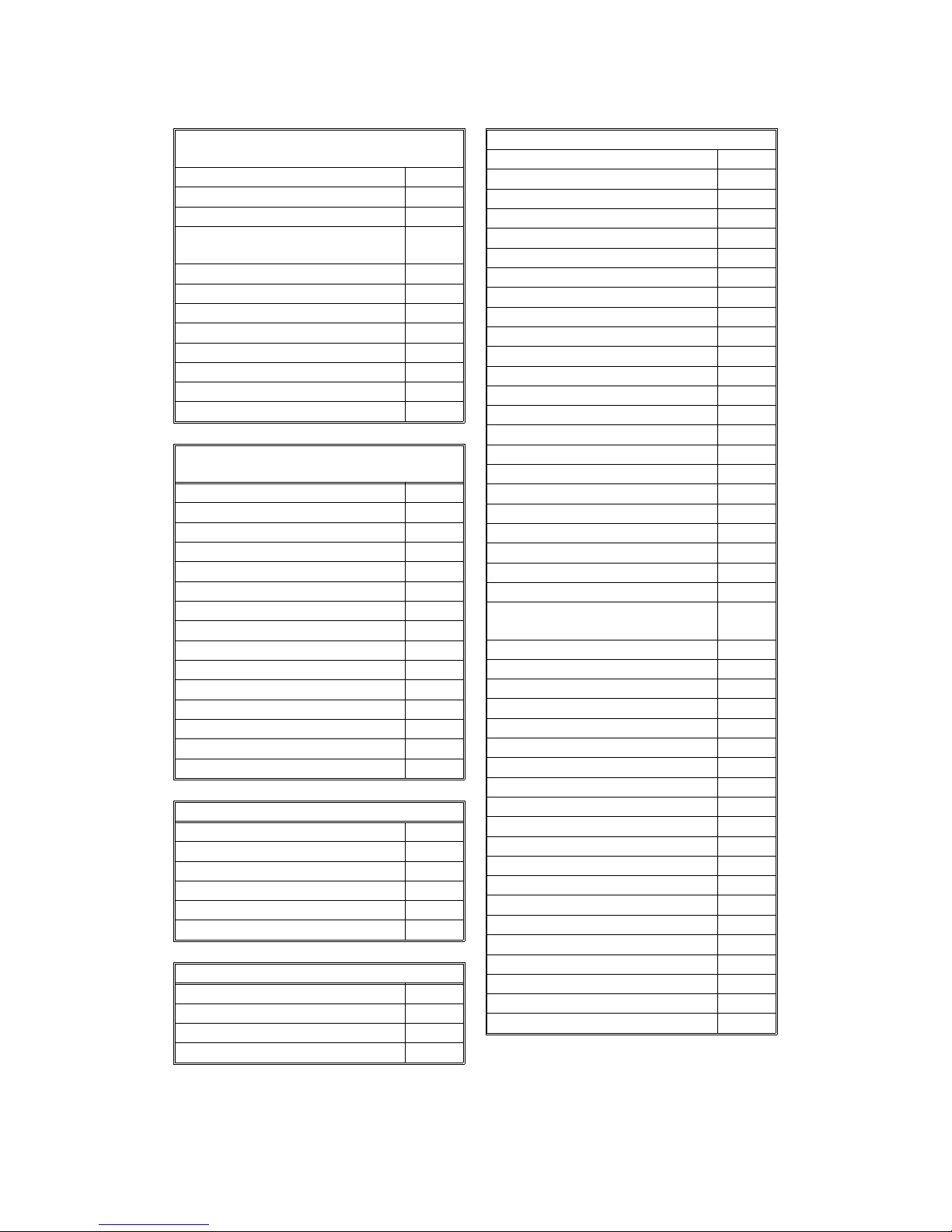
Communication Features -
User Selectable
Silent ringing detection X
Specified Image Area X
Speed Dial (50 stations) O
Super Fine Resolution
(16 x15.4 l/mm : 400 x 400 dpi)
X
Telephone Directory X
Tonal Signal Transmission O
Transfer Request X
Transmission Deadline (TRD) X
Turnaround Polling X
Two-step Transfer X
Two in one X
Voice Request (immed. tx only) X
Communication Features -
Service Selectable
AI Short Protocol O
Auto-reduction override option O
Busy tone detection O
Closed Network (tx and rx) X
Continuous Polling Reception X
Dedicated tx parameters O
ECM O
EFC O
Inch-mm conversion X
Page retransmission O
Page separation mark O
Protection against wrong conn. O
Resol’n stepdown override option X
Short Preamble X
Well log O
Copier Features
Auto Image Density O
Auto Paper Select (Book mode) O
Reduction/Enlargement O
Erase center/border O
Distribution number printing O
Center marks O
Other User Features
Area Code Prefix X
Auto Service Call O
Center mark O
Checkered mark X
Other User Features
Clearing a memory file O
Clearing a polling file O
Clock O
Confidential ID X
Copy mode O
Copy Mode Restriction X
Counters O
Daylight Saving Time (USA only) O
Destination Check X
Direct entry of names O
File Retention Time X
File Retransmission O
Function Programs X
ID Code X
Label Insertion ("From xxx") X
Language Selection O
LCD contrast control Service
Memory Lock X
Memory Lock ID X
Modifying a memory file X
Multi Sort Document Reception X
Multicopy mode (up to 99) O
Own telephone number X
Power Saver (Night Timer and
standby mode)
O
Print density control O
Printing a memory file O
RDS on/off O
Reception Mode Switching Timer X
Reception time printing X
Remaining memory indicator O
Remote ID X
Reverse Order Printing X
RTI, TTI, CSI O
Secure ID X
Service Report Transmission O
Speaker volume control O
Specified Cassette Selection X
Substitute reception on/off O
Telephone line type O
Toner saving mode O
TTI on/off O
User Function Keys X
User Parameters O
Wild Cards O
OVERALL MACHINE INFORMATION May 22nd, 1995
FEATURES
1-4
Page 13
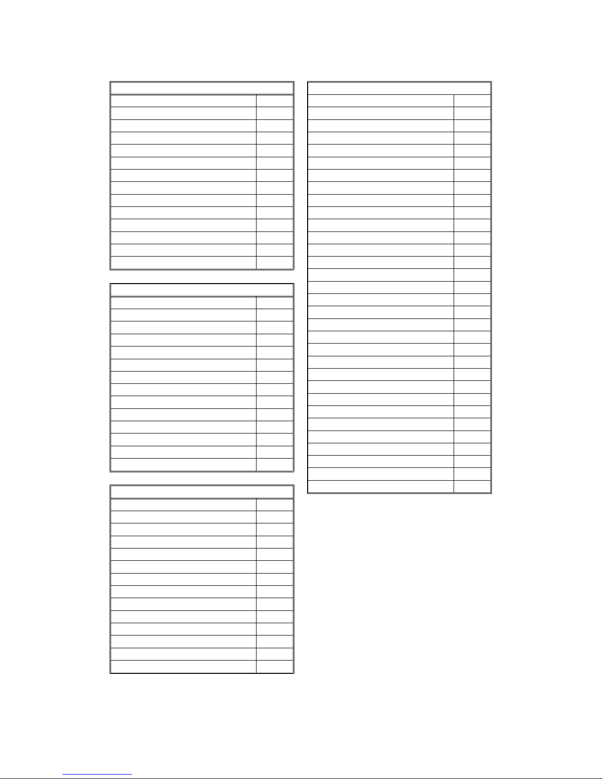
Reports - Automatic
Charge Control Report X
Communication Failure Report O
Confidential File Report X
Error Report O
Memory Storage Report O
Mode Change Report X
Polling Clear Report X
Polling Reserve Report O
Polling Result Report O
Power Failure Report O
TCR O
Toner Cassette Order Form X
Transfer Result Report X
Transmission Result Report O
Reports - User-initiated
Authorized Reception List O
Charge Control Report X
File List O
Forwarding List X
Group List O
Personal Code List X
Program List X
Quick Dial List O
Specified Cassette Selection List X
Speed Dial List O
TCR O
Transmission Status Report X
User Function List X
User Parameter List O
Service Mode Features
Auto Paper Select Test O
Back-to-back test O
Bit switch programming O
Book Test O
Buzzer test O
Cable equalizer O
Comm. parameter display O
Counter check O
Country code O
DTMF tone test O
Echo countermeasure O
Effective term of service calls O
Error code display O
Excessive jam alarm O
Service Mode Features
File Transfer O
Hex Dump List E
LCD contrast adjustment O
Line error mark O
Memory file printout (all files) O
Modem test O
NCU parameters O
Operation panel test O
Periodic service call O
PM Call O
Printer mechanism test X
Printer test patterns O
Programmable attenuation X
Protocol dump list O
RAM display/rewrite O
RAM dump O
RAM test O
Ringer test X
Scanner lamp test O
Scanner mechanism test O
Sensor initialization X
Serial number O
Service monitor report O
Service station number O
Software upload/download O
SRAM data download O
Status Sheet D
System parameter list O
Technical data on the TCR O
Thermal head parameters X
Transmission Status Report X
User data transfer O
Memory Files
Max. number of files: 100
Max. number of stations/file: 100
Max. number of stations overall: 200
Max. number of pages overall: 150
May 22nd, 1995 OVERALL MACHINE INFORMATION
FEATURES
1-5
Page 14
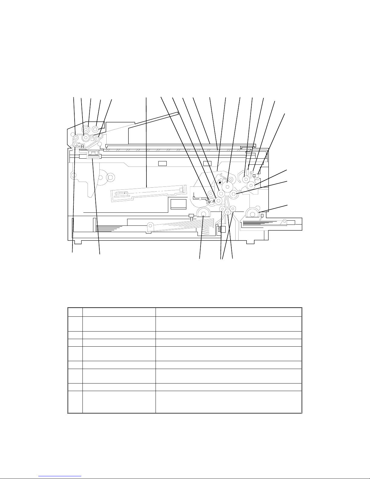
1.3. COMPONENT LAYOUT
1.3.1. Mechanical Components
No. Name Description
1
Scanner Contains a contact image sensor and a xenon lamp
driver.
2 R1 Roller Feeds the document through the scanner.
3 R0 Roller Feeds the document into the scanner.
4
Separation roller Prevents more than one sheet from feeding into the
scanner.
5 Document Feed Roller Feeds the document into the scanner.
6
Pick-up Roller Picks up pages of the document from the document
table one at a time.
7 R2 Roller Feeds the document through the scanner.
8
Laser Unit This consists of the LDDR (Laser Diode Driver),
Focusing lens, Fθ Lenses, Hexagonal mirror motor, and
other laser optic components.
1
2
3
5
7
6
4
8
9
10
11
12
13 14
15
16
17
18
19
20
21
22
25 24
23
H521V501.wmf
OVERALL MACHINE INFORMATION May 22nd, 1995
COMPONENT LAYOUT
1-6
Page 15

No. Name Description
9
Toner Supply Bar This stirs up and transfers toner to the toner application
roller.
10 Toner Application Roller This roller transfers toner to the development roller.
11 Development Roller This roller applies toner to the latent image on the drum.
12
Platen Cover This covers the original which was placed on the
exposure glass.
13 Exposure Glass Book scanner reads the original on it.
14
CTM (Cleaning Toner
Magazine)
This consists of the toner cartridge, cleaning unit, used
toner tank, charge corona unit, and quenching lamp.
15
OPC Drum The latent image is written to this Organic
Photoconductor Drum.
16 Hot Roller Heat from this roller fuses the toner to the copy paper.
17
Cleaning Pad This cleans up and spreads silicone oil on the surface
of the hot roller.
18 Hot Roller Strippers These take the paper off the hot roller after fusing.
19 Paper Feed-out Rollers These feed the paper out of the printer.
20 Fusing Pressure Roller This applies pressure to the paper during fusing.
21
Transfer Roller This applies a charge to the paper to pull the toner off
the drum and onto the copy paper.
22
Paper Feed Rollers (100
Sheet Cassette)
These pick up the top sheet of paper from the stack in
the optional 100 sheet cassette and feed it into the
printer.
23 Registration Roller This carries out the registration process.
24
Paper Feed Pressure
Rollers
These feed paper from the cassette or bypass feed slot
into the printer.
25
Paper Feed Rollers These pick up the top sheet of paper from the stack in
the cassette and feed it into the printer.
May 22nd, 1995 OVERALL MACHINE INFORMATION
COMPONENT LAYOUT
1-7
Page 16
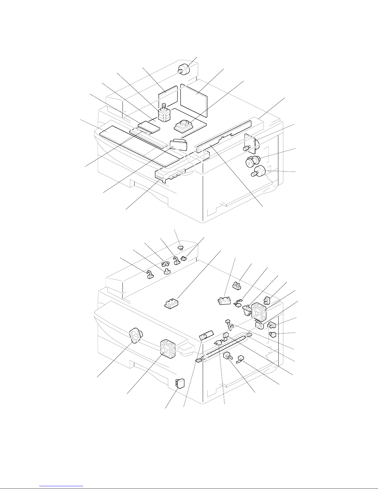
1.3.2. Electrical Components
3
4
1
5
16
15
6
7
8
14
9
10
11
12
13
2
H521V503.wmf
17
24
20
21
23
19
22
25
26
27
28
29
18
30
31
32
33
34
35
36
37
38
39
40
41
42
H521V504.WMF
OVERALL MACHINE INFORMATION May 22nd, 1995
COMPONENT LAYOUT
1-8
Page 17

1. PCBs
No. Name Description
3
FDU (Facsimile Driver
Unit)
This board contains drivers for the motors, a dc-dc
converter, the energy saving mode cpu, and other drive
electronics.
2
FCE (Facsimile Control
Engine)
This board controls the machine. It contains the main
cpu, flash ROM, system RAM, and so on.
5
NCU (Network Control
Unit)
This board contains a relay and switches for interfacing
the machine to the network and the handset.
1
OPU (Operation Panel
Unit)
This board controls the operation panel.
7
PSU (Power Supply Unit) This board supplies power to the machine, and
switches the fusing lamp on/off.
15
LDDR (Laser Diode
Driver)
This board drives the laser diode.
14
Power Pack This supplies high voltages to the corona wire, transfer
roller, and development bias terminal.
9
Contact Image Sensor
and Xenon Lamp
This sensor reads and converts the light reflected from
the document into an analog video signal. It uses an
RMLA (Roof Mirror Lens Array ) sensor unit.
The xenon lamp which illuminates the document is
contained in this unit.
16
IC Card This contains a DRAM which is used as page memory
for 400 x 400 dpi printing of incoming B4 faxes.
2. Motors and Clutches
No. Name Description
6 ADF Motor This stepper motor drives the scanner.
10
Main Motor This brushless dc motor drives the drum, fusing unit,
development unit, and CTM.
12
Paper Feed Motor This stepper motor drives the registration roller and the
paper feed mechanisms in the cassettes.
8
Hexagonal Mirror Motor This high-speed dc motor drives the hexagonal mirror
in the laser printer optics.
41
Ozone Fan Motor This removes ozone-laden air from the vicinity of the
drum, and filters out the ozone.
29 Cooling Fan Motor This cools the interior of the machine.
4 Scanner Motor This stepper motor drives the book scanner.
11
Paper Feed Clutch This transfers main motor drive to the cassette and
bypass tray paper feed mechanisms.
May 22nd, 1995 OVERALL MACHINE INFORMATION
COMPONENT LAYOUT
1-9
Page 18
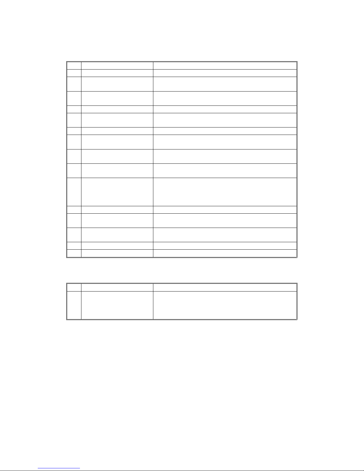
3. Sensors
No. Name Description
17 Document Sensor This detects the presence of a document in the feeder.
19
Scan Line Sensor This detects when a page is approaching the auto
shading position.
20
Document Width Sensor This detects when a B4 width [10.1"] document has
been placed in the feeder.
39 Toner End Sensor This detects when the toner has run out.
40
Paper Size Detector This detects the paper size installed in the cassette.
The user must install the correct actuator.
33 Paper End Sensor This detects when the paper in the cassette has run out.
37
Registration Sensor This detects when paper has reached the registration
roller.
31
Paper Feed-out Sensor This detects when the paper has been fed out of the
printer.
32
Paper Exit Cover Switch This detects whether the paper feed-out cover is open
or closed.
36
Bypass Feed Sensor This detects when a sheet of paper has been inserted
into the bypass feed slot. Then the registration roller
feeds the paper a short distance into the machine to
prepare for printing, and stops.
21 ADF Cover Switch This detects whether the ADF cover is open or closed.
28
Scanner Home Position
Sensor
This detects when the image sensor is at home position.
2324Paper Size Sensors These detect the size of the paper which was placed
on the exposure glass.
25 Platen Cover Sensor This detects whether the platen cover is open or closed.
22 ADF Switch This detects whether the ADF unit is open or closed.
4. Interlock Switches
No. Name Description
27
30
Fusing Unit Cover
Interlock Switches
If the fusing unit cover and/or top cover are open, these
interlock switches interrupt the +5VLD power supply for
the laser diode and the +24VD power supply for the
power pack, motors, and other components.
OVERALL MACHINE INFORMATION May 22nd, 1995
COMPONENT LAYOUT
1-10
Page 19

5. Others
No. Name Description
18
Stamper Ass’y This stamps a red circle on each page that is
successfully fed through the scanner.
38
Thermostat This interrupts the ac power supply to the fusing lamp if
the temperature of the thermostat surface exceeds
400°C.
35 Thermistor This monitors the temperature inside the fusing unit.
34 Fusing Lamp This fuses the toner to the paper.
42
Monitor Speaker This allows the user to listen to the condition of the
telephone line.
26
Zener Diode This ensures that the charge given to the drum by the
charge corona wire does not exceed -750 volts.
13 Lamp Stabilizer This supplies power to the xenon lamp.
May 22nd, 1995 OVERALL MACHINE INFORMATION
COMPONENT LAYOUT
1-11
Page 20
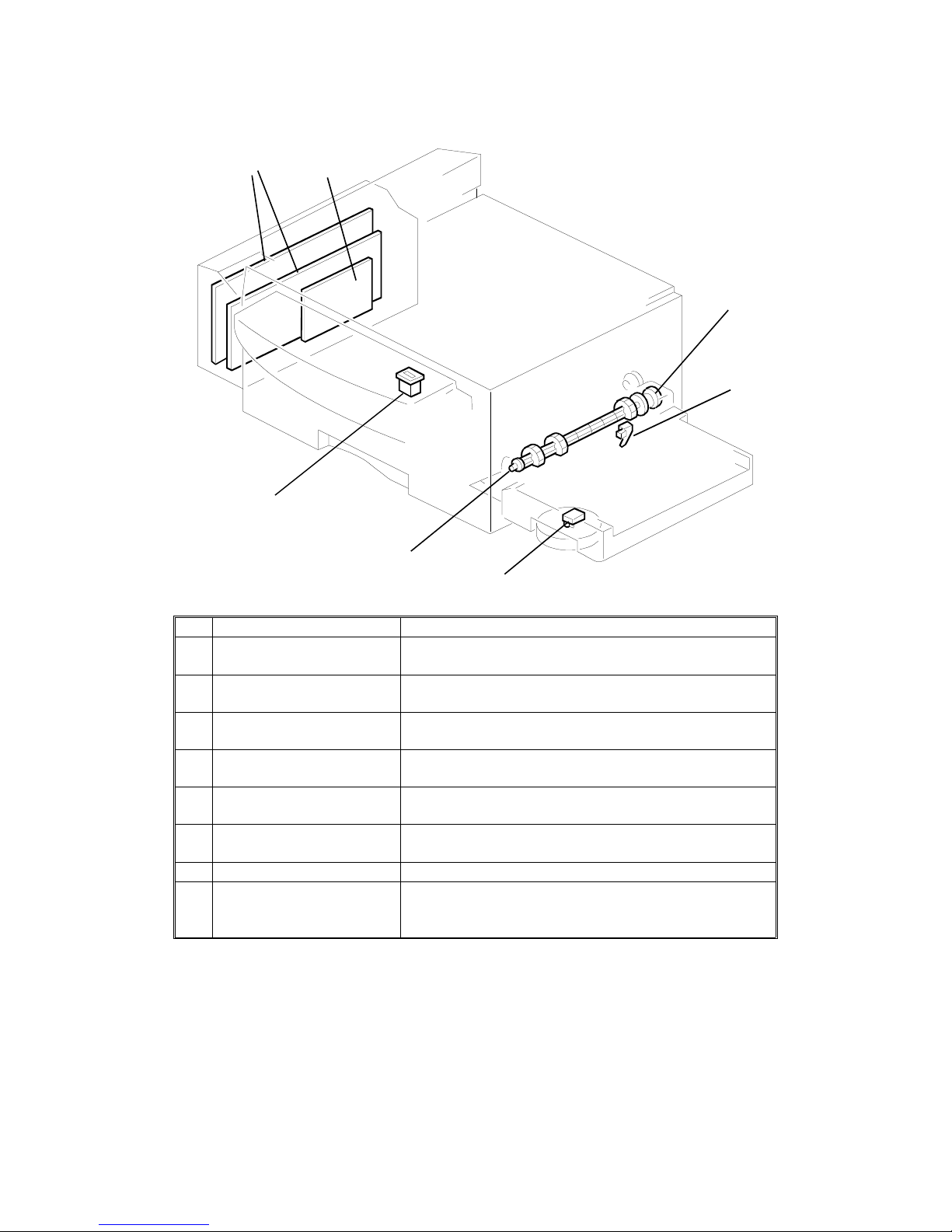
6. Options
No. Name Description
1
Printer Interface This allows the machine to be connected to a computer
as a laser printer.
2
RS232C Interface Board* This allows the machine to be connected to a computer
as an external fax device for example.
3
Paper Feed Clutch (100
Sheet Cassette)
This transfers motor drive to the mechanisms in the
100 sheet cassette.
4
Paper End Sensor (100
Sheet Cassette)
This detects when the paper in the optional 100 sheet
cassette has run out.
5
Paper Size Detector (100
Sheet Cassette)
This detects the paper size installed in the optional 100
sheet cassette.
6
Paper Feed Roller (100
Sheet Cassette)
This feeds paper from the 100 sheet cassette into the
machine.
7 Counter This counts the number of prints.
8
100 Sheet Cassette This increases the paper capacity of the machine, and
allows the machine to have more than one paper size
available at the same time.
* This option may not be available in some countries.
12
3
4
5
6
7
H521V505.wmf
OVERALL MACHINE INFORMATION May 22nd, 1995
COMPONENT LAYOUT
1-12
Page 21
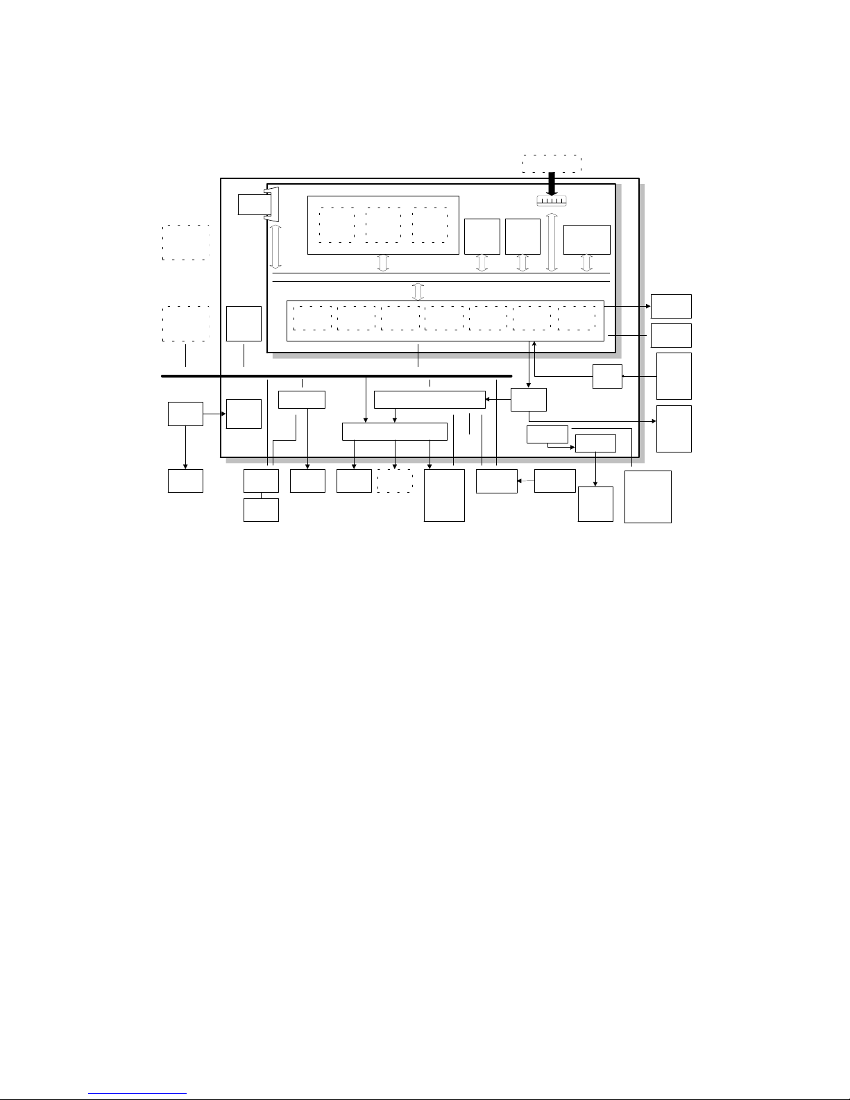
1.4. OVERALL MACHINE CONTROL
The FCE (Facsimile Control Engine) board contain s the FCIP (Facsimile Control and Image Processor), DRAM, SRAM, Syst em ROM, and video
processing memory, and it controls the entire system through th e FDU (Facsimile Driver Unit) board.
There are two cpus in the mach ine : the main cpu (FCIP) on the FCE board
and the energy saver cpu on the FDU board. In energy saver mode, the main
CPU switches off and the energy saver CPU takes over.
The FCIP consists of the following component blocks:
• MDM - Modem• RU8 CPU - Main CPU
• DMAC - DMA Controller• LIF- Laser Interface
• DIP - Digital Image Processor• PRIF - Printer Interface
• DCR - Data Compression and Reconstruction
The 4 MB DRAM contains the SAF memory, ECM buffer memory, work area,
and page memory. For B4 size copies at 16 x 15.4 dot/mm resolution, a page
memory IC card is installed. A rechargeable battery backs up th e DRA M for
one hour.
The system ROM uses a 512 KB (4 Mbits) flash ROM. Software in this ROM
can be rewritten from the IC card slot or by RDS.
FCE
FCE
Contact
Image
Sensor
Amp
Optional
100 Sheet
Cassette
Optional
Printer I/F
Energy
Saver
CPU
System
ROM
(Flash)
System
RAM
(SRAM)
DATA/ADDRESS BUS
Optional
RS232C I/F
Video
SRAM
Drivers
(FPD)
Driver
LDDR
Thermistor
Scanner
and
printer
components
and
sensors
Operation
Panel
Driver
Optional
Counter
Power
Pack
SpeakerNCU
Handset
Control
Signals
DRAM
System
RAM
ECM/SAF
Memory
Page
Memory
FCIP
MDM
CPU
RU8
DMAC DCR DIP LIF
External I/O (EXIO)
DC-DC
Converter
Hybrid IC
(HIC)
PSU
Fusing
Lamp
Page
Memory
PRIF
PSIF
Sensors
Paper
feed
motor
Book scanner
components
and
ADF sensor
ADF
and
book
scanner
motors
FDU
H521V506.wmf
May 22nd, 1995 OVERALL MACHINE INFORMATION
OVERALL MACHINE CONTROL
1-13
Page 22
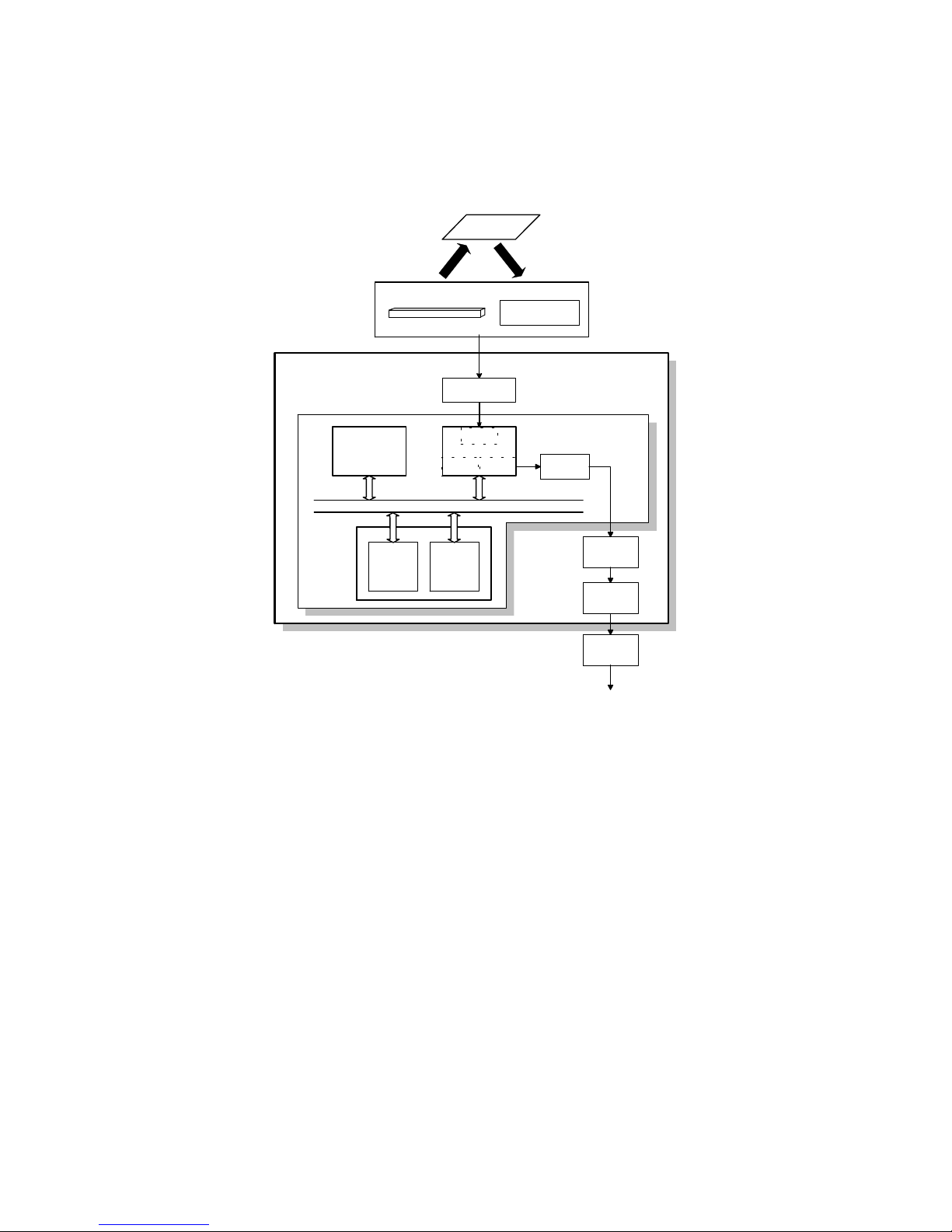
1.5. VIDEO DATA PATH
1.5.1. Transmission
Immediate Transmission:
Scanned data form the contact imag e sen sor passes to the DIP block in the
FCIP. After analog/digital video processing, the DCR block comp resse s t he
data for transmission. The co mpre ssed data then passes either to the FIFO
memory or to the ECM memory, before it is sent to the telephone line through
the modem.
Memory Transmission:
First, the scanned data is stored in the SAF memory after compressio n in the
DCR block.
At the time for transmission, the DCR block decompre sses the data from the
SAF memory, then compresses it again after handshaking with the oth er te rminal is done. The compressed data the n passes eit he r to th e FIFO memory
or to the ECM memory, before it is sent to the telephone line through the modem.
FDU
FCE
DRAM
Video
Processing
Memory
Amplifier
Attenuator
Line
Buffer
/FIFO
Memory
ECM/
SAF
Memory
NCU
Amplifier
MDM
FCIP
DATA/ADDRESS BUS
HIC
To the network
Original
Image Sensor
Xenon Lamp
Contact Image Sensor Assembly
DCR
DIP
DIP: Digital Image Processor
DCR: Data Compression and Reduction
MDM: Modem
H521V507.wmf
OVERALL MACHINE INFORMATION May 22nd, 1995
VIDEO DATA PATH
1-14
Page 23
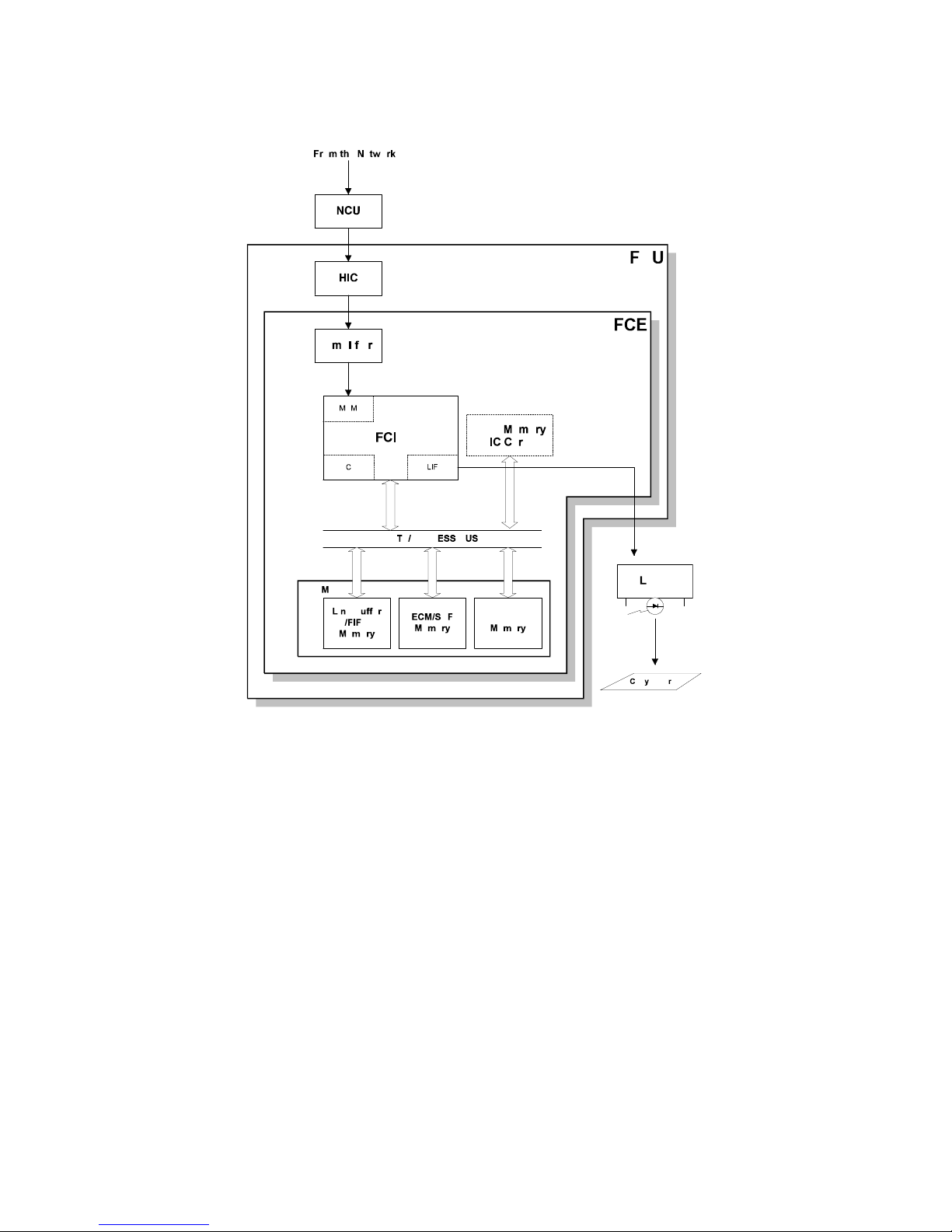
1.5.2. Reception
Data from the line passes to the modem th rou gh the NCU and hybrid IC. After the modem demodulates the dat a, the data pa sses to the DCR block,
through either the FIFO or the ECM memory, where the data is decompressed to raster imag e d at a. At the same time, the compressed data pa sses
to the SAF memory as a backup in case of mechanical problems during printing (substitute rece pt ion).
The raster image data is then p asse d t o t he pa ge memo ry fo r printing. After a
page of data has been stored in the pag e memo ry, the data is sent to the
LDDR through the LIF block.
MDM: Modem
DCR: Data Compression and Reduction
LIF: Laser Interface
H521V508.wmf
May 22nd, 1995 OVERALL MACHINE INFORMATION
VIDEO DATA PATH
1-15
Page 24
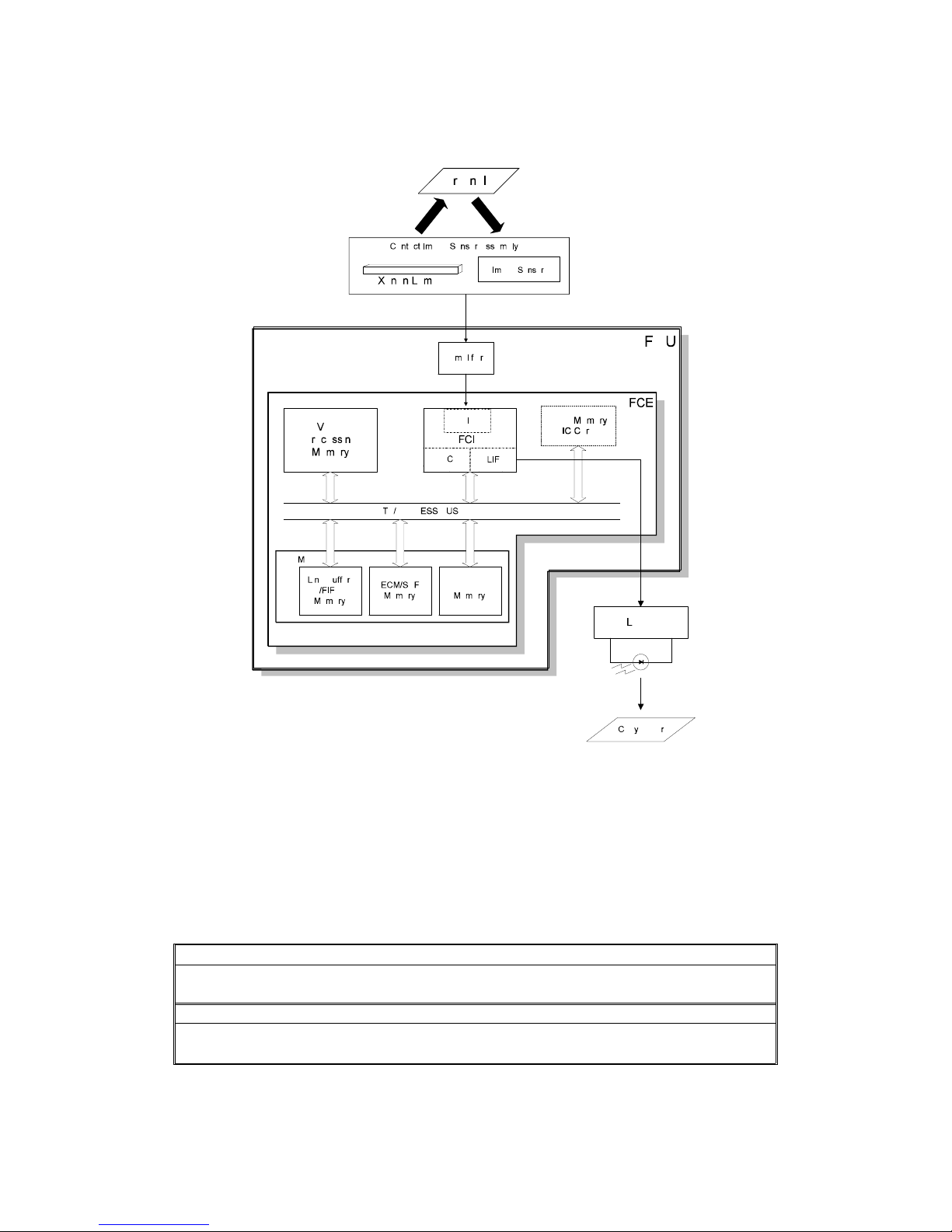
1.5.3. Copying
The scanned data passe s to th e pa ge memory af ter video processing in the
DIP block. After a page of data ha s be en sto red in the page memory, the data
is sent to the LDDR through the LIF block.
Reproduction/Enlargem ent Rati os
The following reproduction ratios are available:
Reduction 50% 65% 71% 74% 77% 82% 87% 93%
US Yes Yes No Yes Yes No No Yes
Europe/Asia Yes No Y es No No Yes Yes Yes
Enlargement 115% 121% 122% 129% 141% 155% 200%
US NoYesNoYesNoYesYes
Europe/Asia Yes No Y es No Yes No Y es
DIP: Digital Image Processor
DCR: Data Compression and Reduction
LIF: Laser Interface
H521V509.wmf]
OVERALL MACHINE INFORMATION May 22nd, 1995
VIDEO DATA PATH
1-16
Page 25
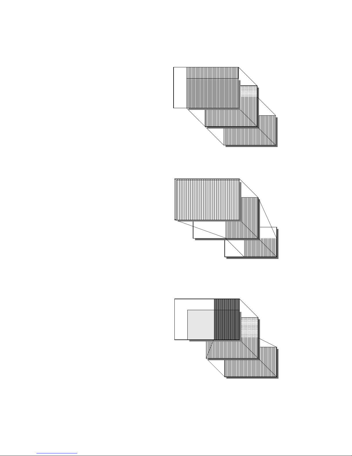
Reduction and Enlargement
The reduction/e nla rgement process
is done in two steps, one at the scanner, and the other at the printer.
At the scanner, the machine changes
the motor speed to get a reduced/enlarged image in the sub-scan
direction. For example, the machine
doubles the motor speed to get 50%
reduction (halving the numb er of
scan lines), and slows the motor
speed down by half to get 200% enlargement (doubling the number of
scan lines). The scanne r alwa ys
scans the full B4 (216 mm) width in
the main scan direction. The sca nned
data is then stored in the page memory for printing.
At the printer, the machine deletes
certain specified bits from each line
to reduce the printing image in the
main-scan direction. For examp le,
every other bit is deleted to get a
50% reduced image.
Also, the machine chang es th e laser
pulse width for each pixel to enlarg e
the printing image in the main-scan
direction. For example, the machine
doubles the pulse width to get a
200% enlarged image.
Scanner
Page Memory
Printer
Original
H521V513.wmf
Full Size
Scanner
Page Memory
Printer
Original
H521V514.wmf
50% Reduction
Scanner
Page Memory
Printer
Original
H521V515.wmf
200% Enlargement
May 22nd, 1995 OVERALL MACHINE INFORMATION
VIDEO DATA PATH
1-17
Page 26
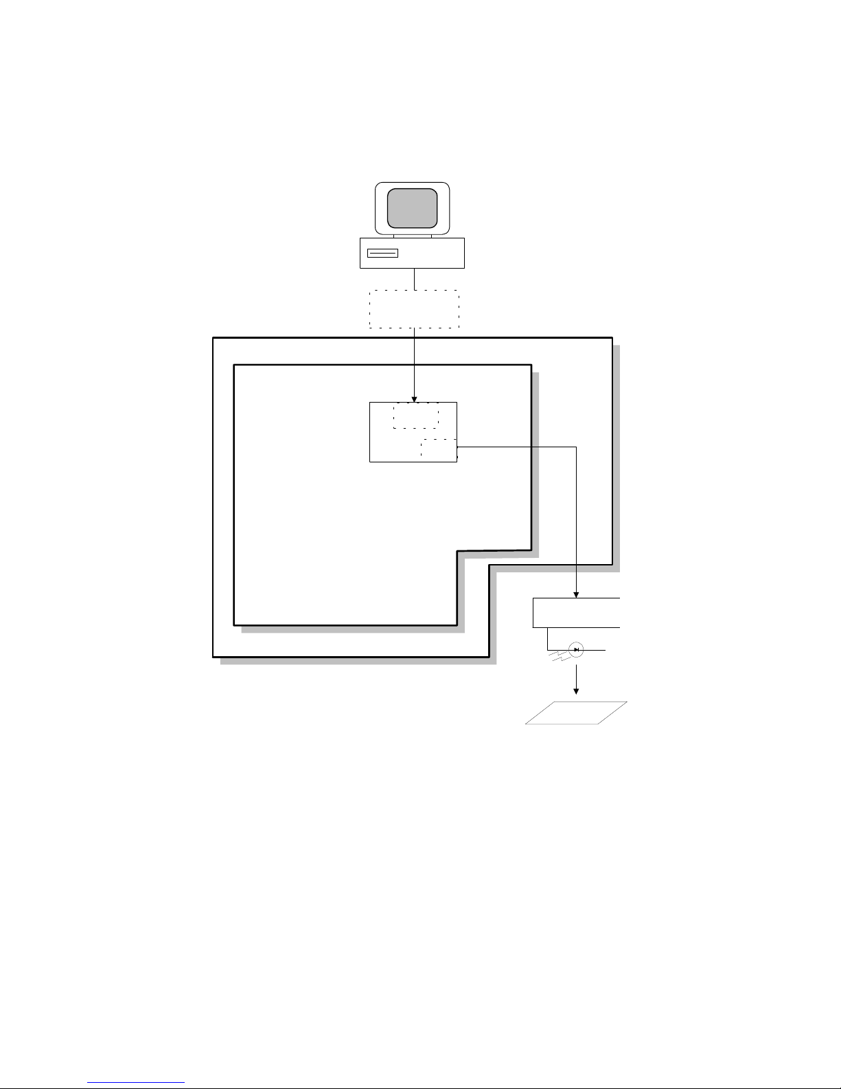
1.5.4. Printing using the Optional Printer Interface
After a page of data has been stored in the prin ter in te rfa ce’s page memory,
the data is sent directly to the LIF through the PRIF (Printer Interface) block.
FDU
FCE
LIF
FCIP
LDDR
Copy
Paper
PRIF
Optional Printer
Interface
PRIF: Printer Interface
LIF: Laser Interface
H521v512.wmf
OVERALL MACHINE INFORMATION May 22nd, 1995
VIDEO DATA PATH
1-18
Page 27
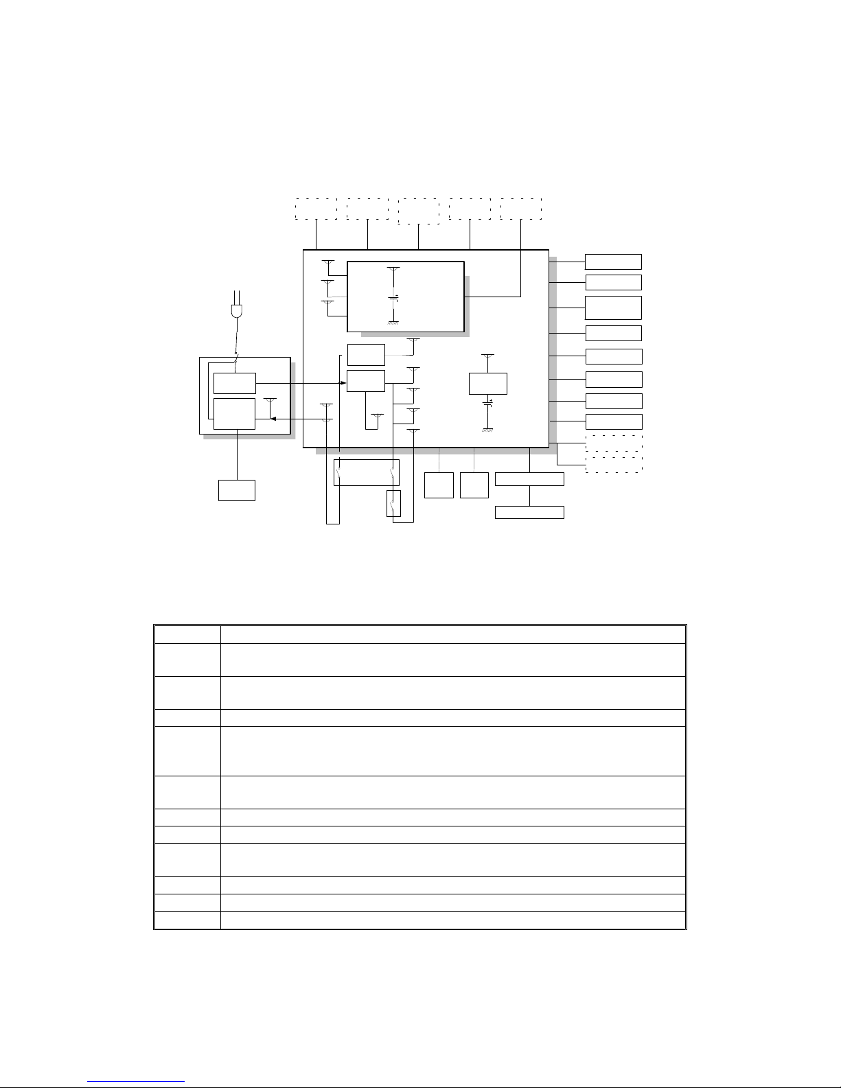
1.6. POWER DISTRIBUTION
1.6.1. Distribution Diagram
The PSU supplies +24V dc power to the FDU. The FDU converts the +24V
dc power supply to the following supplie s.
+5V This is normally on when the main switch is on.
+5VE
This is used for watching the activation signal when the machine is in energy
saving mode.
+5VLD
This supplies the laser diode. It is interrupted if the fusing unit cover interlock
switch opens.
+5VV This is a more stable power supply than +5V. It is used for the image sensor.
+5VD
This supplies the DRAM and the page memory card on the FCE to back up the
stored data for one hour, if the power is switched off and some data is stored in
them. A rechargeable lithium battery is used to generate +5VD.
+5VBAT
This supplies the system RAM on the FCE to back up the programmed data, if
the power is switched off. A lithium battery is used to generate +5VBAT.
+24V This is normally on when the main switch is on.
+24VD This is interrupted if the fusing unit cover interlock switch opens.
+24VIN
This supplies +24V to the fusing unit on/off switching circuit. It is interrupted if
the fusing unit cover interlock switch opens.
+24VM This is interrupted if the machine enters energy saving mode.
-5V This is used for the image sensor.
+12VP This is used for the page memory card.
+24VM
+5V
+5VV
-5V
+24V
+5VE
+5VLD
+5V
+5VE
Motors
Feed Clutch
Stamp
Cooling Fan
Ozone Fan
Power Pack
Thermistor
Printer Sensors
+24VM
+24VD
Optional
Counter
Optional 100
Sheet
Cassette
Optional
Printer I/F
Main Switch
+24VD
+24VD
+5V
+5V
+24VM
+5V
FDU
PSU
Fusing
Lamp
AC
Main
Power
AC Switching
Circuit
Interlock
Switch
LDDR
Image Sensor
Book Scanner
Operation Panel
NCU
+24VD
+24VM
+5V
+24V
+5V
+5VLD
+12VD
+5V
-5V
+5vv
+5VE
+5V
DC-DC
Converter
12VP
DC-DC
Converter
24VM
24VD
24VIN
Fusing Lamp
ON/OFF
Switching
Circuit
AC115V or 230V
+5VBAT
Optional
RS232C I/F
+5V
IC
Card
+12VP
+5V
+5VD
Xenon Lamp
+24VM
Optional ADF
+24VM
+5V
+5VD
+5V
DC-DC
Converter
+24VD
FCE
+24V
H521V510.wmf
May 22nd, 1995 OVERALL MACHINE INFORMATION
POWER DISTRIBUTION
1-19
Page 28
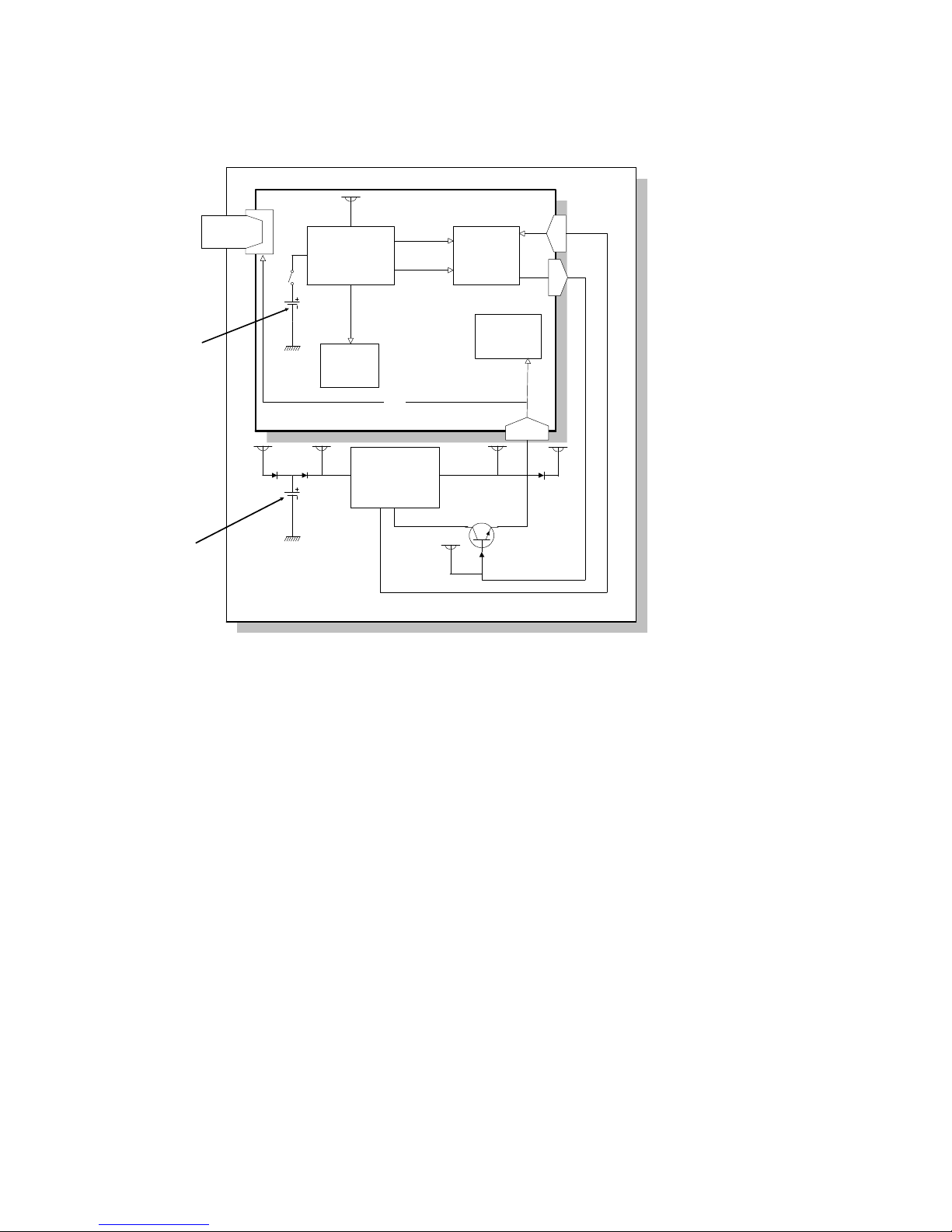
1.6.2. Memory Back-up Circuit
The +5VBAT supply from the lithium battery [A] backs up the system RAM
which contains system paramet ers an d pro grammed telephone numbers,
and the real time clock in the main cpu. The 5RTCCS sig na l tells th e ma in
cpu whether the back-up powe r (+5VB AT) is coming from the battery or from
the +5V power supply.
A rechargeable lithium batt ery [B ] an d the dc/ dc con verter on the FDU back
up the DRAM (SAF memory) for one hour, if there is data in the SAF memory
and the power is switched off. While the main power is on, the +5VE supply
recharges the batte ry. The battery recharges in o ne or two days.
The battery [B] generates ab out 3 volt s (max. 3. 2 vo lts). The dc/dc converte r
(IC12) lifts this voltage to 5 volt s so it can be used as the +5VD supply for
SAF backup. The CPU monitors the voltage of the +5VD sup ply with the
1VDET signal. When the battery has run down, and the volta ge is lower tha n
4.4 volts, the CPU stops the dc/dc converter by dropping 1SAFFG to low and
the machine stops backing up th e memo ry.
There is no battery switch for the battery [B].
FDU
FCE
FCIP
Switching
Circuit
System
RAM
DRAM
POWERS
5RTCCS
+5VBAT
+5V
+5VE
+5V
D
+5VD
1VDET
1SAFFG
CN1-92
CN1-94
CN1-96
Q5
+5VD
Page
Memory
DC/DC
Converter
[IC12]
+5V
+5V
+5VBAT
[A]
[B]
H521V511.wmf
OVERALL MACHINE INFORMATION May 22nd, 1995
POWER DISTRIBUTION
1-20
Page 29

2. DET AILED SECTION DESCRIPTIONS
2.1. SCANNER
2.1.1. Overview
1. Book Scanner
The scanner motor [A] drives th e scan ne r [ B] through the timing belt [C] and
drive wire [D]. The shaft [E] guide s sca nner movement in the sub-sca n direction. Inside the scann er [B ] are a contact image sensor (containing a sensor
element and xenon lamp) and a xenon lamp driver.
The scanner [B] consists of a contact image sensor and a xen on lamp driver.
The original width senso r [ F] an d len gth sensor [G] togeth er de te ct the size of
the original placed on the exposu re gla ss.
The scanner home position sensor [H] allows the scanner return to th e same
position after scanning.
The platen cover switch [I ] de te cts if the cover is opened or not.
[H]
[F]
[E]
[B]
[D]
[C]
[A]
[I]
[G]
H521D011.wm f
May 22nd, 1995 DETAILED SECTION DESCRIPTIONS
SCANNER
2-1
Page 30

2. ADF
The sheet through type ADF feeds th e docu men t from t he top page of t he
document stack on th e ta ble.
The pick-up [A] and feed roller [B] feed the original into th e scanner, and the
separation roller [C] help s to feed one sh eet at a time. Then, the R0 [D], R1
[E], and R2 [F] rollers feed the documen t th rou gh the scann er.
At the time of scannin g th e do cument, the scanner ([ B] on the previous page)
moves down to the scanning position under the exposu re g lass [ G] . The shading plate [H] pushes the docu ment to the exposure glass at the sca n line , so
that the document is with in th e image sensor’s range of focus.
After scanning, t he ADF f ee ds out the document o nto the platen cover, and
the scanner moves back to its home position at the right end of the scanner.
Unlike a copier’s ADF, this ADF does not have a document length sensor. So,
some of the copier features a re n ot ava ilable when the ADF is used. Ref er t o
“Original Detection - ADF” later in this chapter.
[A]
[B]
[C]
[D]
[E]
[G]
[F]
[H]
H521D008.wmf
DETAILED SECTION DESCRIPTIONS May 22nd, 1995
SCANNER
2-2
Page 31

2.1.2. Original Detection
1. Book Scanner
The original width and length senso rs each have two sets of photoemitter
and receiver. The actual detection points on the exposu re g lass a re W1, W2,
L1 and L2 in the diagram. The cpu continuou sly che cks th e se nso r ou tp ut s
when the platen cover is open. The machine uses the paper size detected
just before the plate n cover is closed (or before pressing the Sta rt key if the
platen cover is kept open). The ta ble below shows the paper size de te cted for
each set of sensor outpu ts, and the data width selected for a fax transmission.
Sensor Outputs
USA Europe and Asia Data Width in Fax Tx
W1 W2 L1 L2
0 0 0 0 B4 Lengthwise B4 Lengthwise 256 mm
0101
Letter Lengthwise
(Note 1)
A4 Lengthwise
(Note 1)
216 mm
1 1 0 1 B5 Lengthwise B5 Lengthwise 216 mm
0 0 1 1 B5 Sideways B5 Sideways 256 mm
0111
Half-Letter Sideways
(Note 1)
A5 Sideways
(Note 1)
216 mm
0100
Legal Lengthwise
(Note 1)
F/F4 Lengthwise
(Note 1)
216 mm
1111
Size not detected
(Note 2)
A5 Lengthwise or
Size not detected
(Note 3)
216 mm (US)
216 or 256 mm (Other)
(Note 4)
Sensor output: 0 = Original present; 1 = Original not present
B4
A4/Letter
B5
A5/Half Letter
W1
W2
L1L2
B5 Sideways
B4 F A4 B5 A5
A5
B5
F
A4
B4
224.4
192.9
8
1/2
5
1/2
1114
306.2
243
Original Width
Sensor
Legal
Original Length
Sensor
H521D502.wmf
May 22nd, 1995 DETAILED SECTION DESCRIPTIONS
SCANNER
2-3
Page 32

Notes
1. The setting of System Switch 0D det ermin es which paper size is detected
(USA standard or ISO standard) f or each sensor output combination.
However, changing a setting will cause some copier functions to not work
correctly. (For example, if A4 is selected in the USA model, automatic paper select does not work. This is be cau se A 4 size pape r is no t available
for printing with the USA model.)
2. USA: For both Fax and Copier operations, the machine will ask the user
to choose a scanning area which is equiva lent to Half-letter sideways, Letter, or Legal.
3. If bit 4 of System Switch 0D is 0, the machine uses A 5 le ng th wise for copier operations (e.g. , e nla rgement to A4 size using a fixed zoom rate). But ,
in Fax mode, the machine will ask the user to choose a scanning area
which is equivalent to an available orig inal size.
If bit 4 of System Switch 0D is 1, the machin e will ask the user to choose
a scanning area which is equivalent to an available origina l size, for both
Fax and Copier operations.
4. The following table shows which data width is use d dep ending on what
original size the user has selected.
Data Width Original Size Selected
216 mm Letter, Legal, Half-letter sideways (US)
F/F4, A4, B5 lengthwise, A5 sideways
(Europe/Asia)
256 mm B4, B5 sideways
DETAILED SECTION DESCRIPTIONS May 22nd, 1995
SCANNER
2-4
Page 33

2. ADF
When using the ADF, the machine can only detect the docume nt width. Unlike a copier’s ADF, the machine cannot detect the d ocu ment length, because
there is no length sensor.
As a result, the followin g cop ier functions cannot be used when using the
ADF, since these functions req uire the document lengt h be fo re proceeding.
• Automatic paper selection
• Erase border/center
The document sensor [ A] and B4 widt h sensor [B] detect the document width.
• When the document sensor is activate d but the B4 width sensor is not,
the machine treats the document widt h as eit her A4 (21 0 mm) or Le tter/Legal (216 mm).
• When both sensors are activated, the ma chin e treats the document
width as B4 (256 mm).
The setting of system switch 0C bit 3 determines whether an International or
US paper size is detected.
[B]
[A]
H521D006.wmf
May 22nd, 1995 DETAILED SECTION DESCRIPTIONS
SCANNER
2-5
Page 34

2.1.3. Scanning
1. Contact Image Sensor
The contact image sensor (CIS ) assembly [A] consists of an exposure glass
[B], a roof mirror lens array [C], a xenon lamp [D] , an d an image senso r [ E] .
The CIS moves under the expo sure glass when scanning a book origina l, or
stays at the ADF scan line when scanning a shee t original using the ADF.
The image sensor is a row of 4096 photosensitive elements (B4 width x 16
dots/mm). The roof mirror lens array focuses the light reflected fro m the document onto the image sen sor.
Because of the short op tica l path inside the CIS, the fo cal de pt h is mu ch
shorter than for a CCD type scanner. Because of this, two springs at each
end of the CIS push it against the exposure glass [F], so that the distance
from the original is kept the same all the time. However in book scanning
mode, if the original is out of the CI S’s focal range, the scan ne d image may
get darker.
Because the analog out pu t sign al is a sawto oth waveform, data samplin g timing should be adjusted when ever a new CIS is installed in the mach ine . Refer
to section 5.2.1 for more details.
[C]
[E]
[D]
[A]
[F]
[B]
H521D512.wmf
DETAILED SECTION DESCRIPTIONS May 22nd, 1995
SCANNER
2-6
Page 35

2. Main Scan Resolution and Width (Book Scanne r)
Fax Mode
B4 (256 mm/10.1" width) Original
The machine scans 256 mm (10. 1") wid th at 16 dot /mm reso lution, then
convert it into 8 dots/mm resolu tio n be fo re transmission.
A4 (210 mm/8.3")/ Letter (216 mm/8.5") Original
The machine scans either 216 mm (8.5" ) or 210 mm (8.3" ) width at 16
dot/mm resolution, de pend ing on the settings of Syste m Switch 0D bits 0 to
5, then converts the data into 8 dot/mm resolution bef ore transmission. However , the original width of the A4/Lett er size specified in the T.30 protocol is
216 mm. So, the following diagrams exp lain the actu al scan ne d widt h in ea ch
paper size.
Letter size:
The machine scans and
transmits the whole
width of the original.
A4 size:
The machine scans 213
mm from the front end
of the scanning are a,
and adds 3 mm of white
data at the beginning of
each line to get a 216
mm width of data for
transmission.
Copy Mode
The machine scans 256 mm (B4 widt h) at 16 d ot /mm re solution. Then, ea ch
scanned line is stored in the page memory for printing.
A4
(210 mm width)
AA
AA
A
AA
A
AA
A
AA
A
AA
A
AA
A
AA
A
AA
A
AA
A
AA
A
AA
A
AA
A
AA
A
AA
A
AA
A
AA
A
AA
A
AA
A
AA
A
AA
A
AA
A
AA
A
AA
A
AA
A
AA
A
AA
A
AA
A
AA
A
AA
A
AA
A
AA
A
AA
A
AA
A
AA
A
AA
A
AA
A
AA
A
AA
A
AA
A
AA
A
AA
A
AA
A
Scan Width (210 mm)
Transmitted Data Width
(216 mm)
Added Data (3 mm)
Scanned Data
(213 mm)
Letter/Legal
(216 mm width)
AA
A
AA
A
AA
A
AA
A
AA
A
AA
A
AA
A
AA
A
AA
A
AA
A
AA
A
AA
A
AA
A
AA
A
AA
A
AA
A
AA
A
AA
A
AA
A
AA
A
AA
A
AA
A
AA
A
AA
A
AA
A
AA
A
AA
A
AA
A
AA
A
AA
A
AA
A
AA
A
AA
A
AA
A
AA
A
AA
A
AA
A
AA
A
AA
A
AA
A
AA
A
AA
A
AA
A
AA
A
AA
A
AA
A
Scan Width (210 mm)
Transmitted Data Width
(216 mm)
Scanned Data
(216 mm)
H521D503.wmf
May 22nd, 1995 DETAILED SECTION DESCRIPTIONS
SCANNER
2-7
Page 36

3. Main Scan Resolution and Width (ADF)
Fax Mode
• The machine scans either 216 mm (A4/Lette r) or 256 mm (B4) a t 16
dot/mm resolution, depen ding on the document width detected. Then
each line is converted into 8 dot/mm resolution before transmission.
Copy Mode
• The machine scans the document width at 16 dot /mm reso lution.
4. Sub Scan Resolutions and Length (Book Scanner)
Fax Mode
• The machine scans at 15.4 lines/mm, then it convert s the re solu tio n be -
fore transmission if necessary (refe r to “Su b Scan Resolution Conversion” later in this chapter). The scan length is the le ng th of the original
detected by the original length sensors (refer to "Original Detection ").
Copy Mode
• The machine scans the number of lines required for printing. For exam-
ple, to print an A4 size copy, 292 x 15.4 lines are scanned (292 mm =
A4 length less the top and bottom margin s of 2 mm each - the margins
are adjustable by RAM address).
Sub scan resolution depe nd s on th e selected reproduction ra tio . It is
controlled by the mot or speed, and not by ima ge processing. At high er
motor speeds, more scan lines are omitted, and the effect of this is a
lower reproduction ratio. There is a ran ge of reso lut ions from 2.82 s per
A4 page (3.85 lines/mm) for a 50% reproduction ratio up to 11.3 s per
page (15.4 lines/mm) for 200%. See "Drive Mech an ism" fo r how th e motor speed varies with reproduct ion ratio.
5. Sub Scan Resolutions and Length (ADF)
Fax Mode
• The machine scans at 15.4 lines/mm, then it con verts the resolution for
transmission if necessary (refer to “Su b Sca n Reso lut ion Conversion”
later in this chapter).
The machine scans the full document length except for the top and bottom margins. However, the length should not exceed the maximum
length programmed by Scan ne r Sw itch 00, bits 2 an d 3.
Copy Mode
• See "Sub Scan Resolutions and Length (Bo ok Scanner)" above.
If the original is longer than the paper length, the excess part is lost.
DETAILED SECTION DESCRIPTIONS May 22nd, 1995
SCANNER
2-8
Page 37

6. Sub Scan Resolution Conversion
Since the scanner always scans at 15.4 line /mm reso lution, sub scan resolution has to be converted when tran smitt ing to a termina l wh ich is not capable
of higher resolutions.
Standard: The first and third lines in each four-line group are OR proce ssed
for transmission. Other lines are deleted .
Detail: Pairs of lines are OR processe d fo r t ran smission .
Fine: All the scanned lines are transmitted.
In memory transmission, if the ot her t ermin al cannot receive a message at
Fine resolution, alternate lines (even-numbered lines) are deleted be fore
transmission.
Cut
Cut
OR
Processing
3.85 l/mm
Transmit
AAAA
AAAA
AAAA
AAAA
AAAA
AAAA
AAAA
AAAA
AAAA
AAAA
AAAA
AAAA
AAAA
AAAA
AAAA
AAAA
AAAA
AAAA
AAAA
AAAA
AAAA
AAAA
AAAA
AAAA
A
A
A
A
A
A
A
A
Feed
1st Line
2nd Line
3rd Line
4th Line
15.4 l/mm
15.4 l/mm
15.4 l/mm
15.4 l/mm
H521D513.wmf
Transmit
OR
Processing
Feed
OR
Processing
7.7 l/mm
7.7 l/mm
1st Line
2nd Line
3rd Line
4th Line
AAAA
AAAA
AAAA
AAAA
AAAA
AAAA
AAAA
AAAA
AAAA
AAAA
AAAA
AAAA
AAAA
AAAA
AAAA
AAAA
AAAA
AAAA
AAAA
AAAA
AAAA
AAAA
AAAA
AAAA
A
A
A
A
A
A
A
A
15.4 l/mm
15.4 l/mm
15.4 l/mm
15.4 l/mm
H521D514.wmf
Transmit
AAAA
AAAA
AAAA
AAAA
AAAA
AAAA
AAAA
AAAA
AAAA
AAAA
AAAA
AAAA
AAAA
AAAA
AAAA
AAAA
AAAA
AAAA
AAAA
AAAA
AAAA
AAAA
AAAA
AAAA
AAAA
AAAA
AAAA
AAAA
Feed
1st Line
2nd Line
3rd Line
4th Line
15.4 l/mm
15.4 l/mm
15.4 l/mm
15.4 l/mm
15.4 l/mm
15.4 l/mm
15.4 l/mm
15.4 l/mm
H521D515.wmf
May 22nd, 1995 DETAILED SECTION DESCRIPTIONS
SCANNER
2-9
Page 38

2.1.4. Drive M echanism
1. Book Scanner
The book scanner motor [A] drives the scanner [B] thro ug h th e timing belt [C]
and drive wire [D]. The scanner moves alon g t he gu ide shaft [E].
The spring [F] pushes up the cont act image sensor [G] to the exp osure glass,
so that the distance fro m t he ima ge senso r t o th e exposure glass surface is
constant during scanning.
The motor speed depends on the select ed resolution. For referen ce, the following table shows the sp ee d f or sca nn ing an A4 size original.
• Fax mode
Standard 5.65 s
Detail 5.65 s
Fine 11.30 s
•
Copy Mode
Reduction Scan Speed (/A4)
Full Size and
Enlargement
Scan speed (/A4)
50 % reduction 2.82 s Full size 5.65 s
65 % reduction 3.67 s 115 % 6.50 s
71 % reduction 4.01 s 121 % 6.84 s
74 % reduction 4.18 s 122 % 6.89 s
77 % reduction 4.35 s 141 % 7.97 s
82 % reduction 4.63 s 155 % 8.76 s
87 % reduction 4.91 s 200 % 11.30 s
93 % reduction 5.25 s
[A]
[D]
[C]
[E]
[B]
[F]
[G]
H521D012.wmf
DETAILED SECTION DESCRIPTIONS May 22nd, 1995
SCANNER
2-10
Page 39

2. ADF
The ADF motor [A] drives the pick-up rolle r [B], the feed roller [C], the R0
roller [D], the R1 roller [E], and the R2 roller [F].
The motor speed varies in the same way that the book scanner motor does
(see the previous page).
Cross reference
Maximum document length: Scanner Switch 00, bits 2 and 3.
[A]
[B]
[C]
[D]
[E]
[F]
H521D005.wmf
May 22nd, 1995 DETAILED SECTION DESCRIPTIONS
SCANNER
2-11
Page 40
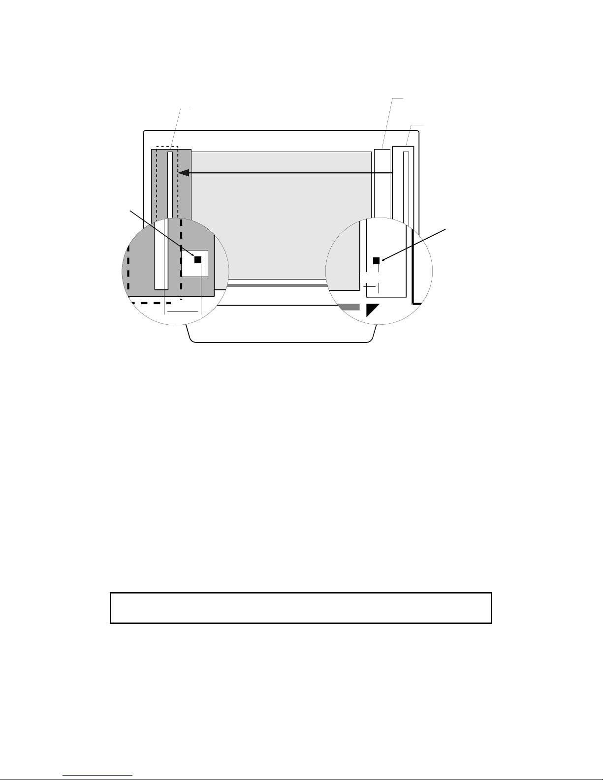
3. Scanner Position Fine Adjus tme nt
T wo square black marks [A] and [B] (2 x 2 mm) are used to move the scanner
to the exact scan sta rt p osition. At the start o f scanning, the scanne r move s
from the scanner home posit ion, and looks for the appro pria te mark, which
depends on the scanning mode (book or ADF). The ma chine uses the black
mark to move to the exact scan start posit ion , which is nearb y.
• Book Scanner
When the machine detect s t he right edge of the black mark [A], it moves
another 4 mm to the sca n sta rt po si tio n.
• ADF
When the machine detect s t he right edge of the black mark [B], it moves
another 54 mm to the scan start posit ion.
If the black mark cannot be found, scanning cont inues, but error code 1-09 is
generated and stored in the error cod e memo ry area .
Cross-reference
Image Adjustment: Section 5.11
Exposure Glass
ADF Scan Line
Shading Plate
Scanner at
Home Pos ition
54mm
4mm
[B]
[A]
H521D521.wmf
DETAILED SECTION DESCRIPTIONS May 22nd, 1995
SCANNER
2-12
Page 41

2.1.5. Pick-up and Feed (ADF)
When the ADF motor starts, the mechanical clutch [A] moves the pick-up
roller [B] down to the document. Then, th e machine feeds the top pa ge of the
document. After the last page is scanned, th e ADF mot or reverses brie fly to
move the pick-up roller back to the standb y posit ion.
2.1.6. Separation Mechanism (ADF)
The feed roller [A] and th e separation roller [B] preve nt more than one sheet
of paper from feeding into the scanner at once .
When the feed roller feeds a sheet of paper, both the feed and the separation
rollers rotate in the feed-in dire ctio n. However, if two or more sheets are between these rollers, the separat ion roller rotates in the feed-out dire ctio n to
prevent the lower sheet from being fed into the scanner.
Cross reference
Separation mechanism: Group 3 Facsimile Manual, page 2-2-14.
H521D009.wmf
[A]
[B]
H521D007.wmf
[A]
[B]
H521D511.wmf
May 22nd, 1995 DETAILED SECTION DESCRIPTIONS
SCANNER
2-13
Page 42
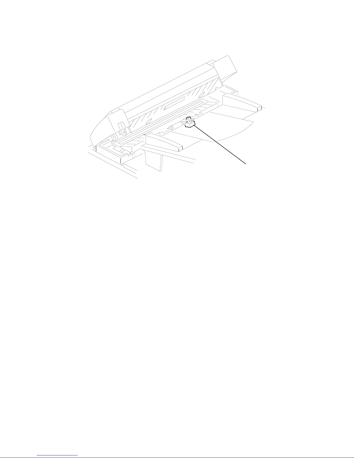
2.1.7. Stamping (ADF)
The machine always stops feed ing at the stamping position.
If the Stamp LED is turn ed on, the machine activates the stamper solenoid
[A] for 500 ms after the page was transmitted (immediate tran smission ) or
stored (memory transmission) successfully. Then the page is fed out of the
scanner.
If the Stamp LED is turn ed off, the machine feeds ou t the page without stamping.
[A]
H521D010.wmf
DETAILED SECTION DESCRIPTIONS May 22nd, 1995
SCANNER
2-14
Page 43

2.1.8. Error Conditions
1. Book Scanner
The main cpu detects an error if one of the follo wing cond itio ns occurs.
Condition Description Error
Code
Black mark not detected
The scanner did not detect the black mark at
scanning start position correction. The machine
does not stop scanning even if this error was
detected.
1-09
Incorrect home position
sensor condition
The scanner home position sensor did not turn on
after the motor moved 480 mm back to the home
position after scanning.
9-11
The scanner home position sensor stayed on after
the motor moved 20 mm from the home position at
the start of scanning.
The scanner could not go to the home position at
power on.
Cover open
While the machine is working, the printer cover is
open and the interlock switches turn off.
No error
code
2. ADF
The main cpu detects an error if one of the follo wing cond itio ns occurs.
Jam Condition Description Error
Code
Non-feed
The scan line sensor does not switch on within
3.7 s of the ADF motor starting.
1-00
Incorrect sensor
conditions
The scan line sensor switches on while the
document sensor is off.
The document width sensor switches on while the
document sensor is off.
The scanner home position sensor did not turn on
after the motor moved 480 mm back to the home
position after scanning using ADF.
9-11
Maximum document
length exceeded
The scan line sensor does not turn off after the
maximum document length has been fed since it
turned on; this is after 23 s at standard and detail
resolution, or 46 s at fine resolution (these times
are for a 1.2 m long document).
1-01
Black mark not detected
The scanner does not detect the black mark at
scanning start position correction. A document jam
is not detected for this error code, and scanning
continues as normal.
1-09
May 22nd, 1995 DETAILED SECTION DESCRIPTIONS
SCANNER
2-15
Page 44

Jam Condition Description Error
Code
Error during feed-out
When the final page of the document has been
fed out of the scanner, or when a jammed
document has been removed, the ADF motor
reverses. The error occurs if a document is placed
into the feeder while the motor is rotating.
No error
code
Cover open
While the machine is working, the ADF cover
and/or printer cover are open.
No error
code
DETAILED SECTION DESCRIPTIONS May 22nd, 1995
SCANNER
2-16
Page 45

2.1.9. Video Processing
1. Analog Signal Processing
The analog video signal fro m the cont act image sensor assembly is amplified
in the FDU, then transferred to the DI P (Digital Image Processor) inside th e
FCIP.
FDU
FCE
FCIP
DIP
Original
Xenon Lamp
Amplifier
Analog data
Video SRAM
(VRAM)
Binary
data
Image
Sensor
Contact Image Sensor Assembly
H521D519.wmf
May 22nd, 1995 DETAILED SECTION DESCRIPTIONS
SCANNER
2-17
Page 46

2. Digital Video Processing Steps
Overview
The analog signal from the CI S is first con verted into an 8-bit digital signal.
Then it passes through some digit al processes that depend on the selected
scanning modes. To process the dat a, the DIP uses a dedicated 8 kb video
SRAM (VRAM).
From Image Sensor From thermistor
Dither matrix process
Auto density control
MTF
Thresholding
Erasure of irregular
dots
OR processing
A/D Conversion
Video Signal Correction
-Auto Shading
(all-black and all-white signal correction)
-Peak Hold
Halftone?
Gamma Correction
Edge detection
Error diffusion
process
Edge
enhancement
Output
Start scanning
Multiplexer
YES
NO
COPY
FAX
Analog
Digital
Reduction?
Main Scan Reduction
Mode?
NO
YES
Reduction?
Main Scan Reduction
NO
YES
Scanner Position
Fine Adjustment
AAAA
AAAA
AAAA
AAAA
AAAA
AAAA
AA
AA
AA
Standard resolution
15.4 l/mm
15.4 l/mm
15.4 l/mm
15.4 l/mm
3.85 l/mm
1st Line
2nd Line
3rd Line
4th Line
AAAA
AAAA
AAAA
AAAA
AAAA
AAAA
AA
AA
AA
Detail resolution
1st Line
2nd Line
3rd Line
4th Line
7.7 l/mm
7.7 l/mm
15.4 l/mm
15.4 l/mm
15.4 l/mm
15.4 l/mm
Conversion
to
6-bit data
Thresholding
HALFTONE PROCESS
Error diffusion
process
Dither matrix process
HALFTONE RESOLUTION
CONVERSION
*
Background
detection
H521D520.wmf* In fax mode, if halftone is selected at standard or detail resolution,
sub scan resolution is converted as shown in the diagram, before any
digital image processing is done.
DETAILED SECTION DESCRIPTIONS May 22nd, 1995
SCANNER
2-18
Page 47
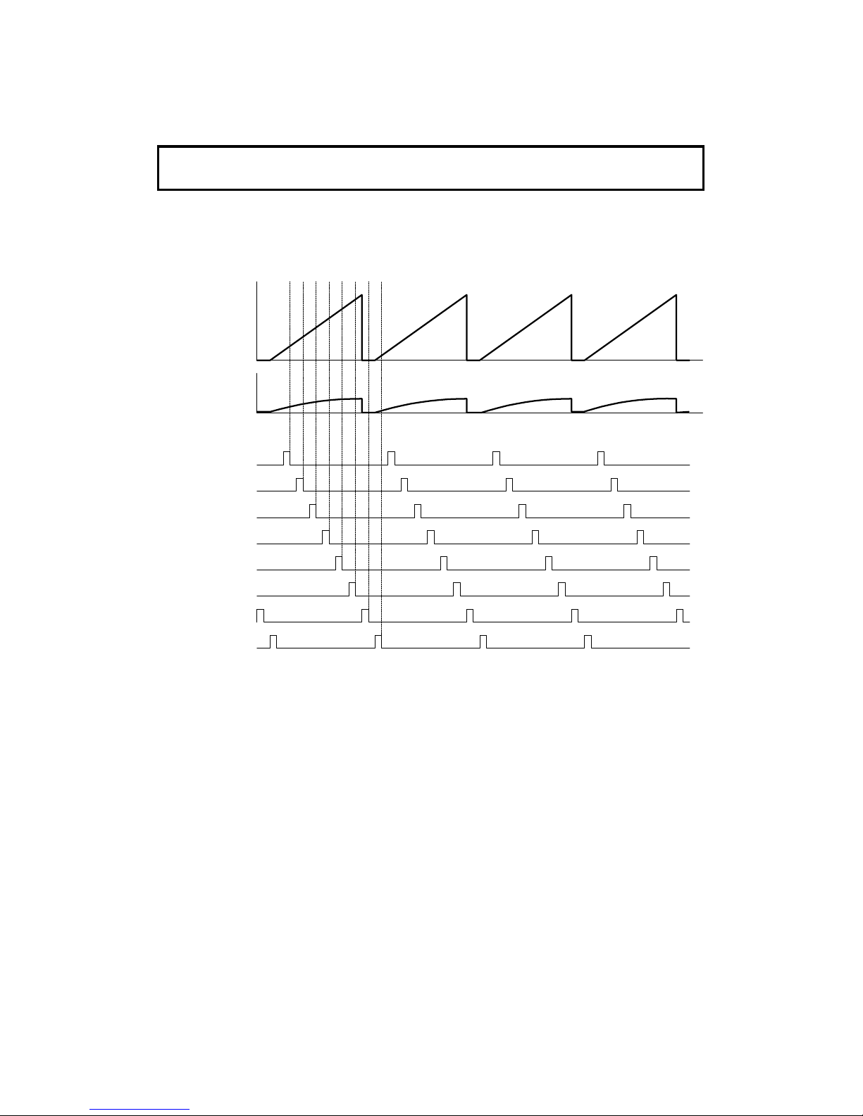
Details
Cross-reference
Group 3 Facsimile Manual: section 2-3
The DIP carries out the following image pro cessin g on the data (ref er to the
flow chart on the previous page).
Sampling Clock Selection
The image sensor output is a sawtooth wavef orm. So the sensor output level
depends on the sampling clock sele cte d as shown in the above diagram.
The clock is adjusted at the factory. But in the field, the clock should be reset
using service function 10-4 whenever the image sensor is replaced. Refer to
section 4.1.19 for the procedure.
Scanner Lamp ON
Scanner Lamp OFF
Clock 0
Clock 6
Clock 7
Clock 5
Clock 4
Clock 3
Clock 2
Clock 1
H521D510.wmf
May 22nd, 1995 DETAILED SECTION DESCRIPTIONS
SCANNER
2-19
Page 48

Preliminary Processing
1. A/D conversion
• The multiplexer selects the data from th e image sensor, then the DIP
converts this to an 8- bit digital signal.
2. Video signal correction
• The image sensor corrects for the gound level and amplification ratio by
itself.
• The machine reads all-black and all-white waveforms before the scan-
ner moves to scan the document.
First, the image sensor reads the white plat e that is behin d the
exposure glass, with the lamp off. The machine stores the output data in
the VRAM (this is the all-black waveform). The image sen sor t hen re ads
the white plate with th e lamp on, and the machine stores th is dat a (this
is the all-white waveform).
Then, the machine starts scanning the document . Th e d ata output from
each element on the image sensor is compared with the above stored
values, and corrected (t his is Auto shading).
• The all-white waveform is also used as a peak level for the pe ak ho ld
function.
If Halftone was not selected
1. Background detectio n
• Each pixel is tested in relation to its neighbours to determine if it is back-
ground noise and should be eliminated.
2. Auto density control
• The most suitable threshold value is calculated from the density th at is
detected from a fixed area on each original.
3. MTF
MTF (Modulation Transfer Function) can rep rod uce details such as thin lines,
points, and complex characters.
4. Thresholding
• Each video data element is compared against the thre sho ld level, which
depends on the contrast sele cted by the user. If an element is lighter
than the threshold level, it is conve rted to a white (0). Otherwise, it becomes a black (1).
5. Erasure of irregular dots
DETAILED SECTION DESCRIPTIONS May 22nd, 1995
SCANNER
2-20
Page 49
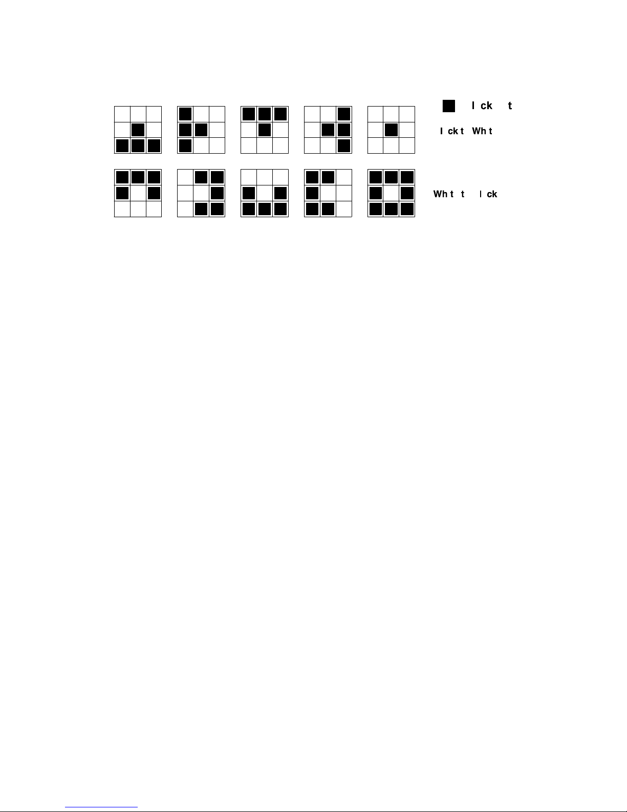
• If an element after being converte d to white or black by th e ab ove thre -
sholding is irregular against the surrounded pixels, it is output in the opposite color. The central pixel is compared with the surrounding eig ht
pixels to determine whether this pro cess is ne cessa ry. There are ten
cases, as shown below, in which conversion is done. This results in a
noise-free and clean image.
5. OR processing
• When the user selects a resolution that is less than the reso lut ion used
by the scanner, the DIP will either do OR processing and/or skip alternate lines of data to conve rt th e scanned resolution into the re solu tion
required for transmission. (See "Sub Scan Resolution Con versio n" in
section 2-1-1.)
If Halftone was selected
1. Gamma correction
• Gamma correction corrects the response of the imag e sen sor to the vari-
ous shades in the gray scale from black to white.
2. Edge detect ion
• Edge detection preserves the sharp ne ss of image outlines. Each ele-
ment is tested to determine whethe r it is on a boundary of two are as of
sharp contrast.
H521D522.wmf
May 22nd, 1995 DETAILED SECTION DESCRIPTIONS
SCANNER
2-21
Page 50

3. Halftone process
• The data is converted to six-bit (0 - 63) for halftone processing. In addi-
tion, if error diffu sion was se lect ed , each element is corrected using the
differences between it and the surrounding ele men ts. This process reduces the diffe ren ces in contrast between light and dark areas of a halftone image.
• Edge enhancement is done - As a result of the ed ge detection, if the ele-
ment is on a boundary, the element goes directly to white or black, without thresholding (see below).
• The data is thresholded. Each pixel is compared with the corresponding
element in a dither matrix or using erro r diffusion. The resulting data is
one-bit (0 or 1).
3. Video Processing Parameters
Some of the paramete rs used for digital image processing can be chan ge d
by RAM addresses. See section 5-11-4 for details.
1. Contrast
RAM addresses 8003FD to 80040E
2. Image processing parameters
RAM addresses 80040F to 800426
DETAILED SECTION DESCRIPTIONS May 22nd, 1995
SCANNER
2-22
Page 51

2.2. PRINTING
2.2.1. Printing Process - Overview
This machine uses a "write to black" syste m, usin g ne gative toner.
• The charge corona wire gives the drum surface a negative cha rge of
-750 V.
• The exposed area on the drum drops to about -100 V.
• The development roller carries toner to the latent image on the drum sur-
face.
Development bias (during prin ting):
Toner application roller : -700 V
Development roller: -400 V
Switching bias:
Toner application roller : -50 V
Development roller: +250 V
• The transfer roller pulls the toner from the drum onto the paper.
A constant current of +5 µA is applied. The antistat ic brush helps to
separate the paper from the drum.
• The cleaning blade removes any tone r remaining on the drum after th e
image is transferred to th e pape r.
• The quenching lamp reduces the negative charge on the drum to about
-50 V.
H521D637.wmf
May 22nd, 1995 DETAILED SECTION DESCRIPTIONS
PRINTING
2-23
Page 52

2.2.2. OPC Drum
An organic photoconducto r drum [A] is used in this machine. The diameter of
the drum is 30 mm. It is driven by the main motor [B] through a gear train.
The toner application roller [C] , de velo pment roller [D], and transfer rolle r [E]
are also driven by the same gear train. The dru m u nit is rep laceable by the
customer.
2.2.3. Charge
The CTM contains a charge coro na unit . The corona wire [A] generates -ve
ions when the power pack [B] applies a consta nt curren t of -305 ± 5 µA (the
voltage is about -5.3 kV) . The grid plate [C] en sure s tha t t he charge is uniformly spread out. The zener d iod e [D] ensures that the cha rge on the drum
does not exceed -750 ± 50 V.
The charge corona unit contains a wire cleaner [E] for use r ma int en an ace .
The ozone fan on the left ha nd side of the machine provides air flow to the
charge corona unit, an d th e ozone filter (a paper filter coa te d with carbon) decomposes the ozone gen era ted around the drum by t he corona discharge.
[B]
[C]
[A]
[E]
[D]
H521D604.wmf
[E]
[D]
[B]
[A]
[C]
H521D605.wmf
DETAILED SECTION DESCRIPTIONS May 22nd, 1995
PRINTING
2-24
Page 53

Charger Leak Detection:
The machine detects a charger leak error when the FDU CN21-8 stays low
for 3 seconds or more (6 seconds or more at powe r on) eit he r while in
standby mode or while the corona wire is being charged. When this occurs,
the machine warns the customer by ligh ting the Call Service indicator (error
code 9-17).
Charge Control
In this machine, a higher corona wire current is used to counter black bands
on copies. The charge on th e dru m exceeds the zener diode volt ag e a s a result of this higher current.
Power
Pack
Driver
EXIO
CPU
1-43
21-1
Power
Pack
21-3
21-8
-715V
24VM
Leak Signal
Charge
Fusing Unit Cover
Interlock Switch
ON/OFF
IC8
IC4
FCE
FDU
H521D657.wmf
May 22nd, 1995 DETAILED SECTION DESCRIPTIONS
PRINTING
2-25
Page 54

2.2.4. Laser Exposure
1. Overview
The components of the laser section are the same as those described in the
section 4-3-3 of the Group 3 Facsimile manual. The drum [A] is positioned in
the same plane as the laser unit, so there is no mirror to chan ge the opt ical
path.
Points to note:
• The focusing lens [B] is a barrel toroidal lens.
• The shield glass [C] prevents toner and dust from en te ring the laser op-
tics area.
• An optical fiber [D] passes the reflected laser beam to the laser sychro ni-
zation detector circuit in the FDU.
• The shape of the mirror [E] is hexagonal.
• The strength of the beam emitted from the LD unit [F] is 5 mW at a
wavelength of 780 nm.
• The dimensions of the dot on the drum are 85 µm by 85 µm.
The hexagonal mirror motor speed dep ends on the print ing resolution:
• Copy and G3 l/mm mode (16 x 15.4 dots/mm): 10402 rpm
• Printer mode (300 dpi): 7977.8 rpm
The charge on the exp ose d section of the drum drops to about -100 V while
non-exposed areas it rema ins at abo ut -750 V.
Cross-reference
Group 3 Facsimile Manual: section 4-3-3
[E]
[D]
[B]
[C]
[F]
[A]
H521D606.wmf
DETAILED SECTION DESCRIPTIONS May 22nd, 1995
PRINTING
2-26
Page 55

2. Block Diagram
The LIF block in the FCIP monitors and controls the laser diode power (FDU
CN26-2) and transfers data fo r printing to the laser diode (FDU CN26-4 ).
Cross-reference
Group 3 Facsimile Manual: page 4-3-13
3. Error Conditions
LD Failure Detection:
The machine detects LD f ailu re when the Laser Synchroniza tio n signal is not
detected within 10 ms of the LD ready signal. When this occurs, the machine
warns the customer with th e Call Service indicator (error code 9-20).
Mirror Motor Error:
The machine detects a mirror moto r error when FDU CN14-4 does not go low
within 10 seconds of the hexagonal mirror motor being turned on.
The machine also detects a mirror motor error when FDU CN14-4 goes back
to high for 3 seconds or more during mirror motor op era tion. When either of
these errors occurs, the machine warns the customer with the Call Service indicator (error code 9-23).
FDU
FCE
LDDR
FCIP
Laser
Synch
Detector
Circuit
1-37
1-36
1-40
1-91
1-1114-4
14-3
EXIO
CPU
LIF
LD Enable
DATA
Control
Laser Synch
Detector
Mirror Motor Lock
Laser
Diode
Laser
Diode
Controller
Hexagonal
Mirror
Drive Unit
Mirror Motor Enable
26-6
26-4
26-2
1-2
1-4
1-6
H521D648.wmf
May 22nd, 1995 DETAILED SECTION DESCRIPTIONS
PRINTING
2-27
Page 56

4. Print Density Adjustment
The FCIP controls print image density by changin g th e laser pulse width to
adjust the width of the dot s across th e pa ge . The beam strength is not a djusted in this model.
The following table shows th e relationship between the pulse wid th and the
image density.
Mode
Image Density
Normal Lighten Darken
Copy
Mode
Normal 80 % 40 % 160 %
Halftone 80 % 40 % 160 %
Enlarge
in
Copying
115 %
Normal 100 % 40 % 160 %
Halftone 80 % 40 % 160%
122 %
Normal 100 % 50 % 150 %
Halftone 83 % 50 % 150 %
141 %
Normal 100 % 43 % 157 %
Halftone 86 % 43 % 157 %
200 %
Normal 100 % 40 % 160 %
Halftone 80 % 40 % 160 %
Fax
Mode
Normal 100 % 40 % 160 %
Halftone 20 % 20 % 100 %
To change the pulse width, the dut y cycle of th e laser pulse is changed. For
example, to make the print density 40% of norma l, the laser is only kept on
for 40% of the normal dura tio n for each pixel.
5. Enlargement
For enlargement, the FCIP controls the magnification ratio by changing the interval between pulses in the lase r clo ck signa ls. So, for example, the clock
signal pulse interval for 200% enlargement is twice as long as the interval for
normal (100%) image reproduction. This makes each image pixel for 200%
enlargement become twice as long as each pixel for normal image reprod uction.
During copying, a main scan resolu tion of 16 dots/mm is used, and smoothing is not done on images of this resolutio n. In enlargement, since each pixel
is enlarged, video processin g such as smo ot hing cannot be done.
DETAILED SECTION DESCRIPTIONS May 22nd, 1995
PRINTING
2-28
Page 57

6. Toner Saving Mode
In this machine, toner savin g is d on e by red ucin g the number of dots actually
printed, not by varying the de velopment bias. In toner sa ving mode , the image data is filtered through the following four-line mat rix.
1st line 1 0 1 0 1 0 1 0 1 0 . . . . .
2nd line 0 0 0 0 0 0 0 0 0 0 . . . . .
3rd line 0 1 0 1 0 1 0 1 0 1 . . . . .
4th line 0 0 0 0 0 0 0 0 0 0 . . . . .
(1: Actual data printed, black or white; 0: Always a whit e pixel)
Notes:
• Toner saving mode only works when printing fax messages and reports.
(However, toner saving is disabled in NSF/NSS halftone mode, that is,
when bit 126 of the NSF/NSS frame is set to 1. )
• When toner saving mode is selected, the print image de nsit y is auto mat-
ically set to "Normal"; in some cases, the image may beco me invisible if
the Lighter setting is used.
Cross Reference
Toner Saving Mode: User parameter 12, bit 2
Edge Enhancement
In toner saving mode, the mach ine print s a black pixe l when eve r t he dat a
changes from white to black in the main scan direction. In this way, edges on
the image are printed more clearly.
May 22nd, 1995 DETAILED SECTION DESCRIPTIONS
PRINTING
2-29
Page 58

2.2.5. Toner Supply
This machine uses monocomponen t to ne r, which is composed of resin and
ferrite. The toner mixing bar [A] stirs and carries toner to the ton er su pply
roller [B]. The toner supply ro ller supplies toner to the development unit.
The main motor [C] drives the toner supply mechanism through a gear train.
Toner is supplied to the developme nt unit from the outer openings [D, E] of
the CTM. The spiral mechanism [F] on the toner supply bar d istrib utes t on er
through the develo pme nt unit .
Openings in the central area of the CTM [G] allow toner to circula te upwa rds
from the development unit . This circulation prevents excessive t on er su pp ly
to the development unit and ensures that the ton er rema ins fresh (this helps
to prevent blurred images).
[D]
[E]
[F]
[G]
H521D649.wmf
[C]
[A]
[B]
H521D617.wmf
DETAILED SECTION DESCRIPTIONS May 22nd, 1995
PRINTING
2-30
Page 59

Initial Toner Supply Mode
When the first CTM is installed in a new machine, the ma chin e au to mat ically
supplies toner to the development unit for 90 secon ds. This will also be done
automatically after a RAM reset level 1 or 2 is performed.
Initial toner supply mode must also be executed by a technician when the development unit is replaced.
Cross-reference
Initial toner supply mode: RAM address 8003C1 (See sections 4-5 and 5-4-5 for details)
CTM Detection
At the following times, th e mach ine det ect s wh et he r a CTM is insta lled by
checking the power supply to the quenching lamp (this is part of the CTM).
• At power-up.
• When the machine comes back to normal mode from the Level 2 Po wer
Saver Mode.
• When the cover is opened and then closed.
The machine disables all printin g pro cesses if a CTM is not installed.
May 22nd, 1995 DETAILED SECTION DESCRIPTIONS
PRINTING
2-31
Page 60

Toner End Detection
Toner near-end is detected by th e to ne r e nd senso r [ A] , which is loca te d be low the toner tank.
While the main motor is rotat ing , the machine detects ton er en d by th e voltage output from the toner end sensor . The voltage from the sensor is close
to 5 V when the toner tan k is fu ll and beco mes low when toner is almost
empty .
Toner near-end condition: When the cpu detects a low output from the
toner end sensor for more than 30 s, the cp u st arts to blink the Add Toner indicator. This is the toner near-end condition.
Toner end condition: After toner near-end is d et ect ed , the machine can
print 100 more sheets, then the cpu disa bles printing (this is the toner end
condition).
The machine clears the to ne r nea r-end or toner end condition whe n the
power is switched off and back on or when the cover is o pene d and close d, if
the output from the ton er en d sen sor go es ba ck high again.
However, when the machine is turned off/on or when the cover is o pe ned an d
then closed, the machine requires about 30 s to check for a to ner n ea r-en d
condition again. So, if the user p rint s somet hing within this 30 s period without changing the CTM, th e mach ine will allow the printout to be made, but the
print quality may be poor.
[A]
H521D624.wmf
Toner Tank
Toner End Sensor
FDU
FCE
CPU
1-907-10
7-9
5V
H521D660.wmf
DETAILED SECTION DESCRIPTIONS May 22nd, 1995
PRINTING
2-32
Page 61

2.2.6. Development
Overview
There are two develo pme nt rollers in the develop ment unit: the Toner Application Roller and the Develop ment Roller.
The toner supply bar [A] stirs and carries toner to the toner application roller
[B]. Toner is attracted to the toner applica tio n rolle r beca use it has a magnetic
layer. As the toner application ro ller t urn s pa st t he to ner met erin g b lad e [C],
only a thin coating of negatively charge d to ner pa rt icles sta ys adh ere d. (Re fer
to section 4-4-2 of the Group 3 Facsimile man ua l.)
During printing, a bias volta ge of -70 0 V is applied to the toner application
roller and another bias voltage of -400 V is applied to the developmen t rolle r.
The toner is carried from the toner ap plica tio n roller to the development roller
[D] by the potential dif fe ren ce be twe en these two rollers.
The exposed area on the drum [E] is at -10 0 V. The development ro ller applies toner to these areas of the laten t imag e as they tu rn pa st th e dru m.
The development roller is made of a sof t rub be r so it does not dama ge the
surface of the drum. The develo pment roller is provided as a separate spare
part because it always contacts th e tone r app licat ion ro ller, and so may become dented.
The speed ratio betwee n the drum, development ro ller, and the toner application roller is about 1 : 1 : 3. The toner application roller rotat es t hre e times a s
fast as the development rolle r, so it deposits a layer of toner three times as
thick on the development roller. This leads to a clearer ima ge . Also, the toner
application roller rotates in the opposite direction to the development roller,
which helps to keep the toner level on the de velo pment roller.
[C]
[A]
[B]
[D]
[E]
H521D616.wmf
May 22nd, 1995 DETAILED SECTION DESCRIPTIONS
PRINTING
2-33
Page 62

Development Bias
The power pack [A] applies one bias voltage to the toner application roller [B ],
toner metering blade [C], and bias bru sh [D] , an d a different voltage to the development roller [E].
Bias Control (During Printing)
A charge of -700 ± 40 V is applied to the toner applicat ion roller, and -400 ±10
V is applied to the development rolle r. Toner transfers from the toner application roller to the developmen t rolle r and on to the laser-exposed areas drum
as shown below.
[D]
[B]
[C]
[A]
H521D618.wmf
[E]
[A]
H521D619.wmf
Development Roller
Toner Application Roller
GND
- 750V
- 400V
- 700V
- 100V
Print Data White Black
Drum Surface Voltage
Toner
Drum Exposed Area
H521D655.wmf
DETAILED SECTION DESCRIPTIONS May 22nd, 1995
PRINTING
2-34
Page 63
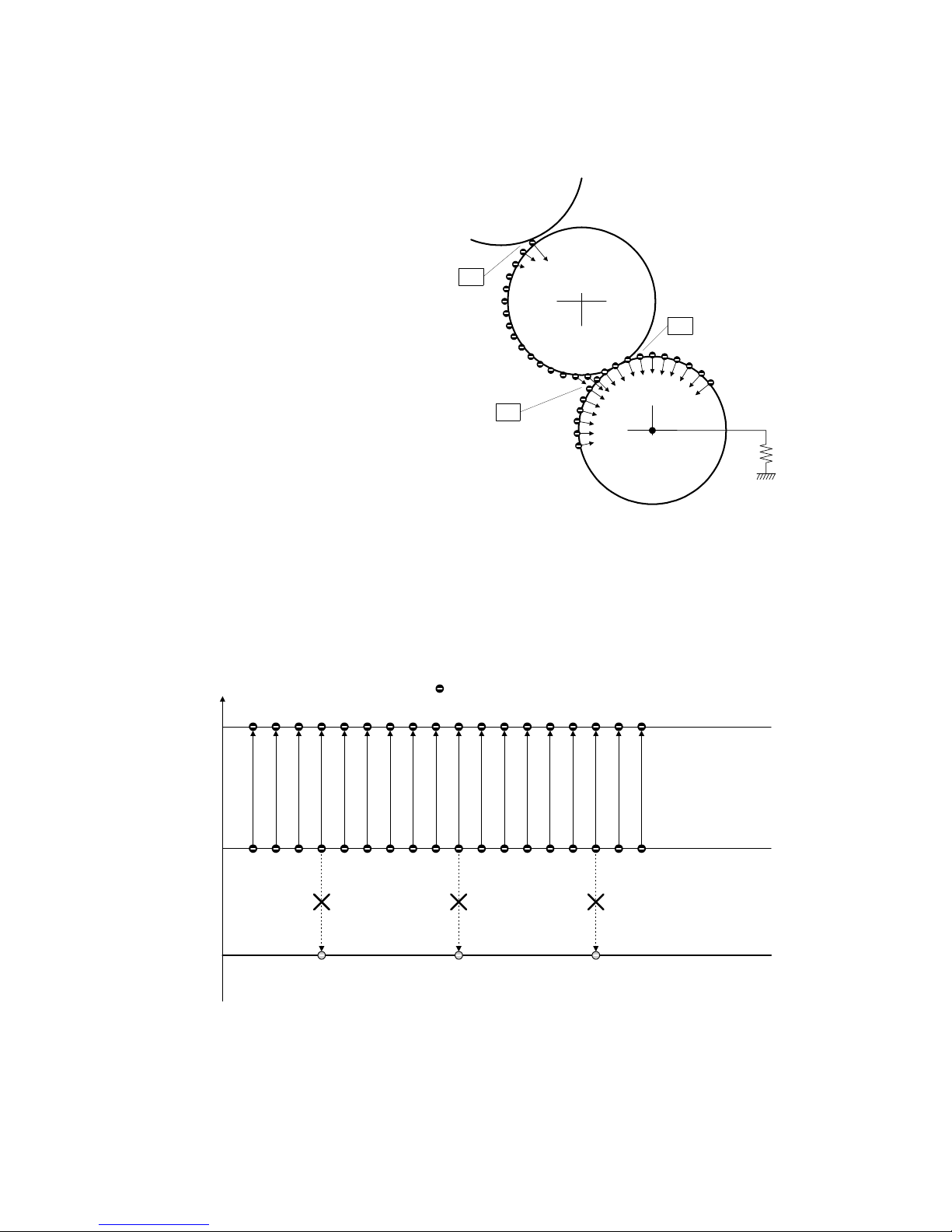
Bias Control (After Each Page)
After each page, the mach ine removes toner from the development
roller and returns it to the de velopment unit. To do this, -4 00 V is
applied to the development roller,
but no bias is applied to the toner
application roller.
Toner does not transfer to the development roller at "A", but remains
on the toner application roller when
it passes between the two rollers.
The remaining toner on th e de velpment roller does not transfer to the
drum at "B", but transfers to the
toner application roller at "C".
In some cases, positively charged
toner may transfer to the drum in
this condition. So, a positive current is applied to the transfer roller
after each page, so that the positively charged toner does not
transfer to the transfer rolle r.
Development Roller
Toner Application Roller
GND
- 750 V
- 400V
Drum Surface Voltage
Toner
H521D656.wmf
- 750 V
- 400V
GND
- 400V
Drum
Development
Roller
Toner
Application
Roller
A
B
C
H521D651.wmf
May 22nd, 1995 DETAILED SECTION DESCRIPTIONS
PRINTING
2-35
Page 64
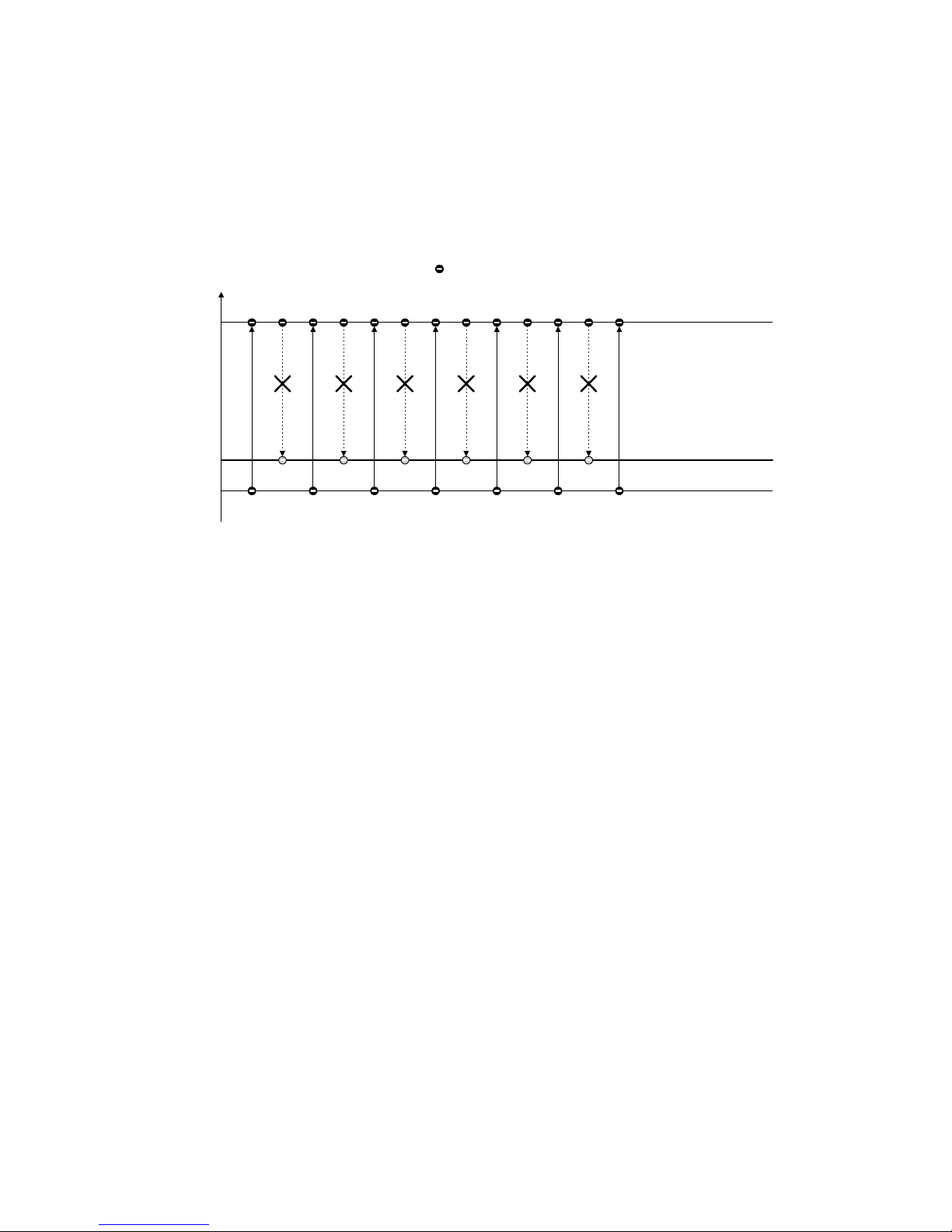
Bias Control (Other)
At the start and the end of any print process (including the cleaning and initial
toner supply modes), -50 ± 50 V is applied to the toner application roller, and
+250 ± 15 V is applied to the development roller. This is to avoid any toner
transfer to the drum.
Note that the voltag e difference between the toner application and development rollers is kept the same as in printin g, at 300 V. This keeps the same
amount of toner on the develo pme nt roller at all times during the print run.
Development Roller
Toner Application Roller
GND
- 50V
+250V
Drum Surface Voltage
Toner
h521d650.wmf
DETAILED SECTION DESCRIPTIONS May 22nd, 1995
PRINTING
2-36
Page 65
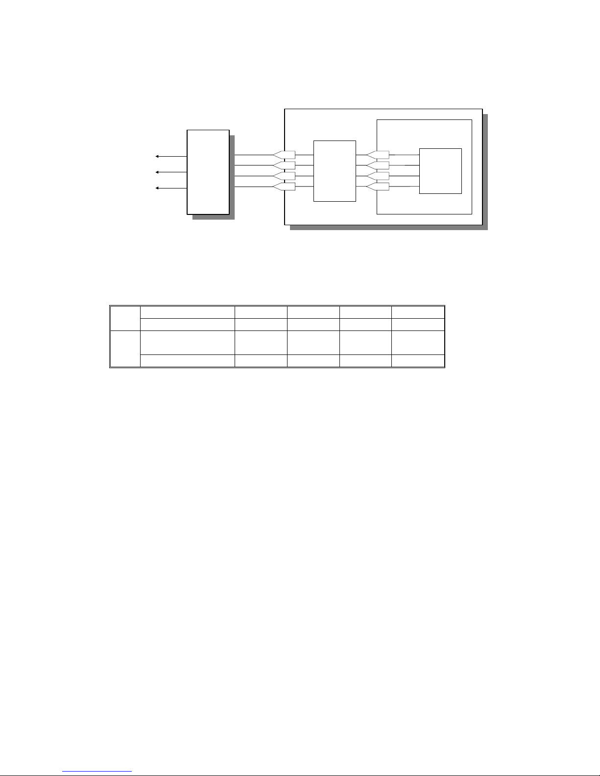
Bias Control Circuit
The cpu controls the volt ag es to the ton er ap plica tion and development rollers using the Bias 0 and Bias 1 signals as shown in the following table.
In
Bias 0 Low High Low High
Bias 1 Low Low High High
Out
T oner Application
Roller
- 700 V - 50 V Off Off
Development Roller -400 V + 250 V -400 V Off
FDU
FCE
CPU
1-44
1-45
1-83
1-87
Power
Pack
Driver
Bias 0
Bias 1
Transfer 0
Transfer 1
Power
Pack
Toner Application
Roller
Development
Roller
Transfer Roller
IC4
21-6
21-7
21-4
21-5
H521D652.wmf
May 22nd, 1995 DETAILED SECTION DESCRIPTIONS
PRINTING
2-37
Page 66

2.2.7. Paper Feed
1. Overview
The standard casset te [A] holds 250 sheets an d th e bypass feed slot [B]
feeds 1 sheet at a time. The bypass feed slot can only be u sed in co py mode.
An optional 100 sheet casse tt e can be fitted into cavity [C].
The registration roller [D] rotates clockwise when the standard casse tt e is
used. It rotates counter-clockwise when the bypass feed slot [B] or the 100
sheet cassette is used.
When a sheet of paper is placed in the bypass feed slot, the bypa ss fee d sen sor [E] is turned on, and th e machine prefeeds the pape r unt il t he re gist ration
sensor [F] is turned on.
[B][C]
[D]
[E]
[F]
[A]
H521D015.wmf
DETAILED SECTION DESCRIPTIONS May 22nd, 1995
PRINTING
2-38
Page 67
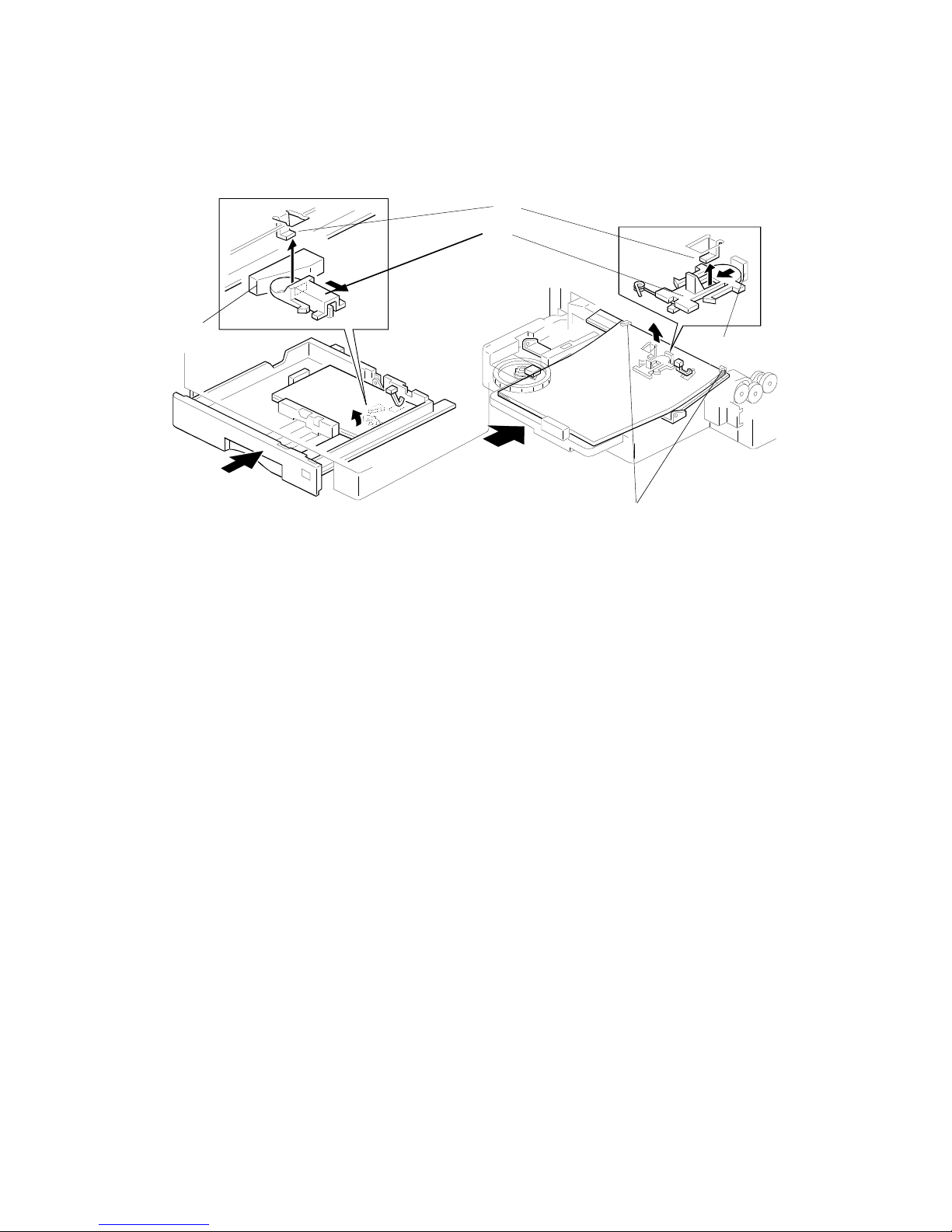
2. Paper Lift Mechanism
Standard and Optional 100 Sheet Cassette
When the cassette is closed af ter paper is loaded, the slide lo ck [A] is pushed
by the projection [B] and comes off the botto m hoo k [ C].
Once the slide lock comes of f, the bottom plate is raised by th e pressure
springs and the top sheet pu she s up ag ain st the corner separators [D]. This
keeps the stack of paper at the correct height.
[D]
[A]
H521D016.wmf
[C]
[B]
[B]
H521D609.wmf
May 22nd, 1995 DETAILED SECTION DESCRIPTIONS
PRINTING
2-39
Page 68
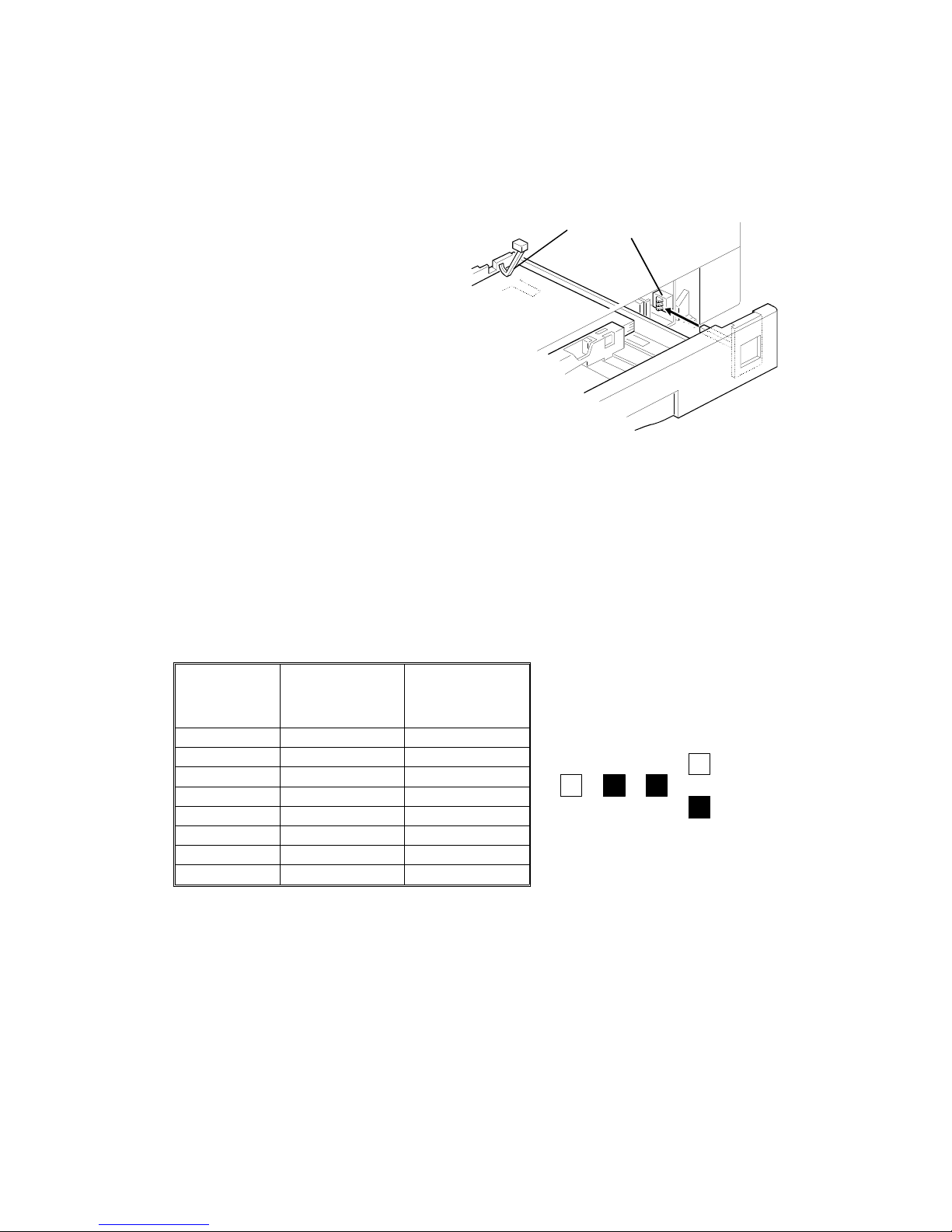
3. Paper Size and Paper End Dete cti on
Standard Cassette/Optional Univers al Cassette
The paper size detector [A] is locat ed
at the front of the cassette.
The machine determines which size
cassette is installed by monitoring
three microswitches.
The machine informs the custo mer
with the Add Pa pe r indicator if the p aper size cannot be detected .
When the cassette runs ou t of pap er,
the paper end sensor actua to r [ B]
drops through a slot in the bot to m
plate.
Selectable cassette paper sizes:
• USA model: Let te r, Half-Letter,
Legal
• Europe/Asia model: A4, A5, B4, B5, F, F4
The following diagram shows the rela tio nsh ip be twe en the activa te d microswitches and the selecte d pape r size.
Microswitch USA Model
Europe/Asia
Model
000 ----- ----001 Legal F/F4
010 ----- B4
011 Letter ----100 ----- B5
101 ----- A4
110 Half-Letter B5 sideways
111 ----- A5
Note: "-----" indicates that the ma chin e de tects that a cassette is not in sta lled.
Microswitches
: 0: High
: 1: Low
Example: Letter size paper
H521D658.wmf
[A]
[B]
H521D018.wmf
DETAILED SECTION DESCRIPTIONS May 22nd, 1995
PRINTING
2-40
Page 69

Bypass Feed Slot
This machine does not detect pape r width wh en the bypa ss fee d slot is use d.
The maximum feed length for bypass feed is 600 mm. The minimum f ee dable
paper size is 100 mm (width) and 148 mm (length).
Optional 100 Sheet Cassette
The paper size detector [A] is locat ed
at the left hand side of the 100 sheet
cassette. The microswitch es work in
the same way as in the standard cassette.
Note:
B4 and B5 sideways paper can no t be
used with the 100 she et ca sset te.
When the 100 sheet cassett e run s o ut
of paper, the paper end senso r a ctuator [B] drops through a slot to detect
paper end.
Paper Size / End Detection
[B]
[A]
H521D611.wm f
FDU
FCE
FCIP
CPU
Paper End Sensor
Standard Cassette
Paper Size Detector
Standard Cassette
Paper Size Detector
100 Sheet Cassette
Paper End Sensor
100 Sheet Cassette
EXIO
20-1
20-2
20-4
25-4
25-6
20-5
25-3
7-1
Paper End
Paper End
H521D659.wmf
May 22nd, 1995 DETAILED SECTION DESCRIPTIONS
PRINTING
2-41
Page 70

4. Pick-up and Separation
Standard and Optional 100 Sheet Cassettes
The pick-up and separatio n mechanism is a corner separator type.
Cross-reference
Group 3 Facsimile Manual: section 4-5-4
The paper feed motor starts to rotate when the printer is read y for prin tin g.
By-pass Feed Slot
There is no pick-up or separation system in th e by-pass feed slot. Only one
sheet can be fed from this slot .
5. Drive Mechanism
Standard Cassette
The paper feed motor [A] drives t he pick-up and fee d mech anism. When the
standard cassette is used, th e pa pe r fee d mot or tu rns clockwise , driving the
paper feed rollers [B] and the registration roller [C], as shown in the diag ram.
The paper feed clutch [D] turns on to allow the paper feed roller to turn only
once for each sheet of paper.
While the registration roller turns coun ter-clockwise , pa per cann ot be fed into
the machine from the opt ion al 10 0 sheet cassette or bypass f ee d slo t. This
means that if a sheet of paper is placed in the bypa ss f eed slot durin g prin ting
from the standard casset te, this sheet will not be fed int o th e machine.
[B]
[A]
[C]
[D]
H521D017.wmf
DETAILED SECTION DESCRIPTIONS May 22nd, 1995
PRINTING
2-42
Page 71

Bypass Feed Slot
When a sheet of paper is placed in the bypass feed slot, the bypa ss fee d sen sor is turned on. The machin e tu rns the paper feed moto r cou nter-clockwise
to prefeed the paper until the registra tion sensor [A] is turned on, or for 1 second, whichever is first.
The paper feed clutch [B] is kept off to prevent any drive from bein g tra nsmit ted to the paper feed rolle rs for the standard cassette when the pap er fe ed
motor turns counter-clockwise.
If a sheet of paper remains in the bypass feed slo t f or longer than the Auto
Reset Time (System Switch 0B), the machine will auto mat ically f ee d it out.
The machine will not print incoming messages while there is a sheet of paper
in the bypass feed slot, so fe ed ing out the page after the A ut o Re set Time allows incoming faxes to be printed even if someone leaves pape r in the
bypass feed slot.
Sheets of paper longer than about 60 cm cannot be fed from the bypass feed
slot, or a paper jam will occur (error code 9-81).
Note that the bypass fe ed slo t can only be used for copying and for printing
from the PC using the optio na l printer interface.
[A]
[B]
H521D019.wmf
May 22nd, 1995 DETAILED SECTION DESCRIPTIONS
PRINTING
2-43
Page 72

Optional 100 Sheet Cassette
When the machine feeds a shee t of pap er fro m t he 100 shee t cassette, the
paper feed motor [A] turns counter-clockwise to drive the paper feed rollers
[B] and the registration roller [C] as shown in the diagram.
The paper feed clutch [D] ensures that the paper fe ed ro ller rot at es only o nce
for each sheet of paper.
Paper Feed Priority
If there is an optional casse tt e installed in the machine, the priority for paper
feed is decided in accordance with the follo wing rules.
• The paper in the bypass feed slot has the first priority (for cop ying and
printing from a PC only).
• If the cassettes contain the same pap er size, the 100 shee t casse tte is
used first.
• If the cassettes contain different sizes, the machin e selects the paper
size as explained in section 2-2-13 , "Pap er Size Sele ction".
[B]
[C]
[A]
[D]
H521D614.wmf
DETAILED SECTION DESCRIPTIONS May 22nd, 1995
PRINTING
2-44
Page 73
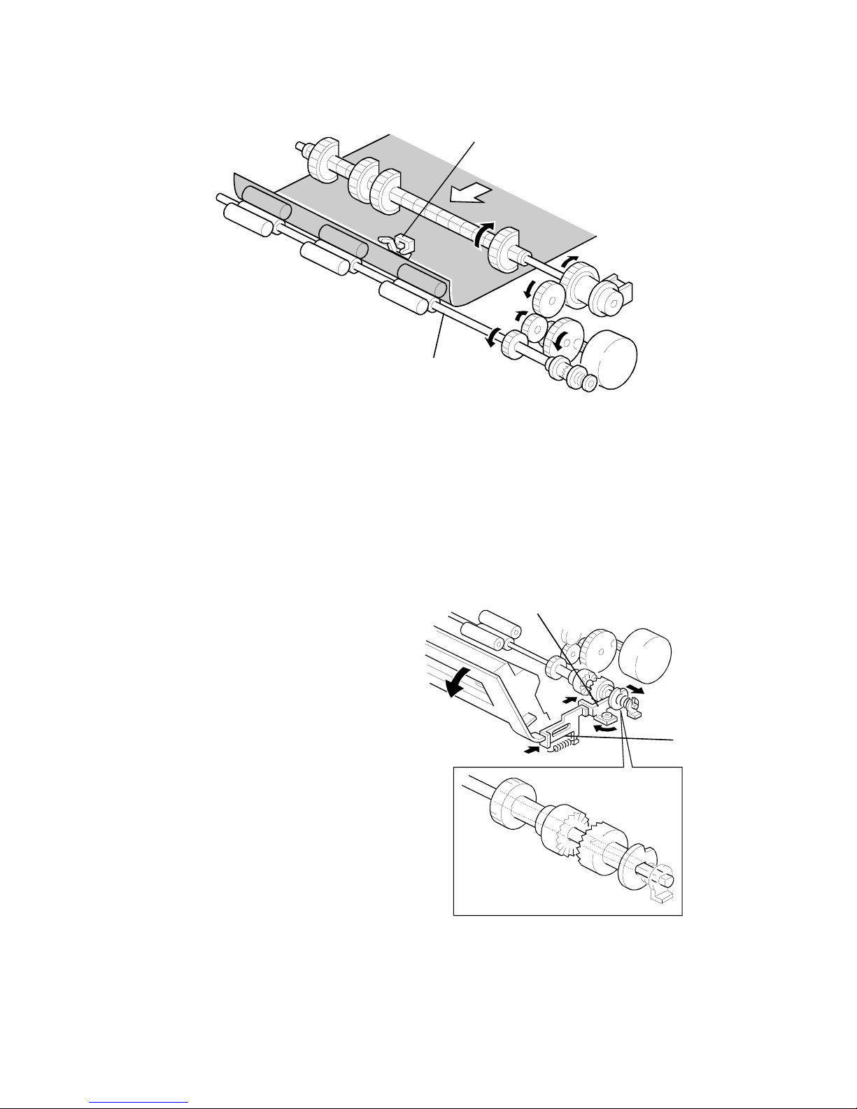
2.2.8. Registration
The registration sensor [A] is p osit ion ed above th e reg istra tion roller [B].
When a cassette (Standard, Universal, or 100 Sheet Cassette) is used, the
machine stops the pape r fee d mot or for a few moments when the regist ration
sensor is turned on.
When the bypass feed slot is used, the ma chin e pre fe ed s the paper un til th e
registration sensor is turned on (or for 1 second, whichever comes first).
Then, the paper feed motor sta rts rot at ing immediately after laser scanin ng
starts.
When the leading edge touches
the pressure rollers, the momentum of the paper corrects any
skew.
When the fusing unit cover is
opened, the door end pushes the
spring lever [C] and the release
lever [D] as shown in the diagram.
This releases drive applied to the
registration roller and allows the
registration roller to rotate freely,
making it easier for a user to remove jammed paper.
This can be done manually by removing the by-pass feed slot
cover and pushing the rele ase
lever [D].
[A]
[B]
H521D017.wmf
[C]
[D]
H521D024.wmf
May 22nd, 1995 DETAILED SECTION DESCRIPTIONS
PRINTING
2-45
Page 74

Jam Detection
Condition Error Code
When the
standard
cassette is used
When the registration sensor is not turned on within
2.0 seconds of the paper feed clutch turning on.
9-07
When the
standard, 100
sheet cassette,
or bypass feed
slot is used
When the paper feed out sensor is not turned on
within 2.6 seconds after the paper feed motor starts to
feed paper for printing (not for prefeed).
9-08
When the registration sensor is not turned off within X
seconds after it turned on.
X seconds = (paper length / 67.546) + 3 seconds
(67.546 mm/ s : paper feed speed)
9-08
When the bypass
feed slot is used
When the registration sensor is not turned on within 2
seconds after the paper feed motor starts rotating for
printing.
(This error is not generated during prefeed, to allow
the users to change their minds after putting paper in
this slot. When the bypass feed sensor is turned on,
the machine prefeeds the paper for up to 1 second
and stops feeding even if the registration sensor is not
turned on. If the registration sensor did not turn on at
prefeed, the machine checks for the above error.)
9-80
When the bypass feed sensor is not turned off within
11.9 seconds after it is turned on.
Using the same formula as above (error code 9-08), it
works out that individual sheets cannot be longer than
about 60 cm.
9-81
When the 100
sheet cassette is
used.
When the registration sensor is not turned on within
2.0 seconds of the paper feed clutch turning on.
9-82
DETAILED SECTION DESCRIPTIONS May 22nd, 1995
PRINTING
2-46
Page 75
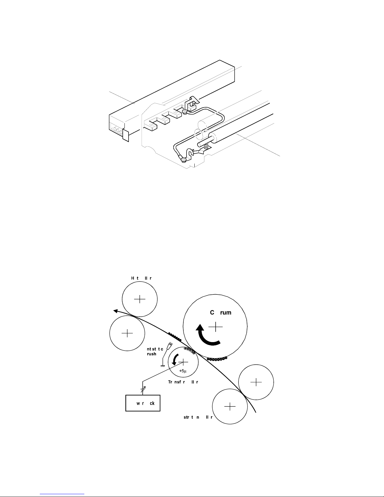
2.2.9. Transfer and Separatio n
Instead of using a transfe r coron a wire, this machine uses a transfer roller,
which touches the dru m surface.
A constant current of +5 ± 0.2 µA is applied to the transfer roller [A] from the
power pack [B]. The positively b iase d tra nsfer roller pulls negatively charg ed
toner off th e dru m. The curvature of the drum and the antistatic brush he lps
the paper to drop away from the drum.
Temperature and humidity have less effect on the supply of ions when the
transfer current is held constant. With a constant voltage, ions may dissipate
in some conditions.
[B]
[A]
H521D620.wmf
H521D653.wmf
May 22nd, 1995 DETAILED SECTION DESCRIPTIONS
PRINTING
2-47
Page 76

Cleaning Mode
If the paper size is smaller than the printed image, or if a paper jam occurs
during printing, toner may be tran sfe rred to the the roller surface. To prevent
this toner from transferrin g to the back side of copies, the transfer roller has
to be cleaned before the next printing run.
While the machine is in the clea nin g mode, the power pack supplie s -1 000V±
50V to the transfer roller, and charges the drum to -750 V. The negatively
charged toner on the transfe r roller is the n tra nsf erred back to the drum.
The machine goes throug h th e cleaning mode in the followin g conditions:
• At power-up (the process starts when th e fu sing temperature reache s
half of the st andby tempera ture)
• When the cover is opened and then closed durin g the printing process.
• After a printer jam has been cleared.
• After the bypass feed slot has been use d (each page): This is done only
if printer switch 00 bit 3 is set to 1.
The cpu controls the tra nsf er roller voltage through th e power pa ck u sing the
Transf er 0 and Transfer 1 signals as shown below (for a circuit diagram, see
Bias Control in section 2-2-6).
In
Transfer 0 Low High Low High
Transfer 1 Low Low High High
Out Transfer Roller
+ 5 µA
- 1000 V Off Off
DETAILED SECTION DESCRIPTIONS May 22nd, 1995
PRINTING
2-48
Page 77
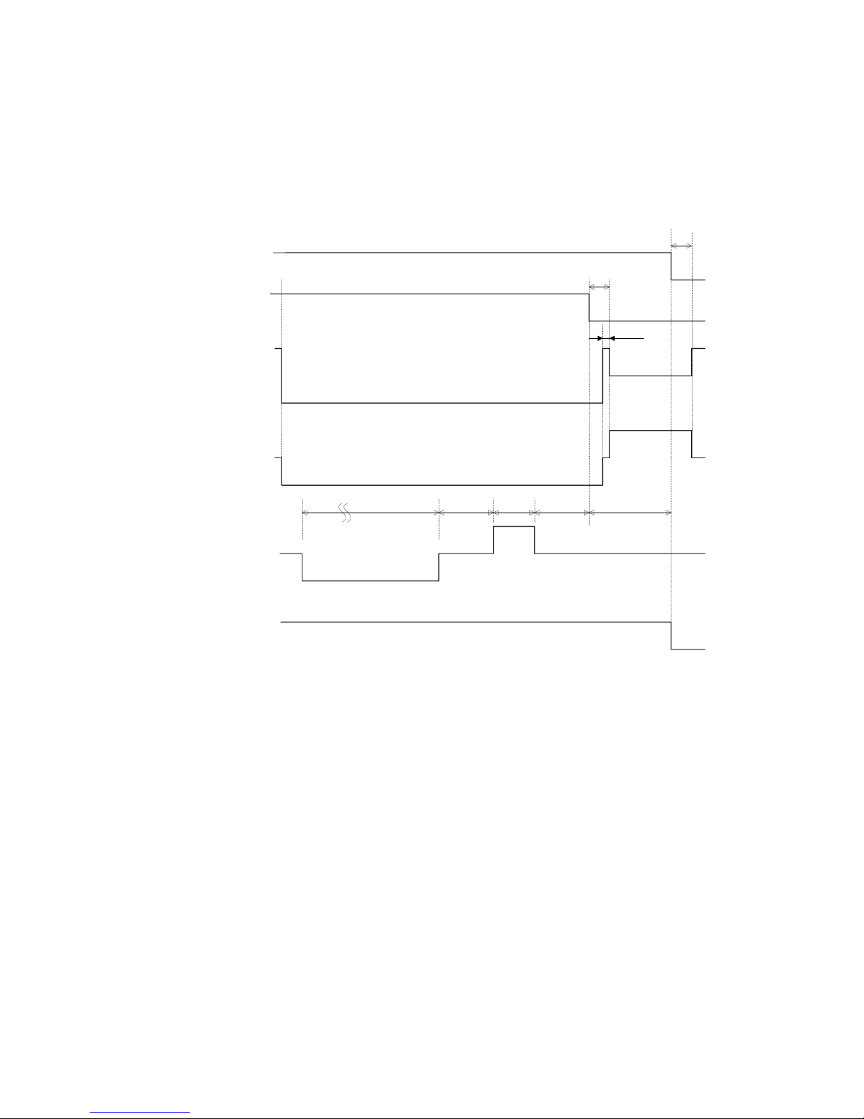
Timing Chart: Cleaning Mode
Before cleaning start s, the main motor, charge corona, and quenching lamp
turn on.
T1. Cleaning bias is applied to the tran sfer roller.
T2. A positive constant curre nt of + 5 ± 0.2 µA is applied to transfer back to
the drum any toner which is positively charged by the transf er rolle r.
Main
Motor
Charge
Toner
Application
Roller
Development
Roller
Transfer
Roller
Quenching
Lamp
0.3
1 1.40.670.75
5 (Bypass feed: 6.5)
0.02
GND
ON
ON
ON
OFF
OFF
OFF
-50V
-700V
+250V
GND
-400V
+5
µ
A
-1000V
0.270
T1
T2
H521D663.wmf
May 22nd, 1995 DETAILED SECTION DESCRIPTIONS
PRINTING
2-49
Page 78

2.2.10. Cleaning
The cleaning unit and the used toner tank a re contained in the CTM.
The cleaning blade [A] removes any toner remaining on th e drum after the im-
age is transferred to the paper. A magnetic roller [B] then brings the toner into
the used toner tank [D]. The mylar b lad e [C] scrape s the to ne r off the magnetic roller into the used toner tank [D].
When the CTM is removed from the machine, the cleaning roller cover [E] is
closed by a spring. This prevents remo ved ton er fro m f allin g out of th e unit.
There is no used toner overflow det ect ion me cha nism be cau se th e use d
toner tank is large enough for the lifetime of the CTM.
[A]
[B]
[E]
[D]
[C]
H521D621.wmf
DETAILED SECTION DESCRIPTIONS May 22nd, 1995
PRINTING
2-50
Page 79

2.2.11. Fusing
Fusing Lamp Control
When the main switch is turned on , th e machine turns on the fusing la mp
and raises the fusing temp erature to 80 °C in about 6 s. For printing, the machine raises the fusing temp erature to 185 °C.
When the Power Saver Key is pressed or the power saver timer expires, the
machine goes into a power save r mode . In Level 2 Power Saver Mode, the
fusing lamp is turned off. For Power Saver Mode Level 1, the user can select
whether to keep the fusing lamp off, or at 80 °C or at 145 °C.
Cross Reference:
Power Saver Modes: Section 2-3
If the printing opera tion continues for more than 3 minu tes, the machine
keeps the fusing tempe rature at 175°C.
Points to Note:
• Standby temperature: 145 ° C
• Printing start temperature: 160 °C
• Printing temperature: 185 °C (monitored by a comparator)
• Thermistor maximum: 250 °C
• Thermostat maximum: 150 °C (the temperature of the hot roller would
be about 400 °C)
• Thermofuse maximum: 169 °C (the temperature of the hot roller would
be about 400 °C) - The thermofuse is not used in USA models.
AAA
AAA
AAA
AAA
AAA
AAAA
AAAA
AAAA
AAAA
AAAA
AAAA
AAAA
AAAA
AAAA
AAAA
AAAA
AAAA
AAAA
AAAA
AAAA
AAAA
AAAA
AAAA
AAA
AAA
A
AAA
A
AAA
A
AAA
A
AAAA
AAA
AAA
AAA
AAA
AAA
A
A
A
A
A
A
A
A
A
AA
AAAA
AAAA
AAAA
AAAA
AAAA
A
A
A
A
A
A
A
A
A
AA
AAAA
AAAA
AAAA
AAAA
AAAA
AAAA
AAAA
AAAA
AAAA
AAAA
AAAA
AAAA
AAAA
AAAA
AAAA
AAAA
AAAA
AAAA
AAAA
AAAA
AAAA
AAAA
AAAA
AAAA
AAAA
AAAA
AAAA
AAAA
AAAA
AAAA
AAAA
AAAA
AAAA
AAAA
AAAA
AAAA
AAAA
AAAA
AAAA
AAAA
AAAA
AAAA
AAAA
AAAA
AAAA
AAAA
AAAA
AAAA
AAAA
AAAA
AAAA
AAAA
AAAA
A
A
A
A
A
A
A
A
A
AA
AAA
AAA
AAA
AAA
AAA
A
A
A
A
A
A
A
A
A
AA
AAAA
AAAA
AAAA
AAAA
AAAA
A
A
A
A
A
A
A
A
A
AA
AAAA
AAAA
AAAA
AAAA
AAAA
A
A
A
A
A
A
A
A
A
AA
AAAA
AAAA
AAAA
AAAA
AAAA
AA
AA
AA
AA
AA
AAA
AAA
AAA
AAA
AAA
AA
AA
A
AA
A
AA
A
AA
A
AAA
80°C
160°C = Print ready
185°C
175°C
Room temp.
Ring
Detection
or
Copy Start
Fusing
ON
OFF
Print Start
3 minutes
5 minutes (= Power saver timer)
145°C, 80°C
or
Room Temp
Power ON
Temperature
145°C
H521D654.wmf
May 22nd, 1995 DETAILED SECTION DESCRIPTIONS
PRINTING
2-51
Page 80

Fusing Control
During normal operation, the cpu controls the fusing lamp based on input
from the thermistor using th e ab ove circuit.
When the machine switches on, or when it comes back from the Level 2
Power Saver Mode, it checks whether the thermistor circuit is intact by temporarily closing the initial detect switch circuit on the FDU. If the thermisto r is
connected properly, the machine begins norma l op era tion. If it is not, an Aut o
Service Call (error code 9-22, sub-co de 09) is genera ted.
As a backup safety measure, when the temperature of the hot roller reaches
about 400 °C, the thermostat and/or the thermofuse open (the thermofuse is
not installed in USA models).
The machine turns on the cooling fan when the fusing temperature reaches
120 °C. It is turned off when the fusing temperature drops below 120 °C.
FDU
FCE
CPU
25-1
25-2
12-1 12-2
Comparator
+5V
+5V
Intial Detect ON/
OFF
Heat
Enable
Heat On
Thermistor Temp
Thermistor Max
Thermistor
1-51
1-69
1-17
1-52
1-78
PSU
Thermofuse Thermostat
Fusing Lamp
*
H521D662.wmf
* The thermofuse is not
used in USA models.
DETAILED SECTION DESCRIPTIONS May 22nd, 1995
PRINTING
2-52
Page 81

Fusing Unit Drive
The main motor [A] drives th e fu sing unit through a gear tra in. The paper
feed-out sensor [B] detects when the paper is fed out of the unit.
Jam Detection - Paper Feed Out
The machine detects a pap er jam whe n the paper feed out sensor is not
turned off within X secon ds or more aft er it is turned on (error Code 9-09).
X seconds = (paper length / 67.546) + 3 second s
(67.546 mm/s is the paper feed speed)
These conditions are the same fo r the stan dard (universal) cassette, bypass
feed, and optional 100 sheet cassette.
[A]
[B]
H521D622.wmf
May 22nd, 1995 DETAILED SECTION DESCRIPTIONS
PRINTING
2-53
Page 82

Service Call Conditions
Conditions
Error Code
(9-22)
At power on If there is any problem with the thermistor.
(This detection is also done when the machine comes
back to the normal mode from the Power Saver Mode
Level 2.)
Sub-code 09
Standby mode
If the fusing temperature stays below 80 °C for more
than 18 seconds when power saver standby
temperature (80 °C) is selected in Power Saver Mode
Level 1.
Or, if the fusing temperature stays below 145 °C for
more than 25 seconds when the standby temperature
(145 °C) is selected in Power Saver Mode Level 1.
Sub-code 05
If the fusing temperature takes more than 40 seconds to
reach 160 °C from the standby temperature.
Sub-code 02
During
printing
If the fusing temperature stays above 185 °C for more
than 40 seconds.
Sub-code 01
If the fusing temperature comes below 140 °C during
printing.
Sub-code 07
After printing If the fusing temperature takes more than 20 minutes to
go down to below 100 °C when the machine goes into
the Power Saver Mode Level 1. (When fusing lamp OFF
is selected for Power Saver Mode Level 1.)
Sub-code 03
Either: If the fusing temperature takes more than 20
minutes to go down to below 100 °C when the machine
goes into the Power Saver Mode Level 1 (when the
power saver standby temperature of 80 °C is selected
for Power Saver Mode Level 1.)
Or: If the fusing temperature takes more than 5 minutes
to go down to the standby temperature (145 °C) when
the standby temperature is selected for Power Saver
Mode Level 1.
Sub-code 04
At any time
If the fusing temperature reaches 250°C.
Sub-code 08
DETAILED SECTION DESCRIPTIONS May 22nd, 1995
PRINTING
2-54
Page 83

2.2.12. Page Separation and Data Reducti on
Incoming pages that are only slightly longer than the copy pape r may be reduced in the sub-scan direction. Whether or not this happens depends on the
settings of printer bit switch es 04 and 05.
Reduction Enabled
If bit 0 of printer switch 03 is at 1 (Enabled), the data will be reduced in the
page memory to fit on the copy paper. However, da ta will only be red uce d if
the length of the incoming page is between 5 mm shorter and a certain maximum length. This maximum incoming page length that can be reduced
depends on the copy paper size and on the reduction ratio stored in printer
switches 04 and 05.
Each paper size can be programmed with a separate reduction ratio. In each
of the two bit switches, there is one bit for each possib le p ap er size . Th e co mbination of the bit settings de termines the ratio for that paper size.
Bit No.
Switch
No.
Bit 7 Bit 6 Bit 5 Bit 4 Bit 3 Bit 2 Bit 1 Bit 0
Not
used
B4
Legal
FA4
B5
Letter
B5
sidewaysA5sideways
HLT
Sw 04 0: 3/2 1: 4/3 0: 8/7 1: 12/11
0: 0: 1: 1:
Sw 05
The following table shows the maximum incoming page length that can be reduced for each copy paper size. All leng th are in millimeters. The factory
setting of the reduction ratio is 4/3.
USA Model
Copy Paper
Type
Copy Paper
Length
Maximum reducible incoming page lengths
Ratio = 4/3 Ratio = 8/7 Ratio = 12/11
Half-Letter 139.5 179.0 153.2 146.5
Letter 279.2 365.2 313.0 298.7
Legal 355.6 467.0 400.3 382.1
Europe/Asia Model
Copy Paper
Type
Copy Paper
Length
Maximum reducible incoming page lengths
Ratio = 4/3 Ratio = 8/7 Ratio = 12/11
A5 147.8 190.1 162.9 155.3
B5 181.8 235.8 201.8 192.5
A4 296.9 388.8 333.2 318.2
F/F4 330.1 433.2 371.2 354.3
B4 363.9 478.2 409.9 391.1
May 22nd, 1995 DETAILED SECTION DESCRIPTIONS
PRINTING
2-55
Page 84

Incoming pages that are longer than the maximum length will not be reduced,
but will be printed on two pages and treated in accord an ce with the setting of
bit 1 of bit printer switch 00. If this bit is 1, the bot tom few line s of th e page
will continue from where the first page lef t off.
Reduction Disabled
If bit 0 of printer switch 03 is at 0 (Disabled), the data will not be reduced.
However, if the incoming page is up to x mm longer than the copy paper, the
excess portion will not printed. The value of x can be from 0 to 15 mm. It is
determined by the setting of bits 4 to 7 of printer switch 03.
Hex value Value of X
00
01
and so on until
F15
Messages more than x mm longer than the cop y pap er will be prin ted out on
two pages in accordance with the sett ing of bit 1 of printe r switch 00 as explained earlier.
DETAILED SECTION DESCRIPTIONS May 22nd, 1995
PRINTING
2-56
Page 85

2.2.13. Paper Size Selection
If there is an optional casse tt e installed in the machine, the paper size to use
is decided in accordance with the following rules.
• If both cassettes contain the sa me pape r size , th e 10 0 sheet cassette
will be used.
• If the received page has to be split up and printed on two pages, both
pages will be the same size.
• If the cassettes contain different sizes, the paper size chosen for print-
ing the received fax message is select ed in accord ance with the following table of priorities. The table assume s tha t re du ctio n is ena ble d a nd
that the reduction rat io is 4 /3 .
Received Fax
Message Size
Selected Paper Size
HLT A5 LT A4 F,F4 LG B5 B4
Half-Letter 1
2
sideways
3456
7
sideways
8
A5 sideways
1
sideways
2345
6
sideways
7
Letter 7(SR)
6(SR)
sideways
1234
8(SR)
sideways
5
A4 7(SR)
6(SR)
sideways
5(R) 1 2 3
8(SR)
sideways
4
F, F4 7(SR)
6(SR)
sideways
5(R) 4(R) 1 2
8(SR)
sideways
3
Legal 7(SR)
6(SR)
sideways
5(R) 4(R) 3(R) 1 8(SR) 2
B5 sideways
1
sideways
2
B4
2(SR)
sideways
1
•
The paper size priority is graded from 1 to 5.
• S: The data has to be separated and printed on more than on page.
• R: The data is reduced to fit on the prin ter paper.
• Some of the reports can be printed on A5 paper without p age se pa ra-
tion. However, if only A5 paper is in the cassettes, repo rts t hat n ee d
larger paper sizes will require page separation.
May 22nd, 1995 DETAILED SECTION DESCRIPTIONS
PRINTING
2-57
Page 86

2.3. SYSTEM FEATURES
2.3.1. Power Saver Modes
The machine has three le vels of powe r sa ver mod e as shown below.
Normal Level 0 Level 1 Level 2
Main CPU ON ON ON OFF
Power Saver CPU OFF OFF OFF ON
Power Saver LED OFF ON ON ON
LCD/LED ON OFF OFF OFF
+5V Power Supply ON ON ON OFF
+24VM Power Supply ON ON ON OFF
Fusing Lamp
ON
Standby temp.
or OFF
Standby temp.
or OFF
OFF
+24VM Power Supply ON ON ON OFF
In power saver mode levels 0 and 1, the main CPU mon ito rs and cont rols the
system. The fusing lamp is eith er turned off or kep t a t t he standby temperature, depending on the settin g of Use r Para meter Switch 05, bits 6 and 7.
In level 2, the main CPU and dc powe r su pp lies are shut down. The power
saver CPU monitors the power saver key, incoming calls, and the document
sensor. When the power saver CPU detects activity at one of the se, it activates the +5V supply with the WAKEUP signal to start up the main CP U.
The following section s expla in ho w the ma chin e controls these three mode s.
Note that power saver mode does not operate if an optional printer inte rfa ce
or RS232C kit is installed.
FDU
FCE
AAAA
AAAA
AAAA
AAAA
AAAA
AAAA
AAAA
AAAA
AAAA
AAAA
AAAA
AAAA
AAAA
AAAA
AAAA
AAAA
AAAA
AAAA
AAAA
AAAA
AAAA
AAAA
AAAA
AAAA
AAAA
AAAA
AAAA
AAAA
AAAA
AAAA
AAAA
AAAA
AAAA
AAAA
AAAA
AAAA
AAAA
AAAA
AAAA
AAAA
AAAA
AAAA
AAAA
AAAA
AAAA
AAAA
AAAA
AAAA
AAAA
AAAA
AAAA
AAAA
AAAA
AAAA
AAAA
AAAA
AAAA
AAAA
AAAA
AAAA
AAAA
AAAA
AAAA
AAAA
AAAA
AAAA
AAAA
AAAA
AAAA
AAAA
AAAA
AAAA
AAAA
AAAA
AAAA
AA
A
AA
A
AA
A
AA
A
AA
A
AA
A
AA
A
AA
A
AA
A
AA
A
AA
A
AA
A
AA
A
AA
A
AAA
FCIP
Main
CPU
PSU
Interlock Switch
+24VD
+24VM
Q6 and Q13
DC/DC
Converter
(+24/+5V)
Q2, Q3 and Q14
+5V+5VE +5VV
5
+24VMON
5
5 5
24
RESET
COMMAND
STATUS
NCU
Ring
Detection
Circuit
Current
Sensor
(Europe/
Asia)
EXRING
+5VEE
HOOK0/HOOK1
+5VE
+5V
+24VM
+5VE
Contact
Image
Sensor
Motors
and
Clutches
Operation Panel
LED ON/OFF
Doc. Sensor
Power Saver Sw.
Power Saver
Key
Power Saver
LED
Document
Sensor
WAKEUP
Power Saver
CPU
IC5
+5VV
+24VM
h521d625.wmf
DETAILED SECTION DESCRIPTIONS May 22nd, 1995
SYSTEM FEATURES
2-58
Page 87

1. Going into a Power Saver Mode
The flow chart on the next pa ge explains how the machine goes into a po wer
saver mode, dependin g on parameter settings and ot he r machine conditions.
Entering Power Saver Mode from Standby
- Power Saver Timer -
When the power saver timer expires since th e last time a condition #1
operation was detect ed (see the flow chart), the mach ine aut omatically goes
into a Power Saver Mode. See the point marked 1 on the flow chart.
Cross Reference
Power saver timer initial setting: System Switch 0B, bits 2 and 3
(1 minute, 3 minutes, 5 minutes, or Unlimited: Timer disabled)
- Power Saver Key -
When this key is pressed, the machine che cks if there are any background
operations in progress (th ese are the condition #2 operations on the flow
chart). If there are none, the machin e will a ut oma tica lly g o int o a Power
Saver Mode. See point 2 on the flow chart.
Which Power Saver Mode is Selecte d ?
If User Switch 05, bits 6 and 7 are set to main tain the fusing lamp at a certain
temperature during Powe r S ave r Mode , th e machine enters Power Saver
Mode Level 1. See point 3 on the flow chart.
If User Switch 05, bits 6 and 7 are set to kee p the fusing lamp of f du ring
Power Saver Mode, the machine checks for events liste d on the flow cha rt as
condition #3 events (see poin t 4 on the flow cha rt). If none exist, the machine
goes to Power Saver Level 2. If one or more does exist, the ma chin e en te rs
Power Saver Level 1 until the cond itio ns are all cleared. then it goes to Power
Saver Level 2.
See the next flow chart for more deta ils o n how the machin e changes from
Level 1 to Level 2.
Cross Reference
Fusing lamp control during Power Saver Mode: User Switch 05, bits 6 and 7
(On at printing temperature, On at standby temperature, or Off)
Note
The "optional equipment" in condition #3 is either a Printer Interface or a RS232C
Interface.
May 22nd, 1995 DETAILED SECTION DESCRIPTIONS
SYSTEM FEATURES
2-59
Page 88
Timer=0
Standby Mode
Power Saver Mode
Level 1
Power Saver Mode
Level 2
LCD=OFF
LED=OFF
Fusing=OFF
Main CPU=OFF
Power Saver CPU=ON
User SW 05
Bit 6,7
Condition
#1
Timer=T
Condition
#3
No
Yes
No
Other
Fusing Lamp=OFF
No
Power Saver
Key ?
NoOR
Condition
#2
OR
Yes
Condition
#4
Yes
No
System SW 0B
Bit 2,3
Other
Mechanical Errors (Jam, Toner
end, Paper end, etc.)
Original detected
Communication Error
NCU Off Hook
Optional Equipment Installed
Memory 100%
Tx File/Polling Rx File Exists
Condition #3 all
cleared.
Machine is in operation.
Machine is in a service call
condition.
Machine is in a service
mode operation.
T=1, 3, or 5 minutes
No
Yes
Unlimited
Power Saver
Key ?
Yes
No
Key pressed
Original detected
Handset off-hook
If key was pressed
in the above
condition.
Power Saver Mode
Level 1
LCD=OFF
LED=OFF
Fusing=User Sw 05 Setting
Main CPU=ON
Power Saver CPU=OFF
Yes
Yes
2
1
3
4
1
1
h521d626.wmf
DETAILED SECTION DESCRIPTIONS May 22nd, 1995
SYSTEM FEATURES
2-60
Page 89

2. Going into Level 2 Mode from Level 1 Mode
The flow chart on the next pa ge sh ows in more det ail ho w the machine goes
from Power Saver Mode Level 1 to Level 2.
The machine will not go into Leve l 2 powe r saver mode if one of the following
conditions exists.
• Either a tx/rx/polling file is stored in the memory.
• SAF memory not empty
• Mechanical error(s)
• NCU off-hook
• Optional equipment installed (a printe r in te rface and/or a RS232C inter-
face)
If there is a tx file in the memory
The machine stays in Power Saver Mode Le vel 1 until it is t ime to send the
message. The machine the n enters Level 0 while the messag e is se nt. See
point 1 on the flow chart.
When the Power Saver timer expires
When the power saver timer expires aft er th e machine entered Level 1 for the
first time (or, if a tx file was present, after the message was transmitted), the
machine will enter Level 2 if both of th e following are met:
• User Switch 05, bits 6 and 7 specify Fusing Lamp Of f
• No condition #1 restrictions exist.
See point 2 on the flow chart.
May 22nd, 1995 DETAILED SECTION DESCRIPTIONS
SYSTEM FEATURES
2-61
Page 90
Tx time ?
Yes
Yes
Power Saver Mode
Level 0
LCD=OFF
LED=OFF
Fusing=User SW 05 Setting
Main CPU=ON
Power Saver CPU=OFF
Message Transmission
No
Power Saver Mode
Level 1
LCD=OFF
LED=OFF
Fusing=User SW 05 Setting
Main CPU=ON
Power Saver CPU=OFF
Tx file in
memory ?
No
Power Saver Mode
Level 2
LCD=OFF
LED=OFF
Fusing=OFF
Main CPU=OFF
Power Saver CPU=ON
Timer=0
Timer=T
System SW 0B Bit 2,3
T=1, 3, or 5 minutes
User SW 05
Bit 6,7
Fusing Lamp=OFF
Yes
No
Condition #1
No
ORNo
Yes
Mechanical Errors
Original detected
Communication Error
NCU Off-Hook
Optional Equipment Installed
Memory 100%
Tx File/Polling Rx File Exists
1
2
h521d627.wmf
DETAILED SECTION DESCRIPTIONS May 22nd, 1995
SYSTEM FEATURES
2-62
Page 91

3. Receiving a Fax Message in Power Saver Mode
The flow chart on the next pa ge explains how the machine receives a fa x
message while it is in a power saver mode.
Ring Detection
While the machine is in a power saver mode, the power saver CPU monitors
ringing signals from the line. When the powe r saver CPU has det ected two
ringing signals, it activate s the +5V supply to the main CPU and passes the
ring detection process to the main CPU.
After the main CPU has detected a ringing signal, th e machine goes to Power
Saver Mode Level 0 and receives the fax into memory. Level 0 mode looks
the same as the previous mode for users, but all the system compone nt s ar e
active in the background for receiving a fax message.
See point 1 on the flow chart.
Printing
If either of the following condit ion s is not met (cond itio n #1 on the flow ch art ),
the machine will print out the fax message then ret urn to Power Saver Mode
in the manner described in the previous two flow charts in this section.
• Power Saver mode is activated during the Nigh t Timer period
• The machine is currently in the Night Timer period.
If both conditions are met, the ma chin e ret urns to Power Saver Mode as described in the previous two flow charts in this section. It will print the fax
message after th e Nig ht Timer expires.
See point 2 on the flow chart.
Cross Reference
Night Timer On/Off: User Function 62
Programming the Night Timer period: User Function 72
May 22nd, 1995 DETAILED SECTION DESCRIPTIONS
SYSTEM FEATURES
2-63
Page 92

Power Saver Mode
Level 2
LCD=OFF
LED=OFF
Fusing=OFF
Main CPU=OFF
Power Saver CPU=ON
Ring Detection
Condition #1
Yes
Power Saver Mode
Level 0
LCD=OFF
LED=OFF
Fusing=OFF
Main CPU=ON
Power Saver CPU=OFF
Memory Reception
Power Saving
Mode Program
No
No
Power Saver Mode
Level 1
LCD=OFF
LED=OFF
Fusing=User SW 05 Setting
Main CPU=ON
Power Saver CPU=OFF
Power Saver Mode is enabled by
User Function 62, and the machine
is in a Night Timer period.
Yes
Fusing Heat-up
Message Printout
1
2
h521d628.wmf
DETAILED SECTION DESCRIPTIONS May 22nd, 1995
SYSTEM FEATURES
2-64
Page 93

4. Sending a Fax Message or Copying in Power Saver Mode
The flow chart on the next pa ge explains how the machine wakes up fro m
power saver mode upon a manual op era tion, and how it comes back to a
power saver mode.
Manual Wakeup Conditions
While the machine is in a power saver mode, either the power saver CPU
(Level 2) or the main CPU (Level 1) monitors signals from the following (con dition #1 on the flow chart ).
• Power saver key
• Document sensor
• Off-hook detecto r on th e NCU
When a signal from one of these ha s bee n detected, the CPU wakes up all
the components and the machine enters normal operat ing mode, even during
the Night Timer period.
After operations ha ve been finished, the machine goes back to a power saver
mode as explained in the pre vious sections.
May 22nd, 1995 DETAILED SECTION DESCRIPTIONS
SYSTEM FEATURES
2-65
Page 94

Condition #1
Yes
No
Power Saver Mode
Level 2
LCD=OFF
LED=OFF
Fusing=OFF
Main CPU=OFF
Power Saver CPU=ON
Normal Mode
LCD=ON
LED=ON
Fusing=ON
Main CPU=ON
Power Saver CPU=OFF
Message Printout
Phone communication
Fax transmission
Making copies
etc.
Power Saving
Mode Program
Standby Mode
Yes
Yes
Message received
in memory ?
Operation
Finished ?
No
No
Power Saver key pressed
Document set in ADF
NCU off-hook
Power Saver Mode
Level 1
LCD=OFF
LED=OFF
Fusing=User SW 05 Setting
Main CPU=ON
Power Saver CPU=OFF
h521d629.wmf
DETAILED SECTION DESCRIPTIONS May 22nd, 1995
SYSTEM FEATURES
2-66
Page 95

2.3.2. Automatic Service Calls
1. Service Call Conditions
The machine makes an automatic service call wh en one of th e following conditions occurs.
Service Call Conditions Error Code
Sub-code
(8003B5H)
Charge corona unit failure 9-17 11 or 12
Laser diode failure 9-20 21
Fusing lamp failure 9-22 01 to 09
Polygonal mirror motor failure 9-23 31 or 32
Main motor failure 9-24 41 or 42
Excessive jams in the ADF/scanner None None
Excessive jams in the printer None None
The PM counter has reached the threshold (60,000
prints)
None None
The PM interval has expired None None
Cross reference
Service station number: Service Function 13
Troubleshooting: Chapter 6
May 22nd, 1995 DETAILED SECTION DESCRIPTIONS
SYSTEM FEATURES
2-67
Page 96

2. Excessive Jam Alarm s
The excessive jam alarm automatica lly n otifies the service station when the
machine’s scanner or print er fre qu ently has ja m prob lems.
Each type of jam has three counters allo cated to it (JAM, NO-JAM1, NOJAM2). Each of these coun ters has a threshold value (CA LL , DEC, and CLR
respectively; these can be adju sted.) The machine use s th ese counters to
monitor jams as follows.
Each time a jam occurs: The JAM counter is increased by 1, and NO-JAM1
and NO-JAM2 are both set to zero. When JAM reach es CALL (6 by default ),
the machine sends an Aut o S ervice Report with a System Parame ter List.
If a sheet of paper is fed without a jam occuri ng: NO-JAM1 and NO-JAM2
are both incremented by 1. When NO-JAM1 reaches DEC (16 by default ),
NO-JAM1 is set to zero, and JAM is decremente d by 1. When NO-JAM2
reaches CLR (48 by default), NO-JAM2 and JAM a re both reset to zero.
The CALL, DEC, and CLR thresh olds can be adjusted for each type of jam
by rewriting RAM data. The addresse s of th ese thre sholds are given on the
next page.
6
1
2
3
4
5
0
3224168 64564840 72
16
8
0
3224168 64564840 72
4
12
48
16
32
0
3224168 64564840 72
JAM
NO-JAM1
NO-JAM2
CALL Threshold (=6)
DEC Threshold (=16)
CLR Threshold (=48)
OR
16 pages fed without jam 16 pages fed without jam 16 pages fed without jam
48 pages fed without jam
Decrement
Decrement
Reset to
zero
H521D635.WMF
DETAILED SECTION DESCRIPTIONS May 22nd, 1995
SYSTEM FEATURES
2-68
Page 97

Parameters
Address (H) Initial
Settings
Sys. Para.
List
ADF Printer
DEC (1 - 255; 0 = Disabled) 8001DD 8001E1 10 (H) X
CALL (3 - 15; 0 = Disabled) 8001DE 8001E2 06 (H) Y
CLR (Low)
(High)
8001DF 8001E3 30 (H)
—
8001E0 8001E4 00 (H)
Counters
Address (H)
Sys. Para. List
ADF Printer
JAM: Jam counter used to place a
service call
8001D6 8001DA Z
NO-JAM1: Counter used for JAM
counter decrement
8001D5 8001D9 —
NO-JAM2: Counter used for clearing the JAM counter
8001D7 (Low) 8001DB (Low)
—
8001D8 (High) 8001DC (High)
The system parameter list gives the curren t DEC an d CAL L thresholds and
JAM counter value as X, Y, and Z respectively.
The Call Service indicator does not ligh t fo r an exce ssive jam ala rm, an d th e
machine can be operated normally af te r the aut oma tic service call h as been
made. Also, the cou nt ers related to the ja m location are reset to zero automatically after the call. Then the alarm is disab led unt il either bit 3 or bit 4 of
address 80033d is reset to zero.
3. Periodic Service Call
The periodic service call notifies the con dition of the machine to the service
station. The call is made periodically at a time interval programmed in the following RAM addresses.
Parameters Address (H)
Call interval: 01 through 15 month(s) (BCD)
00: Periodic Service Call Disabled
800256
Date and time of the next call
Year: last two digits of the year (BCD) 800257
Month: 01 through 12 (BCD) 800258
Day: 01 through 31 (BCD) 800259
Hour: 00 through 23 (BCD) 80025A
To change these settings after pro gra mming, change the call interval. The n
the machine automatically cha ng es th e rema ining parameters by referring to
the interval and the current date and time.
The Call Service indicator does not light for a periodic service call, so th at the
machine can be operated normally af te r it has sen t the service call.
May 22nd, 1995 DETAILED SECTION DESCRIPTIONS
SYSTEM FEATURES
2-69
Page 98

4. PM Call
If PM call is enabled, the machine will make an automatic service call when
the PM counter reaches the PM threshold.
Program the PM call interval at th e fo llowin g RAM ad dre s ses.
(Default setting: 60,000 sheets)
Address (H) Bits 7 - 4 Bits 3 - 0
800194 Tens Units
800195 Thousands Hundreds
800196 Hundred thousands Ten thousands
Cross reference
PM call enable/disable: System switch 01, bit 0
The Call Service indicator does not light for a PM service call, and the machine can be operated normally after it has made the service call.
5. Effective Term of Service Calls
If a time limit for the effectiveness of service calls is progra mmed , th e machine stops making automatic service calls a ft er th e time limit.
Program the time limit at the fo llowin g ad dre sses. This function is disabled
when all of these addresses are 00(H).
Address (H)
Year: last two digits of the year (BCD) 800261
Month: 01 through 12 (BCD) 800262
Day: 01 through 31 (BCD) 800263
DETAILED SECTION DESCRIPTIONS May 22nd, 1995
SYSTEM FEATURES
2-70
Page 99

2.4. PCBs
2.4.1. FCE
1. FCIP (Facsimil e Control le r and Im age Processor)
• CPU
• Modem (V.29, V.27, V.21)
• Data compression and reconstruction
• Digital image processor
• Laser interface
• DMA controller
• Clock generation
• Stepper motor control
• Serial interface to the FDU
• DRAM backup control
• Ringing signal/Tone detection
• Fusing lamp control
2. ROM
• 512 kB (4 Mbit) flash ROM for system software storage.
FCE
DATA/ADDRESS BUS
SRAM
(32kB)
DRAM
(1024kB)
Flash ROM
(512kB)
Video SRAM
(8kB)
+12VP +5V
Battery
+5V
IC6
FCIP
32.768kHz
29.952MHz
Parallel IO
IC Page Memory Card
RS232C Interface (Optional)
FDU
+5VBAT
Serial IO
h521d630.wmf
May 22nd, 1995 DETAILED SECTION DESCRIPTIONS
PCBs
2-71
Page 100

3. DRAM
• 1024 kB DRAM shared between the Line Buffer (32 kB), ECM Buf f er
(64 kB or 128 kB), Page Memory (3 MB), and SAF memory (576 kB).
• Backed up by the battery on the FDU.
4. SRAM
• 32 kB SRAM for system and user parameter storage.
• Backed up by the battery on the FCE.
5. Video SRAM
• 8 kB SRAM for video processing.
6. Oscillators
• 29.952 MHz oscillator for system clock generation.
• 32.768 MHz oscillator for the real time clock. This is backed up by the
battery on the FCE.
7. Jumpers, Switches, and Test Points
Item Description
SW1 Switches the backup battery ON/OFF
DETAILED SECTION DESCRIPTIONS May 22nd, 1995
PCBs
2-72
 Loading...