

Page 1

Model DI-C1L/C1
Machine Code:
D037/D038/D040/D041
Field Service Manual
October 2008
Subject to change
Page 2

Page 3

Important Safety Notices
Responsibilities of the Customer Engineer
Customer Engineer
Maintenance shall be done only by trained customer engineers who have completed service training for
the machine and all optional devices designed for use with the machine.
Reference Material for Maintenance
• Maintenance shall be done using the special tools and procedures prescribed for maintenance of the
machine described in the reference materials (service manuals, technical bulletins, operating
instructions, and safety guidelines for customer engineers).
• In regard to other safety issues not described in this document, all customer engineers shall strictly
obey procedures and recommendations described the "CE Safety Guide".
• Use only consumable supplies and replacement parts designed for use of the machine.
Before Installation, Maintenance
Shipping and Moving the Machine
• Work carefully when lifting or moving the machine. If the machine is heavy, two or more customer
engineers may be required to prevent injuries (muscle strains, spinal injuries, etc.) or damage to the
machine if it is dropped or tipped over.
• Personnel moving or working around the machine should always wear proper clothing and footwear.
Never wear loose fitting clothing or accessories (neckties, loose sweaters, bracelets, etc. ) or casual
footwear (slippers, sandals, etc.) when lifting or moving the machine.
• Always unplug the power cord from the power source before you move the product. Before you move
the product, arrange the power cord so it will not fall under the product.
1
Page 4

Power
• Always disconnect the power plug before doing any maintenance procedure. After switching off the
machine, power is still supplied to the main machine and other devices. To prevent electrical shock,
switch the machine off, wait for a few seconds, then unplug the machine from the power source.
• Before you do any checks or adjustments after turning the machine off, work carefully to avoid injury.
After removing covers or opening the machine to do checks or adjustments, never touch electrical
components or moving parts (gears, timing belts, etc.).
• After turning the machine on with any cover removed, keep your hands away from electrical
components and moving parts. Never touch the cover of the fusing unit, gears, timing belts, etc.
Installation, Disassembly, and Adjustments
• After installation, maintenance, or adjustment, always check the operation of the machine to make
sure that it is operating normally. This ensures that all shipping materials, protective materials, wires
and tags, metal brackets, etc., removed for installation, have been removed and that no tools remain
inside the machine. This also ensures that all release interlock switches have been restored to normal
operation.
• Never use your fingers to check moving parts causing spurious noise. Never use your fingers to
lubricate moving parts while the machine is operating.
Special Tools
• Use only standard tools approved for machine maintenance.
• For special adjustments, use only the special tools and lubricants described in the service manual.
Using tools incorrectly, or using tools that could damage parts, could damage the machine or cause
injuries.
During Maintenance
General
• Before you begin a maintenance procedure: 1) Switch the machine off, 2) Disconnect the power plug
from the power source, 3) Allow the machine to cool for at least 10 minutes.
2
Page 5

• Avoid touching the components inside the machine that are labeled as hot surfaces.
Safety Devices
• Never remove any safety device unless it requires replacement. Always replace safety devices
immediately.
• Never do any procedure that defeats the function of any safety device. Modification or removal of a
safety device (fuse, switch, etc.) could lead to a fire and personal injury. Always test the operation of
the machine to ensure that it is operating normally and safely after removal and replacement of any
safety device.
• For replacements use only the correct fuses or circuit breakers rated for use with the machine. Using
replacement devices not designed for use with the machine could lead to a fire and personal injuries.
Organic Cleaners
• During preventive maintenance, never use any organic cleaners (alcohol, etc.) other than those
described in the service manual.
• Make sure the room is well ventilated before using any organic cleaner. Use organic solvents in small
amounts to avoid breathing the fumes and becoming nauseous.
• Switch the machine off, unplug it, and allow it to cool before doing preventive maintenance. To avoid
fire or explosion, never use an organic cleaner near any part that generates heat.
• Wash your hands thoroughly after cleaning parts with an organic cleaner to contamination of food,
drinks, etc. which could cause illness.
• Clean the floor completely after accidental spillage of silicone oil or other materials to prevent slippery
surfaces that could cause accidents leading to hand or leg injuries. Use "My Ace" Silicone Oil Remover
(or dry rags) to soak up spills. For more details, please refer to Technical Bulletin "Silicone Oil
Removal" (A024-50).
Lithium Batteries
• Always replace a lithium battery on a PCB with the same type of battery prescribed for use on that
board. Replacing a lithium battery with any type other than the one prescribed for use on the board
could lead to an explosion or damage to the PCB.
• Never discard used batteries by mixing them with other trash. Remove them from the work site and
dispose of them in accordance with local laws and regulations regarding the disposal of such items.
3
Page 6

Ozone Filters
• Always replace ozone filters as soon as their service life expires (as described in the service manual).
• An excessive amount of ozone can build up around machines that use ozone filters if they are not
replaced at the prescribed time. Excessive ozone could cause personnel working around the machine
to feel unwell.
Power Plug and Power Cord
• Before serving the machine (especially when responding to a service call), always make sure that the
power plug has been inserted completely into the power source. A partially inserted plug could lead
to heat generation (due to a power surge caused by high resistance) and cause a fire or other
problems.
• Always check the power plug and make sure that it is free of dust and lint. Clean it if necessary. A
dirty plug can generate heat which could cause a fire.
• Inspect the length of the power cord for cuts or other damage. Replace the power cord if necessary.
A frayed or otherwise damaged power cord can cause a short circuit which could lead to a fire or
personal injury from electrical shock.
• Check the length of the power cord between the machine and power supply. Make sure the power
cord is not coiled or wrapped around any object such as a table leg. Coiling the power cord can
cause excessive heat to build up and could cause a fire.
• Make sure that the area around the power source is free of obstacles so the power cord can be
removed quickly in case of an emergency.
• Make sure that the power cord is grounded (earthed) at the power source with the ground wire on
the plug.
• Connect the power cord directly into the power source. Never use an extension cord.
• When you disconnect the power plug from the power source, always pull on the plug, not the cable.
After Installation, Servicing
Disposal of Used Items
• Never incinerate used toner or toner cartridges.
4
Page 7

• Toner or toner cartridges thrown into a fire can ignite or explode and cause serious injury. At the work
site always carefully wrap used toner and toner cartridges with plastic bags to avoid spillage before
disposal or removal.
• Always dispose of used items (developer, toner, toner cartridges, OPC drums, etc.) in accordance
with the local laws and regulations regarding the disposal of such items.
• To protect the environment, never dispose of this product or any kind of waste from consumables at
a household waste collection point. Dispose of these items at one of our dealers or at an authorized
collection site.
• Return used selenium drums to the service center for handling in accordance with company policy
regarding the recycling or disposal of such items.
Points to Confirm with Operators
At the end of installation or a service call, instruct the user about use of the machine. Emphasize the following
points.
• Show operators how to remove jammed paper and troubleshoot other minor problems by following
the procedures described in the operating instructions.
• Point out the parts inside the machine that they should never touch or attempt to remove.
• Confirm that operators know how to store and dispose of consumables.
• Make sure that all operators have access to an operating instruction manual for the machine.
• Confirm that operators have read and understand all the safety instructions described in the operating
instructions.
• Demonstrate how to turn off the power and disconnect the power plug (by pulling the plug, not the
cord) if any of the following events occur: 1) something has spilled into the product, 2) service or
repair of the product is necessary, 3) the product cover has been damaged.
• Caution operators about removing paper fasteners around the machine. They should never allow
paper clips, staples, or any other small metallic objects to fall into the machine.
Special Safety Instructions for Toner
Accidental Physical Exposure
• Work carefully when removing paper jams or replacing toner bottles or cartridges to avoid spilling
toner on clothing or the hands.
5
Page 8

• If toner is inhaled, immediately gargle with large amounts of cold water and move to a well ventilated
location. If there are signs of irritation or other problems, seek medical attention.
• If toner gets on the skin, wash immediately with soap and cold running water.
• If toner gets into the eyes, flush the eyes with cold running water or eye wash. If there are signs of
irritation or other problems, seek medical attention.
• If toner is swallowed, drink a large amount of cold water to dilute the ingested toner. If there are signs
of any problem, seek medical attention.
• If toner spills on clothing, wash the affected area immediately with soap and cold water. Never use
hot water! Hot water can cause toner to set and permanently stain fabric.
Handling and Storing Toner
• Toner, used toner, and developer are extremely flammable.
• Never store toner, developer, toner cartridges, or toner bottles (including empty toner bottles or
cartridges) in a location where they will be exposed to high temperature or an open flame.
• Always store toner and developer supplies such as toner and developer packages, cartridges, and
bottles (including used toner and empty bottles and cartridges) out of the reach of children.
• Always store fresh toner supplies or empty bottles or cartridges in a cool, dry location that is not
exposed to direct sunlight.
Toner Disposal
• Never attempt to incinerate toner, used toner, or empty toner containers (bottles or cartridges). Burning
toner can explode and scatter, causing serious burns.
• Always wrap used toner and empty toner bottles and cartridges in plastic bags to avoid spillage.
Follow the local laws and regulations regarding the disposal of such items.
• Dispose of used toner and toner cartridges at one of our dealers or at an authorized collection site.
Always dispose of used toner cartridges and toner bottles in accordance with the local laws and
regulations regarding the disposal of such items.
6
Page 9

Safety Instructions for this Machine
Prevention of Physical Injury
1. Before disassembling or assembling parts of the machine and peripherals, make sure that the machine
and peripheral power cords are unplugged.
2. The plug should be near the machine and easily accessible.
3. Note that some components of the machine and the paper tray unit are supplied with electrical voltage
even if the main power switch is turned off.
4. If any adjustment or operation check has to be made with exterior covers off or open while the main
switch is turned on, keep hands away from electrified or mechanically driven components.
5. If the [Start] key is pressed before the machine completes the warm-up period (the [Start] key starts
blinking red and green ), keep hands away from the mechanical and the electrical components as
the machine starts making copies as soon as the warm-up period is completed.
6. The inside and the metal parts of the fusing unit become extremely hot while the machine is operating.
Be careful to avoid touching those components with your bare hands.
7. To prevent a fire or explosion, keep the machine away from flammable liquids, gases, and aerosols.
Health Safety Conditions
1. Never operate the machine without the ozone filters installed.
2. Always replace the ozone filters with the specified types at the proper intervals.
3. Toner and developer are non-toxic, but if you get either of them in your eyes by accident, it may cause
temporary eye discomfort. Try to remove with eye drops or flush with water as first aid. If unsuccessful,
get medical attention.
Observance of Electrical Safety Standards
1. The machine and its peripherals must be installed and maintained by a customer service representative
who has completed the training course on those models.
2. The NVRAM on the system control board has a lithium battery which can explode if replaced
incorrectly. Replace the NVRAM only with an identical one. The manufacturer recommends replacing
the entire NVRAM. Do not recharge or burn this battery. Used NVRAM must be handled in accordance
with local regulations.
Safety and Ecological Notes for Disposal
1. Do not incinerate toner bottles or used toner. Toner dust may ignite suddenly when exposed to an
open flame.
7
Page 10

2. Dispose of used toner, developer, and organic photoconductors in accordance with local regulations.
(These are non-toxic supplies.)
3. Dispose of replaced parts in accordance with local regulations.
4. When keeping used lithium batteries in order to dispose of them later, do not put more than 100
batteries per sealed box. Storing larger numbers or not sealing them apart may lead to chemical
reactions and heat build-up.
• The danger of explosion exists if a battery of this type is incorrectly replaced.
• Replace only with the same or an equivalent type recommended by the manufacturer. Discard used
batteries in accordance with the manufacturer's instructions.
Laser Safety
The Center for Devices and Radiological Health (CDRH) prohibits the repair of laser-based optical units
in the field. The optical housing unit can only be repaired in a factory or at a location with the requisite
equipment. The laser subsystem is replaceable in the field by a qualified Customer Engineer. The laser
chassis is not repairable in the field. Customer engineers are therefore directed to return all chassis and
laser subsystems to the factory or service depot when replacement of the optical subsystem is required.
• Use of controls, or adjustment, or performance of procedures other than those specified in this manual
may result in hazardous radiation exposure.
• WARNING: Turn off the main switch before attempting any of the procedures in the Laser Optics
Housing Unit section. Laser beams can seriously damage your eyes.
• CAUTION MARKING:
8
Page 11
Symbols, Abbreviations and Trademarks
This manual uses several symbols and abbreviations. The meaning of those symbols and abbreviations are
as follows:
* See or Refer to
Clip ring
Screw
Connector
Clamp
E-ring
SEF Short Edge Feed
LEF Long Edge Feed
Trademarks
Microsoft®, Windows®, and MS-DOS® are registered trademarks of Microsoft Corporation in the United
States and /or other countries.
PostScript® is a registered trademark of Adobe Systems, Incorporated.
PCL® is a registered trademark of Hewlett-Packard Company.
Ethernet® is a registered trademark of Xerox Corporation.
PowerPC® is a registered trademark of International Business Machines Corporation.
Other product names used herein are for identification purposes only and may be trademarks of their
respective companies. We disclaim any and all rights involved with those marks.
9
Page 12

TABLE OF CONTENTS
Important Safety Notices...................................................................................................................................1
Responsibilities of the Customer Engineer....................................................................................................1
Before Installation, Maintenance..................................................................................................................1
During Maintenance......................................................................................................................................2
After Installation, Servicing............................................................................................................................4
Special Safety Instructions for Toner.............................................................................................................5
Safety Instructions for this Machine...............................................................................................................7
Laser Safety.....................................................................................................................................................8
Symbols, Abbreviations and Trademarks.........................................................................................................9
Trademarks.....................................................................................................................................................9
1. Product Information
Specifications....................................................................................................................................................19
Machine Configuration....................................................................................................................................20
H-Model.......................................................................................................................................................20
L-Model........................................................................................................................................................23
Overview..........................................................................................................................................................25
2. Installation
Installation Requirements.................................................................................................................................27
Environment..................................................................................................................................................27
Machine Level..............................................................................................................................................28
Machine Space Requirements....................................................................................................................28
Power Requirements....................................................................................................................................28
Optional Unit Combinations............................................................................................................................30
Machine Options.........................................................................................................................................30
Controller Options.......................................................................................................................................30
Copier Installation............................................................................................................................................32
Power Sockets for Peripherals....................................................................................................................32
Installation Flow Chart.................................................................................................................................32
Accessory Check..........................................................................................................................................33
Installation Procedure..................................................................................................................................36
Moving the Machine...................................................................................................................................46
Transporting the Machine...........................................................................................................................47
Paper Feed Unit (D331)..................................................................................................................................48
10
Page 13

Accessory Check..........................................................................................................................................48
Installation Procedure..................................................................................................................................48
Paper Feed Unit (D425)..................................................................................................................................51
Component Check.......................................................................................................................................51
Installation Procedure..................................................................................................................................51
Caster Table (D488)........................................................................................................................................54
Component Check.......................................................................................................................................54
Installation Procedure..................................................................................................................................54
ARDF (D366)....................................................................................................................................................57
Component Check.......................................................................................................................................57
Installation Procedure..................................................................................................................................57
Platen Cover Installation (G329)....................................................................................................................61
Side Tray (D427).............................................................................................................................................62
Component Check.......................................................................................................................................62
Installation Procedure..................................................................................................................................63
1-Bin Tray Unit (D426)....................................................................................................................................66
Component Check.......................................................................................................................................66
Installation Procedure..................................................................................................................................66
Shift Tray Unit (D428)......................................................................................................................................70
Component Check.......................................................................................................................................70
Installation Procedure..................................................................................................................................70
Internal Finisher (D429)...................................................................................................................................73
Component Check.......................................................................................................................................73
Installation Procedure..................................................................................................................................74
Punch Unit (D390)...........................................................................................................................................80
Component Check.......................................................................................................................................80
Installation Procedure..................................................................................................................................81
USB2.0/SD Slot Type A..................................................................................................................................93
Accessory Check..........................................................................................................................................93
Installation Procedure..................................................................................................................................93
Testing the SD Card/USB Slot....................................................................................................................96
Mechanical Counter (NA Only).....................................................................................................................98
Installation Procedure..................................................................................................................................98
11
Page 14

Key Counter Bracket......................................................................................................................................100
Installation Procedure................................................................................................................................100
Key Counter Interface Unit............................................................................................................................103
Installation Procedure................................................................................................................................103
Copy Data Security Unit Type F (B829)......................................................................................................105
Installation..................................................................................................................................................105
Anti-Condensation Heater............................................................................................................................107
Installation Procedure................................................................................................................................107
Tray Heater (Mainframe)..............................................................................................................................111
Installation Procedure................................................................................................................................111
Tray Heaters (Optional Unit)........................................................................................................................113
Installation Procedure................................................................................................................................113
Controller Options.........................................................................................................................................123
Overview....................................................................................................................................................123
SD Card Appli Move................................................................................................................................124
PostScript 3 (D038/D041 only).............................................................................................................127
File Format Converter (D038/D041 only).............................................................................................128
IEEE1284 (D038/D041 only)................................................................................................................129
IEEE 802.11 a/g, g (Wireless LAN: D038/D041 only).....................................................................130
Bluetooth (D038/D041 only).................................................................................................................134
DataOverwriteSecurity Unit Type I (D362: D038/D041 only)...........................................................135
HDD Encryption Unit (D038/D041 only)..............................................................................................138
PictBridge (D038/D041 only)................................................................................................................142
VM Card Type I (D038/D041 only)......................................................................................................143
Browser Unit Type E (D038/D041 only)...............................................................................................145
Gigabit Ethernet (D038/D041 only)......................................................................................................148
Memory Unit Type I 512MB (D038/D041 only).................................................................................149
Check All Connections..............................................................................................................................149
3. Preventive Maintenance
Maintenance Tables......................................................................................................................................151
PM Parts Settings............................................................................................................................................152
Before Removing the Old PM Parts.........................................................................................................152
After Installing the New PM parts............................................................................................................153
12
Page 15

Preparation before Operation Check......................................................................................................153
Operation Check.......................................................................................................................................154
4. Replacement and Adjustment
Beforehand.....................................................................................................................................................155
Special Tools..................................................................................................................................................156
Image Adjustment..........................................................................................................................................157
Scanning....................................................................................................................................................157
ARDF...........................................................................................................................................................158
Registration................................................................................................................................................160
Erase Margin Adjustment..........................................................................................................................161
Color Registration......................................................................................................................................162
Printer Gamma Correction........................................................................................................................163
Exterior Covers...............................................................................................................................................169
PCDU Toner Collection Bottle..................................................................................................................169
Front Door..................................................................................................................................................169
ITB Cleaning Unit Cover...........................................................................................................................170
Left Cover...................................................................................................................................................171
Rear Cover.................................................................................................................................................172
Rear Lower Cover......................................................................................................................................172
Dust Filter....................................................................................................................................................173
Right Rear Cover.......................................................................................................................................173
Operation Panel........................................................................................................................................174
Touch Panel Position Adjustment (D038/D041)...................................................................................175
Inner Right Cover.......................................................................................................................................176
Inner Cover................................................................................................................................................177
Front Right Cover.......................................................................................................................................177
Right Upper Cover ...................................................................................................................................178
Left Frame and Left Frame Rear Cover....................................................................................................178
Paper Exit Cover........................................................................................................................................179
Inverter Tray...............................................................................................................................................179
Inner Tray...................................................................................................................................................180
Inner Rear Cover.......................................................................................................................................180
Scanner Unit...................................................................................................................................................181
13
Page 16

Exposure Glass..........................................................................................................................................181
Original Length Sensors............................................................................................................................183
Exposure Lamp..........................................................................................................................................184
Scanner Motor...........................................................................................................................................187
Sensor Board Unit (SBU)..........................................................................................................................187
Exposure Lamp Stabilizer.........................................................................................................................189
Scanner HP Sensor....................................................................................................................................189
Platen Cover Sensor..................................................................................................................................190
Front Scanner Wire...................................................................................................................................190
Rear Scanner Wire....................................................................................................................................196
Laser Optics....................................................................................................................................................199
Caution Decal Location............................................................................................................................199
Laser Unit....................................................................................................................................................199
Polygon Mirror Motor...............................................................................................................................204
Image Creation..............................................................................................................................................206
PCDU (Photo Conductor and Development Unit)...................................................................................206
Drum Unit and Development Unit............................................................................................................207
Toner Hopper Unit.....................................................................................................................................210
Toner Supply Motor..................................................................................................................................213
Toner Collection Motor.............................................................................................................................215
PCDU Toner Collection Bottle Full Sensor...............................................................................................217
PCDU Toner Collection Bottle Set Switch................................................................................................217
RFID Board.................................................................................................................................................218
Image Transfer...............................................................................................................................................220
ITB Cleaning Unit.......................................................................................................................................220
ITB Toner Collection Bottle Full Sensor....................................................................................................221
ITB (Image Transfer Belt) Unit...................................................................................................................221
ITB Unit Motor............................................................................................................................................222
Image Transfer Belt....................................................................................................................................223
ITB Contact Motor.....................................................................................................................................227
ITB Contact Sensor....................................................................................................................................229
Paper Transfer................................................................................................................................................230
PTR (Paper Transfer Roller) Unit...............................................................................................................230
14
Page 17

Opening the Paper Transfer Unit.............................................................................................................231
ID Sensor Board........................................................................................................................................231
PTR Contact Motor....................................................................................................................................234
PTR Contact Sensor...................................................................................................................................235
Temperature and Humidity Sensor..........................................................................................................236
Drive Unit........................................................................................................................................................237
Gear Unit...................................................................................................................................................237
Registration Motor.....................................................................................................................................239
Paper Feed Motor: T1...............................................................................................................................240
Paper Feed Motor: T2...............................................................................................................................241
Drum Motor: CMY....................................................................................................................................241
Development Motor: CMY.......................................................................................................................242
Drum/Development Motor: K..................................................................................................................242
Development Clutch: K.............................................................................................................................243
Fusing/Paper Exit Motor..........................................................................................................................243
Fusing..............................................................................................................................................................246
PM Parts.....................................................................................................................................................246
Fusing Unit..................................................................................................................................................246
Entrance Guide Plate................................................................................................................................247
Stripper Plate.............................................................................................................................................248
Exit Guide Plate Cleaning Procedure......................................................................................................250
Pressure Roller Fusing Lamp.....................................................................................................................251
Heating Roller Fusing Lamp......................................................................................................................253
Fusing Belt..................................................................................................................................................254
Heating, Fusing and Tension Roller.........................................................................................................258
Pressure Roller ..........................................................................................................................................259
Heating Roller Thermostats.......................................................................................................................261
Heating Roller Thermistor..........................................................................................................................262
Pressure Roller Thermistor ........................................................................................................................263
Pressure Roller Thermostat........................................................................................................................264
Thermopile.................................................................................................................................................265
Cleaning Unit (Option) Installation Procedure........................................................................................266
Paper Feed.....................................................................................................................................................269
15
Page 18

Paper Tray..................................................................................................................................................269
Feed Roller.................................................................................................................................................269
Friction Pad................................................................................................................................................270
Paper Size Switch......................................................................................................................................271
Paper End Sensor......................................................................................................................................272
Registration Sensor....................................................................................................................................273
Vertical Transport Sensor .........................................................................................................................275
Paper Exit........................................................................................................................................................279
Junction Gate Solenoid Fan.....................................................................................................................279
Paper Exit Unit...........................................................................................................................................279
Fusing Exit .................................................................................................................................................281
Paper Exit Sensor.......................................................................................................................................282
Inverter Sensor...........................................................................................................................................283
Inverter Motor............................................................................................................................................284
Fusing Front Fan.........................................................................................................................................285
Duplex Unit.....................................................................................................................................................287
Duplex Unit................................................................................................................................................287
Duplex Entrance Sensor............................................................................................................................288
Duplex Exit Sensor....................................................................................................................................290
Duplex Entrance Motor.............................................................................................................................291
Duplex Exit Motor.....................................................................................................................................292
By-pass Motor...........................................................................................................................................292
By-pass Tray Unit.......................................................................................................................................293
By-pass Paper Length Sensor ..................................................................................................................294
By-Pass Paper Size Sensor.......................................................................................................................295
By-pass Paper End Sensor........................................................................................................................297
By-pass Feed Roller...................................................................................................................................297
By-pass Tray HP Sensor............................................................................................................................298
Electrical Components...................................................................................................................................299
Boards........................................................................................................................................................299
Controller Box Cover ...............................................................................................................................300
Controller Box............................................................................................................................................301
BCU............................................................................................................................................................302
16
Page 19

HDD (Only for D038/D041)..................................................................................................................303
Controller Box Fan....................................................................................................................................304
Fusing Rear Fan.........................................................................................................................................304
PSU.............................................................................................................................................................305
HVPS: TTS Board.......................................................................................................................................306
HVPS: CB Board........................................................................................................................................307
i-Controller Board.....................................................................................................................................308
NVRAM Replacement Procedure............................................................................................................312
Machine Boot-Up .........................................................................................................................................314
5. System Maintenance Reference
Service Program Mode.................................................................................................................................315
SP Tables....................................................................................................................................................315
Types of SP Modes for DI-C1 H-model (D038/D041)........................................................................315
Types of SP Modes for DI-C1 L-model (D037/D040).........................................................................319
Remarks......................................................................................................................................................320
Firmware Update...........................................................................................................................................323
Type of Firmware.......................................................................................................................................323
Before You Begin.......................................................................................................................................325
Updating Firmware ..................................................................................................................................325
Updating the LCDC for the Operation Panel..........................................................................................328
Handling Firmware Update Errors...........................................................................................................328
Installing Another Language.........................................................................................................................330
Reboot/System Setting Reset.......................................................................................................................333
Software Reset...........................................................................................................................................333
System Settings and Copy Setting Reset..................................................................................................333
Controller Self-Diagnostics...........................................................................................................................335
Overview....................................................................................................................................................335
SD Card Appli Move....................................................................................................................................337
Overview....................................................................................................................................................337
Move Exec.................................................................................................................................................338
Undo Exec..................................................................................................................................................339
Downloading Stamp Data............................................................................................................................340
NVRAM Data Upload/Download..............................................................................................................341
17
Page 20

Uploading Content of NVRAM to an SD card.......................................................................................341
Downloading an SD Card to NVRAM....................................................................................................341
Address Book Upload/Download..............................................................................................................343
Information List...........................................................................................................................................343
Download..................................................................................................................................................343
Upload.......................................................................................................................................................344
Using the Debug Log.....................................................................................................................................345
Overview....................................................................................................................................................345
Switching ON and Setting UP Save Debug Log.....................................................................................345
Retrieving the Debug Log from the HDD.................................................................................................349
Recording Errors Manually.......................................................................................................................349
Card Save Function.......................................................................................................................................350
Overview....................................................................................................................................................350
Procedure...................................................................................................................................................350
Error Messages..........................................................................................................................................356
6. Troubleshooting
Service Call Conditions.................................................................................................................................357
Process Control Error Conditions..................................................................................................................358
Troubleshooting Guide..................................................................................................................................359
Sub-scan Magnification Error..................................................................................................................359
Trapezoid Image Adjustment...................................................................................................................362
Jam Detection.................................................................................................................................................366
Electrical Component Defects.......................................................................................................................367
Scanner Test Mode........................................................................................................................................368
SBU Test Mode..........................................................................................................................................368
IPU Test Mode...........................................................................................................................................368
INDEX...........................................................................................................................................................371
18
Page 21

1. Product Information
1
Specifications
See "Appendices" for the following information:
• Mainframe Specifications
• Printer Specifications
• Scanner Specifications
• Supported Paper Sizes
• Software Accessories
• Optional Equipment
19
Page 22
1. Product Information
1
Machine Configuration
There are two grades for this machine.
• L-Model: This is a light model. Expansion functions and options are limited.
• H-Model: This is a high grade model. Various expansion functions and options can be used.
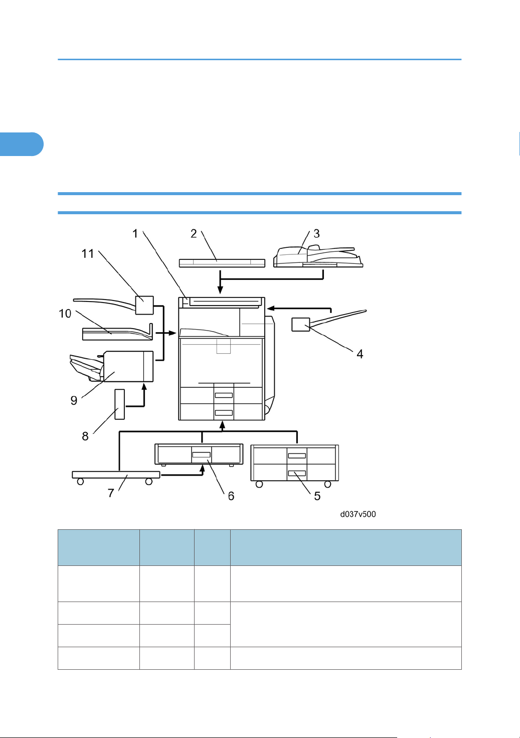
H-Model
20
Item
Mainframe
Platen cover G329 [2]
ARDF D366 [3]
Side tray D427 [4] -
Machine
Code
D038/
D041
Call
out
[1] D038: C1a, D041: C1c
Remarks
One from the two;
[3] is standard.
Page 23

Machine Configuration
1
Item
1-bin tray D426 [11]
Shift tray D428 [10]
Internal finisher D429 [9]
Punch unit: 2/3
holes
Punch unit: 2 holes D390-27 Requires [9].
Punch unit: 4 holes D390-31 Requires [9].
Two-tray paper
feed unit
One-tray paper
feed unit
Caster Table D448 [7]
Machine
Code
D390-17
D331 [5]
D425 [6]
Call
out
One of the following 4 choices: [9] only, [10] only, [11]
only, or [10]+[11]
Requires [9].
[8]
One from [5], [6], and [7];
The one-tray PFU [6] requires [7].
If neither [5] nor [6] is installed, install [7] if required by the
customer.
Remarks
Item Machine code Remark
USB2.0/SD Slot D422 -
Fax Option D432
Memory Unit Type B G578
Hand Set B433
Gigabit Ethernet G874
IEEE 1284 B679
Wireless LAN
D377-01, 02
(IEEE 802.11a/g)
Wireless LAN
D377-19
(IEEE 802.11g)
Bluetooth B826
SAF memory:
Requires the Fax Option.
For NA model only: Requires the
Fax Option.
You can only install one of these at
a time.
21
Page 24

1. Product Information
1
File Format Converter D377-04
Copy Data Security Unit B829 -
Optional Counter Interface Unit B870 -
Key Counter Bracket A674 -
Memory Unit Type I D435-01 (For printer function)
Printer Enhanced Option D435-03, -04, -05
PostScript 3 D435-09, -10, -11
Data Overwrite Security Unit D362
PictBridge M344
VM Card D430-01, 02, 03
HDD Encryption Unit D377-16
You can only install one of these in
SD slot 1 at a time
In SD card slot 2Browser Unit D430-05, 06, 07
22
Page 25
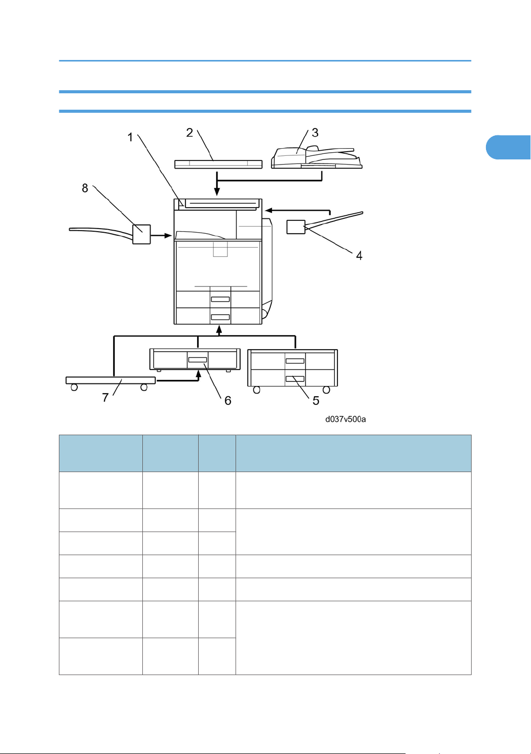
L-Model
1
Machine Configuration
Item
Mainframe
Platen cover G329 [2]
ARDF D366 [3]
Side tray D427 [4] -
1-bin tray D426 [8] -
Two-tray paper
feed unit
One-tray paper
feed unit
Machine
Code
D037/
D040
D331 [5]
D425 [6]
Call
out
[1] D037: C1La, D040: C1Lc
Remarks
One from the two;
[3] is standard for NA and EU
One from [5], [6], and [7];
The one-tray PFU [6] requires [7].
If neither [5] nor [6] is installed, install [7] if required by the
customer.
23
Page 26

1. Product Information
1
Item
Caster Table D448 [7]
Fax Option D433
Hand Set B433
Copy Data Security Unit B829 -
Optional Counter Interface Unit B870 -
Printer Enhanced Option D435-03, -04, -05
PictBridge M344
Machine
Code
Item Machine code Remark
Call
out
Remarks
For NA model only: Requires the
Fax Option.
You can only install one of these in
SD slot 1 at a time
24
Page 27

Overview
1
For "Overview" information, see "Appendices".
Overview
25
Page 28

1. Product Information
1
26
Page 29
2. Installation
2
Installation Requirements
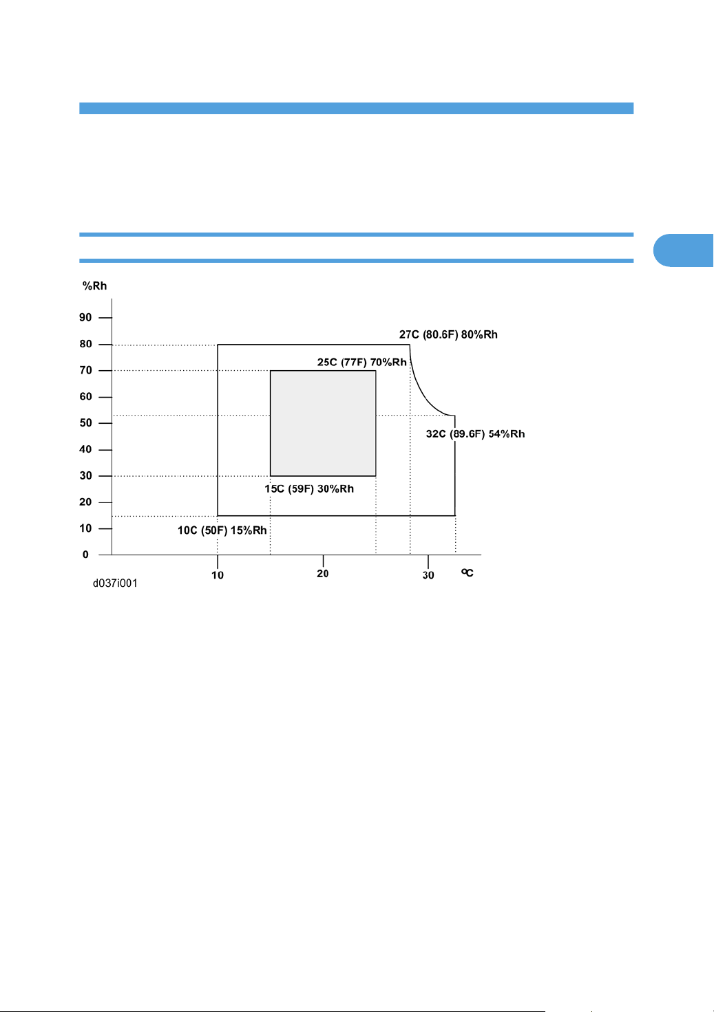
Environment
1. Temperature Range: 10°C to 32°C (50°F to 89.6°F)
2. Humidity Range: 15% to 80% RH
3. Ambient Illumination: Less than 1500 lux (do not expose to direct sunlight)
4. Ventilation: 3 times/hr/person or more
5. Do not let the machine get exposed to the following:
1) Cool air from an air conditioner
2) Heat from a heater
6. Do not install the machine in areas that are exposed to corrosive gas.
7. Install the machine at locations lower than 2,500 m (8,200 ft.) above sea level.
8. Install the machine on a strong, level base. (Inclination on any side must be no more than 5 mm.)
9. Do not install the machine in areas that get strong vibrations.
27
Page 30
2. Installation
2
Machine Level
Front to back: Within 5 mm (0.2")
Right to left: Within 5 mm (0.2")
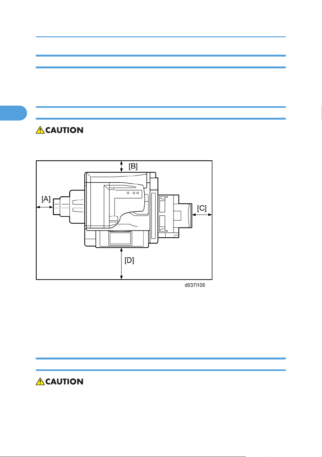
Machine Space Requirements
• This machine, which uses high voltage power sources, can generate ozone gas. High ozone density
is harmful to human health. Therefore, the machine must be installed in a well-ventilated room.
A: Over 100 mm (3.9")
B: Over 100 mm (3.9")
C: Over 100 mm (3.9")
D: Over 100 mm (3.9")
Put the machine near the power source with the clearance shown above.
Power Requirements
• Insert the plug firmly in the outlet.
• Do not use an outlet extension plug or cord.
28
Page 31

• Ground the machine.
2
1. Input voltage level:
• 120 V, 60 Hz: More than 12 A
• 220 V to 240 V, 50 Hz/60 Hz: More than 8 A
2. Permissible voltage fluctuation: ±10 %
3. Do not put things on the power cord.
Installation Requirements
29
Page 32

2. Installation
2
Optional Unit Combinations
Machine Options
Options
No.
D037/D040 D038/D041
1 2-tray paper feed unit 2-tray paper feed unit
2 1-tray paper feed unit 1-tray paper feed unit
3 Caster table Caster table
4 Platen cover Platen cover
5 ARDF ARDF (Standard)
6 1-bin tray unit 1-bin tray unit
Remarks
One from No.1 or No.2 (No.
2 requires No. 3)
One from No.4 or No.5
7 - Shift tray
8 Side Tray Side Tray
9 - Internal finisher
10 - *Punch kit (4 types)
11 Fax unit Fax unit -
12 - Memory Unit (32M)* Fax unit required
*: Child options (Child options require a parent option.)
If No 9 is installed, then No 6
and/or No 7 cannot be
installed.
No. 9 required; One of the
types
Controller Options
Options
No.
D037/D040 D038/D041
1 - IEEE 802.11a/g
2 - IEEE 1284
One from six items (I/F Slot)
Remarks
30
Page 33

3 - Bluetooth
2
4 - File Format Converter
5 - Gigabit Ethernet
6 - PostScript 3
7 Printer Enhanced Option -
8 PictBridge PictBridge
9 - DataOverwriteSecurity Unit
Optional Unit Combinations
One of these (SD card slot 1)
10 - HDD Encryption Unit
11 - Browser Unit
12 - VM Card SD card slot 2
13 Copy Data Security Unit Copy Data Security Unit -
14 - Memory Unit (512M) For SDK applications
SD card slot 2 (during
installation only)
SD card slot 2 (during
installation only)
31
Page 34

2. Installation
2
Copier Installation
Power Sockets for Peripherals
CAUTION
Rating voltage for peripherals.
Make sure to plug the cables into the correct sockets.
[1] ARDF: Rating voltage output connector for accessory Max. DC24V
[2] Finisher: Rating voltage output connector for accessory Max. DC24V
Installation Flow Chart
This flow chart shows the best procedure for installation.
32
Page 35

Copier Installation
2
*1: The shift tray should be installed first if you want to install the shift tray with the 1-bin tray at the same
time.
Accessory Check
Check the quantity and condition of these accessories.
For D037/D040
No. Description Q’ty Destination
1. Stamp 1 -17, -67
2. EU Safety Sheet 1
-67
3. WEEE 1
33
Page 36

2. Installation
2
No. Description Q’ty Destination
4. Certification 1
-21
5. Warranty Sheet (Chinese) 1
6. Operating Instruction – About this machine 1
7. Operating Instruction – Troubleshooting 1
8. Operating Instruction – Quick Reference Copy Guide 1
9. Operating Instruction – Quick Reference Fax Guide 1
10. Operating Instruction – Quick Reference Printer Guide 1
11. Operating Instruction – Quick Reference Scanner Guide 1
12. Operating Instruction – Quick Reference Printer & Scanner Guide
13. Operating Instruction – Manual for This Machine 1
14. Operating Instruction – Safety Information 1
15. CD-ROM Instruction – About this machine 1
16. CD-ROM Instruction – Troubleshooting 1
17. CD-ROM Instruction –Copy/Document Server Reference 1
18. CD-ROM Instruction –Facsimile Reference 1
19. CD-ROM Instruction –Printer Reference 1
20. CD-ROM Instruction –Scanner Reference 1
-17, -29, -21,
-19
-17, -67, -29,
-21, -19
-67, -29, -21,
-19
1 -17, -67, -29,
-21, -19, -28
-67
-17, -67, -29,
-21, -19
21. CD-ROM Instruction – Printer & Scanner Reference 1
22. CD-ROM Instruction – Network & General Setting Guide 1
23. CD-ROM Instruction – Security Reference 1
24. Printer Driver CD-ROM 1 -29, 28
25. Scanner Driver & Utility CD-ROM 1
-17, -67, -29
26. Clear Cover 1
34
Page 37

Copier Installation
2
For D038/D041
No. Description Q’ty Destination
1. Stamp 1 -57, -67
2. EU Safety Sheet 1
-67
3. WEEE 1
4. Certification 1
-21
5. Warranty Sheet (Chinese) 1
6. Operating Instruction – About this machine 1
7. Operating Instruction – Troubleshooting 1
8. Operating Instruction – Quick Reference Copy Guide
9. Operating Instruction – Quick Reference Printer Guide 1
10. Operating Instruction – Quick Reference Scanner Guide 1
11. Operating Instruction – Manual for This Machine 1
12. Operating Instruction – Safety Information 1
13. CD-ROM Instruction – About this machine 1
14. CD-ROM Instruction – Troubleshooting 1
15. CD-ROM Instruction –Copy/Document Server Reference 1
16. CD-ROM Instruction –Facsimile Reference 1
17. CD-ROM Instruction –Printer Reference 1
18. CD-ROM Instruction –Scanner Reference 1
-57, -29, -21,
-19
1 -67, -29, -21,
-19
-57, -67, -29,
-21, -19
-67
-57, -67, -29,
-21, -19
19. CD-ROM Instruction – Network & General Setting Guide 1
20. CD-ROM Instruction – Security Reference 1
21. PostScript 3 Supplement
22. Printer Driver CD-ROM 1 -29, 28
23. Scanner Driver & Utility CD-ROM 1
-67, -29, -21,
-19, -28
-57, -67, -29
35
Page 38

2. Installation
2
No. Description Q’ty Destination
24. Clear Cover 1
Installation Procedure
• Remove the tapes from the development units before you turn the main switch on. The development
units can be severely damaged if you do not remove the tapes.
Put the machine on the paper tray unit first if you install an optional paper tray unit at the same time. Then
install the machine and other options.
• Keep the shipping retainers after you install the machine. You may need them in the future if you
transport the machine to another location.
Tapes and Retainers
1. Remove all the tapes and retainers on the machine.
2. Remove all the tapes and retainers in trays 1 and 2.
36
Page 39

Copier Installation
2
3. Remove the scanner unit stay [A].
4. Keep the scanner unit stay in the cutout in the inner tray.
• For the EU models, the scanner unit stay cannot be inserted in the cutout on the inner tray. You
must bring this stay back to your depot.
5. Install the inverter tray [A] (hooks).
37
Page 40

2. Installation
2
6. Open the duplex unit [A].
7. Remove the sheet of paper [B].
8. Open the paper transfer unit [A].
9. Remove the front and rear stoppers [B] with a red tag.
10. Close the duplex unit.
38
Page 41

Copier Installation
2
11. Attach the handle cover [A] to the front side of the duplex unit.
Developer and Toner Bottles
1. Open the front door [A] and remove the PCDU toner collection bottle [B].
2. Remove all tapes except the tape [C] from the four development units and from the toner hopper units.
• Do not remove the tape [C] at this moment. You will find how to remove this tape later.
• The toner hopper cover [D] is removed with tape [E].
• Make sure that the all toner hopper covers are removed, when removing all tapes.
3. Check if the toner hopper shutter [A] is fully closed.
• If the toner hopper shutter is not fully closed and the inlet [B] of the toner hopper unit is visible,
the toner bottle cannot be installed properly.
39
Page 42

2. Installation
2
4. Press the ITB lock lever [A] and turn it up as shown above.
5. Remove the black PCDU [B] ( x 2).
6. Remove the cover sheet [A] from the black PCDU.
7. Reinstall the black PCDU into the mainframe ( x 2).
8. Reinstall the PCDU toner collection bottle.
9. Shake each toner bottle five or six times.
10. Slide the toner bottles in toner bottle cartridges, then turn each one to the right (clockwise).
11. Close the front door.
40
Page 43

Copier Installation
2
Paper Trays
1. Pull each paper tray [A] out. Then adjust the side guides and end guide to match the paper size.
• To move the side guides, first pull out the tray fully. Then push down the green lock at the rear
inside the tray.
Emblem and Decals
1. Attach the correct emblem [A] and the cover [B] to the front door [C] of the machine, if the emblem
is not attached.
• If you want to change the emblem that has been already attached, remove the panel with an
object (not a sharp object) as shown [D], and then install the correct emblem.
41
Page 44

2. Installation
2
2. Attach the correct paper tray number and size decals to the paper trays [E].
• Paper tray number and size decals are also used for the optional paper tray or the optional LCT.
Keep these decals for use with these optional units.
Fax Settings for D037-17
The D037-17 model has a fax unit as a standard function. Because of this, the fax settings are required at
machine installation. Refer to steps 7 to 9 and 14 to 16 in the "Fax Option (D432) Installation Procedure"
in the “Field Service Manual” of the fax option manual.
Initialize the Developer
1. Make sure that the platen or ARDF is closed and the main power is turned off.
2. Plug in the machine.
3. Turn the main power switch on. The machine automatically starts the initialization procedure. The Start
button LED () turns green when this procedure has finished.
4. Make copies of image samples (text, photo, and text/photo modes).
5. Do the Automatic Color Calibration process (ACC) for each mode (Copy mode, Printer 600 x 600
dpi, Printer 1800 x 600 dpi, and Printer 1200 x 1200 dpi) as follows ((Printer 1200 x 1200 dpi is
for D038/D041 only):
• 1) Print the ACC test pattern (User tools > Maintenance > ACC > Start).
• 2) Put the printout on the exposure glass.
• 3) Put 10 sheets of white paper on top of the test chart.
• 4) Close the ARDF or the platen cover.
• 5) Press “Start Scanning” on the LCD panel. The machine starts the ACC.
6. Check that the sample image has been copied normally.
7. Open the front cover.
42
Page 45

Copier Installation
2
8. Remove the instruction guide sheet [A], and make sure the SMC report [B] is stored as shown above.
Then replace the instruction guide sheet.
Settings Relevant to the Service Contract
Change the necessary settings for the following SP modes if the customer has made a service contract.
• You must select one of the counter methods (developments/prints) in accordance with the contract
(* SP5045-001).
Counting method
SP No. Function Default
Specifies if the counting method used in meter charge
SP5-045-001
mode is based on developments or prints. NOTE: You
can set this one time only. You cannot change the
setting after you have set it for the first time.
“0”: Developments
A3/11" x 17" double counting
SP No. Function Default
Specifies whether the counter is doubled for A3/11"
SP5-104-001
Service Tel. No. Setting
SP No. Function Default
SP5-812-001
through 004
x 17" paper. When you have to change this setting,
contact your supervisor.
5812-002 programs the service station fax number.
The number is printed on the counter list when the
meter charge mode is selected. This lets the user fax
the counter data to the service station.
“No”: Single counting
Settings for @Remote Service
• Prepare and check the following check points before you visit the customer site. For details, ask the
@Remote key person.
Check points before making @Remote settings
1. The setting of SP5816-201 in the mainframe must be "0".
43
Page 46

2. Installation
2
2. Print the SMC with SP5990-002 and then check if a device ID2 (SP5811-003) must be correctly
programmed.
• 6 spaces must be put between the 3-digit prefix and the following 8-digit number (e.g.
xxx______xxxxxxxx).
• ID2 (SP5811-003) and the serial number (SP5811-001) must be the same (e.g. ID2:
A01______23456789 = serial No. A0123456789)
3. The following settings must be correctly programmed.
• Proxy server IP address (SP5816-063)
• Proxy server Port number (SP5816-064)
• Proxy User ID (SP5816-065)
• Proxy Password (SP5816-066)
4. Get a Request Number
Execute the @Remote Settings
1. Enter the SP mode.
2. Input the Request number which you have obtained from @Remote Center GUI, and then enter [OK]
with SP5816-202.
3. Confirm the Request number, and then click [EXECUTE] with SP5816-203.
4. Check the confirmation result with SP5816-204.
Value Meaning Solution/ Workaround
0 Succeeded -
1 Request number error Check the request number again.
3 Communication error (proxy enabled) Check the network condition.
4 Communication error (proxy disabled) Check the network condition.
Proxy error (Illegal user name or
5
password)
6 Communication error Check the network condition.
8 Other error See "SP5816-208 Error Codes" below this.
Request number confirmation
9
executing
5. Make sure that the screen displays the Location Information with SP5816-205 only when it has been
input at the Center GUI.
Check Proxy user name and password.
Processing… Please wait.
6. Click [EXECUTE] to execute the registration with SP5816-206.
44
Page 47

7. Check the registration result with SP5816-207.
2
Value Meaning Solution/ Workaround
0 Succeeded -
1 Request number error Check the request number again.
2 Already registered Check the registration status.
3 Communication error (proxy enabled) Check the network condition.
4 Communication error (proxy disabled) Check the network condition.
Proxy error (Illegal user name or
5
password)
8 Other error See "SP5816-208 Error Codes" below this.
Request number confirmation
9
executing
Check Proxy user name and password.
Processing… Please wait.
Copier Installation
8. Exit the SP mode.
SP5816-208 Error Codes
Cause Code Meaning Solution/ Workaround
Obtain a Request Number
before attempting the Inquiry or
Registration.
Perform Confirmation before
attempting the Registration.
Check ID2 of the mainframe.
Make sure that "Remote
Service" in User Tools is set to
"Do not prohibit".
Execute registration.
Operation Error,
Incorrect Setting
-12002
-12003 Attempted registration without
-12004 Attempted setting with illegal entries
-12005 @Remote communication is
-12006 A confirmation request was made
Inquiry, registration attempted
without acquiring Request No.
execution of a confirmation and no
previous registration.
for certification and ID2.
prohibited. The device has an
Embedded RC gate-related
problem.
after the confirmation had been
already completed.
45
Page 48

2. Installation
2
Cause Code Meaning Solution/ Workaround
-12007 The request number used at
registration was different from the
one used at confirmation.
Check Request No.
Error Caused by
Response from
GW URL
-12008
-2385 Other error
-2387 Not supported at the Service Center
-2389 Database out of service
-2390 Program out of service
-2391
-2392 Parameter error
-2393 External RCG not managed
-2394 Mainframe not managed
-2395 Box ID for external RCG is illegal.
-2396
Update certification failed because
mainframe was in use.
Two registrations for the same
mainframe
Mainframe ID for external RCG is
illegal.
Check the mainframe condition.
If the mainframe is in use, try
again later.
Check the registration condition
of the mainframe
-2397 Incorrect ID2 format Check the ID2 of the mainframe.
-2398 Incorrect request number format Check the Request No.
Moving the Machine
This section shows you how to manually move the machine from one floor to another floor. See the section
“Transporting the Machine” if you have to pack the machine and move it a longer distance.
• Remove all trays from the optional paper feed unit.
46
Page 49

Copier Installation
2
Transporting the Machine
Main Frame
1. Do SP 4806-001 to move the scanner carriage from the home position. This prevents dust from falling
into the machine during transportation.
2. Make sure there is no paper left in the paper trays. Then fix down the bottom plates with a sheet of
paper and tape.
3. Do one of the following:
• Attach shipping tape to the covers and doors.
• Shrink-wrap the machine tightly.
• After you move the machine, Make sure you do the "Auto Color Registration" as follows. This
optimizes color registration.
• Do the "Forced Line Position Adj. Mode c" (SP2-111-3).
• Then do the "Forced Line Position Adj. Mode a" (SP2-111-1).
To check if SP 2-111-1 was successful, watch the screen during the process. A message is
displayed at the end. Also, you can check the result with SP 2-194-10 to -12.
• Make sure that the side fences in the trays are correctly positioned to prevent color registration
errors.
47
Page 50

2. Installation
2
Paper Feed Unit (D331)
Accessory Check
Check the quantity and condition of the accessories against the following list.
No. Description Q’ty
1 Paper Feed Unit 1
2 Screw - M4 x 10 4
3 Securing Bracket 2
Installation Procedure
• Unplug the machine power cord before starting the following procedure.
• The handles of the main machine for lifting must be inserted inside the machine and locked, unless
these handles are used for the installation or relocation of the main machine.
• You need two or more persons to lift the copier. The copier is highly unstable when lifted by one
person, and may cause human injury or property damage.
48
Page 51

• This installation procedure uses the following symbol.
2
• : Screws
1. Remove the strips of tape.
Paper Feed Unit (D331)
2. Set the copier [A] on the paper tray unit [B].
• When installing the copier, be careful not to pinch the cable [C].
3. Remove the connector cover [A] (rivet screw x 1).
4. Connect the cable [B] to the copier, as shown.
5. Attach a securing bracket [C] to each side of the paper tray unit, as shown ( x 1: M3 x 8 each).
6. Re-install the connector cover.
49
Page 52

2. Installation
2
7. Remove the 1st and 2nd paper trays [A] and secure the paper tray unit with two screws (M4 x 10)
[B].
8. Reinstall all the paper trays.
9. Attach the appropriate paper tray number decal and paper size decal to each handle of the trays.
• The paper tray number and size decal sheet is in the accessory box of the main machine.
10. Rotate the adjuster [A] until the machine cannot be pushed across the floor.
11. Load paper into the paper trays and select the proper paper size.
12. Turn on the main switch.
13. Adjust the registration for each tray (* p.157 "Image Adjustment").
• For tray 3, use SP1002-004
• For tray 4, use SP1002-005
14. Check the machine’s operation and copy quality.
50
Page 53

Paper Feed Unit (D425)
2
Component Check
Check the quantity and condition of the accessories against the following list.
No. Description Q’ty
1 Paper Feed Unit 1
2 Securing bracket 2
3 Screw (M4 x 10) 4
Paper Feed Unit (D425)
Installation Procedure
• Turn off the main switch of the copier and unplug the power cord before you start the installation
procedure.
• You need two or more persons to lift the copier. The copier is highly unstable when lifted by one
person, and may cause human injury or property damage.
• Do not lift the copier with the paper feed unit installed. The handle and grips may be damaged.
• The one-tray paper feed unit must be installed on the caster table (D448). Prepare the caster table
first before installing this unit.
51
Page 54

2. Installation
2
• This installation procedure uses the following symbols:
• : Screws
1. Remove all tape on the paper feed unit.
2. Remove the paper tray and remove all tapes and padding.
3. Put the paper tray unit on the caster table (D448).
• For details about the installation of the caster table, see the “p.54 "Caster Table (D488)"”
installation procedure.
4. Grasp the handle [A] and grips [B] of the machine.
52
Page 55

5. Lift the copier and install it on the paper feed unit [C].
2
• Hold the handle and grips of the machine when you lift and move the machine.
Paper Feed Unit (D425)
6. Remove the rear connector cover [A] of the main machine (rivet screw x 1).
7. Connect the harness [B] to the main machine.
8. Reinstall the rear connector cover [A] (rivet screw x 1).
9. Remove tray 1 and 2 of the machine.
10. Fasten the screws (M4 x 10) [C].
11. Reinstall all trays.
12. Attach the securing brackets [D] (M4 x 10; x 1 each).
13. Load paper into the paper feed unit.
14. Turn on the main power switch of the machine.
15. Adjust the registration for each tray (* p.157 "Image Adjustment").
• Use SP1002-004
16. Check the paper feed unit operation and copy quality.
53
Page 56

2. Installation
2
Caster Table (D488)
Component Check
No. Description Q’ty
1 Caster Table 1
2 Pin 2
3 Step Screw 2
Installation Procedure
1. Put the caster table on a flat place.
2. Install the two pins in the screw holes.
54
Page 57

Caster Table (D488)
2
• Use the screw holes [A] and [C] if the mainframe is directly installed on the caster table.
• Use the screw holes [B] and [C] if the one-tray paper feed unit (D425) is installed on the caster
table.
3. Grasp the handle [A] and grips [B] of the machine, if the copier is to be installed on the caster table.
• Hold the handle and grips of the machine when you lift and move the machine.
4. Lift the copier or one-tray paper feed unit [C], and then install it on the caster table [D].
5. Pull out tray 2 of the mainframe or the tray of the one-tray paper feed unit.
6. Secure the machine or one-tray paper feed unit to the caster table (step screw x 2)
55
Page 58

2. Installation
2
7. Reinstall the tray in the mainframe or one-tray paper feed unit.
8. Adjust the five leveling adjustors of the caster table.
56
Page 59

ARDF (D366)
2
Component Check
Check the quantity and condition of the components against the following list.
No. Description Q’ty
1 ARDF 1
2 Stamp Cartridge 1
3 Knob Screw 2
4 Stud Screw 2
5 Attention Decal – Top Cover 1
ARDF (D366)
Installation Procedure
• Unplug the copier power cord before starting the following procedure.
1. Remove all tapes and shipping retainers.
57
Page 60

2. Installation
2
2. Insert the two stud screws [A] on the top of the machine.
3. Mount the ARDF [A] by aligning the screw keyholes [B] of the ARDF support plate over the stud screws.
4. Slide the ARDF toward the front of the machine.
5. Secure the ARDF with the two knob screws [C].
58
Page 61

6. Install the stamp cartridge [A] in the ARDF.
2
ARDF (D366)
7. Peel off the platen sheet [A] and place it on the exposure glass.
8. Align the rear left corner (of the platen sheet) with the corner [B] on the exposure glass.
9. Close the ARDF.
10. Open the ARDF and check that the platen sheet is correctly attached.
59
Page 62

2. Installation
2
11. Attach the decal [A] to the top cover as shown. Choose the language that you want.
12. Plug in and turn on the main power switch of the machine, and then check the ARDF operation.
13. Make a full size copy. Check that the registrations (side-to-side and leading edge) and image skew
are correct. If they are not, adjust the registrations and image skew (see "p.157 "Image
Adjustment"" in the "Replacements and Adjustments" chapter).
60
Page 63

Platen Cover Installation (G329)
2
Platen Cover Installation (G329)
1. Install the stud screws [A] ( x 2) on the top cover as shown.
2. Position the platen cover bracket [B] on the heads of the stud screws, and slide the platen cover [C]
to the left.
61
Page 64

2. Installation
2
Side Tray (D427)
Component Check
Check the quantity and condition of the components against the following list.
No. Description Q’ty
1 Side Tray Paper Exit Unit 1
2 Side Tray 1
3 Decal: Push 1
4 Decal: Door Push 1
5 Screw: M3x8 1
6 Tray Stopper 1
62
Page 65

Installation Procedure
2
• Unplug the copier power cord before starting the following procedure.
1. Remove all tapes on the side tray.
Side Tray (D427)
2. Open the duplex unit [A].
3. Remove the right upper cover [B] ( x 2).
4. Close the side tray paper exit unit [A], and then connect the harness [B] to the machine.
5. Install the side tray paper exit unit ( x 2: removed in step 3).
63
Page 66

2. Installation
2
6. Install the side tray [A].
7. Lift the side tray, and then install the tray stopper [B] ( x 1: M3x8).
8. Attach the ‘Push door’ decal [A] to the top front edge of the duplex unit cover.
9. Close the duplex unit, and then attach the ‘Push’ decal [A] to the duplex unit cover.
64
Page 67

10. Turn on the main power switch of the machine.
2
11. Check the side tray operation.
Side Tray (D427)
65
Page 68

2. Installation
2
1-Bin Tray Unit (D426)
Component Check
Check the quantity and condition of the components against the following list.
No. Description Q’ty
1 Tray 1
2 1-Bin Tray Unit 1
3 Screw: Blue (M3 x 6) 1
4 Screw (M3 x 8) 1
5 Tray Support Bar 1
Installation Procedure
• Unplug the copier power cord before starting the following procedure.
66
Page 69

1-Bin Tray Unit (D426)
2
• If both the shift tray unit and the 1-bin tray unit are installed in the mainframe at the same time, install
the shift tray unit first. Installing the shift tray unit after the 1-bin tray unit may be difficult.
1. Remove all tapes.
2. Remove the inverter tray [A] (hook).
3. Open the right door [B] of the machine.
4. Remove the front right cover [C] ( x 1).
5. Remove the paper exit cover [A].
67
Page 70

2. Installation
2
6. Remove the connector cover [A] with a small flat screwdriver.
7. Remove the left frame cover [B] ( x 1).
8. Install the 1-bin tray unit [A] ( x 1: M3x6 blue, x 1).
9. Install the tray [A] (with the tray support bar) in the machine.
10. Attach the tray support cover [B] ( x 2: M3x8 in the accessories and one screw removed in step 7).
68
Page 71

1-Bin Tray Unit (D426)
2
11. Reassemble the machine.
12. Turn on the main power switch of the machine, and check the 1-bin tray unit operation.
69
Page 72

2. Installation
2
Shift Tray Unit (D428)
Component Check
Check the quantity and condition of the components against the following list.
No. Description Q’ty
1 Shift Tray Unit 1
Installation Procedure
• Unplug the copier power cord before starting the following procedure.
• If both the shift tray unit and the 1-bin tray unit are installed in the mainframe at the same time, install
the shift tray unit first. Installing the shift tray unit after the 1-bin tray unit may be difficult.
1. Remove all tapes.
70
Page 73

2. Remove the inverter tray [A] (hook).
2
3. Remove the output tray [B] ( x 2).
Shift Tray Unit (D428)
4. Put the shift tray [A] in the machine, and then connect the harness to the connector [B] on the inner
rear frame.
• If the shift tray is difficult to install in the mainframe, remove the paper exit cover [C] first ( x 1).
71
Page 74

2. Installation
2
5. Install the shift tray [A] fully in the machine ( x 2).
6. Reinstall the inverter tray.
7. Turn on the main power switch of the machine.
8. Check the shift tray unit operation.
72
Page 75

Internal Finisher (D429)
2
Internal Finisher (D429)
This procedure explains how to install the internal finisher, without installing the punch unit at the same time.
Component Check
Check the quantity and condition of the components against the following list.
No. Description Q’ty
1 Internal Finisher 1
2 Inverter Unit 1
3 Inner Bottom Plate 1
4 Screw: M3x10 3
5 Screw: M3x6 11
6 Guide Rail 1
7 Inverter Cover 1
8 Left Cover 1
73
Page 76

2. Installation
2
Installation Procedure
• Unplug the copier power cord before starting the following procedure.
Preparing before Installing the Internal Finisher
1. Remove all tapes from the internal finisher.
2. Remove the inverter tray [A].
3. Open the front door [B].
4. Remove the PCDU toner collection bottle [A].
5. Hold down the ITB lock lever [B] and turn it in the arrow direction.
6. Remove the inner right cover [A] ( x 2).
74
Page 77

7. Open the duplex unit [A], and then remove the front right cover [B] ( x 1).
2
Internal Finisher (D429)
8. Remove the following:
• Inner tray [A] ( x 2)
• Left frame rear cover [B] ( x 2)
• Left frame cover [C] ( x 1)
• Paper exit cover [D] ( x 1)
• Inner rear cover [E] ( x 1)
75
Page 78
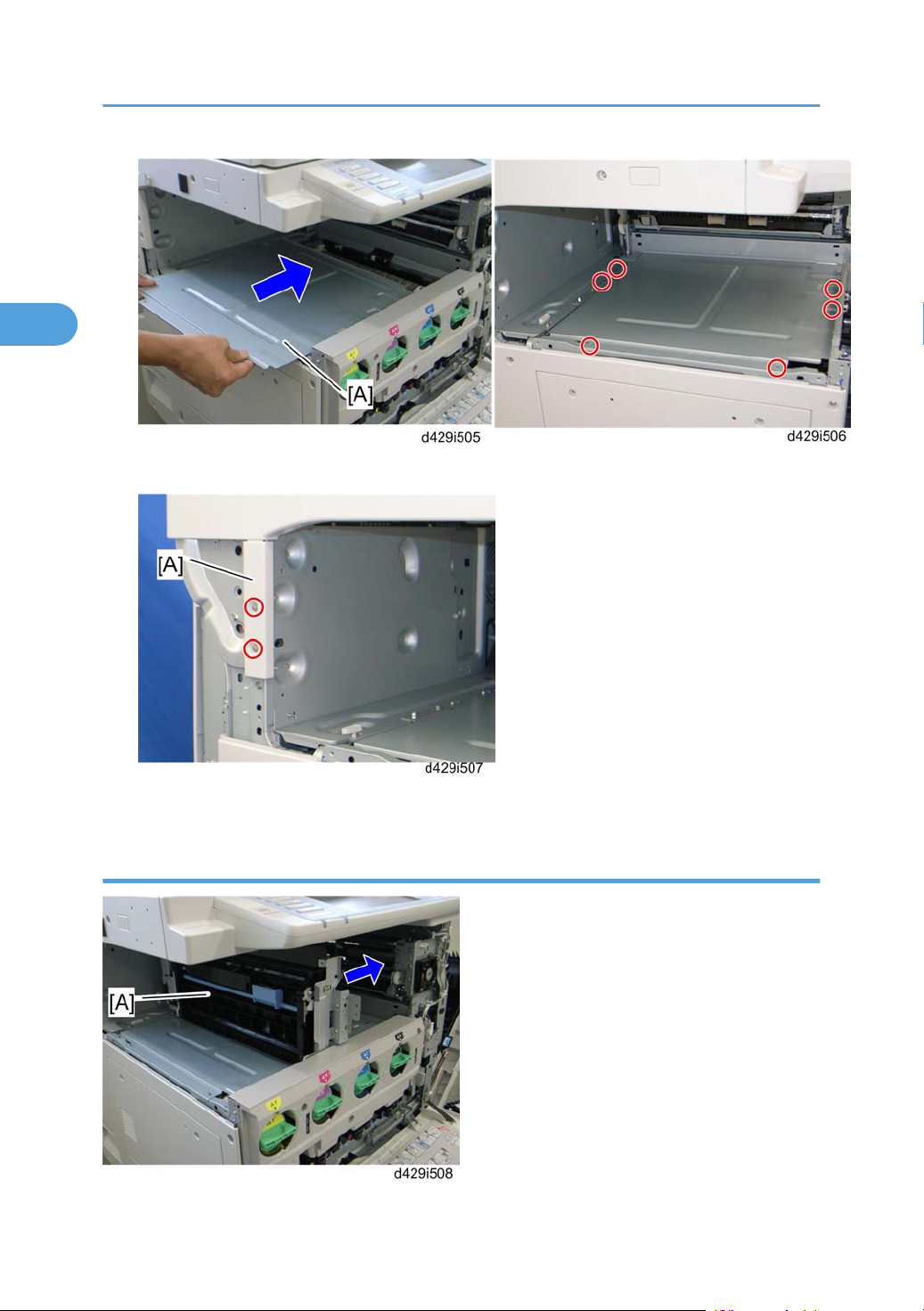
2. Installation
2
9. Install the inner bottom plate [A] ( x 6).
10. Attach the left cover [A] ( x 2: M3x6, one screw removed in step 8).
Internal Finisher Installation
76
Page 79

Internal Finisher (D429)
2
1. Insert the inverter unit [A] in the machine.
2. Insert two joint pins [A] into the two holes in the inner rear bracket.
3. Fully attach the front side [B] of the inverter unit to the paper exit unit of the mainframe after inserting
the two joint pins ( x 1: M3x6).
• Insert the two joint pins before attaching the front side of the inverter unit to the paper exit unit of
the mainframe. Otherwise, paper jams may occur between the paper exit unit and inverter unit.
4. Install the guide rail [A] ( x 2: M3x6).
77
Page 80

2. Installation
2
5. Attach the inverter cover [A] ( x 3: M3x10).
6. Install the internal finisher [A] from the left side of the machine.
7. Insert the rear rail pins [A] into the frame of the machine ( x 1: M3x6).
78
Page 81

Internal Finisher (D429)
2
8. Push the internal finisher [A] and connect the cable [B] to the power socket of the machine.
9. Reassemble the machine.
10. Turn on the main power switch of the machine.
11. Check the internal finisher operation.
79
Page 82

2. Installation
2
Punch Unit (D390)
Component Check
Check the quantity and condition of the components against the following list.
No. Description Q’ty
1 Punch Unit 1
2 Output Tray Lower Cover 1
3 Drawer Connector 1
4 Bracket 1
5 Left Frame Cover 1
6 Punch Cover 1
80
Page 83

Punch Unit (D390)
2
Installation Procedure
If the internal finisher has not already been installed, skip the ‘Removing the Internal Finisher’ section, and
go to the ‘Preparing the Punch Unit before Installing the Internal Finisher’ section. Also do ‘Preparing before
Installing the Internal Finisher’ in the ‘Internal Finisher (D429)’ section.
If the internal finisher has already been installed, you must remove it first. Start from the ‘Removing the
Internal Finisher’ section.
• Unplug the copier power cord before starting the following procedure.
Removing the Internal Finisher
1. Open the front door.
2. Open the right door [A], and then remove the front right cover [B] ( x 1).
3. Disconnect the cable [A] from the power socket of the machine, and then pull out the internal finisher
[B].
81
Page 84

2. Installation
2
4. Remove the internal finisher [A] ( x 1: M3x6).
82
5. Remove the inverter cover [A] ( x 3: M3x10).
6. Remove the guide rail [A] ( x 2: M3x6).
Page 85

7. Pull the inverter unit [A] toward the front side ( x 1: M3x6).
2
Punch Unit (D390)
8. Remove the inverter unit [A] from the machine.
Preparing the Punch Unit before Installing the Internal Finisher
83
Page 86

2. Installation
2
1. Remove the inverter right bracket [A] from the inverter unit ( x 4).
2. To remove screw [B], open guide plate [C].
3. Remove the positioning pin bracket [A] from the inverter right bracket ( x 2).
4. Attach the inverter right bracket [A] to the punch unit [B] ( x 1: M3x6).
84
Page 87

Punch Unit (D390)
2
5. Slide the inverter small guide [A] to the front side (arrow direction), and then remove it ( x 1).
6. Remove all the tapes on the punch unit.
• If all the tapes are not removed, SC763 may occur.
7. Attach the inverter unit [A] to the punch unit [B], and then secure the inverter unit with the punch unit
( x 4 removed in step 1).
8. Attach the drawer connector [A] of the punch unit to the rear bracket of the inverter unit ( x 2 removed
in step 3).
9. Attach the clamp [B] to the rear bracket of the inverter unit.
85
Page 88

2. Installation
2
Installing the Punch and Inverter Unit
1. Install the punch and inverter unit [A] in the mainframe.
2. Insert the two joint pins [A] (this picture does not show the two joint pins) into the two holes in the inner
rear bracket.
3. Fully attach the front side [B] of the inverter unit to the paper exit unit of the mainframe after inserting
two joint pins ( x 1: M3x6).
• Insert the two joint pins before attaching the front side of the inverter unit to the paper exit unit of
the mainframe. Otherwise, paper jams may occur between the paper exit unit and inverter unit.
86
Page 89

Punch Unit (D390)
2
4. Remove the stopper [A] from the guide rail, and then attach with the screw holes [B] (these screw
holes must be used when the internal finisher is installed with the punch unit).
5. Install the guide rail [A] on the front edge of the inner bottom plate ( x 2).
6. Install the punch cover [A] ( x 3: M3x6).
87
Page 90

2. Installation
2
Preparing the Internal Finisher
1. Remove the left rear cover [A] and the rear cover [B] of the internal finisher ( x 2 each).
2. Attach the drawer connector [A] to the rear bracket of the finisher.
3. Connect the harnesses [B] to the connectors [C] on the main board.
• Black harness connector to CN16
• Gray harness connector to CN17
4. Reinstall the rear cover (removed in step 1) ( x 2).
88
Page 91

Installing the Internal Finisher
2
1. Install the internal finisher [A] in the mainframe ( x 1).
Punch Unit (D390)
2. Remove the bracket [A] ( x 2).
3. Attach the bracket [A] ( x 2); this bracket is for the internal finisher when used with the punch unit.
89
Page 92

2. Installation
2
4. Remove the output tray lower cover [A]; this cover is for the internal finisher without the punch unit
( x 3).
5. Attach the output tray lower cover [A]; this cover is for the internal finisher when used with the punch
unit ( x 3).
90
Page 93

Punch Unit (D390)
2
Note
The two projections [A] on the output tray lower cover (this plate is actually attached to the output
tray lower cover) must be inserted along the two guide rails [B] inside the output tray unit.
Push the slide plate [A] to check if the output tray lower cover is correctly installed. The left side
picture shows the correct result and the right side picture shows the incorrect result.
6. Attach the left frame cover [A] ( x 2).
91
Page 94

2. Installation
2
7. Push the internal finisher in the mainframe.
8. Connect the I/F cable [B] of the finisher to the inlet of the mainframe.
92
Page 95

USB2.0/SD Slot Type A
2
Accessory Check
Check the quantity and condition of the accessories against the following list.
No. Description Q’ty
1 USB2.0/SD Slot 1
2 Ground Plate 1
3 USB Cable 1
4 Screw: M3 x 6 blue 1
5 Screw: M3 x 8 4
6 Decal 1
USB2.0/SD Slot Type A
Installation Procedure
1. Connect the USB cable [B] to the USB slot [A] in the USB2.0/SD Slot unit.
2. Attach the ground plate [C] to the bracket of the USB2.0/SD Slot ( x 1: M3x6 blue).
93
Page 96

2. Installation
2
3. Remove the screw [A] first, and the rear cover [B] ( x 7).
4. Remove the scanner left cover [A] ( x 2).
5. Remove the left frame cover [B] ( x 2).
6. Remove the part [A] on the scanner left cover.
94
Page 97

7. Make four holes in the scanner left cover with a screwdriver as shown [A].
2
• Smooth the four holes in the scanner left cover as shown [B].
USB2.0/SD Slot Type A
8. Route the USB cable [A] through the gaps in the left scanner cover.
9. Secure the USB2.0/SD Slot [B] with the left scanner cover as shown above ( x 4: M3x8).
• Use the screw holes [C] as shown above.
95
Page 98

2. Installation
2
10. Attach the scanner left cover [A] to the mainframe, and then connect the USB cable [B] to USB-A (this
is the USB slot closest to the front side of the machine) as shown above.
• Make sure that the USB cable is inserted in USB-A (front side).
11. Plug in and turn on the mainframe.
12. Enter the SP mode, and then change the setting of SP1013-001 from “0” to “1”.
13. Attach the decal [A] to the USB2.0/SD Slot as shown above.
Testing the SD Card/USB Slot
1. Insert an SD card or USB memory device in the slot.
You can connect only one removable memory device at a time.
1. Close the media slot cover.
96
Page 99

USB2.0/SD Slot Type A
2
If you leave the cover open, static electricity conducted through an inserted SD card could cause the
machine to malfunction.
1. Make sure that no previous settings remain.
If a previous setting remains, press the [Clear Modes] key.
1. Place an original on the exposure glass.
2. Press [Store File].
3. Press [Store to Memory Device].
4. Press [OK].
5. Press the [Start] key.
When writing is complete, a confirmation message appears.
1. Press [Exit].
2. Remove the memory device from the media slot.
Do not remove the memory device while writing is in process.
97
Page 100

2. Installation
2
Mechanical Counter (NA Only)
• This counter is supplied as a spare part.
Installation Procedure
1. Rear cover (* p.172 "Rear Cover" in the "Replacement and Adjustment" section)
2. Rear lower cover (* p.172 "Rear Lower Cover" in the "Replacement and Adjustment" section)
3. Controller box cover (* p.300 "Controller Box Cover " in the “Replacement and Adjustment” section)
4. Remove the cutouts [A] in the rear lower cover with nippers.
5. Attach the mechanical counters [A] to the bracket [B] and connect the harness to each mechanical
counter as shown above.
98
 Loading...