

Page 1
NOTICE
This equipment has been tested and found to comply with the
limits for a Class B digital device, pursuant to part 15 of the
FCC Rules. These limits are designed to provide reasonable
protection against harmful interference in a residential
installation. This equipment generates, uses and can radiate
radio frequency energy and, if not installed and used in
accordance with the instructions, may cause harmful
interference to radio communication. However, there is no
guarantee that interference will not occur in a particular
installlation. If this equipment does cause harmful interference
to radio or television reception, which can be determined by
turning the equipment off and on, the user is encouraged to try
to correct the interference by one or more of the following
measures:
● Reorient or relocate the receiving antenna.
● Increase the separation between the equipment and
receiver.
● Connect the equipment into an outlet on a circuit different
from that to which the receiver is connected.
● Consult the dealer or an experienced radio / TV technician
for help.
Warning as to USE
This CD-R/RW & DVD-ROM drive together with software is a
product for utilizing CD-R/RW recording media with rewriting,
erasing and readout capabilities, as an external computer
memory device. Except in the case where copying of
CD-ROMs or the like is especially recognized under the
copyrights laws as being for the purpose of individual use by
the customer or the like, or in the case where the customer has
obtained permission to make copies from the rightholder,
reproduction of CD-ROMs and copyright laws. Take notice that
unauthorized copying may be subject to claims for damages
and to penalties.
Page 2
CAUTION
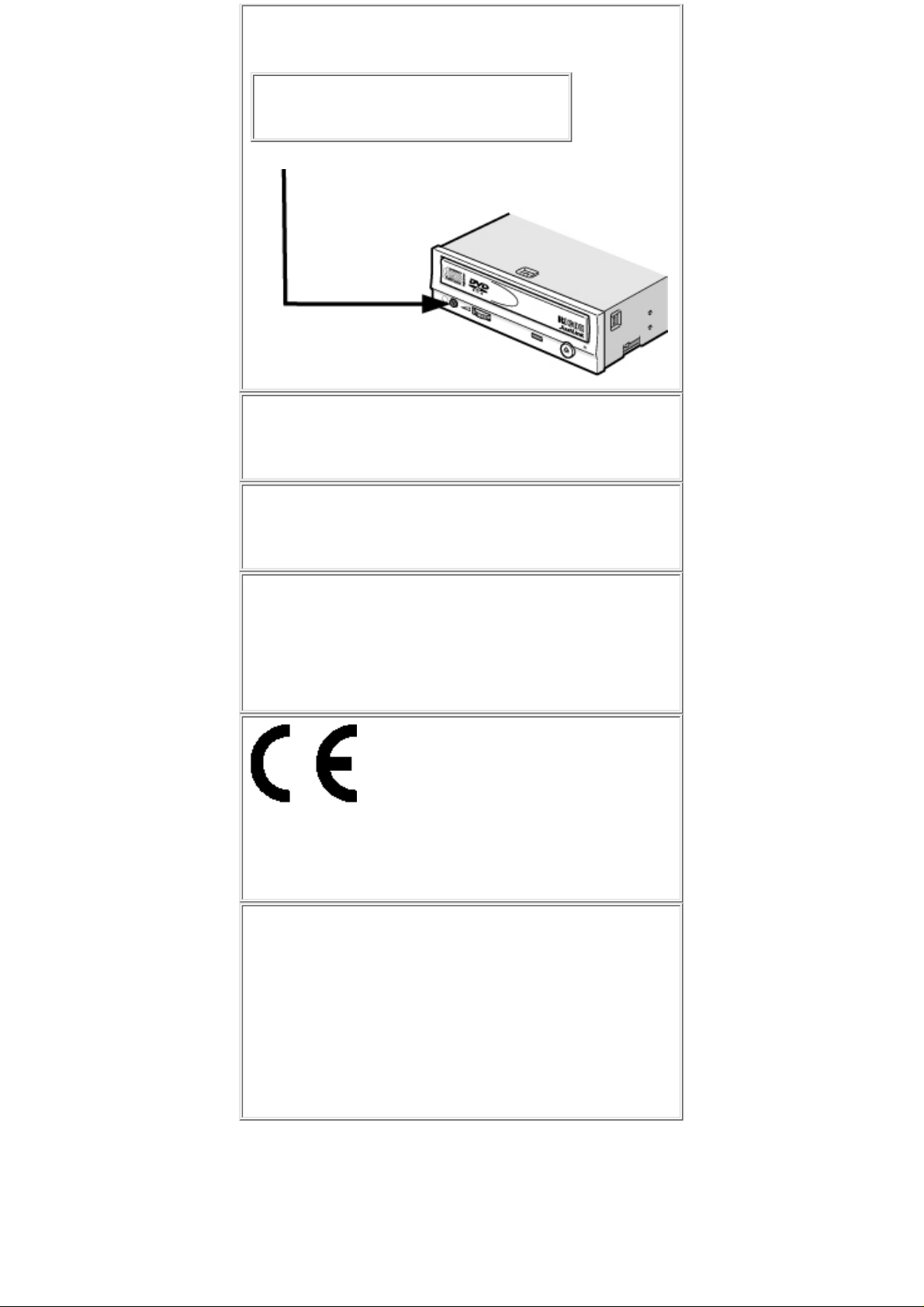
Rating voltage for peripherals.
1. Headphone Jack
Rating Voltage output Audio Signal Max. 2V
FCC WARNING
Changes or modification not expressly approved by the party
responsible for compliance could void the user's authority to
operate the equipment.
CAUTION
Use of controls or adjustments or performance of procedures
other than those specified herein may result in hazardous
radiation exposure.
Lower a volume
Use of controls or adjustments or performance of procedures
other than those specified herein may result in hazardous
radiation exposure.
The volume that exceeds 70dB occurs and the obstacle
sometimes breaks out.
Declaration of Conformity
"The Product complies with the requirements of the EMC
Directive 89/366/EEC and the Low Voltage Directive
73/23/EEC."
Please take notice that the manufacturer of this
equipment does not offer any warranty against data loss
due to inappropriate installation or handling, or direct or
indirect damages.
●
Please take notice that the manufacturer will bear no
responsibility for direct or indirect damages caused by
the use of this product or its malfunction.
●
Please take notice that the manufacturer will bear no
responsibility for damage to data caused by this product.
●
Please backup (copy) all important data as protection
against data loss.
●
PC DOS is a trademark of IBM Inc.●
MS-DOS, Windows, Windows ® 95, Windows ® 98, Windows ® Me, Windows NT® and
Windows® 2000 are trademarks registered in the United States and other countries by the
Microsoft Corporation.
●
The company names and product names written in this manual are trademarks or registered
trademarks.
●
Page 3
This manual uses the following symbols to indicate important information relating to the drive.
Failing to comply with the information in this manual and/or incorrect handling of the drive
may result in serious personal injury or damage to the product.
Indicates restriction or precaution that should be observed.
Provides useful additional information.
Page 4
This manual contains important notes and product handling information. Be sure to read the
manual before using the product. For easy reference in the future, please keep the manual
at a handy location.
Multimedia Printer series
Thank you for purchasing the Multimedia Printer series drive MP9200A (hereafter referred to as the
drive). The drive enables you to play DVD-ROM or CD-ROM discs, write once and play CD-R discs, or
write, play, and rewrite CD-RW discs.
The following marks indicate media that can be used with the drive.
A new technology called Just Link incorporated
that overcomes buffer underrun problems
Buffer underrun errors that would occur when data transfer falls behind writing operation has been
inevitable for CD-R/RW drives. Just Link, which we at Ricoh developed on our own, is a new
technology that predicts possible occurrences of buffer underrun errors in advance and automatically
avoids them. The MP9200A is the industry's first-ever drive that features Just Link. With this
technology, the MP9200A ensures stable writing operation even under circumstances where buffer
underrun errors tend to occur with conventional drives.
New technology: (Optimum Write
Speed Control) function
When any write speed greater than 12X is specified, this function checks the media's capability to see
if it can be written at above-12X speeds. If the media is not capable of such speeds, the write speed is
reduced to 16X or 12X.
Page 5

Caution
The JustSpeed (Optimum Write Speed Control) function is set to ON by default.
Depending on the ON/OFF setting of this function, the write speed is controlled as specified
below.
When the speed control is ON
Writing is performed at the speed of 16X in the lead-in area, at 16X from the 0-minute
position up to around the 5-minute position, and then accelerating up to 20X
approximately from the 5-minute position to the 15-minute position.
●
When the speed control is OFF
Writing is performed at the speed of 12X in the lead-in area, at 16X from the 0-minute
position up to around the 10-minute position, and 20X from around the 10-minute
position and after.
●
Page 6
Obey the following cautions when handling the drive or discs.
Cautions During Installation
Install the drive in accordance with the specifications. Be careful to avoid locations
likely to cause vibration or shock.
●
Avoid locations where there is high humidity, excessive dust, or poor ventilation.●
Avoid locations in direct sunlight, with severe changes in humidity, or places where
there are extremely high or low temperature variations.
●
Don't use the drive near radio or television receivers. It may interfere with their
reception.
●
Do not disassemble the drive. Dismantling the drive to attempt repairs or for other
reasons is dangerous because the laser may radiate outside the unit.
●
Cautions During Use
Don't suddenly move the drive from a cold place to a warm place, or suddenly raise the
room temperature. Condensation may occur, causing abnormal operation.
●
Make sure to remove the disc before moving the drive. The disc may be damaged,
causing data loss.
●
Be careful to prevent foreign objects such as liquids or metal from entering the drive.
Should by chance a foreign object enter the drive, please consult the dealer where the
drive was purchased.
●
Don't use benzene or thinner to clean dirt from the drive. Don't allow chemicals such
as insecticides to contact the drive. Use a soft cloth to wipe the drive, or moisten a
cloth with neutral detergent diluted with water and use it to clean particularly dirty
areas.
●
Don't cutoff the electric power while the drive is operating.●
When connecting two E-IDE devices to the Primary or Secondary connectors, make
sure that the two devices are not both configured as Master, or both as Slave. If they
are both set the same, Windows may fail to run or recognize the drives.
●
The total length of the E-IDE cable should be less than 18 inches (about 45 cm).●
Make sure the power to the host computer is turned OFF before connecting.●
Never insert a damaged disc into the drive.●
In wintertime, don't use a disc soon after bringing in from outdoors. Use it only after it●
Page 7

has reached room temperature.
Cautions Concerning Disc Cleaning
Remove the disc by pressing the eject button.●
Use compressed air to clear dust from the disc. (Spray the compressed air for about 5
seconds).
●
Check to see if there is dirt on the surface of the disc. Be careful not to touch the disc
with the fingers when doing this. (See Fig. 1)
●
After cleaning the disc with compressed air, place it on the disc tray and mount it.(See
Fig. 2)
●
We suggest using dry air cleaner as compressed air for cleaning.●
Other Cautions
When moving the equipment, make sure that the disc has been removed from the
drive.
●
When connecting connectors, make sure that the power is OFF. If the power is ON,
there is a possibility of short circuit.
●
When not using the drive for a long period, dust may adhere to the disc tray. Before
using the drive again, use dry air cleaner to remove the dust from the tray.
●
Do not use any commercially available cleaning kit, because such a kit may damage
the drive.
●
Page 8
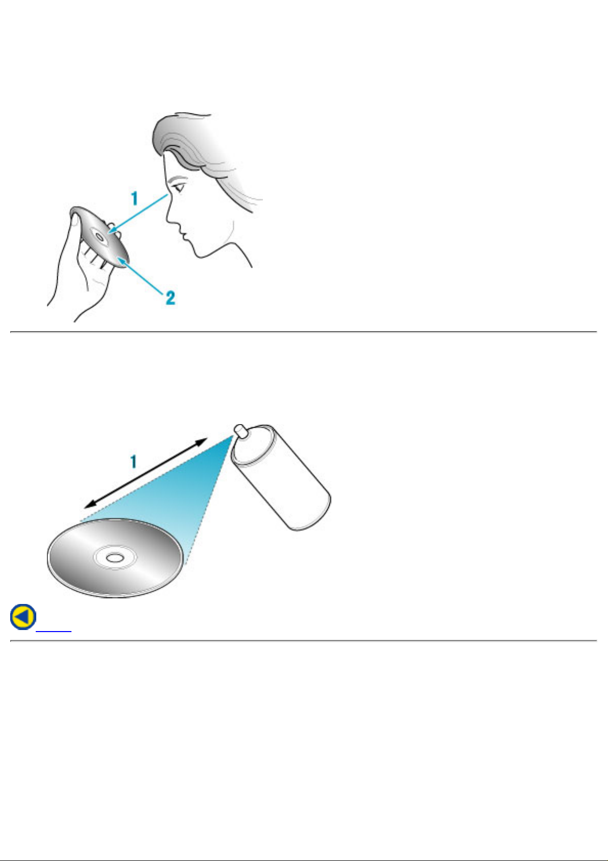
fig1
Check1.
Recording surface2.
fig2
50 to 100mm1.
Back
Page 9

JustLink has made auto-avoidance against buffer underrun
errors possible.
●
JustSpeed offers optimum write speed control that matches
the CD-R media.
●
An improved anti-heat design means that no cooling fan is needed.●
Easy-to-use tray model.●
Enhanced-IDE (ATAPI) model●
Compliant with industry standard Orange Book Part II (CD-R) and Part III (CD-RW).●
Can read not only CD-R and CD-RW discs, but also video CDs, music CDs, photo
CDs*1, and CD-Text
●
Can read data at 40x speed (6.0MB/sec data transfer rate), write data at 20x speed
(CD-R, 3.0MB/sec data transfer rate.) and write data at 10x speed *2(High Speed
CD-RW, 1.5MB/sec data transfer rate).
●
The recorded CD-RW media can be played in a DVD player or a multi-read CD-ROM
Player, maintaining future compatibility.
●
Supports random UDF for easy writing to CD-RW discs.●
UDMA-capable
*1
Bundled software does not support this writing format.
*2
The speed at which to write on the current standard CD-RW discs is 4x
recording (at a data transfer rate of 600KB/second).
●
Page 10
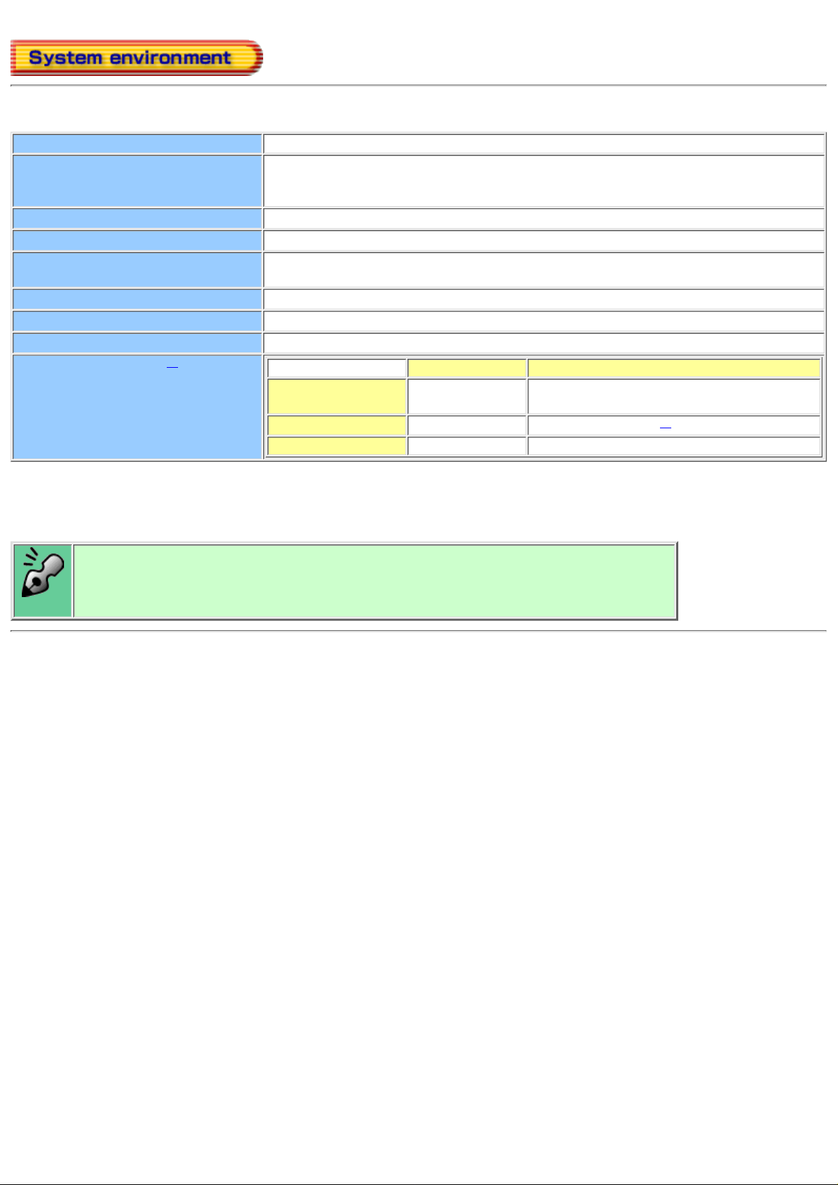
Explains the system environment required for using the drive as a CD-R/CD-RW drive.
PC IBM PC/AT compatible
Operating System Windows Me/98/95(ORS2 or later)
Windows NT Workstation Ver.4.0 (Service Pack 5) or later
Windows 2000 (Professional)
CPU Pentium 166 MHz or higher (When using JustLink)
Memory 64MB or more
Hard disk Hard disk with average access time of 19msec or less, and data transfer speed of
1,200KB/sec or greater. 1GB or more free space.
Interface Enhanced-IDE interface (as Primary Slave, Secondary Master, or Slave)
Drive bay 5.25-inch half height bay required
Power +5V/+12V power socket required
Recommendation discs
*2
Recommendation Tested to be compatible
CD-R Ricoh
Taiyo Yuden, Mitsui Chemicals, Mitsubishi
Chemical, Maxell
CD-RW Ricoh
Mitsubishi Chemical
*1
High Speed CD-RW Ricoh Mitsubishi Chemical
*1 The disc written using the CD-R/RW drive may not be readable by CD-ROM drives.
Multi-read compatible (Random UDF compatible) drives are necessary.
*2
Even if it is the recommendation disc, some of discs may have possibility to fail
writing with highest writing speed with the problem on the disc. In this case, please
try to write with lower writing speed, or please try to use another disc.
Multi-read compatible (Random UDF compatible) drives are:
Drives that can read low reflectivity discs.●
Drives that support Packet Write.●
Page 11
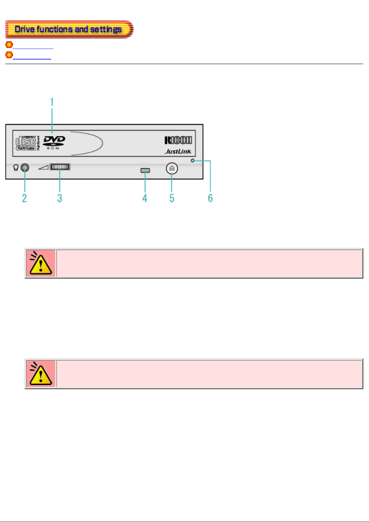
Front Panel
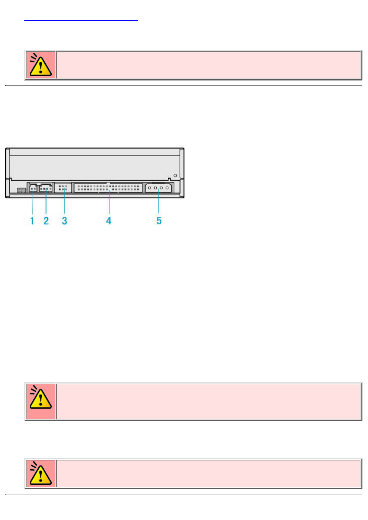
Rear panel
Front Panel
Disc tray
This is the tray for the disc. Place the disc on the ejected disc tray, then lightly push the tray (or push
the eject button) and the disc will be mounted.
Caution
Don't use force to pull out or push in the disc tray. This might cause damage to the
loading section of the drive.
1.
Headphone jack
This jack is for connecting headphones or mini-speakers.
2.
Volume control
This is used to adjust the output volume of the headphone jack. It can't be used to adjust the output
volume for the audio output connectors on the rear panel.
Caution
Turn the volume down before turning on the power. Sudden loud noises can damage
your hearing.
3.
Busy indicator
This indicator lights orange when a disc is mounted into the drive. When the disc is being accessed, it
flashes or lights orange. If a disc is not mounted, the indicator does not light even when the power is
turned on. When a illegal disc is loaded or some hardware trouble occurs, the indicator blinks.
4.
Eject button
This is the button used to eject or insert in the disc tray.
5.
Page 12
Emergency eject hole
This drive has a function that allows the disc to be ejected manually for an emergency case such as
failure of the drive or a power outage.
Caution
This feature is a last measure to be used only in an emergency. Using it excessively
will cause malfunction.
6.
Rear panel
Digital Audio (SPDIF) Output Connector
Provides output to a sound card (Digital signal).
* No digital audio cable is included with the MP9200A.
1.
Analog Audio Output Connector
Provides output to a sound card (Analog signal).
2.
Jumper Connector
This jumper determines whether the drive is configured as a master or slave. Changing the
master-slave configuration takes effect after power-on reset.
3.
IDE Interface Connector
Connect to the IDE (Integrated Device Electronics) interface using a 40-pin flat IDE cable.
Caution
Do not connect or disconnect the cable when the power is on, as this could cause a
short circuit and damage the system. Always turn the power OFF when connecting or
disconnecting the cable.
4.
Power Connector
Connects to the power supply (5 and 12V DC) of the host computer.
Caution
Be careful to connect with the proper way.
Connecting the wrong way may damage the system (and is not guaranteed).
5.
Page 13
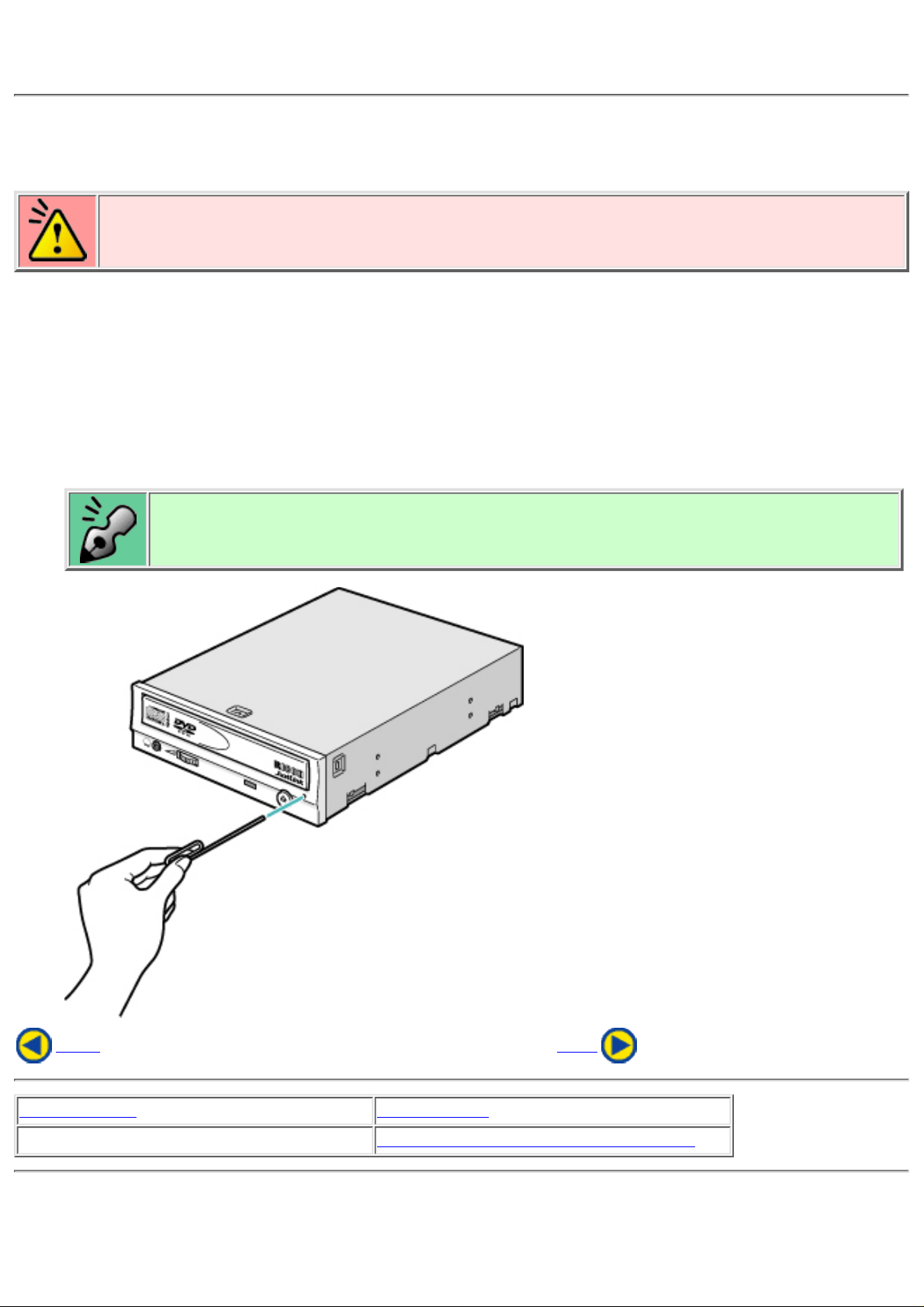
Emergency Eject
This drive has a function that allows the CD to be ejected manually, if this becomes necessary in an
emergency such as failure of the drive or a power outage.
Follow the following procedures in such a case.
Caution
This feature is a last measure to be used only in an emergency. Using it excessively will
cause malfunction.
Turn the power to OFF.1.
Insert a fine tipped object into the emergency eject hole.
The front door pops open and the disk tray comes partway out.
2.
Pull the front door to open it all the way,
then grip the disc tray between thumb and forefinger and gently pull it
straight out.
If you cannot get a good grip on the disc tray with your fingers, use a steel binder clip
or spring clamp to pull it out.
3.
Back Next
Load the disc Disc ejection
Emergency Eject
Using the Drive in a Vertical Position
Page 14
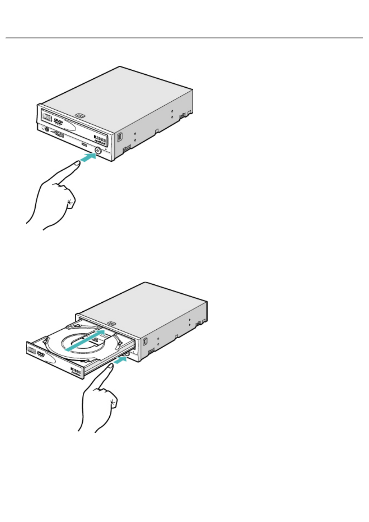
Disc ejection
Press the eject button1.
Slowly take the disc out of the disc tray2.
Press the eject button or push the disc tray and the tray will be inserted back
into the drive.
3.
Page 15
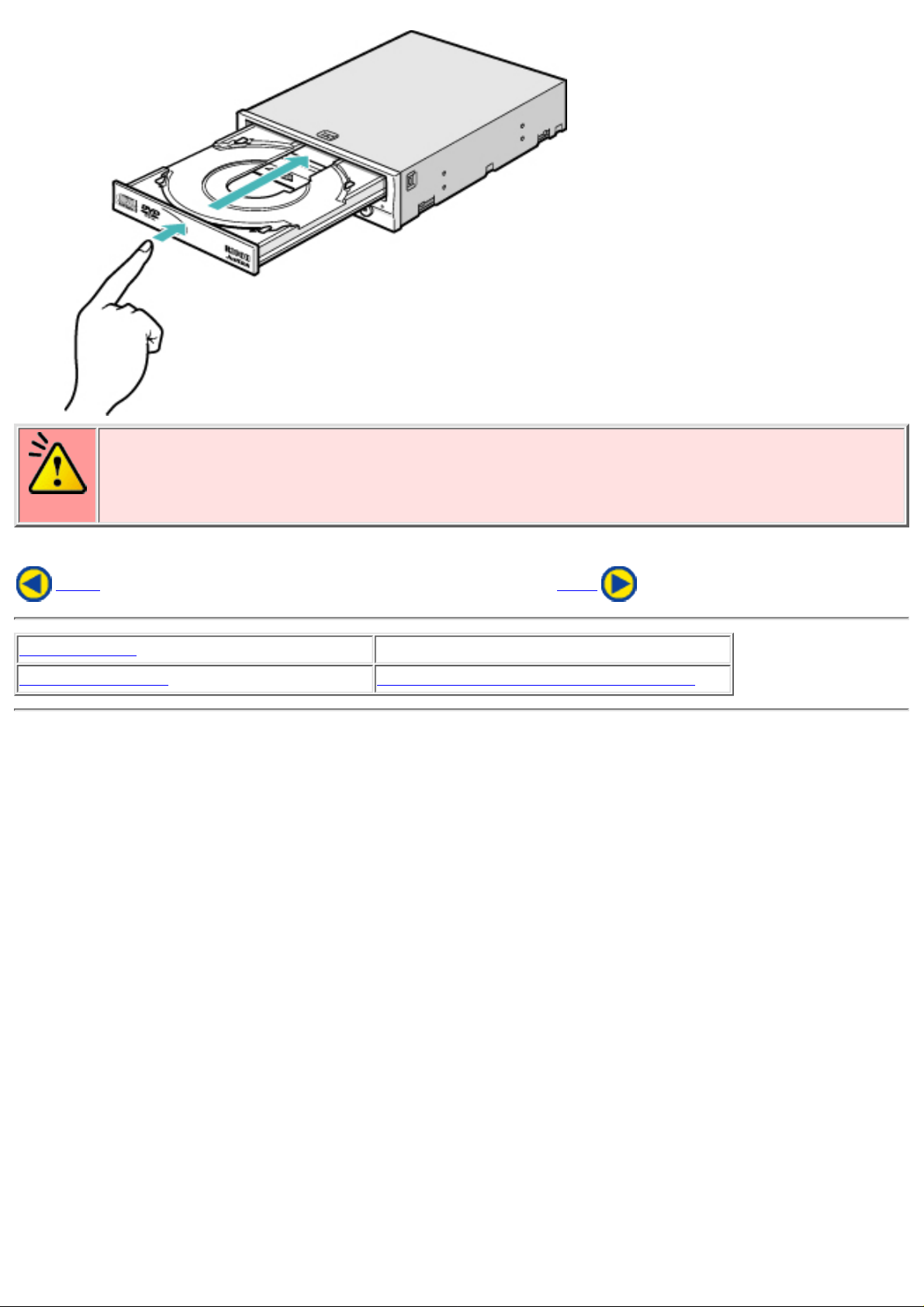
Caution
After ejecting the disc, return the disc tray inside the unit quickly. When the disc tray is in
the ejected position, dust and other debris will enter, possibly causing read errors, write
errors, or drive failure.
Back Next
Load the disc
Disc ejection
Emergency Eject Using the Drive in a Vertical Position
Page 16
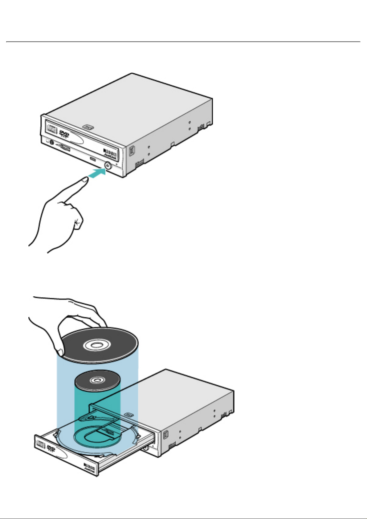
Load the disc
Press the eject button.1.
Place the disc on the disc tray.
Be careful not to touch the recording surface of the disc.
2.
Load the disc by pressing the eject button or by lightly pushing in the3.
Page 17
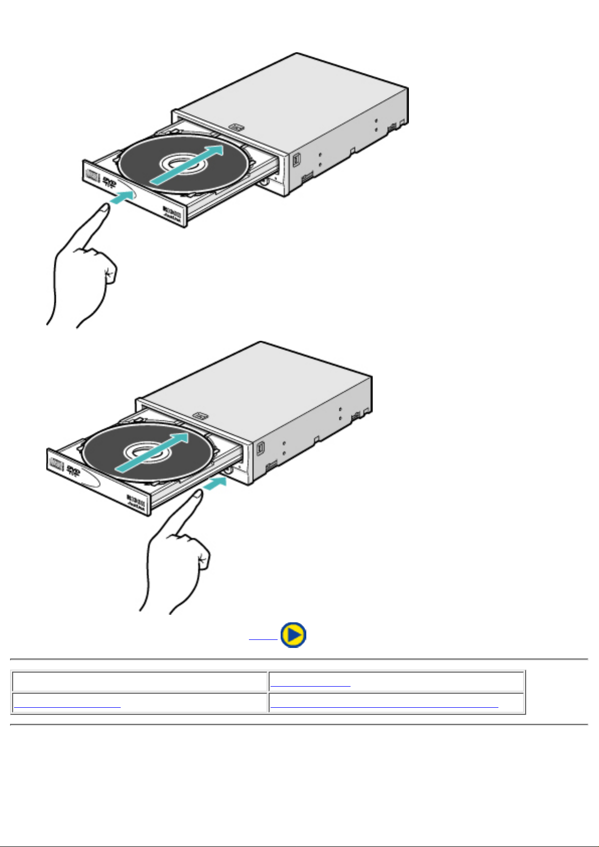
disc tray.
Next
Load the disc
Disc ejection
Emergency Eject Using the Drive in a Vertical Position
Page 18
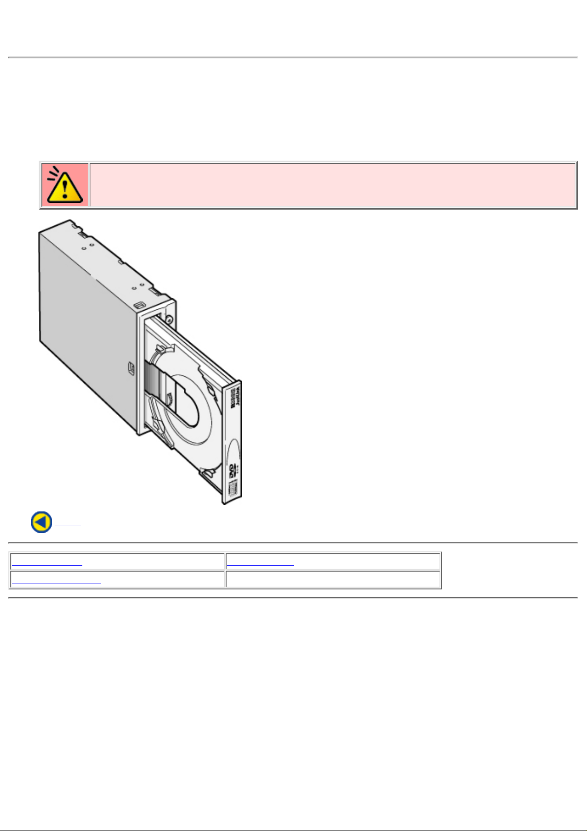
Using the Drive in a Vertical Position
The drive can be installed in a vertical position.
Locate the four tabs on the disc tray.
Turn each of them inwards untill they click into place.
1.
When loading a disc, insert it into the inner side of the tabs.
Caution
Cannot be used with 80mm CDs.
Cannot be used with business card CDs.
2.
Back
Load the disc Disc ejection
Emergency Eject
Using the Drive in a Vertical Position
Page 19
Specific knowledge of hardware and software is necessary to install the drive. We cannot
guarantee against direct or indirect damage resulting from improper connections. Ask your
supplier for details of the installation procedure.
Before Installation
Before installing the drive, please note the following points.
You will need the following:
A Phillips head screw driver of a suitable size to fit the securing screws for the drive unit.❍
The manual for the computer, to know the location of the IDE connector.❍
●
Turn off all peripheral devices of the computer, and the computer itself, and disconnect their
power cords from the wall sockets.
●
Discharge any static electricity by touching the computer covers etc.●
Before installing the drive, be sure to read the following cautions and information on preparation.
Keep a serial number label at the location specified by "READ ME FIRST".
●
Installing the Drive
Jumper Set Up1.
Removing the Computer Cover2.
Mounting the Drive3.
Connecting the Power Connector4.
PC Connections5.
Sound Card Connection6.
Replacing the Computer Cover7.
Device Drivers8.
Page 20
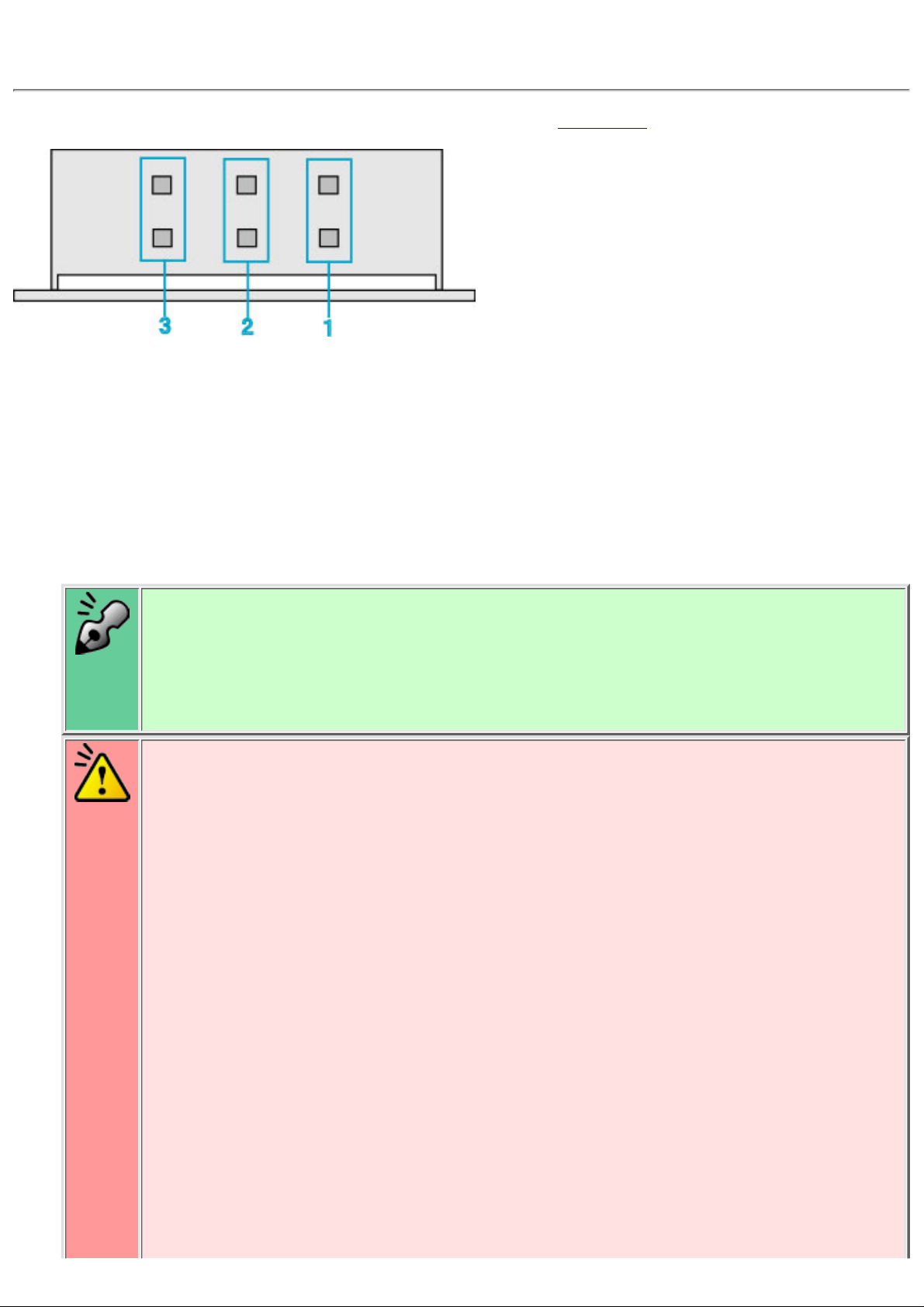
1. Jumper Set Up
Before installation, set the jumper on the jumper connector on the rear panel.
Master (MA)
Drive set as Master (factory default)
1.
Slave (SL)
Drive set as Slave
2.
Cable Select (CS)
Drive mode set by CSEL on the host IDE interface
3.
The drive can be connected as the Master or Slave on an E-IDE (ATAPI) interface.●
When several (up to four) E-IDE devices are connected, each must be set in a unique
way.
●
A hard disk is normally installed as the Primary Master on the E-IDE (ATAPI)
interface. Other E-IDE peripheral devices such as hard drives and CD-ROMs are then
set accordingly.
●
Caution
If two peripheral devices with the same settings are both connected to the Primary or
to the Secondary E-IDE bus, the host computer may fail to run, or may malfunction,
so careful attention is necessary.
●
Make sure that the host computer is turned OFF when connecting or removing a
jumper.
●
Must be connect the jumper in the vertical direction. If connected horizontally, the
drive may malfunction or be damaged.
●
Page 21
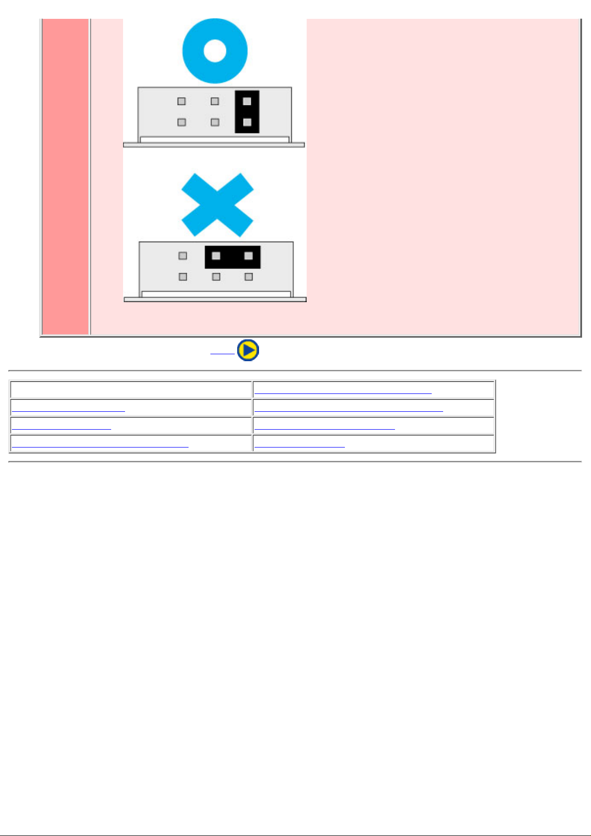
Only one jumper should be installed on the jumper connector. If more than one
jumper is installed, the drive may malfunction or be damaged.
●
Next
1. Jumper Set Up
2. Removing the Computer Cover
3. Mounting the Drive 4. Connecting the Power Connector
5. PC Connections 6. Sound Card Connection
7. Replacing the Computer Cover 8. Device Drivers
Page 22
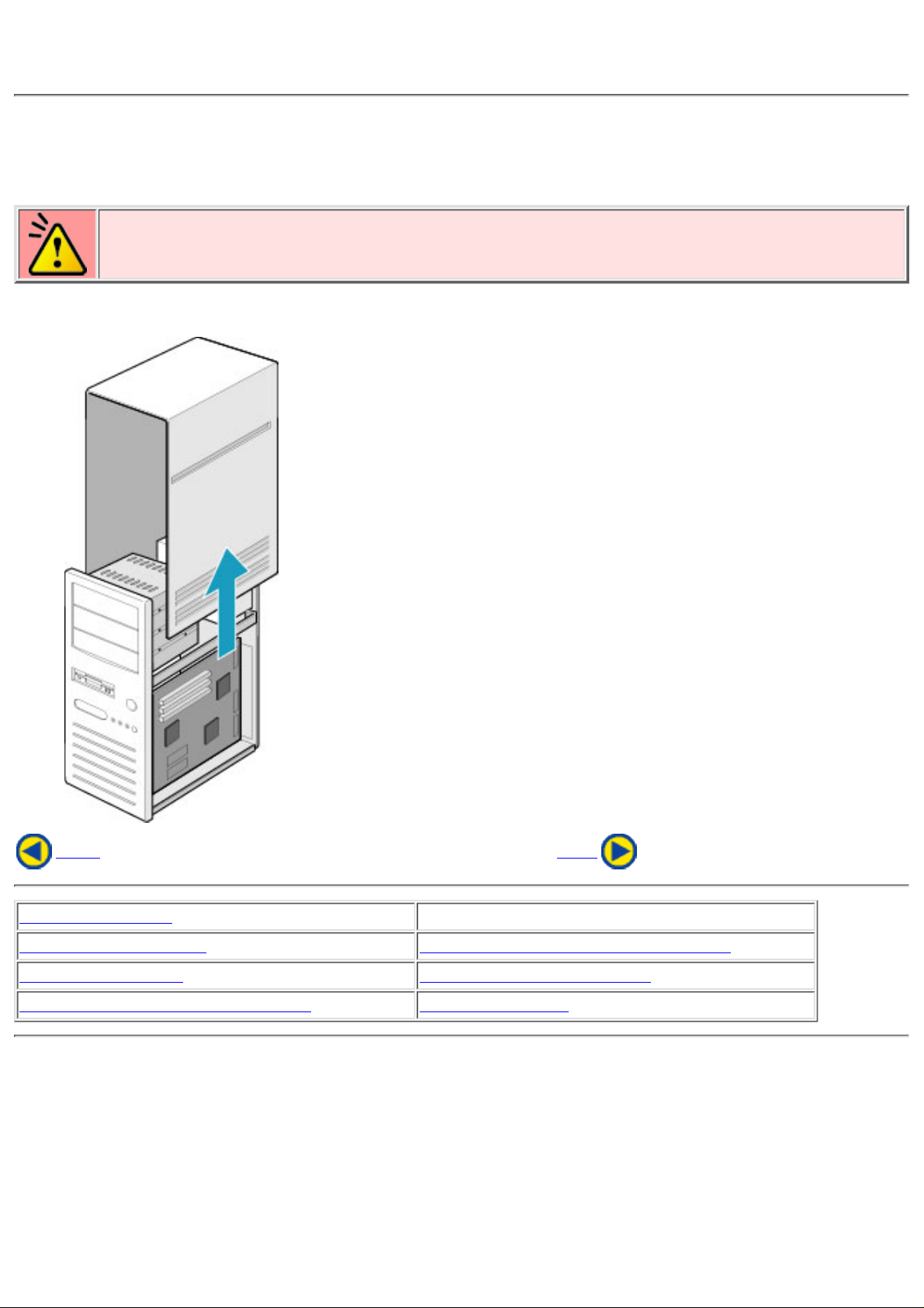
2. Removing the Computer Cover
Make sure all peripheral devices of the computer and the computer itself are turned off, and then
remove the cover.
Refer to the manual for the computer for details about removing the cover.
Caution
There may be sharp edges inside the computer take care to avoid injury.
(Example: When newly installing the MP9200A drive into a PC.)
Back Next
1. Jumper Set Up
2. Removing the Computer Cover
3. Mounting the Drive 4. Connecting the Power Connector
5. PC Connections 6. Sound Card Connection
7. Replacing the Computer Cover 8. Device Drivers
Page 23
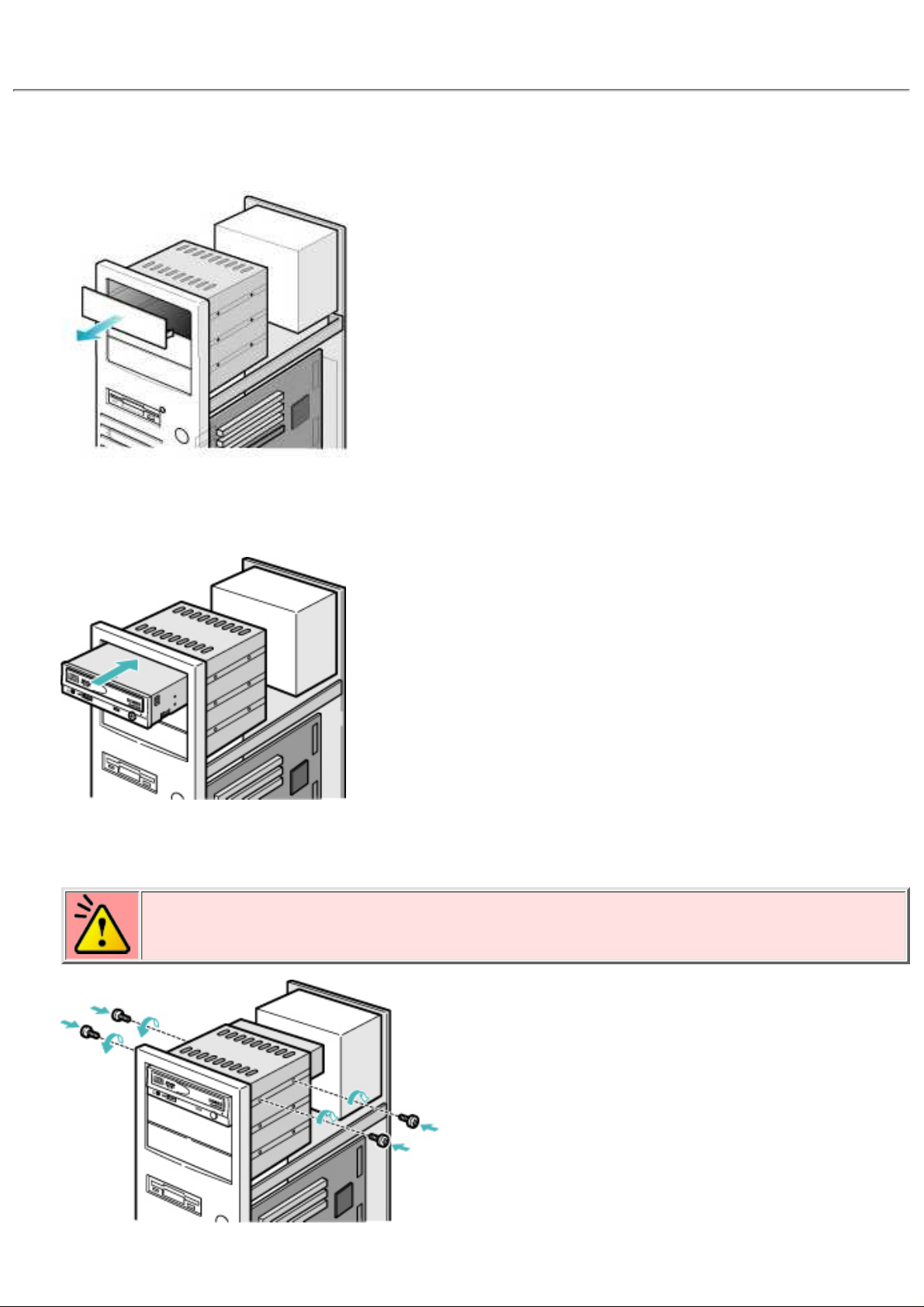
3. Mounting the Drive
Remove the 5 inch drive bay panel from the computer.
Refer to the manual for the computer for details.
1.
Insert the drive unit into the bay.
Do not apply excessive pressure to the cables inside the computer.
2.
Secure the drive with the screws provided.
If there is not enough space behind the drive, connect the E-IDE cables etc. before securing the drive.
Caution
Be aware that some computers do not require all of the four mounting screws for securing
the drive.
3.
Page 24

Back Next
1. Jumper Set Up 2. Removing the Computer Cover
3. Mounting the Drive
4. Connecting the Power Connector
5. PC Connections 6. Sound Card Connection
7. Replacing the Computer Cover 8. Device Drivers
Page 25
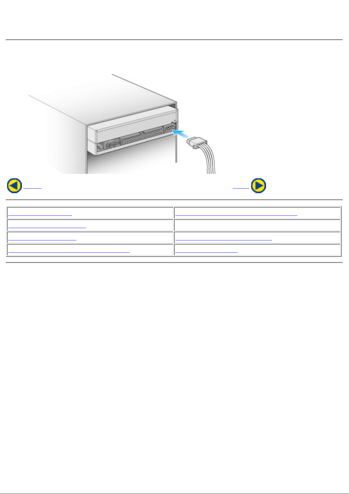
4. Connecting the Power Connector
Connect the power cable from the computer's power supply to the socket on the drive unit,
fitting the connector properly into the socket.
Back Next
1. Jumper Set Up 2. Removing the Computer Cover
3. Mounting the Drive
4. Connecting the Power Connector
5. PC Connections 6. Sound Card Connection
7. Replacing the Computer Cover 8. Device Drivers
Page 26
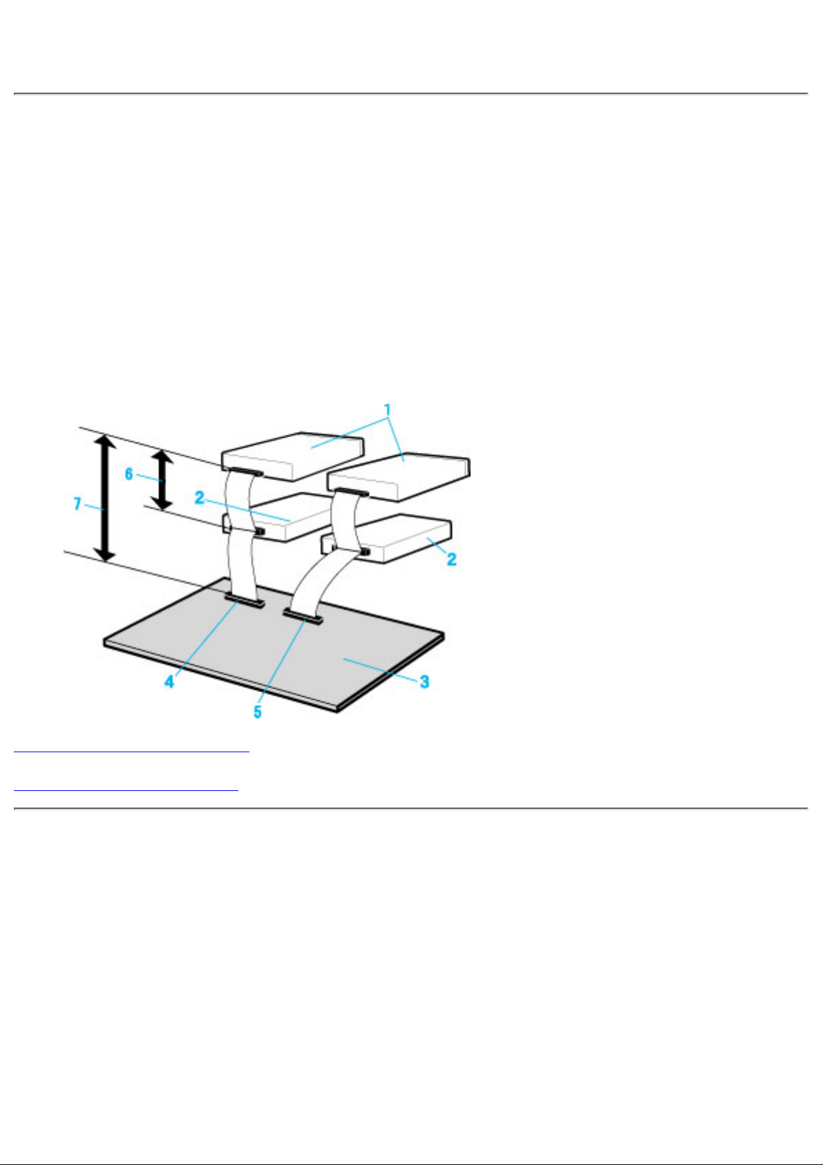
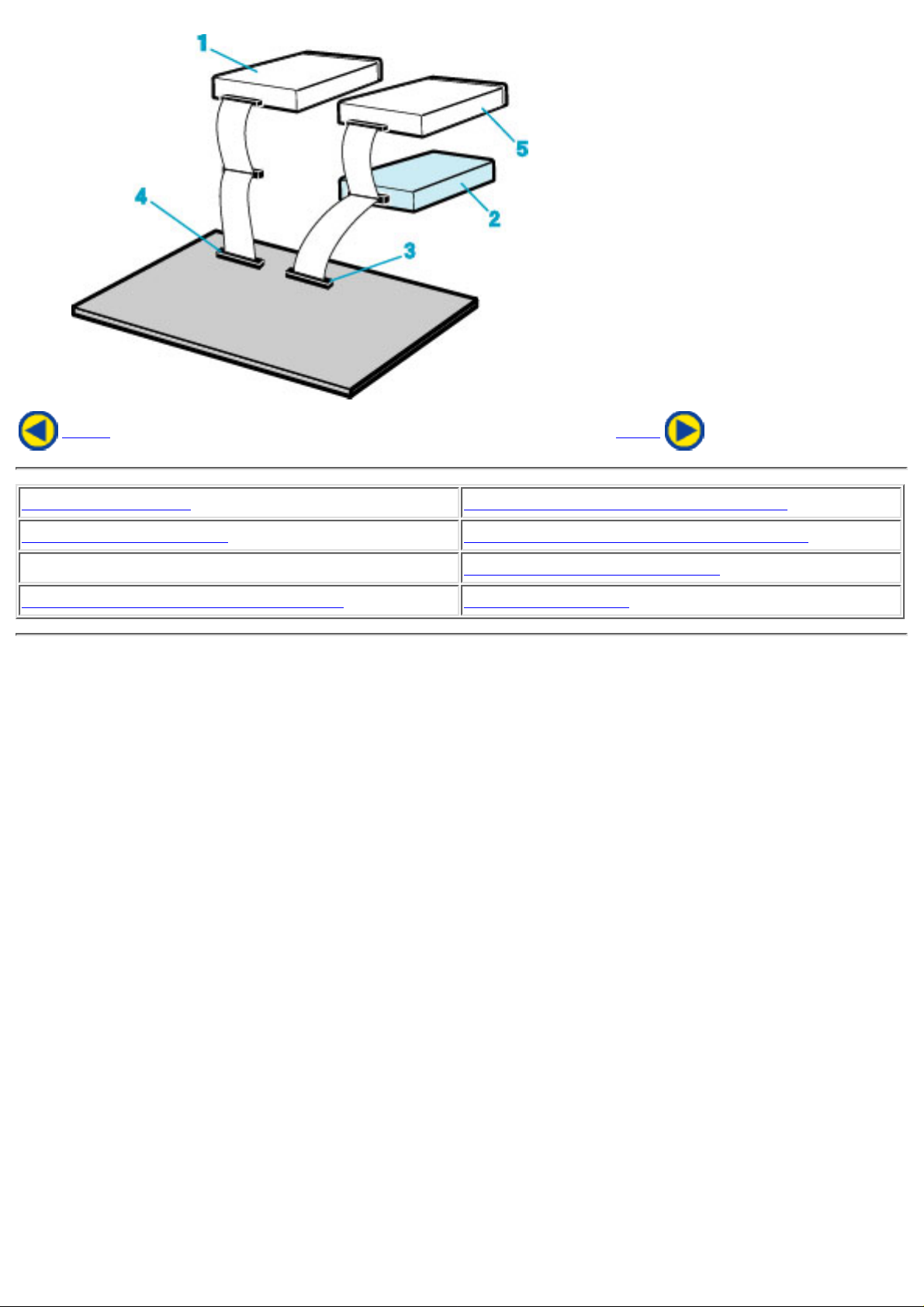
5. PC Connections
The drive connects to the motherboard of the host computer using an IDE interface cable.
Both Primary and Secondary connectors are usually provided on the motherboard, which
may be connected as follows:
Master1.
Slave2.
Motherboard3.
Primary4.
Secondary5.
less than 6 inches6.
less than 18 inches7.
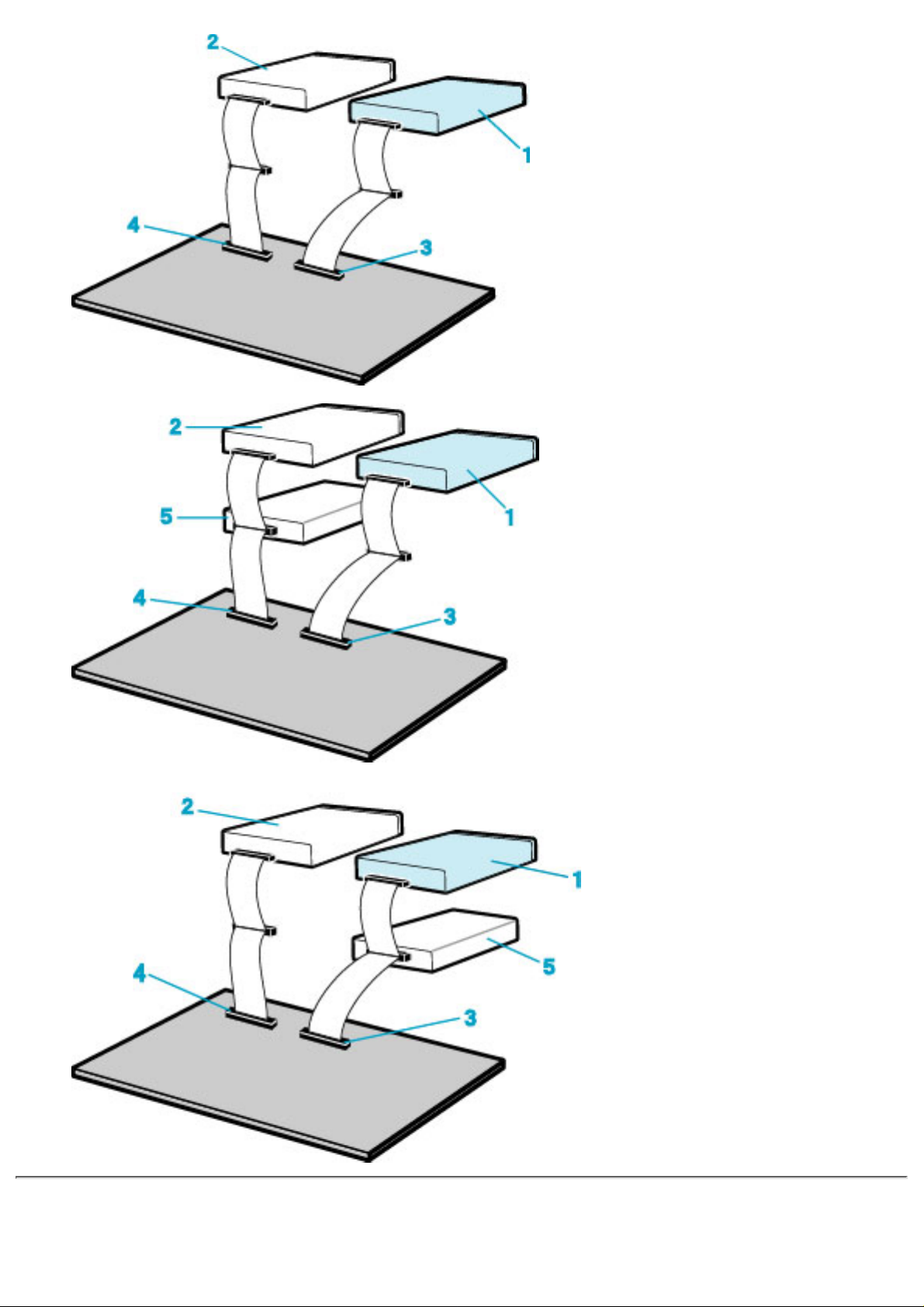
To Install as a Master Drive
To Install as a Slave Drive
To Install as a Master Drive
To install the drive as a Master, the jumper can be left as supplied from the factory.
Master drive (MP9200A)1.
Master drive (Booting hard disk)2.
Secondary connector3.
Primary connector4.
Slave drive (Other IDE drive)5.
Page 27
Page 28
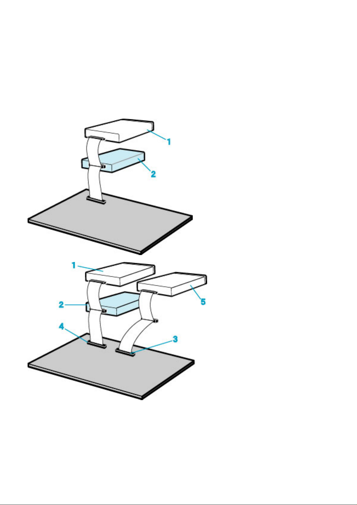
To Install as a Slave Drive
When connecting the drive as a slave drive, change the position of the slave setting jumper
pin on the rear of the system unit.
Master drive (Booting hard disk)1.
Slave drive (MP9200A)2.
Secondary connector3.
Primary connector4.
Master drive (Other IDE drive)5.
Page 29
Back Next
1. Jumper Set Up 2. Removing the Computer Cover
3. Mounting the Drive 4. Connecting the Power Connector
5. PC Connections
6. Sound Card Connection
7. Replacing the Computer Cover 8. Device Drivers
Page 30
6. Sound Card Connection
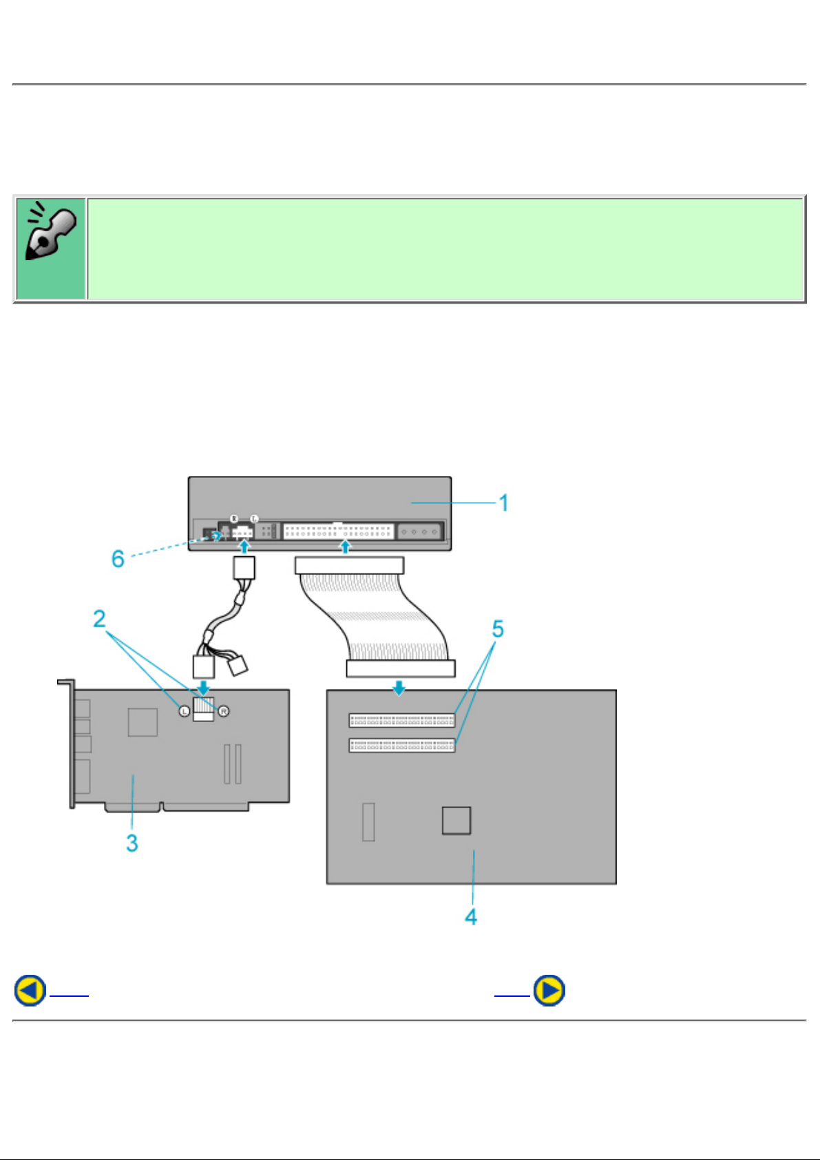
If the computer has a sound card, the drive can be connected to the sound card with an audio cable.
Make sure the connections are oriented so that L corresponds to L and R to R.
Refer to the manual for the sound card for detailed information regarding connection.
Audio digital output
The drive supports S/PDIF(IEC958) for digital audio output. As long as the sound board
comes with S/PDIF input, it can be connected externally to the D/A converter. The drive can
be used as a CD transporter for playing CDs at the desired sound quality level.
*
1. MP9200A
2. When L,R
3. Sound Card
4. Motherboard
5. Primary or secondary
6. Digital audio output terminal
* Please purchase a digital-audio-capable sound board and a cable at additional cost.
Back Next
Page 31

1. Jumper Set Up 2. Removing the Computer Cover
3. Mounting the Drive 4. Connecting the Power Connector
5. PC Connections
6. Sound Card Connection
7. Replacing the Computer Cover 8. Device Drivers
Page 32
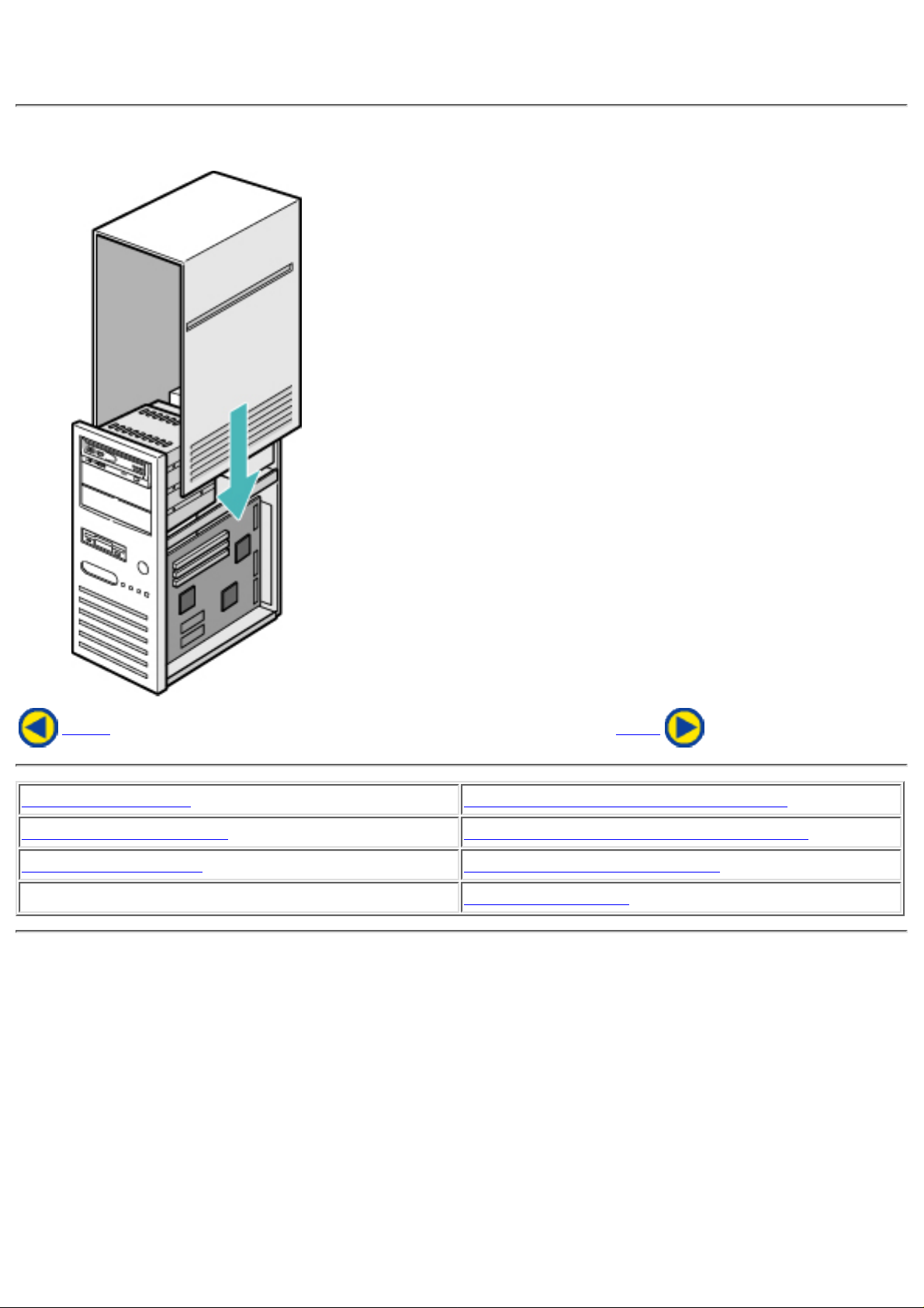
7. Replacing the Computer Cover
When the installation of the drive unit is complete, replace the computer cover.
Back Next
1. Jumper Set Up 2. Removing the Computer Cover
3. Mounting the Drive 4. Connecting the Power Connector
5. PC Connections 6. Sound Card Connection
7. Replacing the Computer Cover
8. Device Drivers
Page 33

8. Device Drivers
When using Windows 98/95, Window NT Workstation Ver. 4.0, Windows 2000 (Professional)
the installation of any special device drivers are not required.
In order to ensure normal drive operation or if the drive is not recognized by your computer,
please check the following:
In order to ensure normal drive operation
If the drive is not recognized by your computer
In order to ensure normal drive operation
For Windows 98/95 Users
The drive is displayed in [control panels] - [system] - [device manager] - [CD-ROM]●
32-bit is displayed in [control panels] - [system] - [performance]●
For Windows NT Workstation Ver.4.0 Users
The drive is displayed on the IDE controller in [control panels] - [SCSI adapter]
-[devices]
●
For Windows 2000 (Professional) Users
The drive is displayed in [control panels] - [system] - [hardware] - [device manager]●
If the drive is not recognized by your computer
For Windows 98/95 Users
If a [!] indicator is displayed on the IDE controller in [control panels] - [system] -[devices
manager]-[harddisk controler], you will need to contact your PC manufacturer or the
motherboard manufac-turer and get the appropriate IDE controller driver.
●
For Windows NT Workstation Ver.4.0 Users
If a [!] indicator is displayed on the IDE controller in [control panels] - [SCSI adapter]
-[devices] , you will need to contact your PC manufacturer or the motherboard
manufacturer and get the appropriate E-IDE controller driver.
●
For Windows 2000 (Professional) Users
If a [!] indicator is displayed on the IDE controller in [control panels] - [system] [hardware] - [device manager] , you will need to contact your PC manufacturer or the
motherboard manufacturer and get the appropriate E-IDE controller driver.
●
Page 34

Back
1. Jumper Set Up 2. Removing the Computer Cover
3. Mounting the Drive 4. Connecting the Power Connector
5. PC Connections 6. Sound Card Connection
7. Replacing the Computer Cover
8. Device Drivers
Page 35

Caution
When using CD-ROM discs, DVD-ROM discs, CD-R discs or CD-RW discs, do not attach
any stickers or labels to the discs. Using discs with labels attached not only causes read
and write errors, but data on the disc may be lost due to damage to the disc itself.
Load the disc●
Disc ejection●
Emergency Eject●
Using the Drive in a Vertical Position●
Page 36
Drive : MP9200A
Type
Internal type
Interface
Enhanced-IDE (ATAPI)
Data buffer memory
2MB
Data transfer speed
33MB/sec. (Max.) (Ultra DMA mode2)
CD-RW/High Speed
CD-RW Write/Read speed
(Ave.)
Read Speed
4X: 600KB/sec.
8X: 1200KB/sec.
20X:
3000KB/sec.
*1
32X:
4.8MB/sec.
*1
40X:
6.0MB/sec.
*1
Write Speed
CD-R:
4X: 600KB/sec.
8X: 1200KB/sec.
12X: 1800KB/sec.
16X: 2.4MB/sec.
20X: 3.0MB/sec.
CD-RW:
4X: 600KB/sec.
10X: 1.5MB/sec.
DVD Read Speed:
12X: 16.5MB/sec.(MAX)
Caution
When the 20X write speed is specified, data is written at 16X from the
innermost track to about the 70 MB position, and at 20X from positions
exceeding 70 MB up to the outermost track.
*:When using a disc capable of the 20X speed.
*:The lead-in area is written at the 12X speed.
Average access time
100msec.
Initial processing time
CD-ROM 14sec. or less
CD-R/RW (also High Speed CD-RW) 19sec. or less
Mounting direction
horizontal/vertical (eject button upper)
Writing Mode
Track At Once, Disc At Once, Multi-session, Packet Write, Session At Once.
Page 37
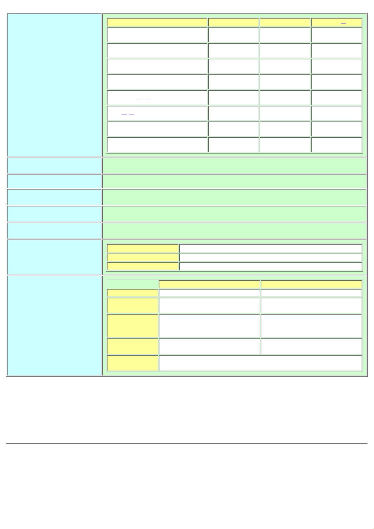
Compatible formats
Format Write Read
Play
*2
CD-DA
* * *
CD-ROM
* *
CD-Extra
* * *
CD-ROM XA
* *
Photo CD*3
*4
* *
CD-i*3
*4
* *
Video-CD
* *
CD-Text
* *
Loading system
Tray type (automatic loading/eject)
Power DC5V, DC12V
Power consumption
14w
Weight
Less than 1.2 Kg.
Dimensions
146 X 198 X 41.3mm
Reliability
Error Rate:
10
-12
bits or less
MTBF: 100,000hours or greater
MTTR: Within 30 minutes
Environmental Conditions
When operating When not operating
Temperature 5°C to 40°C (No air cooling) -30°C to 65°C
Humidity 5% to 90% R.H.
(No condensation)
5% to 95% R.H.
(No condensation)
Vibration 0.035mmpp (10 - 45Hz)
0.025mmpp (45 - 65Hz)
0.2 X 9.8 m/s
2
(65 - 150Hz)
1 X 9.8 m/s
2
(5 to 300Hz)
Shock
2 X 9.8 m/s
2
(3msec. half sine)
50 X 9.8 m/s2
(11msec. half sine)
Environmental
dust
Class 3 million or less (3 million particles of 0.5 micron dustper
cubic foot or less)
*1 Speed is automatically reduced if reading is unsuccessful.
*2 "Play" means playback. Also, "Read" means transferring data.
*3 CD-i and Photo-CD discs require special reader/player. Also, Photo-CD requires a
license from Kodak.
*4 Bundled software does not support these writing formats.
The drive's appearance and specifications may change without notice.
Page 38

* All references to the product in this document are to specifications in effect
when the product was released.
Copyright RICOH Co.Ltd.
All rights reserved.
 Loading...