

Page 1

RICOH M5
SERVICE MANUAL
Page 2

OPERATING
INSTRUCTIONS
Page 3

INTRODUCTION
May, 25, 1985
The Ricoh M5 is a desktop plain
carefully manufactured to exacting
formance.
a superior finish.
This manual contains detailed instructions on the opera-
tion and care of the M5.
from this copier, all
follow the instructions in this manual. Please
manual in the holder provided on the machine.
It consistently yields high contrast copies with
T
O get the maximum
operators should carefully
paper copier which is
standards of high per-
versatility
read and
keep this
MAJOR FEATURES
1
.
Copies everything from
1 l“) sized documents.
2
Easy-to-maintain cartridge design.
.
Black, blue, green and red color application.
3.
business cards to A4 (8-1/2” x
4
Lightweight design for easy transport.
.
“Clam-shell” design makes misfeeds easy to clear.
.
5
6
.
Simple and reliable operation.
7
Inner cassette makes the copier compact.
.
Page 4

CONTENTS
1. INSTALLATION . . . . . . . . . . . . . . . . . . . . . . . . . . . . . 1
1-1. Unpacking procedure . . . . . . . . . . . . . . . . . . . 1
1-2. Installation procedure . . . . . . . . . . . . . . . . . . . 2
1-3. Installation requirements . . . . . . . . . . . . . . . . 6
2. GUIDE TO COMPONENTS . . . . . . . . . . . . . 9
2-1. Overall machine layout . . . . . . . . . . . . . . . . . 9
2-2. operation panel . . . . . . . . . . . . . . . . . . . . . . ...10
2-3. Operator controls . . . . . . . . . . . . . . . . . . . . . ..ll
May, 25, 1985
3. COPYING
.
3-1
3-2
3-3
3-4
3-5
4
REPLENISHING SUPPLIES . . . . . . . . . . . . . . . . . . ...17
.
4-1. Loading paper...........*.. . . . . . . . . . . ...17
4-2. Adding toner . . . . . . . . . . . . . . . . . . . . . . . . ...19
.
5
6
.
7
Starting the copier . . . . . . . . . . . . . . . . . . . . . . 13
Normal copying . . . . . . . . . . . . . . . . . . . . . ...13
.
Manual feed copying . . . . . . . . . . . . . . . . . ...14
.
Two-sided copying . . . . . . . . . . . . . . . . . . ...15
.
Color copying . . . . . . . . . . . . . . . . . . . . . . . ...16
.
REPLACING THE MASTER UNIT . . . . . . . . . . . . . . .
TROUBLESHOOTING . . . . . . . . . . . . . . . . . . . . . . ...23
6-1. Clearing misdeeds . . . . . . . . . . . . . . . . . . . . ...23
6-2. Troubleshooting guide . . . . . . . . . . . . . . . . . . 24
6-3. Service codes . . . . . . . . . . . . . . . . . . . . . . . ...27
’IAINTENANCE . . . . . . . . . . . .
. . . . . . . . . . . . . . . . . . . . . . . . .. < . . . . ...13
0
. . . . . . . . . . . . . ...28
21
TRANSPORTING THE COPIER . . . . . . . . . . . . . . ...29
8
DO’S AND DON’TS . . . . . . . . . . . . . . .
9
10
.
SPECIFICATIONS . . . . . . . . . . . . . . . . . . . . . . . . . ...30
. . . . . . . . ...29
Page 5
1. INSTALLATION
May, 25, 1985
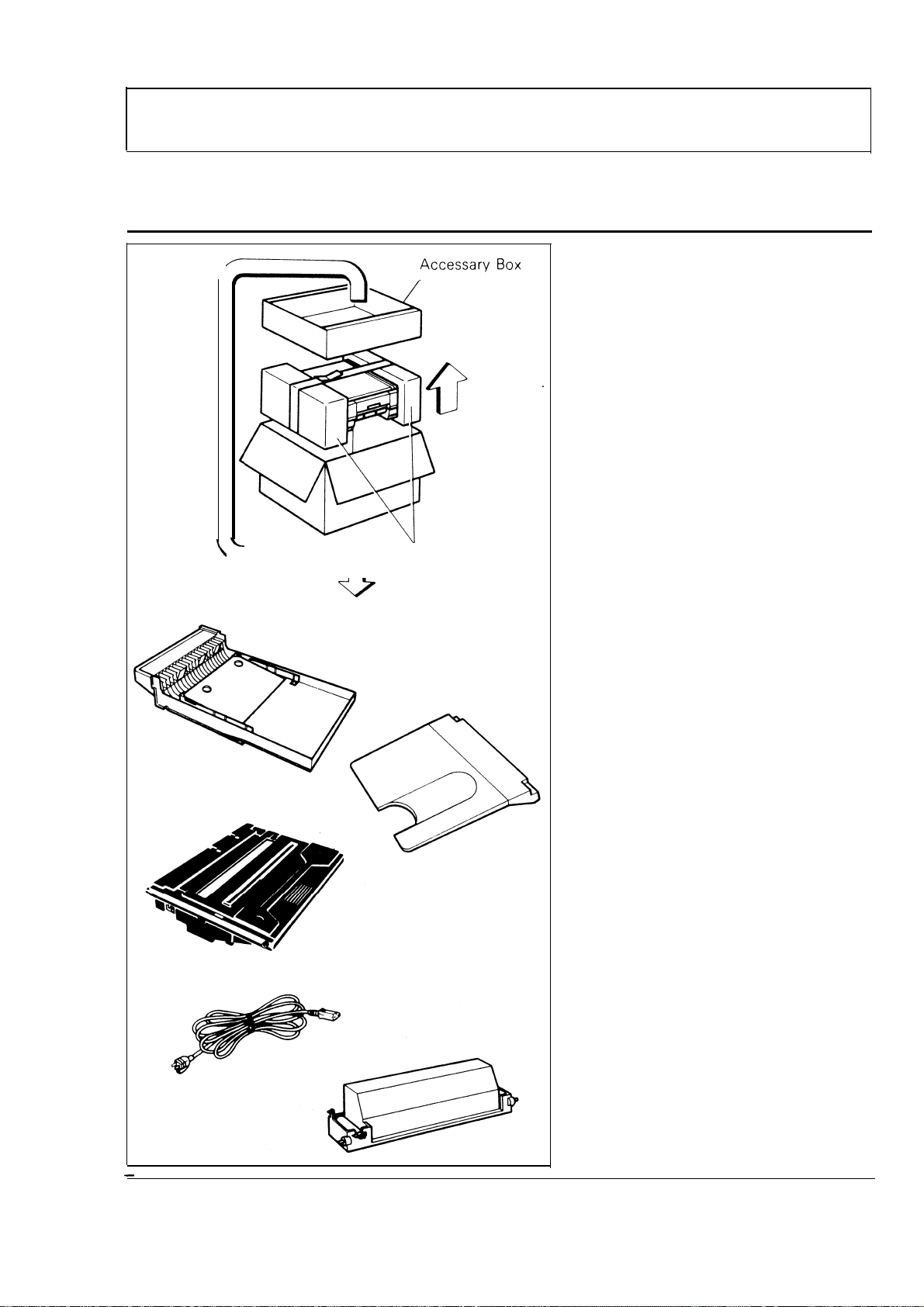
1-1.
UNPACKING PROCEDURE
1.
Take out the accessary box
and the machir
2
.
Remove the
blocks.
3,
Open the viny
out the machine.
4.
Check the quantity of the
accessories using the follow-
ing list.
1)
Cassette
e.
two
bag and take
cushion
1
pc
2)
Copy Tray
3)
Master Unit
(115V and 220V machines
only)
Note: Keep the master unit in
the box until installing it
in the copier.
4)
Power Supply Cord
Toner
5)
(115V and 220V machines
only)
1 cartridqe (Black)
1
pc
1 pc
1 pc
.
–1-
Page 6
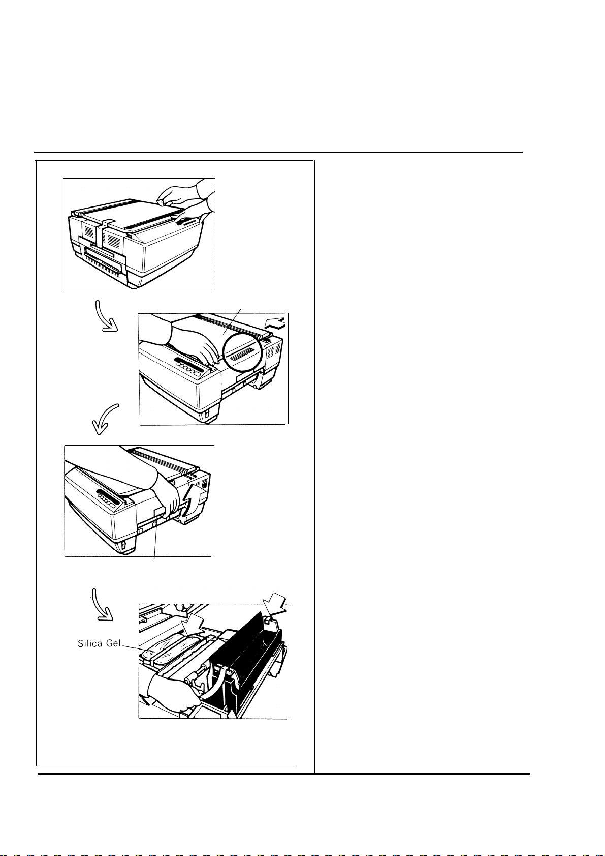
1-2. INSTALLATION PROCEDURE
Slider
May, 25, 1985
1
Remove the two strips of tape.
.
Z. Move the slider to the left until
the right edge of the copier is
exposed.
Release Latch
3. Squeeze the release latch and
open the top unit.
4. Remove the three strips of
tape and the silica gel.
—
Turn to the next page.
2–
Page 7

Master Release Lever
May, 25, 1985
5. Lower the master release lever.
6. Remove the three wedges
from the master unit.
Note: Do not touch the master
(purple material) and
avoid’ exposing
it to
light.
7. Insert the master unit into the
copier until it stops.
8. Peel the polyester cover off of
the master.
Page 8
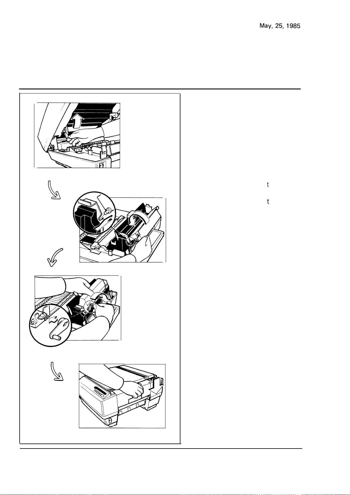
Return the master release lever
9
.
to its original position.
10
.
Shake a cartridge of
11
.
Set the pins of
cartridge into the slots on the
development unit. Then, turn
the
clockwise.
cartridge counter-
oner well.
he toner
Install the cartridge crank on
12
.
the shaft. Then, turn the
cartridge crank clockwise to
strip off the cartridge seal.
Remove the cartridge crank.
Note:
13
.
Lower the top unit.
At installation, it is recommended to load
two cartridges of toner.
Turn to the next page.
—
—
4
Page 9
May, 25, 1985
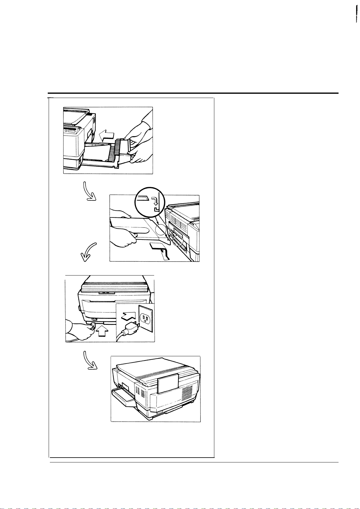
14. Load paper in the cassette as
shown on page 17, and insert
the loaded cassette until it
stops.
15. Install the copy tray on the left
side of the machine.
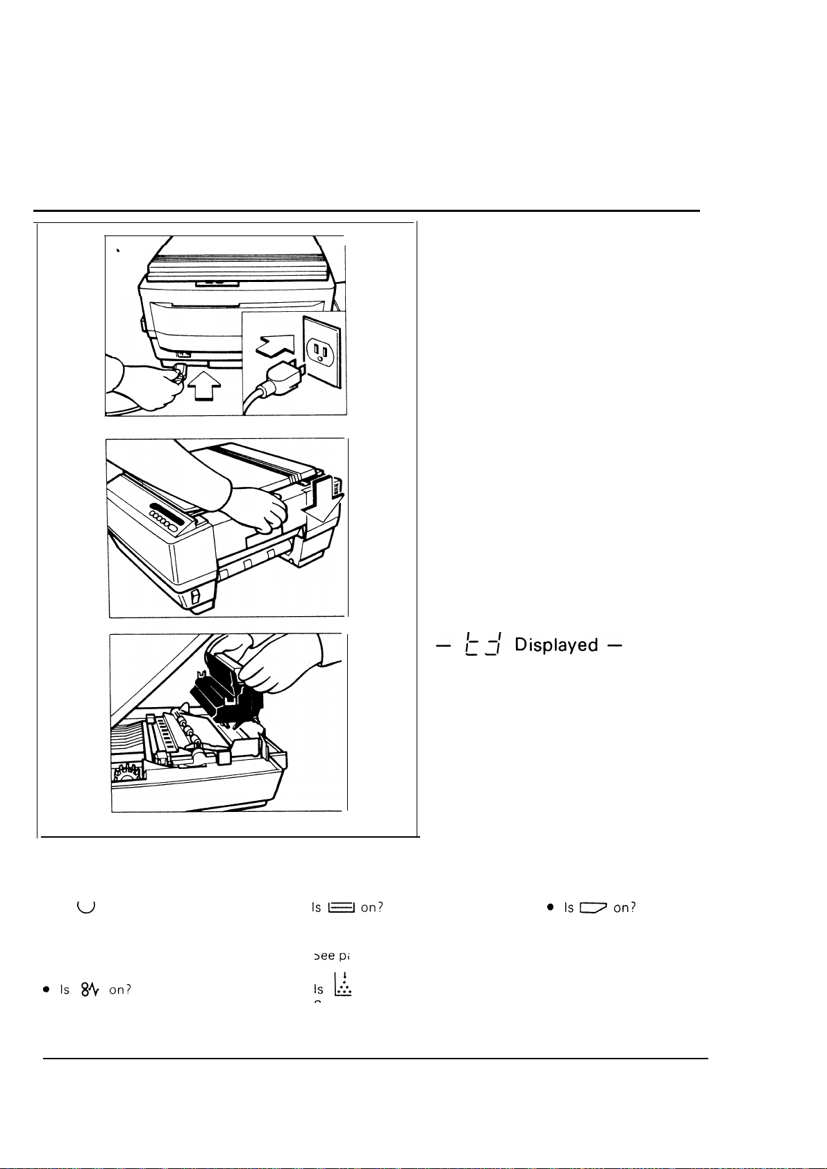
16. Connect the power
supply
cord.
17. When not using this
tion booklet, keep it
holder on the back
instruc-
in the
of the
copier.
This completes machine installation.
–5–
Page 10
May, 25, 1985
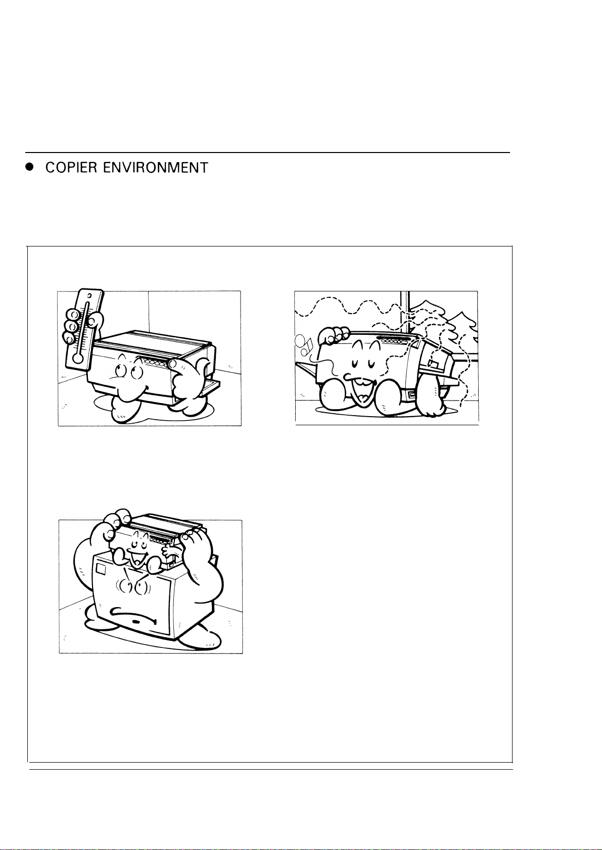
1-3. INSTALLATION REQUIREMENTS
The installation Iocatlon should be carefully chosen because environmental condi-
1l-ons greatly affect the performance of a copier
Optimum environmental conditions:
. Temperature . . . . . . . . 10–30° C
(50-86° F)
. Humidity . . . . . . . . .
. On a strong and level base (a
sturdy desk, etc. )
. The copier must be level within
5 mm (1 3/64”) both front to rear
and left to right
15–90% RH
. Well-ventilated and wide room
Minimum ventilation: air turnover
3 times/hour
—
Turn to the next page.
—
6
Page 11

Environments to avoid:
May, 25, 1985
● Locations exposed to direct sun-
light or strong light (more than
1,500
Iux)
● Dusty areas ‘
● Areas higher than 2,000 m
(6,500 ft) above sea level
● Areas where the copier may be
subjected to frequent strong
vibration
● Locations directly exposed to the cool air from an aircondi -
tioner or to reflected heat from a space heater
(Sudden temperature changes from low to high or vice versa may cause condensation within the copier. )
—
–7
Page 12
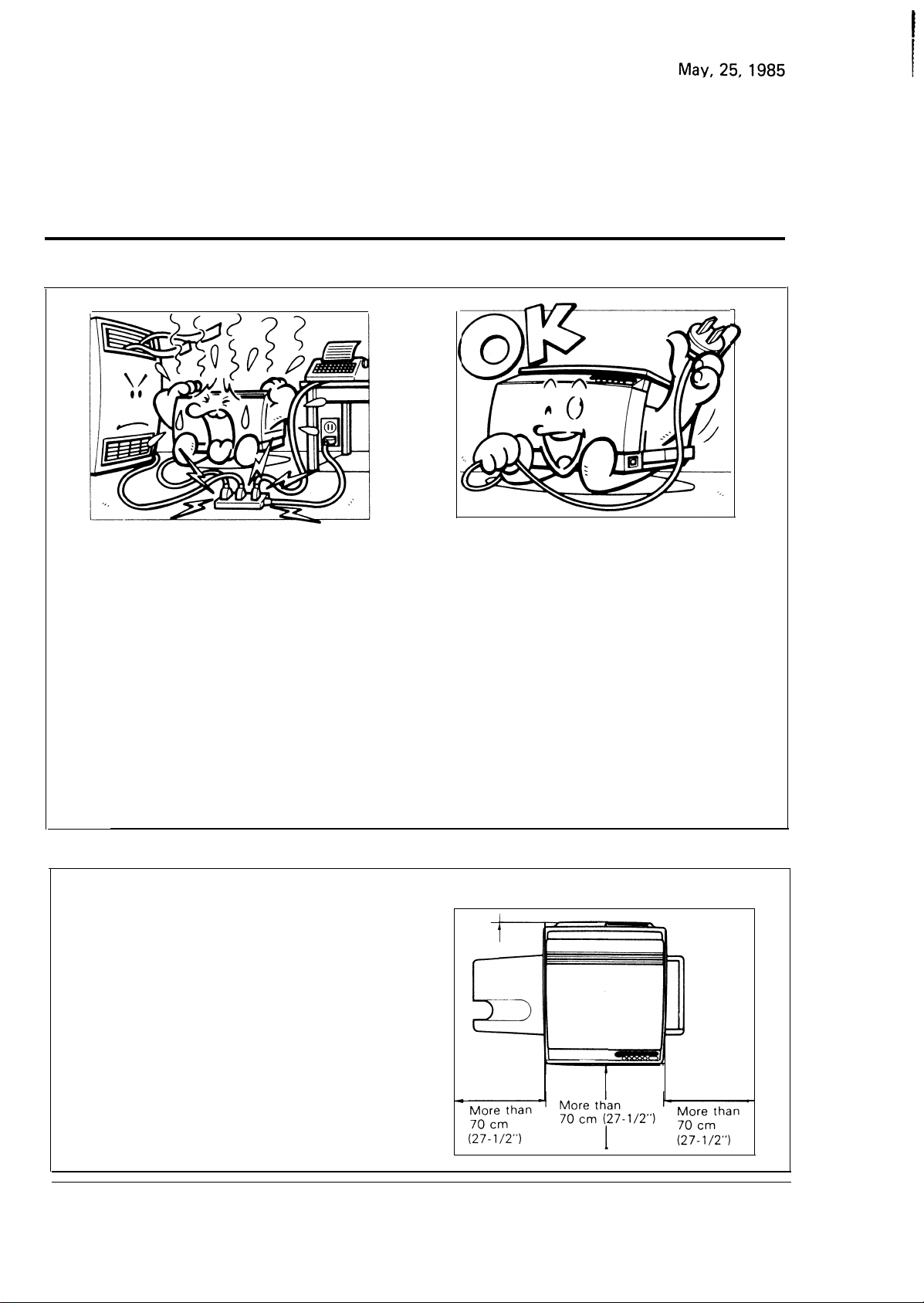
● POWER CONNECTION
●
Connect the power cord to a
power source as shown below
a) 115 V/60Hz : More than 12A
b) 220 V/50Hz : More than 6A
c) 240 V/50Hz : More than 6A
●
Voltage must not fluctuate more
than 10%.
●
Avoid multiwiring.
●
If an extension cord must be used, it must have a capacity of more than 300 V/30A
(300WZOA for 220/240V
machine) and be less than 5m (5.5 yds) long.
● ACCESS TO COPIER
Place the copier near a power source
●
providing clearance as shown.
.
●
Do not set anything on the
power cord.
●
Ground the copier properly to
prevent accidents.
Do not ground to a gas line.
●
Make sure the plug is firmly
inserted in the outlet.
More than 12 cm (4-3/4”)
—
—
8
Page 13
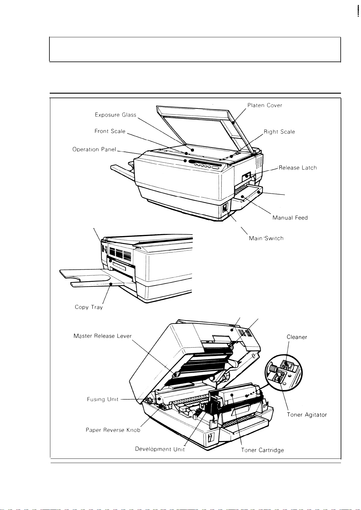
2. GUIDE TO COMPONENTS
May, 25, 1985
2-1.
Exit Cover
OVERALL MACHINE LAYOUT
—
Cassette
I
Guide
\
/
Top Unit
Master Unit
–9
—
Page 14
/
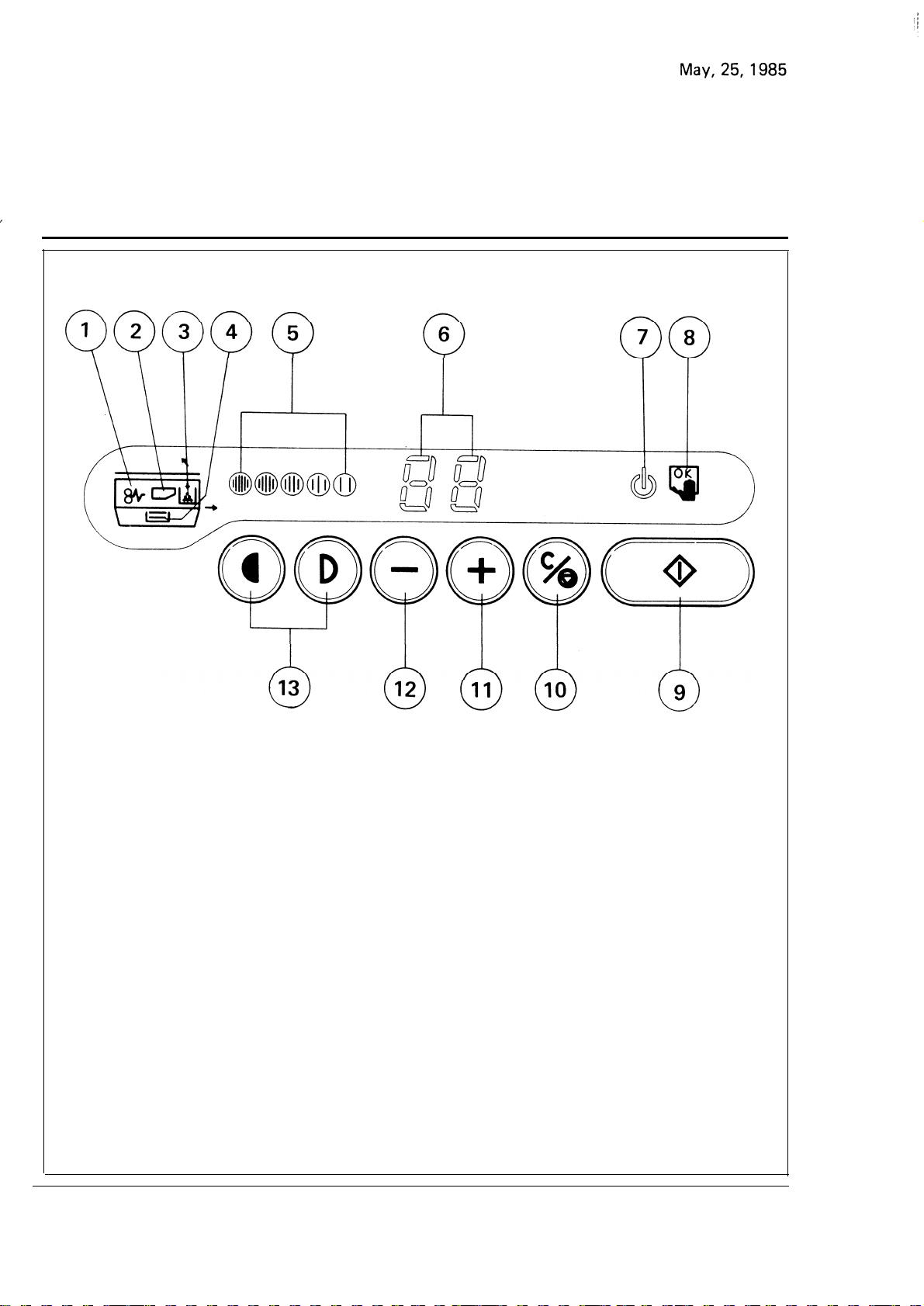
2-2. OPERATION PANEL
1.
Check Paper Path Indicator
2. Replace Master Unit
Indicator
3. Add Toner Indicator
4. Check Cassette Indicator
5.
Image Density Indicators
6. Copy Counter
7. Wait Indicator
—
10-
8. Manual Feed Indicator
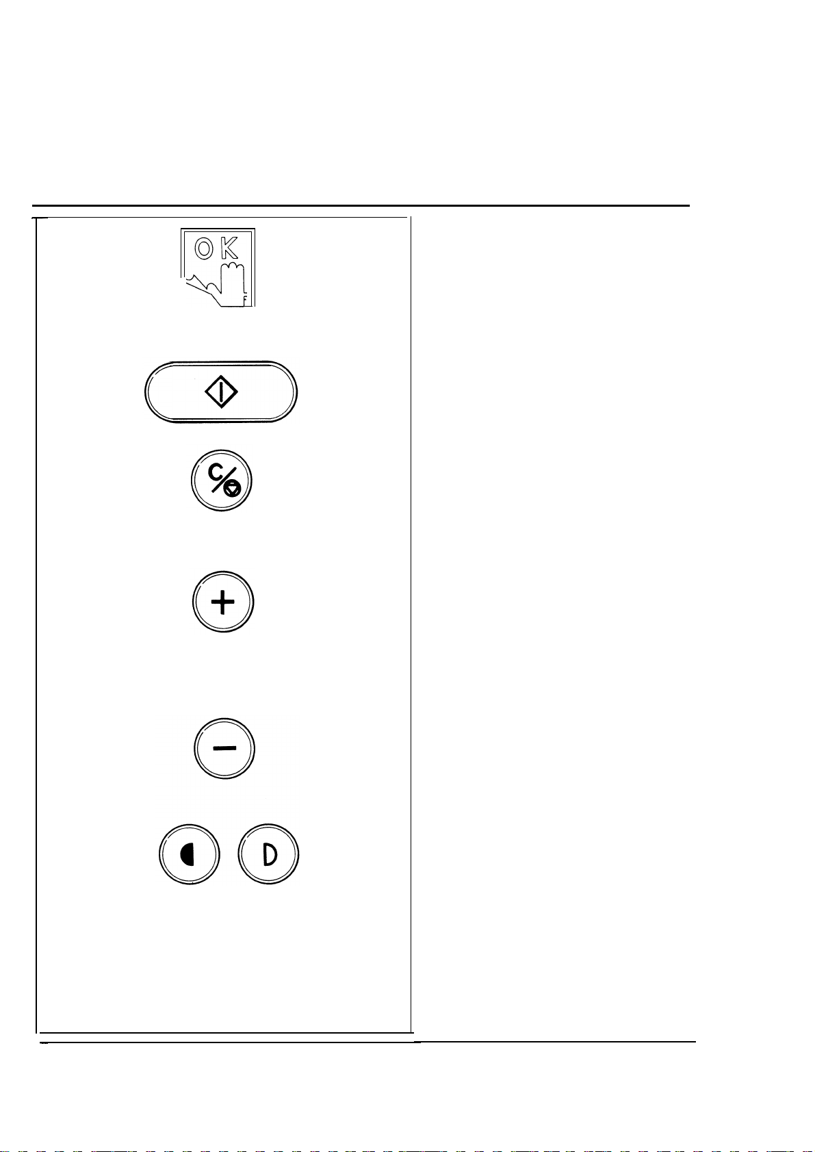
9. Start Key
10, Clear/Stop
11.
Increase Quantity Key
12. Decrease Quantity Key
13. Image Density Keys
Key
Page 15

2-3. OPERATOR CONTROLS
May, 25,1985
Check Paper Path Indicator
Lights when there is a paper
misfeed within the copier.
Replace Master Unit Indicator
Lights when it is time to change
the master unit.
Add Toner Indicator
Lights when it is time to change
the toner cartridge.
Check Cassette Indicator
Lights when either no paper is
in the cassette or the cassette is
not properly positioned.
Image Density Indicators
Shows the image density level
selected.
(Five levels from darkest to
lightest)
Copy Counter
Shows the number of copies
entered.
counter shows the number of
copies made.
While copying, this
(Count up type.)
–11–
Wait Indicator
Lights when the copier is warming up.
made when this indicator is on.
Copies cannot
be
Page 16
May, 25, 1985
●
Manual Feed Indicator
Lights when copy paper has
been inserted.
Blinks when the next sheet of
copy paper should be inserted.
●
Start Key
Press to start copy operation.
●
Clear/Stop Key
Press to cancel the copy number entered.
While copying,
press to stop copy operation.
●
Increase Quantity Key
Press to increase the copy entry
number. (The maximum number of copies that can be
entered is 20.)
● Decrease Quantity Key
Press to reduce the copy entry
number.
● Image Density Keys
Use these keys to
make copies
lighter or darker.
–12–
Page 17
3. COPYING
.
May, 25, 1985
3-1. STARTING THE COPIER
3-2. NORMAL COPYING
Turn on the main switch.
The Wait indicator ( ~ ) will turn
on, which means the copier
warming up. When this
turns off, copies can be m
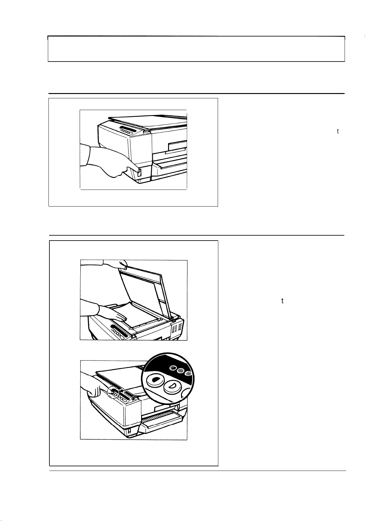
1
Raise the platen cover and
.
place the original face down
on the exposure glass.
indica or
ade.
,
is
Make sure the original is flush
with both
right scales
2. Adjust the image density to
match the type and quality of
the original by pressing the
Image Density keys.
he front and the
–
13
—
Page 18
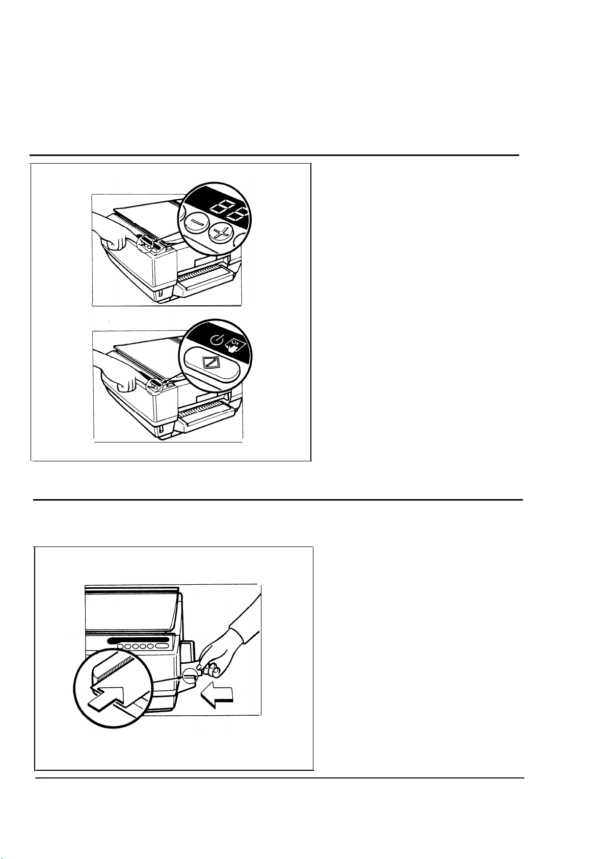
May, 25, 1985
Enter the number of copies
3
.
required by pressing
Increase Quantity key.
(Use the Decrease Quantity
key if you enter too many
copies.)
* Up to 20 copies can be
entered at one time.
* Press the Clear/Stop key to
cancel the entry.
4
Press the Start Key.
the
The number of copies made
will be continuously shown by
the copy counter.
(To stop the machine during a
multicopy
Clear/Stop key.)
3-3. MANUAL FEED COPYING
Use the manual feed entrance to copy onto paper of unusual
1
Insert
.
feed
above
Manual Feed indicator lights.
Note: Make sure that the
Position the original on the
2●
exposure glass and press the
Start key.
run,
size or weight.
paper into the manual
entrance
the cassette) until the
paper is flush against
the front edge of the
manual feed guide as
shown.
press
(the space
the
–14–
If making multiple copies,
3.
insert the next sheet of paper
into the entrance when the
Manual Feed indicator starts to
blink.
Page 19
3-4. TWO-SIDED COPYING
May, 25, 1985
1. Copy the first side in the normal manner. Then, insert the
copy into the manual feed
entrance
Feed indicator lights.
Important:
The copy must be inserted
facedown, and flush against
the front edge of the manual
feed guide.
until the Manual
2. Set the second original, and
press the Start key.
1
–15–
Page 20
May, 25, 1985
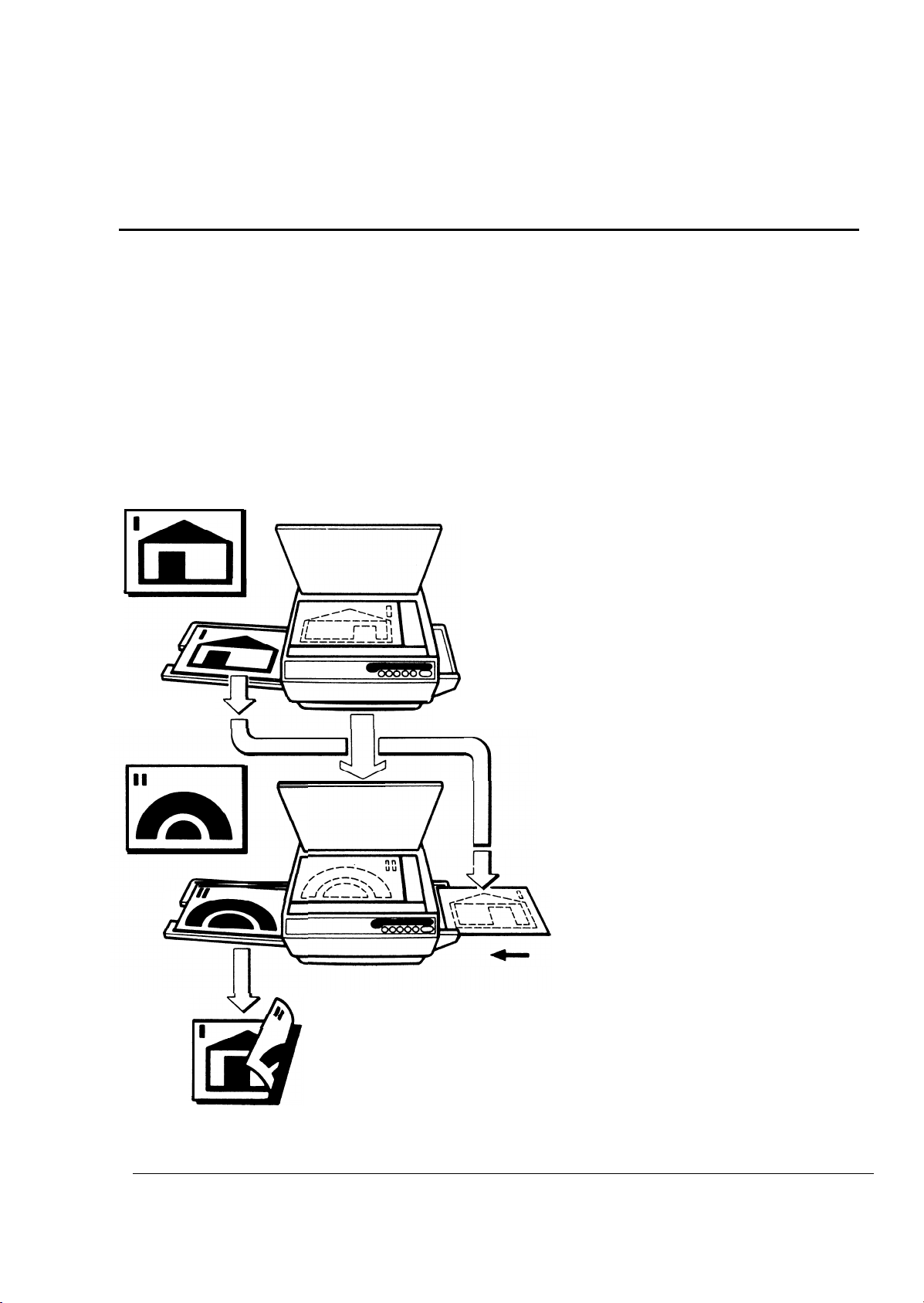
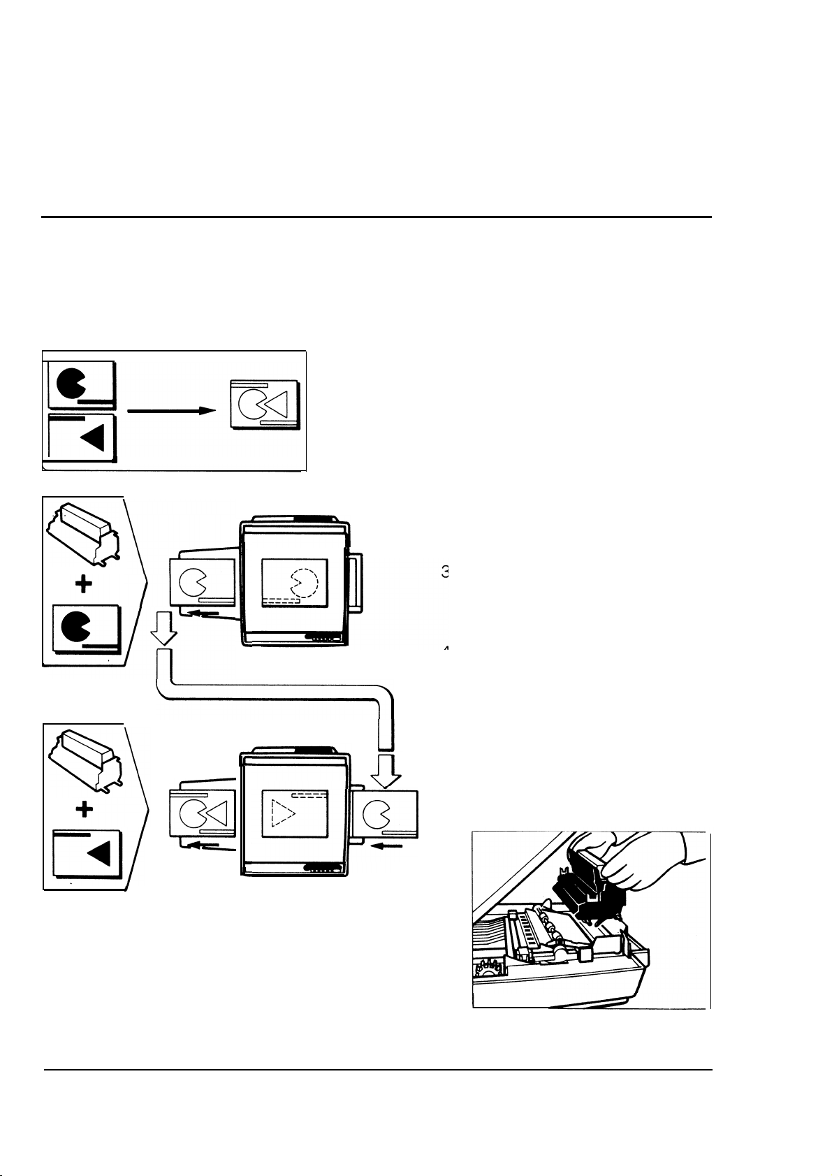
3-5. COLOR COPYING
Blue, green, and red development units and toner are available as options in addition
to standard black.
(You need a separate development unit for each color.)
Example: Making a green and blue
copy.
1
Install the green development
.
unit in the copier.
Place the black development
unit in the spare development
unit case.
2. Place the original to be copied
in green on the exposure glass,
and make the copy.
3. Insert the copy faceup into the
manual feed entrance.
4.
Exchange the green and blue
development units.
Place the original to be copied
.
5
in blue on the exposure glass
and press the Start key.
–16–
Page 21
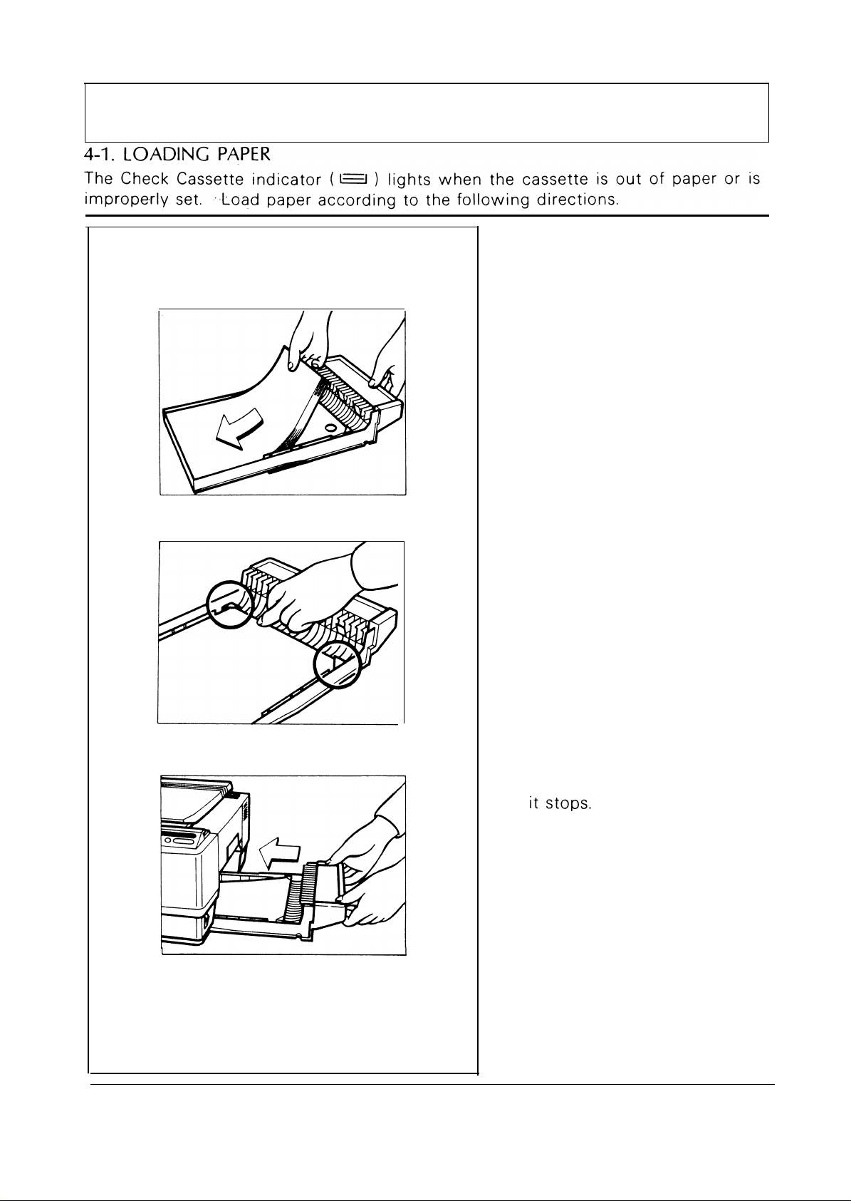
4. REPLENISHING SUPPLIES
1
.
Lift up and pull out the
cassette.
Load paper into the cassette
2
.
so that it is flush with the front
and side fences.
May, 25, 1985
Note: The
approximately
sheets.
Press down the corners of the
3
.
paper stack so that they catch
underneath the corner separators.
Insert the loaded cassette until
4,
cassette
holds
100
–17–
Page 22
May, 25, 1985
Paper Storage
Paper should always be stored properly, because poor paper condition will result in
.poor image reproduction, creased copies, and paper jams.
Generally, to avoid absorption
of moisture and curling:
. Avoid storing paper in humid
areas.
. NEVER store paper where it will
be exposed to heat.
● Store on a FLAT SURFACE.
● Use OLDER STOCK first.
● Do not lay any heavy objects on
paper.
. Keep open reams of paper in the
PACKAGE, and store as you
would unopened paper.
–18–
Page 23
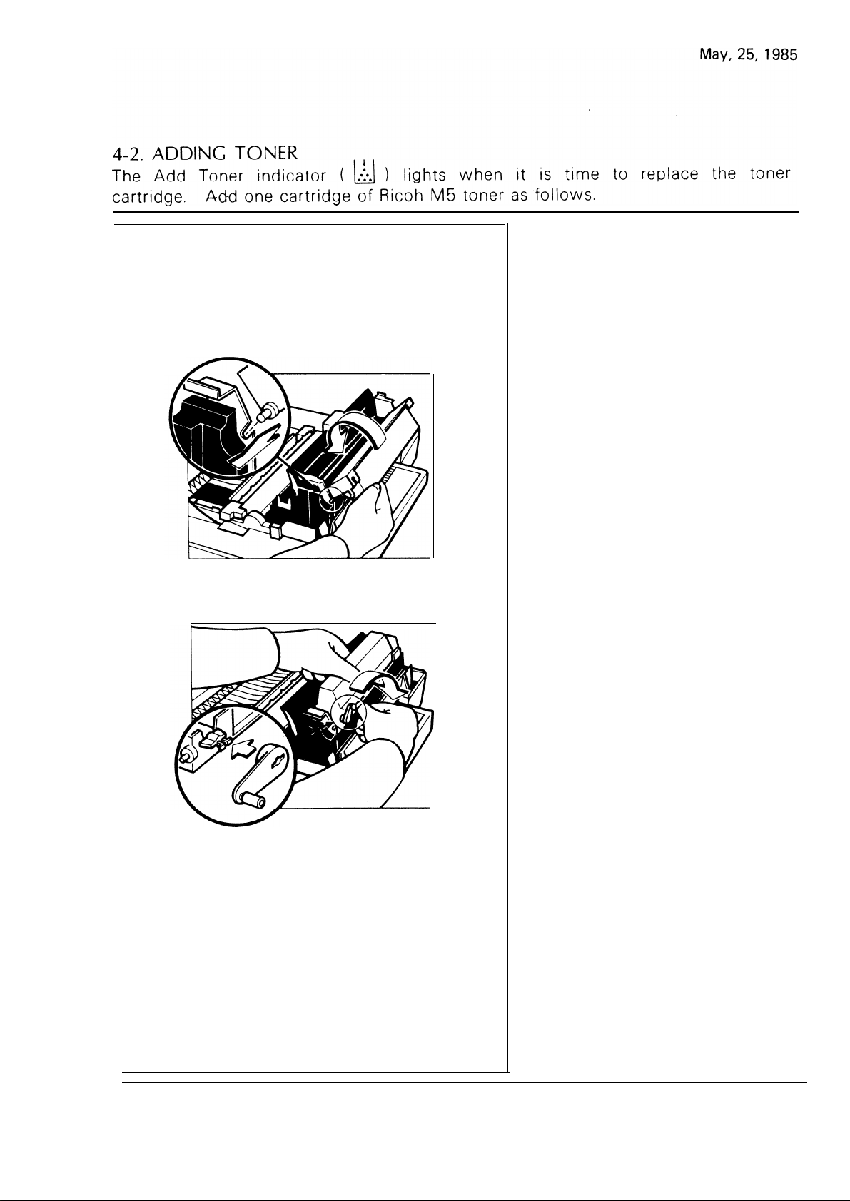
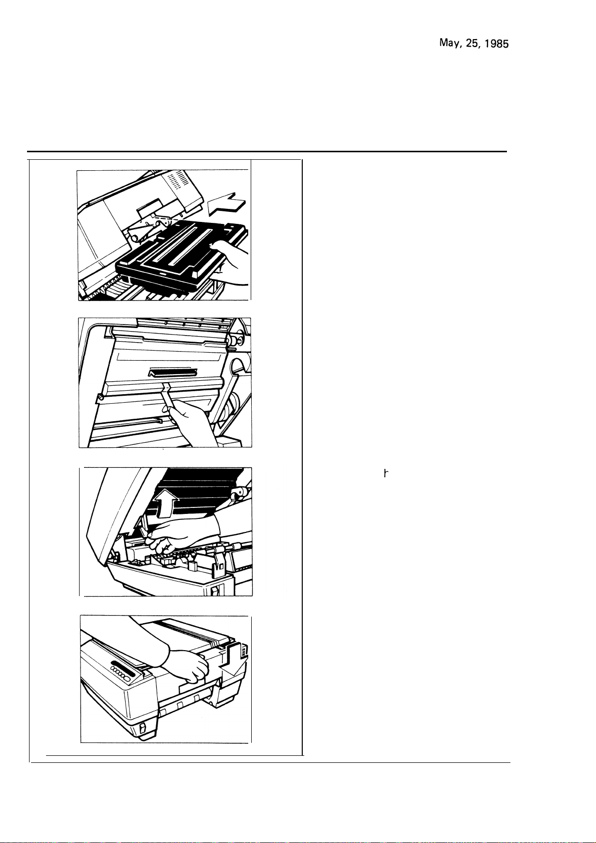
1.
Open the top unit.
2. Take out the toner cartidge.
3. Shake a new cartridge of toner
well
4. Set
the pins of the toner
cartridge into the slots on the
development unit. Then, turn
the
cartridge
counter-
clockwise.
5. Install the cartridge crank onto
the shaft and turn the cartridge
crank clockwise to strip off the
cartridge seal.
Then, remove the cartridge
crank and lower the top unit.
–
19
—
Page 24
Toner Storage
●
Store in a COOL, DARK place.
●
NEVER store toner where it will
be exposed to heat.
. Keep out of reach of children.
● Do not take internally.
●
Do not lay
anything heavy on
toner cartridges.
–
20
—
Page 25

May, 25, 1985
5.
REPLACING THE MASTER
1.
Squeeze the release latch and
open the top unit.
2
Lower the master release lever
.
and slide Out the used master
unit.
Dispose of the used unit using
the provided vinyl bag.
UNIT
Remove the three wedges
3
from the new master unit
Page 26
4. Insert the master unit into the
copier.
5. Peel off the polyester cover
that protects the master.
6. Returnth
e master release lever
to its original position.
7. Lower the top unit.
—
22
–
Page 27
6. TROUBLESHOOTING
May, 25, 1985
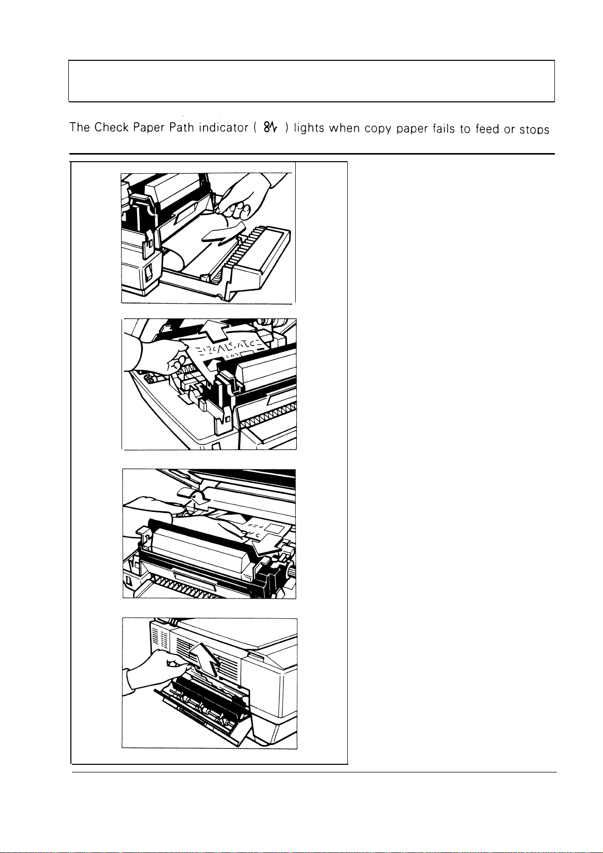
6-1.
before exiting the copier.
CLEARING MISFEEDS
1
Raise the top unit and remove
the jammed paper.
Note: Do not touch the master
(purple material).
If the paper is caught inside
2
the cassette,
cassette and remove the jammed paper.
3
If the paper is caught under
the development unit, remove
the jammed paper by pulling
on the leading edge.
This prevents the rollers from
getting dirty.
pull out the
Note: The copy image is not
fused at this time; be
careful not to get hands
or clothing dirty.
If the paper is caught in the
4
fusing unit, rotate the paper
reverse knob counterclockwise
to release it.
WARNING: The fusing unit is
hot. Avoid
touching it.
If the jammed paper can not be
5
removed by rotating the paper
reverse knob, close the top
unit and remove the copy
tray. Then,
cover and remove the jammed
paper.
open the exit
—
WARNING: Avoid touching
the INNER parts
of the machine.
23 –
Page 28
6-2. TROUBLESHOOTNG GUIDE
I
May, 25, 1985
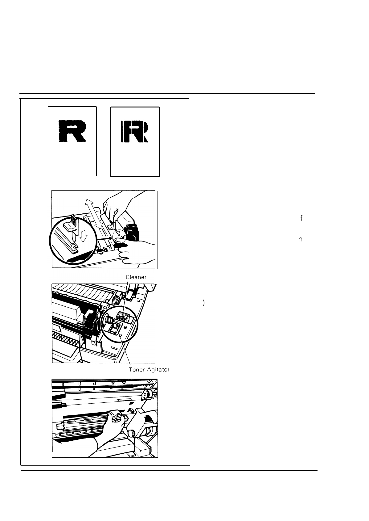
1. Faint Copies or White
Stripes on Copies
● Agitate the toner.
(1) Open the top unit and insert
the narrow tab of the toner
agitator into the slot in
development unit cover.
Slide the toner agitator
end to end several times.
the
from
(2) Keep the toner agitator or
I
holder inside the copier.
If the problem still exists after the
above, do the following:
●
Clean the fiber optics and corona wire.
(1
Open the top unit and take out
the master unit. Set it on a
clean sheet of paper.
Caution: Do not touch the
master (purple material), and avoid exposing it to light.
Insert the long pad of the
(2)
cleaner in the fiber optics slot,
and slide it end to end.
the
–24–
Turn to the next page.
Page 29

May, 25, 1985
(3) Clean the corona wire with the
short pad of the cleaner.
Gently rub the cleaner along
the wire.
(4) Keep the cleaner on the holder
inside the copier.
#
2. Copies have Dark stripes
or Heavy Background
First, try pressing the Lighter key to
adjust the image density.
If that does not help, do the following:
● Clean the exposure glass and
platen cover. (See page 28.)
● Clean the fiber optics.
(1) Open the top unit and take out
the master unit. Set it on a
clean sheet of paper.
(2) Insert the long pad of the
cleaner in the fiber optics slot,
and slide it from end to end.
Page 30
May, 25, 1985
”
3. Nothing Happens When
the Main switch is Turn-
ed On
– No Indicators On –
● IS the power cord plugged in?
Has
it been firmly inserted into
the copier?
. I
S the top unit
ed?
completely clos-
4. Copies cannot be Made
I
● Is
Wait for the copier to warm up.
See page 23.
on?
. Is the development unit in the
machine?
●
Check that the cassette is loaded
and properly set.
See page 17.
u
on?
●
See page 19.
See page 21.
● Is a service code
displayed?
See page 27.
– 26
—
Page 31

6-3. SERVICE CODES
May, 25, 1985
The copier’s microcomputer constantly monitors mechanical and
electrical functions. If a malfunc-
will turn on and a service code will
be displayed in the copy counter. If this happens, turn off the
main switch, wait a few seconds,
and then turn it on again.
Then, try operating the copier. If
the service code is displayed again,
call your dealer and tell him which
code is on.
(The service code tells the service
representative which tools and
parts to bring.)
–27–
Page 32

May, 25, 1985
7.
MAINTENANCE
To maintain a high copy quality, clean the exposure glass and platen cover regularly.
● Exposure Glass
Clean the
soft cloth
cleaner.
. Platen Cover
Clean the platen cover with a damp
cloth.
use a weak cleaning solution.
Note: If the waterproof paper
exposure glass with a
and commercial glass
If stains do not come off,
covering the platen cover
pad becomes badly stained,
you can obtain a new one
from your dealer.
–28–
Page 33

May, 25, 1985
8. TRANSPORTING THE COPIER
Before moving the copier from its
place of installation, remove the
copy tray and secure the slider
with strips of tape.
may be badly damaged if it is
moved when the slider is not pro-
perly secured.
safety, use the grips diagonally
opposite each other to handle the
copier.
Leave the master unit and development unit in the machine.
The copier
For MAXIMUM
\
r
9. DO’S AND DON’TS
Operating
Cautions
1.
While copying:
Do not turn off the main switch. Do not hold the slider.
Do not lift the platen cover.
2
.
Do not overload the cassette. (The MAXIMUM
3
.
Do not let the copy tray become overloaded (The MAXIMUM capacity is 20
4
.
Do not lay anything weighing more than 3 kg on the exposure glass.
.
Do not lay tools or other hard objects on the exposure glass.
5
6.
Keep corrosive liquids, such as acid, off the machine.
7.
Do not touch the copy paper if your fingers are wet or oily; fingerprints may appear
on the copy.
8.
Do not allow paper clips, staples, or other small metallic objects to fall inside the
machine.
9.
To avoid misfeeds, copy transparencies without a backing sheet. (Use recommended transparencies.)
Do not unplug the power cord.
I
.
capacity is 100 sheets.)
copies.)
10.
Do not touch the master (purple material) and avoid exposing
General Cautions
1,
Since some parts of the copier are supplied with high voltage,
switch is off before working on the copier.
2.
Do not modify or replace any parts other than the ones mentioned in this manual.
3.
When not using the copier for a long period, disconnect the power supply plug.
4,
Never store the master unit where it will be exposed to heat,
it to light.
make sure the main
–29–
Page 34

May, 25, 1985
10. SPECIFICATIONS
Configuration
Copy Process
Originals
Copy Size
Multiple Copying
Warm-Up Time
Automatic Reset
First Copy Time : 10 seconds
: Desktop (moving platen)
: Dry process (mono-component toner)
: Sheet/Book
: Maximum –
Minimum –
:
up to 20
: Approximately 15 seconds
: After 60 seconds
,
A4 (8-1/2”
Business card size (84 x 49
mm) (3-1/2” x 2“)
X 11“)
Copying Speed
Reproduction Ratio
Paper Feed
Toner Supply
Copy Paper
Copy Paper Weight
Power Source
Power Consumption
Dimensions
Weight
Note: To obtain the best copies, use Ricoh FT paper or a similar bond paper,
Ask your sales or service representative to recommend a brand of paper
that is suitable for use with the M5.
: 8 copies/minute
:1:1
: Single cassette (100 sheets) and Manual
Feed
: Cartridge (black, blue, red, and green)
: Bond paper/colored paper/mailing labels
OHP transparencies/translucent paper
mimeographic paper
: 52 to 157 g/m
: 1 15V/601+z/l 2A
220 V/50 Hz/6A, 240 V/50 Hz/6A
: 1.2 WA (1 15V), 1.4 WA (220/240V)
.
.
w
404 mm x 485 mm x 225 mm
(16“
X 19“ x 8-7/8”)
: Approximately
2
(14to 42 lb) (Manual Feed)
D
H
20 kg (44 lb)
Specifications are subject to change without notice.
–30–
Page 35

SERVICE MANUAL
Page 36

Contents
Specifications . . . . . . . . . . . . . . . .
. . . . . . . . . . . . . . . . . . . . ...* . . ...*
●
.-.’
Overall Machine Information
Functional Operation . . . . . . .
1
.
Copy processes . . . . . . . . . . .
2.
Mechanical Component Layout . . . . . . . . . . . . . . . . . . . . . . . . . . . . . . . . . . .
3.
Electrical Component Layout. . . . . . . . . . . . . . . . . . . . . . . . . . . . . . . . . . . . .
4.
Drive Layout . . . . . . . . . . . . . . . . . . . . . . . . . . . . . . . . . . . . . . . . . . . . . . . . . . .
.
5
Power Distribution
6.
- Ac Power Distribution . . . . . . . . . . . . . . . . . . . . . . . . . . . . . . . . . . . . . . . . .
- Dc Power Supply . .
-Power-On Reset . . .
Sectional Descriptions
Master Unit
1. Introduction . . . . . . . . .
2. Master Sensor . . . . . . . . . . . . . . . . . . . . . . . . . . . . . . . . . . . . . . . . . . . . . . . . .
3. Master Sensor Circuit . . . . . . . . . . . . . . . . . . . . . . . . . . . . . . . . . . . . . . . . . . .
..**.
●
1-1
2-1
2-2
2-4
2-6
2-8
2-10
2-11
2-12
3-1
3-2
3-3
Charge
I. Charge Corona . . . . . . . . . . . . . . . . . . . . . . . . . . . . . . . . . . . . . . . . . . . . . . . .
2. Charge Corona Circuit.. . . . . . . . . . . . . . . . . . . . . . . . . . . . . . . . . . . . . . . . .
3. Replacement of Parts
Charge Corona Wire . . . . . . . . . . . . . . . . . . . . . . . . . . . . . . . . . . . . . . . .
Charge Corona Power Pack.. . . . . . . . . . . . . . . . . . . . . . . . . . . . . . . . .
Exposure
Introduction . . . . . . . . . . . . . . . . . . . . . . . . . . . . . . . . . . . . . . . . . . . . . . . . . . .
1
.
2.
Slider Drive . . . . . . . . . . . . . . . . . . . . . . . . . . . . . . . . . . . . . . . . . . . . . . . . . . . .
3
.
Clutch Operation . . . . . . . . . . . . . . . . . . . . . . . . . . . . . . . . . . . . . . . . . . . . . . .
4
.
Slider Lock Mechanism . . . . . . . . . . . . . . . . . . . . . . . . . . . . . . . . . . . . . . . . .
5.
Slider Control Circuit . . . . . . . . . . . . . . . . . . . . . . . . . . . . . . . . . . . . . . . . . . .
6.
Exposure Lamp Control Circuit . . . . . . . . . . . . . . . . . . . . . . . . . . . . . . . . . . .
7
.
Lamp Heater Circuit . . . . . . . . . . . . . . . . . . . . . . . . . . . . . . . . . . . . . . . . . . . .
8
Replacement of Parts
.
Exposure Glass . . . . . . . . . . . . . . . . . . . . . . . . . . . . . . . . . . . . . . . . . . . . .
Fiber Optics . . . . . . . . . . . . . . . . . . . . . . . . . . . . . . . . . . . . . . . . . . . . . . .
Exposure Lamp . . . . . . . . . . . . . . . . . . . . . . . . . . . . . . . . . . . . . . . . . . . . .
Exposure Lamp Heater . . . . . . . . . . . . . . . . . . . . . . . . . . . . . . . . . . . . . .
Exposure Lamp Stabilizer.. . . . . . . . . . . . . . . . . . . . . . . . . . . . . . . . . . .
Slider Clutch . . . . . . . . . . . . . . . . . . . . . . . . . . . . . . . . . . . . . . . . . . . . . . .
Slider Solenoid . . . . . . . . . . . . . . . . . . . . . . . . . . . . . . . . . . . . . . . . . . . . .
Home Position Switch . . . . . . . . . . . . . . . . . . . . . . . . . . . . . . . . . . . . . . .
3-4
3-5
3-6
3-7
3-8
3-10
3-13
3-15
3-16
3-17
3-19
3-20
3-21
3-22
3-23
3-24
3-25
3-27
3-28
Page 37

9. Cleaning of Parts
Fiber Optics . . . . . . . . . . . . . . . . . . . . . . . . . . . . . . . . . . . . . . . . . . . . ...3-29
10. Lubrication of Parts
Fiber Optics Holders . . . . . . . . . . . . . . . . . . . . . . . . . . . . . . . . . . . . . ...3-30
Development
Black Development
1 .
2.
Color Development
Bias Application . . .
.
3
4
Drive Mechanism . .
.
Toner End Mechanism . . . . . . . . . . . . . . . . . . . . . . . . . . . . . . . . . . . . . . . ...3-37
5.
Development Cover Mechanism . . . . . . . . . . . . . . . . . . . . . . . . . . . . . . . ...3-38
6.
Bias Circuit . . . . . . . . . . . . . . . . . . . . . . . . . . . . . . . . . . . . . . . . . . . . . . . . . . . . 3-39
7.
Toner End Sensor Circuit . . . . . . . . . . . . . . . . . . . . . . . . . . . . . . . . . . . . . ...3-40
8.
Replacement of Parts
9.
Toner Metering Blade . . . . . . . . . . . . . . . . . . . . . . . . . . . . . . . . . . . . ...3-41
Image Transfer and Separation
I. Image Transfer . . . . . . . . . . . . . . . . . . . . . . . . . . . . . . . . . . . . . . . . . . . . . ...3-42
2. paper Separation . . . . . . . . . . . . . . . . . . . . . . . . . . . . . . . . . . . . . . . . . . . . ...3-42
3. Transfer Corona Circuit. . . . . . . . . . . . . . . . . . . . . . . . . . . . . . . . . . . . . . ...3-43
4. Replacement of Parts
Transfer Corona Nylon Wire . . . . . . . . . . . . . . . . . . . . . . . . . . . . . . ...3-44
Transfer Corona Wire..... . . . . . . . . . . . . . . . . . . . . . . . . . . . . . . . ...3-45
Transfer/Bias PowerPack . . . . . . . . . . . . . . . . . . . . . . . . . . . . . . . . ...3-46
. . . . . . . . . . . . . . . . . . . . . . . . . . . . . . . . . . . . . . . . . . . . .
. . . . . . . . . . . . . . . . . . . . . . . . . . . . . . . . . . . . . . . . . . . . .
May, 25, 1985
3-31
3-33
3-35
3-36
Cleaning
l. introduction . . . . . . . . . . . . . . . . . . . . . . . . . . . . . . . . . . . . . . . . . . . . . . . . ...3-47
2. Toner Overflow Detection . . . . . . . . . . . . . . . . . . . . . . . . . . . . . . . . . . . . . ..3~48
3. Toner Overflow Sensor Circuit . . . . . . . . . . . . . . . . . . . . . . . . . . . . . . . . ...3-49
Quenching
l. introduction . . . . . . . . . . . . . . . . . . . . . . . . . . . . . . . . . . . . . . . . . . . . . . . . ...3-50
2. Quenching Lamp Circuit. . . . . . . . . . . . . . . . . . . . . . . . . . . . . . . . . . . . . . ...3-51
3. Replacement of Parts
Quenching Lamp . . . . . . . . . . . . . . . . . . . . . . . . . . . . . . . . . . . . . . . . ...3-52
Paper Feed and Registration
Introduction . . . . . . . . . . . . . . . . . . . . . . . . . . . . . . . . . . . . . . . . . . . . . . . . ...3-53
1
.
2.
Manual Paper Feed . . . . . . . . . . . . . . . . . . . . . . . . . . . . . . . . . . . . . . . . . . ...3-53
Paper Feed Mechanism . . . . . . . . . . . . . . . . . . . . . . . . . . . . . . . . . . . . . . ...3-54
3.
4
.
Registration . . . . . . . . . . . . . . . . . . . . . . . . . . . . . . . . . . . . . . . . . . . . . . . . ...3-55
.
Paper Feed Solenoid Circuits and Timing . . . . . . . . . . . . . . . . . . . . . . . ...3-57
5
Page 38

.
Replacement of Parts
6
Paper Feed Solenoid . . . . . . . . . . . . . . . . . . . . . . . . . . . . . . . . . . . . . . . .
Registration Solenoid . . . . . . . . . . . . . . . . . . . . . . . . . . . . . . . . . . . . . . .
Paper Feed Sensor . . . . . . . . . . . . . . . . . . . . . . . . . . . . . . . . . . . . . . . . . .
7
.
Adjustment of Parts
Leading Edge Registration . . . . . . . . . . . . . . . . . . . . . . . . . . . . . . . . . . .
8
,
Lubrication of Parts
Paper Feed Spring Clutch . . . . . . . . . . . . . . . . . . . . . . . . . . . . . . . . . . . .
May, 25,1985
3-58
3-59
3-60
3-61
Transport . . . . . . . . . . . . . . . . . . . . . . . . . . . . . . . . . . . . . . . . . . . . . . . . . . . . . . . . .
Image Fusing
1
.
Introduction . . . . . . . . . . . . . . . . . . . . . . . . . . . . . . . . . . . . . . . . . . . . . . . . . . .
2
.
Drive Mechanism . . . . . . . . . . . . . . . . . . . . . . . . . . . . . . . . . . . . . . . . . . . . . . .
3
.
Fusing Control . . . . . . . . . . . . . . . . . . . . . . . . . . . . . . . . . . . . . . . . . . . . . . . . .
4
.
Fusing Lamp Control Circuit. . . . . . . . . . . . . . . . . . . . . . . . . . . . . . . . . . . . .
5
.
Replacement of Parts
Fusing Lamp . . . . . . . . . . . . . . . . . . . . . . . . . . . . . . . . . . . . . . . . . . . . . . .
Hot Roller . . . . . . . . . . . . . . . . . . . . . . . . . . . . . . . . . . . . . . . . . . . . . . . . .
Pressure Roller . . . . . . . . . . . . . . . . . . . . . . . . . . . . . . . . . . . . . . . . . . . . .
Hot Roller Strippers . . . . . . . . . . . . . . . . . . . . . . . . . . . . . . . . . . . . . . . . .
Fusing Thermoswitch . . . . . . . . . . . . . . . . . . . . . . . . . . . . . . . . . . . . . . .
Other Mechanical and Electrical Components
1
.
Safety Switch . . . . . . . . . . . . . . . . . . . . . . . . . . . . . . . . . . . . . . . . . . . . . . . . .
2
.
Pulse Generator . . . . . . . . . . . . . . . . . . . . . . . . . . . . . . . . . . . . . . . . . . . . . . . .
3
.
Jam Sensing . . . . . . . . . . . . . . . . . . . . . . . . . . . . . . . . . . . . . . . . . . . . . . . . . .
4
.
Indicator Board . . . . . . . . . . . . . . . . . . . . . . . . . . . . . . . . . . . . . . . . . . . . . . .
5
.
Replacement of Parts
Exterior Parts . . . . . . . . . . . . . . . . . . . . . . . . . . . . . . . . . . . . . . . . . . . . . . .
Standing up Clamshell . . . . . . . . . . . . . . . . . . . . . . . . . . . . . . . . . . . . . .
Ozone Filter . . . . . . . . . . . . . . . . . . . . . . . . . . . . . . . . . . . . . . . . . . . . . . . .
Main Motor . . . . . . . . . . . . . . . . . . . . . . . . . . . . . . . . . . . . . . . . . . . . . . . .
Pulse Generator . . . . . . . . . . . . . . . . . . . . . . . . . . . . . . . . . . . . . . . . . . . .
Main Board . . . . . . . . . . . . . . . . . . . . . . . . . . . . . . . . . . . . . . . . . . . . . . . .
Dc Power Supply Board . . . . . . . . . . . . . . . . . . . . . . . . . . . . . . . . . . . . .
Mylar and Seals . . . . . . . . . . . . . . . . . . . . . . . . . . . . . . . . . . . . . . . . . . . .
3-63
3-64
3-65
3-66
3-68
3-70
3-71
3-72
3-73
3-74
3-75
3-76
3-77
3-78
3-79
3-80
3-81
3-82
3-83
3-84
3-85
3-86
Remarks . . . . . . . . . . . . . . . . . . . . . . . . . . . . . . . . . . . . . . . . . . . . . . . . . . .
4-1
Page 39

Service Tables
I. Maintenance Guidance . . . . . . . . . . . . . . . . . . . . . . . . . . . . . . . . . . . . . . . . . .
2. Maintenance Table . . . . . . . . . . . . . . . . . . . . . . . . . . . . . . . . . . . . . . . . . . . . .
3. Lubrication Table . . . . . . . . . . . . . . . . . . . . . . . . . . . . ...................
4. DIP Switch Table . . . . .
5. Service Call Conditions
6. Special Tools . . . . . . . .
.- .
5-1
5-2
5-3
5-4
5-5
5-6
Troubleshooting . . . . . . . . . .
Electrical Data . . . . . . . . . . . . . . . . . . . . . . . . . . . . . . . . . .
6-1
7-1
4
Page 40

SECTION 1
SPECIFICATIONS
Page 41

May, 25, 1985
Configuration:
Copy Process:
Originals:
.-. ”
Maximum Original Size:
Copy Paper Size:
Copy Paper Weight:
Acceptable Original Weight:
Reproduction Ratio:
Copying Speed:
First Copy:
Warm-upTime:
Desktop (Moving platen)
Mono-component dry toner process
Book/sheet
A4 (210 x 297 mm)
Letter (8-1 /2” x 11”)
Maximum: A4 (210 x 297 mm)
Letter (8-1/2” x 11“)
Minimum: Business card size
(49 x 84 mm, 2“ x 3-1/2”)
(Lengthwise feed only)
Cassette Feed: 60 to 80 g/m
Manual Feed: 52 to 157 g/m
2
(16 to 21 lb)
2
(14 to 42 lb)
Maximum: 3 Kg
11
8 copies per minute (All sizes)
10 seconds
Approximately 15 seconds
(Room temperature 20°C)
Operation Control:
Start Switch:
Copy Counter:
Clear/Stop:
Image Density:
Automatic Reset:
Indicators:
Photoconductor:
Microcomputer
Profile key
1 to 20 copies (Count-up)
Profile key
Exposure intensity control (Fixed bias)
After 60 seconds (Copy counter only)
“check paper Path” indicator
1
.
2. “Replace Master Unit” indicator
3. “Check Cassette” indicator
4. “Add Toner” indicator
“Image Density” indicator
5
.
“Ready” indicator
6
●
“Manual Feed” indicator
7
.
Organic photoconductor (Master)
1-1
Page 42

May, 25, 1985
Master Charge:
Exposure System:
Exposure Lamp:
Exposure LampHeater:
Optics:
Development:
Toner Replenishment:
Toner Consumption:
Development Bias:
Image Transfer:
Cleaning:
Quenching:
Paper Feeding:
Single-wire with grid plate (Scorotron)
Slit exposure, moving platen
Fluorescent lamp 14 W
5 W (When plugged in)
Fiber optics
Floating electrode roller system
(mono-component dry toner)
Cartridge (70 g/black toner)
(50 g/color toner)
1700 copies
Negative fixed bias
Single wire dc corotron
(Negative charge)
Cleaning blade
LED Lamps
Cassette (100 sheet capacity) and manual
feed
Paper Feed System:
Image Fusing:
Fusing Lamp:
Copy Tray Capacity:
Self-diagnostic Codes:
Power Source:
Power Consumption:
Pick-up, feed roller and corner separators
Heat roll type, Teflon and silicone
rubber rollers
1,050 w
20 sheets
El : Exposure
E2: Slider
E3: Development
E5: Fusing
E6: Functional Drive
E7: Master Unit
1 15V/60Hz 12 A
220 V, 240 V/50Hz 6 A
Maximum: 1.2 kW (115 V)
Maximum: 1.4 kW (220/240 V)
1-2
Page 43

●
May, 25, 1985
Dimensions:
Weight:
Optional Equipment:
(W x D x H)
Without Cassette and Copy Tray
404mm x 485 mm x 225 mm
(16“
X 19“ X 8-7/8”)
With Cassette and Copy Tray
610 mm x 485 mm x 225mm
(24”
X 19“ X 8-7/8”)
Approximately 20 kg (44 lb)
- Cassettes (LT and A4 sizes)
- Development Units (Color toner)
1-3
Page 44

SECTION 2
OVERALL MACHINE
INFORMATION
I. Functional Operation . . . . . . . . . . . . . . . . . . . . . . . . . . . . . . . . . . . . . . . . . ...2-1
2. Copy processes . . . . . . . . . . . . . . . . . . . . . . . . . . . . . . . . . . . . . . . . . . . . . ...2-2
3. Mechanical Component Layout. . . . . . . . . . . . . . . . . . . . . . . . . . . . . . . . . ..2-4
4. Electrical Component Layout.. . . . . . . . . . . . . . . . . . . . . . . . . . . . . . . . . ...2-6
5. Drive Layout . . . . . . . . . . . . . . . . . . . . . . . . . . . . . . . . . . . . . . . . . . . . . . . . ...2-8
6. Power Distribution
-AC Power Distribution . . . . . . . . . . . . . . . . . . . . . . . . . . . . . . . . . . . . . . ...2-10
-DC Power Suppiy . . . . . . . . . . . . . . . . . . . . . . . . . . . . . . . . . . . . . . . . . . ...2-11
-Power-On Reset . . . . . . . . . . . . . . . . . . . . . . . . . . . . . . . . . . . . . . . . . . . . .. 2-12
Page 45

2-1
1. Functional Operation
/
I
Page 46

2-2
2
8
Copy Process
Page 47

2-3
Page 48

3. Mechanical Component Layout
2-4
May, 25, 1985
Page 49

2-5
A
May, 25, 1985
Page 50

2-6
4. Electrical Component Layout
May, 25, 1985
‘1
Page 51

2-7
May, 25, 1985
Page 52

5. Drive Layout
Page 53

2-9
Page 54

6. Power Distribution
— AC Power Distribution —
-.”
May, 25, 1985
When the main switch is turned on, ac input voltage is supplied to the dc power supply board, ac drive
board, and the triac.
After the main board becomes active, it activates the triac, which then supplies ac power to the fusing
lamp. The ac drive board applies ac voltage to the exposure lamp heater when the machine is plugged in.
At the same time, the cooling fan motor (M2) starts rotating at low speed. When the Start key is
pressed, the CPU energizes RA501 to turn on the main motor (Ml), and the cooling fan motor starts
rotating at high speed.
2-10
Page 55

– DC Power Supply –
May, 25, 1985
This copier uses two dc power levels: +5 volts and +22 volts.
The 29.5 Vac input from the transformer is rectified by DBA20B.
smoothes the output and amplifies the potential to +22 volts.
components that have a relatively large current requirement, such as the power packs and solenoids.
The 9 Vac input from the transformer is rectified by a diode bridge (D 1 to D4). A voltage regulator
(IC2) smoothes the output and reduces the potential to +5 volts. This +5 volt output powers the
CPU, thermistor, and sensors.
The chopper-stabilized amplifier
This +22 volt output drives the dc
2-11
Page 56

– Power-On Reset –
May,
25, 1985
The reset circuit outputs a one-shot LOW pulse which resets the CPU.
When the main switch is turnedon, +3.9 volts is applied to pin 6 of ICI 02, and the output becomes
LOW. The output of IC102 stays LOW until Cl 05 charges
ins).
It then becomes HIGH and stays HIGH until the machine is turned off.
up to +3.9 volts (which takes about 35
2-12
Page 57

SECTION 3
SECTIONAL
DESCRIPTIONS
Master Unit . . . . . . . . . . . . . . . . . . . . . . . . . . . . . . . . . . . . . . . . . . . . . . . . . . . . . . . .
Charge . . . . . . . . . . . . . . . . . . . . . . . . . . . . . . . . . . . . . . . . . . . . . . . . . . . . . . . . . . . .
Exposure . . . . . . . . . . . . . . . . . . . . . . . . . . . . . . . . . . . . . . . . . . . . . . . . . . . . . . . . . .
Development . . . . . . . . . . . . . . . . . . . . . . . . . . . . . . . . . . . . . . . . . . . . . . . . . . . . . .
image Transfer and Separation. . . . . . . . . . . . . . . . . . . . . . . . . . . . . . . . . . . . . . . .
Cleaning . . . . . . . . . . . . . . . . . . . . . . . . . . . . . . . . . . . . . . . . . . . . . . . . . . . . . . . . . .
Quenching . . . . . . . . . . . . . . . . . . . . . . . . . . . . . . . . . . . . . . . . . . . . . . . . . . . . . . . .
Paper Feed and Registration . . . . . . . . . . . . . . . . . . . . . . . . . . . . . . . . . . . . . . . . .
Transport . . . . . . . . . . . . . . . . . . . . . . . . . . . . . . . . . . . . . . . . . . . . . . . . . . . . . . . . .
Image Fusing . . . . . . . . . . . . . . . . . . . . . . . . . . . . . . . . . . . . . . . . . . . . . . . . . . . . . .
Other Mechanical and Electrical Components . . . . . . . . . . . . . . . . . . . . . . . . . .
3-1
3-4
3-8
3-31
3-42
3-47
3-50
3-53
3-63
3-64
3-75
Page 58

MASTER UNIT
Introduction
1.
May, 25, 1985
lade
Overflow Sensor
caning Section
The master unit consists of the master belt, the grid plate, and the cleaning section.
The master is an organic-photoconductor belt. It makes two rotations per copy. The master has
the characteristics of high electrical resistance in the dark, low electrical resistance when exposed to
light, and flexibility.
The master has a seam on its surface where the ends of the belt were joined together. The seam
section is not used for image reproduction.
The cleaning section removes used toner from the master surface.
3-1
Page 59

2. Master Sensor
May, 25, 1985
Master Sensor
Master Sensor
The master sensor detects a reflective plate (called the sensor plate) on the edge of the master belt
once each master rotation.
timing.
The master starts turning when the Start key is pressed.
start until the master sensor detects the sensor plate.
This tells the CPU the location of the master bond seam and sets start
However, the copy cycle does not actually
3-2
Page 60

3. Master Sensor Circuit
Main Board
May, 25, 1985
The main board applies +5 volts from CN1 02-12 to CN709-1 of the master sensor. AS long as the
sensor is off, +5 volts is present at CN102-13.
passes under the sensor, the phototransistor turns on and CN102-13 drops to O volts.
– Service Call Condition –
The CPU also uses the master sensor to detect master malfunctions.
If the phototransistor does not turn on within 7.5 seconds after the Start key is pressed, the CPU
stops the copier and lights self-diagnostic code E7.
the master unit is not in the copier.
However, when the sensor plate on the master belt
The same service call condition occurs when
3-3
Page 61

CHARGE
1. Charge Corona
May, 25, 1985
This model uses a single wire corona unit to charge the master (organic photoconductor belt).
The corona wire generates a corona of negative ions when a high negative voltage is applied to it by
the charge power pack.
installed on the master unit.
applied to the master belt.
replaced along with the master unit.
The corona unit casing has three ventilation louvers to allow ozone to escape. The ozone is then
drawn through an ozone filter by the cooling fan.
To make the negative corona uniform, a thin stainless steel grid plate is
A varistor between the grid and ground ensures that an even charge is
This grid plate requires no maintenance other than cleaning, because it is
This is to prevent deterioration of the master belt
due to ozone buildup.
3-4
Page 62

2. Charge Corona Circuit
-.
Main Board
May, 25, 1985
I
Power Pack-Charge
I
The dc power supply board supplies +22 volts through the interface board and the main board to
CN706-I as the power input of the charge power pack. CN706-3 is the trigger input.
pulse after the sensor plate on the master is detected, the CPU drops CN102-4 from +22 volts to O
volt. This falling edge trigger actuates a hybrid IC within the power pack, which applies about -5600
volts to the charge corona wire.
When the grid reaches about
charge. Therefore, the potential does not fluctuate and an even charge is applied to the master sur-
face.
NOTE: The variable resistor (VR1 ) is set at the factory and should not be adjusted in the field.
-820 volts, the varistor begins draining off any excess
On the 24th
3-5
Page 63

3. Replacement of Parts
Charge Corona Wire –
—
.-. .
May, 25, 1985
Front Cover
1
.
Open the upper clamshell and
(Do not place the master unit where it will be exposed to strong light.)
Unplug the high voltage cable from the power pack.
2
.
Remove the charge corona unit (1 stud screw).
3 .
4
Remove the front cover gently using a small screwdriver as shown in the above figure.
.
Remove the rear cover gently, then remove the corona wire.
5.
Replace the charge corona wire as shown in the above figure.
6.
Hook the large eyelet of the wire to the stud screw.
Hook the small eyelet
stretch the spring or break the wire.)
Check that the wire is in the “V” slot of both endblocks.
- Install the front cover.
remove the master unit.
of the wire to the front cover spring; install the rear cover. (Do not
Rear Endblock
NOTE: Confirm that the cable is behind the quenching lamp.
3-6
Page 64

– Charge Corona Power Pack –
Ground Wire
May, 25, 1985
1. Remove the front cover.
2. Disconnect the 3P connector from the power pack.
3. Remove the ground wire from the frame (1 screw).
4. Remove the charge power pack (1 screw).
5. Unplug the high voltage cable from the power pack.
NOTE: The ground wire must securely contact the frame.
(See page 3-79.)
3-7
Page 65

EXPOSURE
1. Introduction
May, 25, 1985
-.
Exposure
Light
While the slider moves forward (in the arrow direction), a fluorescent lamp illuminates the surface of
the original on the exposure glass.
An image of the original is reflected through the fiber optics onto the master surface.
Where the light strikes the master surface, the electrical resistance of the master surface decreases
and the charge on the master surface is dissipated.
electrical resistance and surface charge remain high.
light; however, dark areas absorb light.
light is less, and only part of the charge leaks off.
In halftone or colored areas the strength of the reflected
Where no light strikes the master surface, the
White areas of the original reflect most of the
/
A reflector is used to maximize the light output from the exposure lamp. On the front side, a side
erase reflector eliminates the shadow created by the edge of the original.
3-8
Page 66

May, 25, 1985
Exposure Glass
Original
I
I
Slider
I
Copy Paper
The master’s rotation speed is the same as the forward speed of the slider. So, after exposure, the
charge pattern remaining on the master surface is an exact mirror replica of the original image as
shown above.
This charge pattern is called the latent image.
This model uses a photos ensor to monitor the intensity of the light output from the exposure
lamp.
If the intensity of the light decreases (such as when the lamp surface is dirty), the sensor
detects the’ change and the CPU increases the voltage to the exposure lamp.
A 5-watt heater is used to warm up the exposure lamp.
This decreases the time required to bring the
lamp’s light intensity within the compensation range of the photosensor. The warm up time
depends on the intensity of the exposure lamp output.
If the exposure intensity sensor detects that
the light intensity is too low for the selected Image Density level, the exposure lamp turns on and the
selected Image Density indicator blinks.
At this time the slider waits
in the home position until the
correct light intensity for the selected image density level is reached.
3-9
Page 67

2. Slider Drive
May, 25, 1985
Reverse Clutch
Slider
\ /
Cam
C (Forward)
When the main motor turns on, drive is transferred to the input gear as shown above. Drive then
passes through the clutch unit to the slider drive gear (pinion).
The slider drive gear is engaged with
the rack underneath the slider, and moves the slider as discussed in the following sections.
3-10
Page 68

Rest Position (1.8)
Home Position
Home Position SW
Return Position (4)
Cam B
Cam A
(2.6)
Forward (3.7)
Reverse (5)
3-11
Page 69

May, 25,
Rest Position
1.
When the Start key is pressed, the main motor turns on and the slider solenoid stays off. Since the
slider solenoid is off, the reverse pawl engages the ratchet ring of the reverse clutch. The reverse
clutch then engages and the slider moves from the rest position towards home position.
985
2. Home Position
Upon reaching the home position, cam C on the underside of the slider disengages the reverse pawl,
and the slider stops.
CPU is continua Ily monitoring the home
position.
At the same time,
the home position switch is actuated by cam A. Since the
position switch, it determines that the slider is now in home
3. Forward
The CPU energizes the slider solenoid which
of the forward clutch. The forward clutch
causes the forward pawl to engage with the ratchet ring
then engages and starts driving the slider forward.
4. Return Position
As the slider reaches the return position, cam B disengages the forward pawl.
5. Reverse
Soon after that, the solenoid turns off.
reverse clutch.
The reverse clutch engages and the slider moves in the reverse direction.
The reverse pawl, then engages with the ratchet ring of the
6. Home Position
As the slider reaches the home position again, cam C disengages the reverse pawl
and cam A actuates the home position switch.
7. Forward
The CPU energizes the slider solenoid which engages the forward pawl with the forward
clutch. This causes the slider to move forward.
8. Rest Position
AS the slider reaches the rest position, the CPU first turns off the main motor. After 0.3 second,
the CPU then turns off the slider solenoid.
3-12
Page 70

3. Clutch Operation
May, 25, 1985
(Figure A)
Solenoid OFF . Solenoid ON
Loosen
.- .
(Figure B)
Tighten
Input Gear
Clutch Sleeve
/
/ / Ratchet Ring
c
Slider
Slider Drive Gear
/
Slider Drive’ Gear
Gear B
— Forward –
Before the slider solenoid turns on, the clutch sleeve turns freely.
This allows the clutch spring to be loose (figure A). Since the clutch spring is loose, it does not touch
the hub of input gear.
The CPU energizes the slider solenoid to engage slider forward drive.
on, it pulls the forward pawl to engage with the ratchet ring.
So, there is no forward drive.
When the slider solenoid turns
The clutch sleeve stops turning, caus-
ing the clutch spring to tighten around the hub of the input gear (figure B).
The input gear then starts turning gear C, which rotates the slider drive gear.
Very soon after the clutch spring tightens, the torque on the forward clutch sleeve becomes greater
than the friction between it and the ratchet ring.
ratchet ring.
After it starts turning, friction resistance keeps the spring tight.
The clutch sleeve then starts turning within the
During forward movement, power is provided to the slider as follows:
Gears A and B rotate freely while the slider is moving forward.
3-13
Page 71

Input Gear
\
Slider Drive Gear
/
Input Gear
/
I
May, 25, 1985
Slider Drive Gear
Slider
rB
Gear
— Reverse –
When the slider solenoid turns off, the spring on the reverse pawl rotates the pawls counterclockwise.
(page 3- 11 figure 5) The reverse pawl engages with the reverse ratchet ring. The clutch then
engages as discussed previously under “-
Forward –.”
During reverse movement, power is provided to the slider as follows:
Gear C, which is in contact with the slider gear, rotates freely.
A rubber damper within gear B prevents the shock of slider reversal from affecting the image (pre-
vents image jitter).
3-14
Page 72

4. Slider Lock Mechanism
May, 25, 1985
Slider
Gear B
I
Slider
Lock Ratchet
/
When the clamshell is opened, a spring forces the slider stopper to engage with the slider lock ratchet
on gear B. The stopper prevents gear B from turning counterclockwise, so the slider drive gear can-
not turn clockwise.
When the upper clamshell is closed, the stopper pin pushes up the slider stopper and disengages it
from the ratchet.
This prevents the slider from moving to the left (as viewed from the front).
3-15
Page 73

5. Slider Control Circuit
May, 25, 1985
Slider Solenoid
I
When the slider home position is confirmed, the CPU drops CN103-12 from +22 volts to O volt
which energizes the slider solenoid.
This occurs 63 pulses after the sensor plate on the master is
detected.
The trigger signal goes back to +22 volts, turning off the slider solenoid, 356 pulses after the slider
moves away from the home position switch (after CN103-9 goes HIGH).
o
I
,63
— Service Call Condition –
The CPU also uses the home position switch to detect slider malfunctions. If the home position
switch does not turn on within 7 seconds after the Start key is pressed, the CPU stops the copier and
lights self-diagnostic code E2.
A service call condition is also detected in the home position switch
stays on for longer than 1.6 seconds.
3-16
Page 74

6. Exposure Lamp Control Circuit
May, 25, 1985
Exposure Sensor
f
1
I
Main Boar-cl
The control circuit shown above maintains a stable exposure lamp light output. The major compo-
nents are the main board, the exposure lamp stabilizer, and the exposure sensor.
– Image Density Level –
The Image Density keys are used to select five different levels of exposure light intensity. The key
input is sent to the CPU which then sends the lamp stabilizer a control signal consisting of a constant
1 millisecond pulse train (T).
power to the exposure lamp.
The LOW (Tl) of each pulse commands the lamp stabilizer to supply
The length of the LOW varies according to the selected image density
level.
— Exposure Lamp Stabilizer —
The exposure lamp stabilizer supplies drive power to the exposure lamp. The exposure lamp
stabilizer
receives +22 volts at CIW02-2. An internal switching circuit converts the +22 volts to a
48 kHz, 250-volt ac signal which is used to drive the exposure lamp. The exposure lamp stabilizer
turns on the exposure lamp only when the control signal to CN 702-1 is LOW.
3-17
Page 75

May, 25, 1985
— Exposure Sensor —
The exposure sensor measures the intensity of the light output by the exposure lamp and provides a
feedback signal to the main board.
in response to the light intensity of the exposure lamp. The amplifier circuit (IC1 ) converts the variations in photodiode current to voltage changes and applies it as a feedback signal at CN104-2 on the
main board.
— Compensation Processing –
Compensation processing consists of modifying the control signal in response to the feed-back signal. This processing is carried out by the CPU .
If the exposure light intensity is too LOW, the CPU increases the ratio T1 /T. (The width of T1 is
increased.) If the light is too strong, T1 /T is decreased. (T1 can vary from 0.2 ms to 0.95 ms and T
is fixed at 1ms.) Since power is provided to the lamp during T1, the lamp brightness changes
accordingly.
The sensing element is a photodiode (PD). It regulates current
The feedback circuit keeps the exposure lamp output very stable.
almost at the same time offset by a change in T1 width.
tant. Feedback compensates for fluctuations in the ac power supply, variations in lamp output due
to lamp temperature, and for the slow
Image
Density
Indicators
T1
Feedback Signal 13
– Service Call Condition –
The CPU monitors the exposure lamp control signal to detect exposure malfunctions. If the ratio of
T1 /T becomes greater than 0.95 ms or less than 0.15 ms, the CPU stops the copier and lights selfdiagnostic code El.
1
0.20 0.27 0.33 0.4 0.5 ms
.
decay in exposure lamp light output over the lamp’s lifetime.
2 3 4
16
. 20. 2.4 3.0 V
The voltage observed at CN104-2 is cons-
5
Any change in light intensity is
3-18
Page 76

7. Lamp Heater Circuit
May,
25, 1985
A heater is installed next to
Heating the lamp
exposure compensation.
decreases
the surface of the exposure lamp.
the time required to bring the lamp’s
light intensity within the range of
This lamp warm-up time depends on the selected image density level and atmospheric tem-
perature. A
the warm-up time (within 15 seconds).
S long as the copier is continuously plugged in, however, the heater is on and decreases
3-19
Page 77

8. Replacement of Parts
— Exposure Glass –
.-. .
May, 25, 1985
1. Hold the front side of the platen cover and push it towards the rear to disengage the fasteners.
CAUTION: The fasteners break off under strong force.
2. Remove the platen cover.
3. Remove the slider cover (2 screws).
4. Remove the exposure glass assembly (2screws).
NOTE: After installing the exposure glass, the front scale must be in the groove of the front
cover.
3-20
Handle the platen cover carefully.
Page 78

— Fiber Optics —
Reflector
May, 25, 1985
Leaf Spring
/
1. Remove the
2. Remove the
3. Remove the
4. Remove the
5. Remove the
6. Remove the
7. Pull out the
NOTE: 1. Do not touch the upper and lower surfaces of the fiber optics.
2. Fiber optics must contact the holders.
3. For installation of the seal, see page 3-86.
3-21
Page 79

– Exposure Lamp –
.-. ”
Front E
Term
May, 25, 1985
Exposure Lamp
Aperture Surface
1. Remove the front and rear covers. (See page 3-79.)
2. Remove the slider. (See page 3-79.)
3. Remove the exposure cover (1 screw).
4. Remove the reflector (2 screws). Do not get the reflector dirty.
5. Remove the front exposure lamp terminal (1 small screw).
6. Pull the exposure lamp out from the copier.
NOTE: 1. Do not touch the aperture of the new exposure lamp.
2. Make sure the aperture is facing up.
sure Lamp
3-22
Page 80

May, 25, 1985
Slider Drive Gear
Slider Clutch Bracket
Pulse Generator
Bracket
2P Connector
/
1
Follow steps 1 through 6 of Exposure Lamp Replacement.
.
Remove the accuride rail (3 screws).
2
.
Remove the pulse generator bracket (1screw).
3 .
4
Take off the slider clutch bracket (3 screws) and unhook the slider stopper spring from the
.
bracket. (Do not break the slider stopper pin.
Remove slider drive gear.
5.
Take off the rear exposure lamp terminal (1 small screw).
6.
7
.
Disconnect the 2P connector on the ac drive board.
Remove exposure lamp heater.
8.
(See page 3-22.)
NOTE: 1. When installing the new exposure lamp heater, use the old spring.
2. After reassembling, make sure the slider stopper spring and pin are securely
mounted.
3-23
Page 81

— Exposure Lamp Stabilizer –
-.’
May, 25, 1985
Exposure Lamp Stabilizer
1. Remove the front cover.
2. Disconnect the 5P and 3P connectors from the stabilizer.
3. Remove the exposure lamp stabilizer (2 screws).
(See page 3-79.)
3-24
Page 82

– Slider Clutch –
May, 25, 1985
1
.
Remove the slider and rear cover (See page 3-79.)
2.
Disconnect the two 2P and two 3P connectors.
.
Remove the pulse generator bracket (1 screw).
3
4
Remove the wire harness from the wire clamp.
.
Remove the slider clutch bracket (3 screws) and
5.
bracket.
6.
Remove the slider drive gear,
7
.
Remove gear
Remove the reverse clutch and/or forward clutch.
8.
(Do not break the slider stopper pin.)
gear B pulse generator disk, and bushings
C (1 E-ring and 1 spacer).
3-25
Page 83

May, 25, 1985
Reverse Clutch
I I I
Forward Clutch
9.
Install new clutch springs in the clutches.
NOTE: The forward and reverse clutch springs are similar, but they coil in different direc-
tions.
Be careful not to mix them up.
(See the figure.)
10. Install the clutches.
NOTE: The directions of the teeth of the clutches (forward and reverse) are different. Be careful
not to mix them up.
(See thefigure.)
11. Reassemble.
NOTE: Check that the slider stopper spring and pin are mounted correctly and that the slider
operates smoothly.
Do not damage the nylon gears
in the slider drive unit.
(Damaged teeth will cause jitter.)
3-26
Page 84

– Slider Solenoid –
Slider
2P
May, 25, 1985
Female Connector
1
Remove the slider and rear cover.
.
2
.
Disconnect two 2P and 3P connectors.
3.
Remove the pulse generator bracket (1 screw).
3.
Remove the slider clutch bracket (3 screws), and unhook the slider stopper spring. (Do not
(See page 3-79.)
break the slider stopper pin.)
4
.
Remove the solenoid 2P female connector from the slider clutch bracket.
5.
Remove the slider drive gear.
6.
Remove the slider solenoid (1 E-ring and 2 screws).
NOTE: Check that the slider stopper spring and pin are correctly mounted.
3-27
Page 85

– Home Position Switch –
May, 25, 1985
Bracket
Shaft
1. Remove the slider and the rear cover.
(See page 3-79.)
2. Remove the home position switch together with the plastic bracket using needle-nose pliers.
3. Remove the 2P female connector from the slider clutch bracket.
NOTE: After installing a new switch, make sure
it turns ON and OFF.
3-28
Page 86

May, 25, 1985
9. Cleaning of
Fiber Optics —
—
Parts
Slider
Fiber Optics
— Upper Side of Fiber Optics –
1. Move the slider to the right.
2. Remove the stud screw from
3. Move the slider to the left until the fiber optics are visible.
4. Clean the fiber optics with the fiber optics/charger cleaner or a silicone cloth.
5. Clean the reflectors with a silicone cloth.
— Lower Side of Fiber Optics –
1. Open the upper clamshell.
2. Remove the master unit.
3. Clean the lower side of the fiber optics with the “fiber optics/charger cleaner. (See Operating
Instructions.)
the accuride rail.
(Do not place it where it may be exposed to direct light.)
3-29
Page 87

10. Lubrication of Parts
– Fiber Optics Holder –
-.
May, 25, 1985
1. Move the slider to the right.
Remove the stud screw from the accuride rail.
2.
3. Move the slider to the left until the fiber optics holders are visible.
4. Apply “Grease
501” to the top of the fiber optics holders.
3-30
Page 88

DEVELOPMENT
1. Black Development
Master Belt
Brush
Bias
May, 25, 1985
Mixing
Development Roller
/
— Introduction —
The development unit transforms the electric latent image on the master surface into a visible toner
image.
The toner supply bar carries toner from the toner tank to the development roller. The development
roller rotates in the same direction as the master belt.
because the roller has a magnetic rubber layer.
ing blade, only a thin coating of positively charged toner particles stays adhered.
Then, the roller turns past the master belt.
face attracts toner from the development roller, making the image visible.
— Black Ferrite Toner —
This model uses monocomponent toner, which is composed of resin and ferrite. Attraction between
the ferrite and the magnetic rubber layer causes the toner to adhere to the development roller. This
toner also has a high electrical resistance, which gives it good development and image transfer
characteristics, even under high humidity conditions.
Toner Supply Bar \
S the development roller turns past the toner meter-
A
The negatively charged latent image on the master sur-
Toner Metering Blade
Toner adheres to the development roler
Plate
3-31
Page 89

– Development Roller –
Floating Electrode
Magnetic
May,
25, 1985
Insulating Layer
The development roller used in this copier is unique.
ly 300 rpm. Its surface has a floating electrode layer which insulates the surface charge from the
conductor.
These “floating electrodes”, which are imbedded in the layer are made of copper and create a strong
electric field.
straight. This results in a good, sharp image.
– Toner Metering Blade –
The toner metering blade is made of an iron based material.
roller by the magnetic field of the magnetic rubber layer.
because of the rapid changes in the magnetic field as the roller turns. The vibration allows toner to
pass by.
Toner particles receive a positive triboelectric charge as they move past the toner metering
blade.
metering blade.
This charge is created by the rubbing action among the development roller, toner, and toner
Since the electrodes contact the master surface directly, the lines of electric flux are
The development roller rotates at approximate-
It is attracted against the development
The toner metering blade vibrates
3-32
Page 90

2.
Color Development
Bias Brush
May, 25, 1985
Toner Cartridge
Toner
Mixing
– Color Toner –
The major difference between color development and black ferrite development is that color toner
contains no ferrite material.
electricity rather than magnetic attraction.
– Color Development –
The toner supply roller is made of foam rubber.
development roller.
charges the toner positively.
become negative, which is the primary triboelectric charge of the development roller. At this point,
the level of static electricity is still insufficient to fully develop the latent image with the color
toner.
For this reason a special color toner development roller is necessary (See the following page.)
Since these two rollers rotate in opposite directions, the friction between them
Color toner adheres to the development roller because of static
It carries colored toner from the toner tank to the
This makes the “floating electrodes” on the development roller
Plate
3-33
Page 91

– Color Development Roller –
May, 25,
Blade
1985
The difference between the ferrite-type
development roller
material of the floating electrodes.
The color development roller has carbon floating electrodes imbedded in it instead of cop-
per. Carbon has a high co-efficient of friction and a low electrical resistance, which helps in creating
static electricity.
Color toner has a tendency to adhere to itself.
So, a plastic film is installed on the toner metering
blade to make sure only a thin coating of color toner particles adhere to the development roller. This
film rubs against the development roller creating the secondary triboelectric charge. This charge
raises the level of static electricity to the point where color toner can fully develop the latent image on
the master belt.
3-34
Page 92

3. Bias Application
Black Toner Develo
Development
May, 25, 1985
as Plate
erminal
Color Toner Development
Develop
T
Bias Brush
Toner Metering Blade
Bias Plate
Bias Terminal
NOTE: (The color toner development)
In this copier, the development bias is applied to the toner metering blade, the bias brush, and the
core of the development roller.
attracts the positively charged toner to the roller surface.
voltage as the toner metering blade. It keeps the development roller voltage stable by bleeding off any
excess charge.
As the development roller turns past the blade, the bias charge
The bias brush is charged to the same
This model has a fixed development bias of -225 volts.
changes in the image density setting selected by the operator. (The exposure lamp’s light intensity
controls image density.)
3-35
The bias voltage does not change with
Page 93

3. Bias Application
Black Toner Develo
Development
May, 25, 1985
as Plate
erminal
Color Toner Development
Develop
T
Bias Brush
Toner Metering Blade
Bias Plate
Bias Terminal
NOTE: (The color toner development)
In this copier, the development bias is applied to the toner metering blade, the bias brush, and the
core of the development roller.
attracts the positively charged toner to the roller surface.
voltage as the toner metering blade. It keeps the development roller voltage stable by bleeding off any
excess charge.
As the development roller turns past the blade, the bias charge
The bias brush is charged to the same
This model has a fixed development bias of -225 volts.
changes in the image density setting selected by the operator. (The exposure lamp’s light intensity
controls image density.)
3-35
The bias voltage does not change with
Page 94

4. Drive Mechanism
May, 25, 1985
Black Toner Development
.-
85
6431
Color Toner Development
85
643
Drive of black toner development:
1 Timing Belt
2 Timing Belt Pulley
3 Idler Gear A
4
Development Roller Gear A
5 Development Roller
6 Idler Gear B
Toner Supply Gear A
7
8 Toner Supply Bar
9 Idler Gear C
10 Idler Gear D
11 Toner Mixing Gear
12 Toner Mixing Plate
Toner supply bar and roller both rotate in the same direction (clockwise), but the gear ratio is different.
This makes the toner supply roller gear rotate quickly so that the triboelectric charge can be pro-
duced.
Drive of color toner development:
1 Timing
2 Timing Belt Pulley
3 Idler Gear A
Belt
4 Development Roller Gear B
5 Development Roller
6 Idler Gear B
Toner Supply Gear A
7
8 Toner Supply Roller
9 Idler Gear D
10 Toner Mixing Gear
11 Toner Mixing Plate
3-36
Page 95

5. Toner End Mechanism
May, 25, 1985
Sufficient Condition
Toner
Drive Spring
Insufficient Condition
Toner End Sensor
Ill
The toner end detection mechanism uses an actuator and a photointerruptor. When the toner tank is
full, the actuator stays in the photointerruptor.
grams of toner, the actuator leaves the photo interrupter one time for every revolution of the toner
mixing gear.
If there is sufficient toner in the toner tank, the toner resists the movement of the toner mixing plate
and the drive spring stretches.
do not align and the actuator roller stays on the surface of the toner mixing gear.
The figures on the right above show the toner end condition. In this case, the amount of toner in the
tank is insufficient to resist the movement of the toner mixing plate. The drive spring pulls the mixing drive cam and aligns it with the toner mixing gear.
the spring pulls the roller
moment. As soon as the detent in the toner mixing gear moves, the actuator renters the toner end
sensor.
into the detent and the actuator goes out of the toner end sensor for a
As a result, the detent in the mixing drive cam and toner mixing gear
However, when the tank contains approximately 60
When the actuator roller comes to the detent,
3-37
Page 96

6. Development Cover Mechanism
May, 25, 1985
Cover
When the development unit is in the copier, the cover spring rotates the cover lever clockwise as
shown by the arrow.
ment roller cover.
than the base of the development unit.
When the development unit is removed from the copier and set on a table, the table presses up the
cover arm.
closes.
This forces the cover link and the cover lever upward, and the development roller cover
The sector gear on the cover lever turns the cover gear, opening the develop-
At this time, the cover arm enters a slot on the upper feed guide which is lower
3-38
Page 97

7. Bias Circuit
May, 25, 1985
The above diagram shows the bias control circuit in block form.
The dc power supply board supplies +22 volts to CN714-1 of the transfer/bias power pack. The
de/de converter changes this input to the high voltage used for development bias.
The bias trigger (CN101-7) is LOW active.
pressed and stays on until 1 second after the transfer corona turns off.
The development bias is applied when the Start key is
3-39
Page 98

8. Toner End Sensor Circuit
May, 25, 1985
Main Board
The CPU monitors the toner end sensor to determine whether a toner end condition exists. If
CN103-8 drops to LOW three of more times during machine cycle, the CPU stops the copier and
lights the Add Toner indicator.
– Service Call Condition –
The CPU also monitors the toner end sensor to detect malfunctions in the development unit. if
CN103-8 stays LOW during the start of the machine cycle, either the development unit is not installed
or the toner end sensor is defective.
The CPU stops the copier and lights self-diagnostic code E3.
3-40
Page 99

9. Replacement of Parts
Toner Metering Blade –
–
May, 25, 1985
Cover
1. Open the upper clamshell and remove the development unit.
2. Remove the toner cartridge.
3. Remove the front cover of the development unit (1 screw).
4. Remove the roller cover bracket (1 screw), and take off the development roller cover.
5. Remove the toner metering blade (2 screws).
NOTE: Do not bend the toner metering blade.
3-41
Page 100

IMAGE TRANSFER AND SEPARATION
1. Image Transfer
Master Belt
May, 25, 1985
The relay rollers feed the copy paper through the transfer entrance guides to the transfer section. A
high negative voltage is applied to the transfer corona wire, and as a result the corona wire generates
a cloud of negative ions.
attracts the positively charged toner away from the master and onto the paper.
If damp paper is used, it will reduce the efficiency of transfer.
paper is lower than that of dry paper.
So, part of the transfer corona charge may leak to the machine ground or across the paper to the
master.
image.
This will reduce the effectiveness of the transfer process which results in a light or patchy
These negative
ions are applied to the copy paper, and the negative charge
The electrical resistance of damp
2. Paper Separation
There is no separation mechanism.
just after the transfer point.
ates without any assistance.
Due to the paper’s stiffness, it
The master turns at a sharp angle (approximately 90 degrees)
cannot make this sharp turn and separ-
3-42
 Loading...