

Ricoh M3 Field Service Manual

Side Tray Type M3
Machine Code: D725
Field Service Manual
July, 2014
Subject to change


Revision Lists
Version Section Details
1.00 -
1.10
Initial release of this document.
Created this manual for D146 series.
All
Read This First > Safety and Symbols Modified some icons.
Replacement and Adjustment >
Drive Motor Unit
Replacement and Adjustment >
Upper Paper Exit Sensor
Replacement and Adjustment > Left
Paper Exit Sensor
Replacement and Adjustment >
Upper Paper Exit Tray Set Switch
Replacement and Adjustment >
Paper Exit Switching Unit Set Switch
Revised all sections according to the release
of D197 series.
Modified items need to be removed in Step
2, 3, and 6.
Modified items need to be removed in Step 6
and Step 10.
Modified items need to be removed in Step
3.
Modified items need to be removed in Step
3.
1
Safety and Symbols
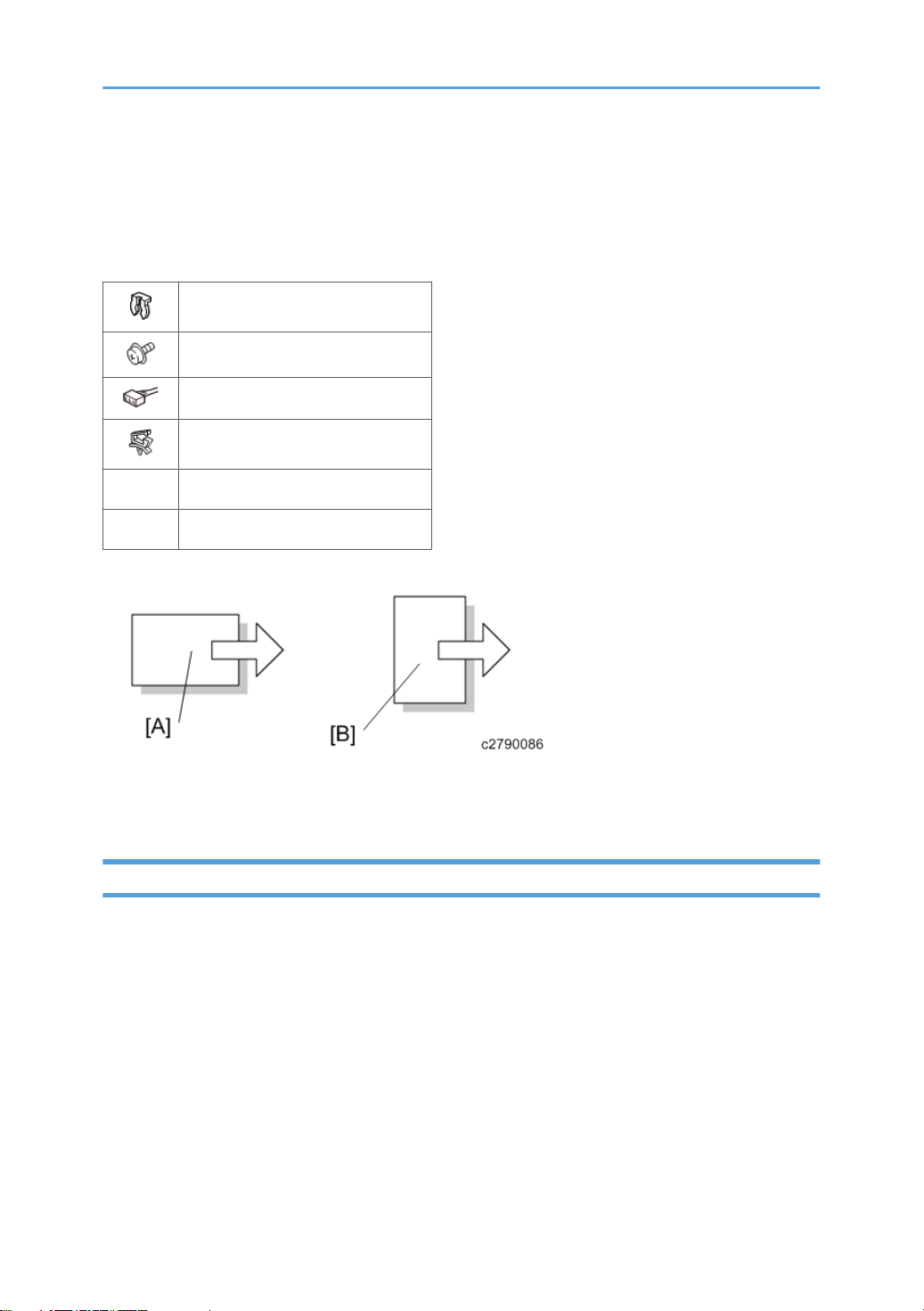
This manual uses several symbols and abbreviations. The meaning of those symbols and abbreviations
are as follows:
Clip ring
Screw
Connector
Clamp
SEF Short Edge Feed
LEF Long Edge Feed
[A] Short Edge Feed (SEF)
[B] Long Edge Feed (LEF)
Trademarks
Microsoft®, Windows®, and MS-DOS® are registered trademarks of Microsoft Corporation in the
United States and /or other countries.
PostScript® is a registered trademark of Adobe Systems, Incorporated.
PCL® is a registered trademark of Hewlett-Packard Company.
Ethernet® is a registered trademark of Xerox Corporation.
PowerPC® is a registered trademark of International Business Machines Corporation.
Other product names used herein are for identification purposes only and may be trademarks of their
respective companies. We disclaim any and all rights involved with those marks.
2

TABLE OF CONTENTS
Revision Lists........................................................................................................................................................1
Safety and Symbols............................................................................................................................................2
Trademarks.....................................................................................................................................................2
1. Replacement and Adjustment
Drive Motor Unit.................................................................................................................................................5
Upper Paper Exit Sensor....................................................................................................................................9
Left Paper Exit Sensor.......................................................................................................................................13
Upper Paper Exit Tray Set Switch...................................................................................................................14
Paper Exit Switching Unit Set Switch..............................................................................................................15
3

4
 Loading...