

Ricoh M116, M117 Service Manual

M116/M117
SERVICE MANUAL

It is the reader' s resp onsibili ty when discuss ing th e info rmation c ontained
within this document to maintain a level of confidentiality that is in the best
interest of Ricoh Americas Corporation and its member companies.
NO PART OF THIS DOCUMENT MAY BE REPRODUCED IN ANY
FASHION AND DISTRIBUTED WITHOUT THE PRIOR
PERMISSION OF RICOH AMERICAS CORPORATION.
All product names, domain names or product illustrations, including
desktop images, used in this document are trademarks, registered
trademarks or the property of their respective companies.
They are us ed thr ou gh out this book in an i nf orm a ti on al o r editorial fas hi o n
only and for the benefit of such companies. No such use, or the use of
any trad e name, or web si te is int ended to convey e ndorsement or other
affiliation with Ricoh products.
2012 RICOH Americas Corporation. All rights reserved.

The Service Manual contains information
regarding service techniques, procedures,
processes and spare parts of office equipment
distributed by Ricoh Americas Corporation.
Users of this manual should be either service
trained or cer tified by successfull y completing a
Ricoh Technic al Trai ning Progr am .
Untrained and uncertified users utilizing
information contained in this service manual to
repair or modify Ricoh equipment risk personal
injury, damage to property or loss of warranty
protection.
Ricoh Americas Corporation
WARNING
LEGEND
PRODUCT
CODE
COMPANY
LANIER RICOH SAVIN
M116 SP 3500N Aficio SP 3500N SP 3500N
M117 SP 3510DN Aficio SP 3510DN SP 3510DN
DOCUMENTATION HI S TORY
REV. NO.
DATE
COMMENTS
*
05/2012
Original Printing

SM 1 M116/M117
M116/M117
TABLE OF CONTENTS
1. PRODUCT INFORMATION ........................................................... 1-1
1.1 SPECIFICATIONS ..................................................................................... 1-1
1.2 MACH INE OVERVIEW .............................................................................. 1-2
1.2.1 CO MPONENT LAYOUT ................................................................... 1-2
1.2.2 PAPER PAT H ................................................................................... 1-3
1.2.3 DRIVE LAYOUT ............................................................................... 1-3
1.3 MACHINE CONFIGURATION ................................................................... 1-4
2. INSTALLATION ............................................................................. 2-1
2.1 I NSTALLATION REQUIREMENTS ............................................................ 2-1
2.1.1 ENVIRONMENT ............................................................................... 2-1
2.1.2 MACHI NE LEVEL ............................................................................. 2-2
2.1.3 MACHI NE SPACE REQUIREMENT ................................................. 2-2
2.1.4 POWER REQUI REMENTS .............................................................. 2-3
2.1.5 IN STALLATION PROCEDURE ........................................................ 2-3
3. PREVENTIVE MAINTENANCE..................................................... 3-1
3.1 PM I NTERVALS ......................................................................................... 3-1
3.1.1 PM PARTS ....................................................................................... 3-1
3.1.2 YIELD COUNTER ............................................................................. 3-1
Counter Reset ...................................................................................... 3-2
4. REPLACEMENT AND ADJUSTMENT ......................................... 4-1
4.1 BEFORE YOU START ............................................................................... 4-1
4.2 SPECIAL TOOLS ....................................................................................... 4-1
4.3 EXTERIOR COVERS ................................................................................ 4-2
4.3.1 FRONT COVER ................................................................................ 4-2
4.3.2 LEFT COVER ................................................................................... 4-4
4.3.3 REAR COVER .................................................................................. 4-6
4.3.4 RIGHT COVER ................................................................................. 4-7
4.3.5 TOP COVER ..................................................................................... 4-8
When installing the top cover ............................................................... 4-8
4.3.6 OPER ATION PANEL ........................................................................ 4-9

M116/M117 2 SM
4.4 LASER UNIT ............................................................................................ 4-10
4.4.1 CAUTIO N DECAL L OCATIONS ..................................................... 4-10
4.4.2 LASER UNIT ................................................................................... 4-11
4.4.3 POLYGON MIRROR MOTOR ........................................................ 4-12
4.5 PAPER FEED AND E XIT ......................................................................... 4-13
4.5.1 PAPER FEED ROLLER .................................................................. 4-13
After installing a new paper feed roller ............................................... 4-13
4.5.2 FRICTION PAD .............................................................................. 4-14
4.5.3 PAPER END SENSOR ................................................................... 4-14
4.5.4 BY-PASS FEED ROLLER .............................................................. 4-15
4.5.5 BY-PASS FEED ROLLER FRICTIO N PAD .................................... 4-16
4.5.6 BY-PASS FEED SENSOR .............................................................. 4-17
4.5.7 PAPER FEED CLUTCH .................................................................. 4-17
4.5.8 RELAY CLUTCH ............................................................................ 4-18
4.5.9 REGISTRATION CLUTCH ............................................................. 4-19
4.5.10 TONER END SENSOR ............................................................ 4-19
4.5.11 PAPER EXIT SENSOR ............................................................ 4-20
4.5.12 RELAY SENSOR ..................................................................... 4-20
4.5.13 INVERTER SENSOR ............................................................... 4-20
4.5.14 REGISTRATION ROLLER AND SENSOR .............................. 4-21
4.6 PAPER TRANSFER ................................................................................ 4-24
4.6.1 TRANSFER ROLLER ..................................................................... 4-24
After installing a new transfer roller .................................................... 4-24
4.7 FUSING ................................................................................................... 4-25
4.7.1 FUSING UNIT ................................................................................. 4-25
Reinstallation ...................................................................................... 4-27
After installing a new fusing unit ......................................................... 4-27
4.7.2 THERMOSTAT ............................................................................... 4-28
4.7.3 THERMISTOR ................................................................................ 4-29
4.7.4 FUSING LAMP ............................................................................... 4-30
When reinstall the fusing lamp ........................................................... 4-31
4.7.5 HOT ROLLER ................................................................................. 4-32
4.7.6 PRESSURE ROLLER ..................................................................... 4-33
4.7.7 HO T ROLLER ST RIPPER PAWLS................................................. 4-33
4.8 MOTORS ................................................................................................. 4-34
4.8.1 MAIN MOTOR ................................................................................ 4-34
4.8.2 DUPLEX MOTOR (FOR M117) ...................................................... 4-34
4.9 ELECTRICAL CO MPONENTS ................................................................ 4-35

SM 3 M116/M117
4.9.1 LAYOUT OF PC BOAR DS ............................................................. 4-35
ECB (Engine Controller Board) .......................................................... 4-36
EEPROM ............................................................................................ 4-37
Controller Board ................................................................................. 4-38
4.9.2 PSU ................................................................................................ 4-38
4.9.3 CHARGE TERMINAL CASE ........................................................... 4-42
4.10 OTHERS ............................................................................................ 4-43
4.10.1 COOLING FAN ........................................................................ 4-43
4.10.2 QUENCHING LAMP ................................................................ 4-43
4.11 IMAGE ADJUSTMENT ....................................................................... 4-45
4.11.1 REGISTRAT ION ADJUSTMENT ............................................. 4-45
User Adjustment ................................................................................. 4-45
Service Adjustment ............................................................................ 4-45
5. SYSTEM MAINTENANCE REFERENCE ..................................... 5-1
5.1 SERVICE PROGRAM MODE .................................................................... 5-1
5.1.1 OVERVIEW ...................................................................................... 5-1
5.1.2 ENTERING ENGINE MAINTENANCE MODE .................................. 5-1
5.1.3 SERVI CE MODE MENU ................................................................... 5-1
Selecting an Item.................................................................................. 5-1
Going into the Next Level/ Returning to the Previous Level ................. 5-1
Exiting the Service Mode Menu ............................................................ 5-1
Menu List .............................................................................................. 5-2
5.2 CO NFIGURATION AND MAINTENANCE PAGE .................................... 5-12
5.2.1 OVERVIEW .................................................................................... 5-12
To Print the Configuration Page/ Maintenance Page ......................... 5-12
Other Types of Reports ...................................................................... 5-12
Total Counter ..................................................................................... 5-13
5.3 FIRMWARE UPDATING .......................................................................... 5-14
5.3.1 CHECKING THE M ACHINE FIRMWARE VERSION ...................... 5-14
5.3.2 UPDATING THE CONTROLLER FIRMWARE ............................... 5-14
Procedure ........................................................................................... 5-14
5.3.3 UPDATING THE ENGINE FIRMWARE .......................................... 5-16
Procedure ........................................................................................... 5-16
5.3.4 UPDATING THE BOOT LOADER FIRMWARE .............................. 5-17
5.3.5 UPDATING FAILURE ..................................................................... 5-17
5.3.6 FW UPDATE TOOL MESSAGES ................................................... 5-18
FW Update Tool Messages: Information ............................................ 5-18
FW Update Tool Messages: Error ...................................................... 5-21

M116/M117 4 SM
6. TROUBLESHOOTING................................................................... 6-1
6.1 SERVICE CALL CONDITIONS .................................................................. 6-1
6.1.1 SUMMARY ....................................................................................... 6-1
Fusing related SCs ............................................................................... 6-1
6.1.2 ENG INE SC ...................................................................................... 6-2
SC 2xx (Laser Optics Error) ................................................................. 6-2
SC 4xx (Image Transfer and Transfer Error) ........................................ 6-3
SC 5xx (Motor and Fusing Error).......................................................... 6-4
SC 6xx (Communication and Other Error) ............................................ 6-8
6.2 IMAGE PROBLEMS .................................................................................. 6-9
6.2.1 OVERVIEW ...................................................................................... 6-9
6.2.2 TEST PAGE PRINTI NG .................................................................. 6-10
Test Page Print Procedure ................................................................. 6-10
6.2.3 TEST PATTERN PRINTING ........................................................... 6-10
Test Pattern Print Procedure .............................................................. 6-10
6.2.4 DARK LINES IN HALFTONE AREAS AT 75MM INTERVALS ....... 6-11
6.3 JAM .......................................................................................................... 6-12
6.3.1 JAM SENSOR LAYOUT ................................................................. 6-12
Paper Jam .......................................................................................... 6-12
6.3.2 JAM MESSAGE LIST ..................................................................... 6-13
Paper Jam .......................................................................................... 6-13
7. ENERGY SAVER ........................................................................... 7-1
7.1 ENERGY SAVER MODES......................................................................... 7-1
7.1.1 TIMER SETTINGS ............................................................................ 7-1
7.1.2 RETURN TO STAND-BY MODE ...................................................... 7-2
7.1.3 RECOMMENDATION ....................................................................... 7-2
7.2 PAPER SAV E ............................................................................................ 7-3
7.2.1 EFFECTIVENESS OF DUPLEX/COMBINE FUNCTION .................. 7-3
1. Duplex: ............................................................................................. 7-3
2. Combine mode: ................................................................................ 7-3
3. Duplex + Combine: ........................................................................... 7-3
Total counter ........................................................................................ 7-4

READ THIS FIRST
Safety Notices
Important Safety Notices
Prevention of Physical Injury
1. Before disassembling or assembling parts of the machine and peripherals, make sure that the
machine power cord is unplugged.
2. The wall outlet should be near the machine and easily accessible.
3. If any adjustment or operation check has to be made with exterior covers off or open while the
main switch is turned on, keep hands away from electrified or mechanically driven
components.
4. The machine drives some of its components when it completes the warm-up period. Be
careful to keep hands away from the mechanical and electrical components as the machine
starts operation.
5. The inside and the metal parts of the fusing unit become extremely hot while the machine is
operating. Be careful to avoid touching those components with your bare hands.
Health Safety Conditions
Toner is non-toxic, but if you get either of them in your eyes by accident, it may cause temporary
eye discomfort. Try to remove with eye drops or flush with water as first aid. If unsuccessful, get
medical attention.
Observance of Electrical Safety Standards
The machine and its peripherals must be serviced by a customer service representative who has
completed the training course on those models.
Safety and Ecological Notes for Disposal
1. Do not incinerate toner bottles or used toner. Toner dust may ignite suddenly when exposed
to an open flame.
2. Dispose of used toner, the maintenance unit which includes developer or the organic
photoconductor in accordance with local regulations. (These are non-toxic supplies.)
3. Dispose of replaced parts in accordance with local regulations.
To prevent a fire or explosion, keep the machine away from flammable liquids, gases,
and aerosols. A fire or an explosion might occur.

M116/M117 6 SM
Handling Toner
Work carefully when removing paper jams or replacing toner bottles or cartridges to avoid
spilling toner on clothing or the hands.
If toner is inhaled, immediately gargle with large amounts of cold water and move to a well
ventilated location. If there are signs of irritation or other problems, seek medical attention.
If toner gets on the skin, wash immediately with soap and cold running water.
If toner gets into the eyes, flush the eyes with cold running water or eye wash. If there are
signs of irritation or other problems, seek medical attention.
If toner is swallowed, drink a large amount of cold water to dilute the ingested toner. If there
are signs of any problem, seek medical attention.
If toner spills on clothing, wash the affected area immediately with soap and cold water. Never
use hot water! Hot water can cause toner to set and permanently stain fabric.
Always store toner and developer supplies such as toner and developer packages, cartridges,
and bottles (including used toner and empty bottles and cartridges) out of the reach of
children.
Always store fresh toner supplies or empty bottles or cartridges in a cool, dry location that is
not exposed to direct sunlight.
Do not use the cleaner to suck spilled toner (including used toner). Sucked toner may
cause firing or explosion due to electrical contact flickering inside the cleaner. However, it
is possible to use the cleaner designed for dust explosion-proof purpose. If toner is
spilled over the floor, sweep up spilled toner slowly and clean remainder with wet cloth.
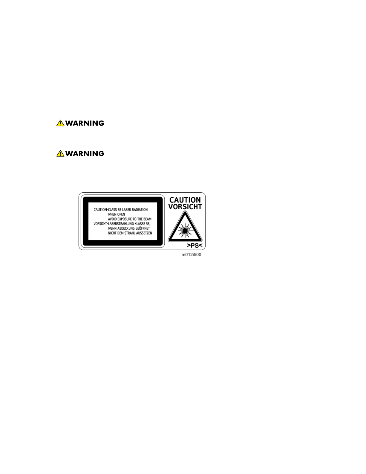
Laser Safety
The Center for Devices and Radiological Health (CDRH) prohibits the repair of laser-based optical
units in the field. The optical housing unit can only be repaired in a factory or at a location with the
requisite equipment. The laser subsystem is replaceable in the field by a qualified Customer
Engineer. The laser chassis is not repairable in the field. Customer engineers are therefore
directed to return all chassis and laser subsystems to the factory or service depot when
replacement of the optical subsystem is required.
Use of controls, or adjustment, or performance of procedures other than those specified
in this manual may result in hazardous radiation exposure.
Turn off the main switch before attempting any of the procedures in the Laser Optics
Housing Unit section. Laser beams can seriously damage your eyes.
CAUTION MARKING:
M116/M117 8 SM
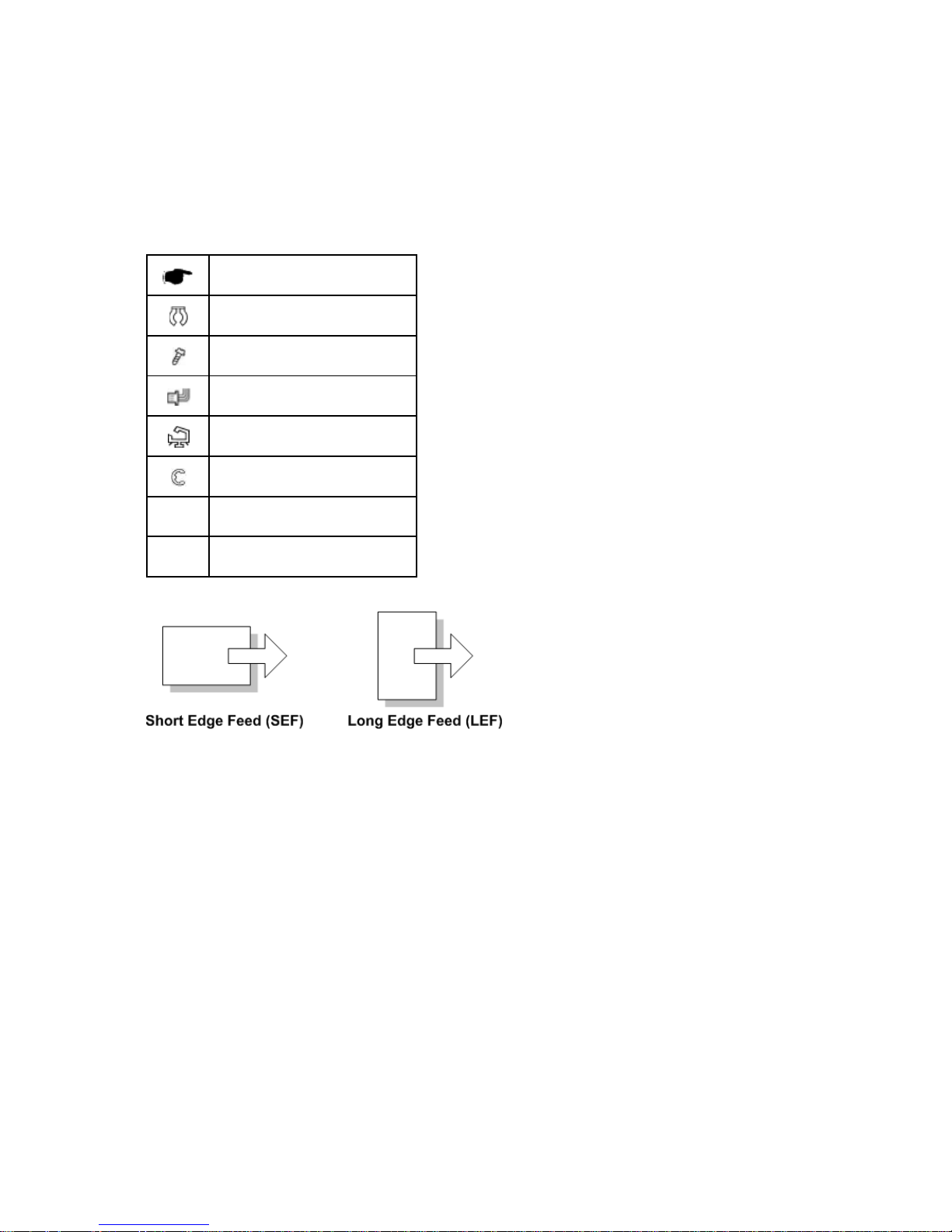
Symbols, Abbreviations and Trademarks
This manual uses several symbols and abbreviations. The meaning of those symbols and
abbreviations are as follows:
See or Refer to
Clip ring
Screw
Connector
Clamp
E-ring
SEF Short Edge Feed
LEF Long Edge Feed
Trademarks
Microsoft®, Windows®, and MS-DOS® are registered trademarks of Microsoft Corporation in the
United States and /or other countries.
PostScript
®
is a registered trademark of Adobe Systems, Incorporated.
PCL
®
is a registered trademark of Hewlett-Packard Company.
Ethernet
®
is a registered trademark of Xerox Corporation.
PowerPC
®
is a registered trademark of International Business Machines Corporation.
Other product names used herein are for identification purposes only and may be trademarks of
their respective companies. We disclaim any and all rights involved with those marks.
PRODUCT INFORMATION
REVISION HISTORY
Page Date Added/Updated/New
None


Specifications
SM 1-1 M116/M117
Product
Information
1. PRODUCT INFORMATION
1.1 SPECIFICATIONS
See "Appendices" for the following information:
"General Specifications"
"Printer"
"Supported Paper Sizes"
Machine Overview
M116/M117 1-2 SM
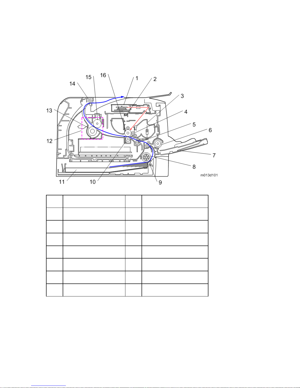
1.2 MACHI N E OVERVI EW
1.2.1 COMPONENT LAYOUT
1. Laser unit 9. Friction pad
2. Quenching lamp 10. Transfer roller
3. Cartridge (AIO-type) 11. Paper Tray
4. Development roller 12. Fusing Unit
5. Registration roller 13. Pressure Roller
6. By-pass feed roller 14. Paper exit roller
7. By-pass feed tray 15. Hot Roller
8. Paper feed roller 16. Drum

Machine Overview
SM 1-3 M116/M117
Product
Information
1.2.2 PAPER PATH
[A] Duplex section (For M117)
[B] Standard paper tray unit
[C] Optional paper tray unit
1.2.3 DRIVE LAYOUT
1. Duplex Motor
2. Main Motor
3. Registration Clutch
4. Relay Clutch
5. Paper Feed Clutch
Machine Configuration
M116/M117 1-4 SM
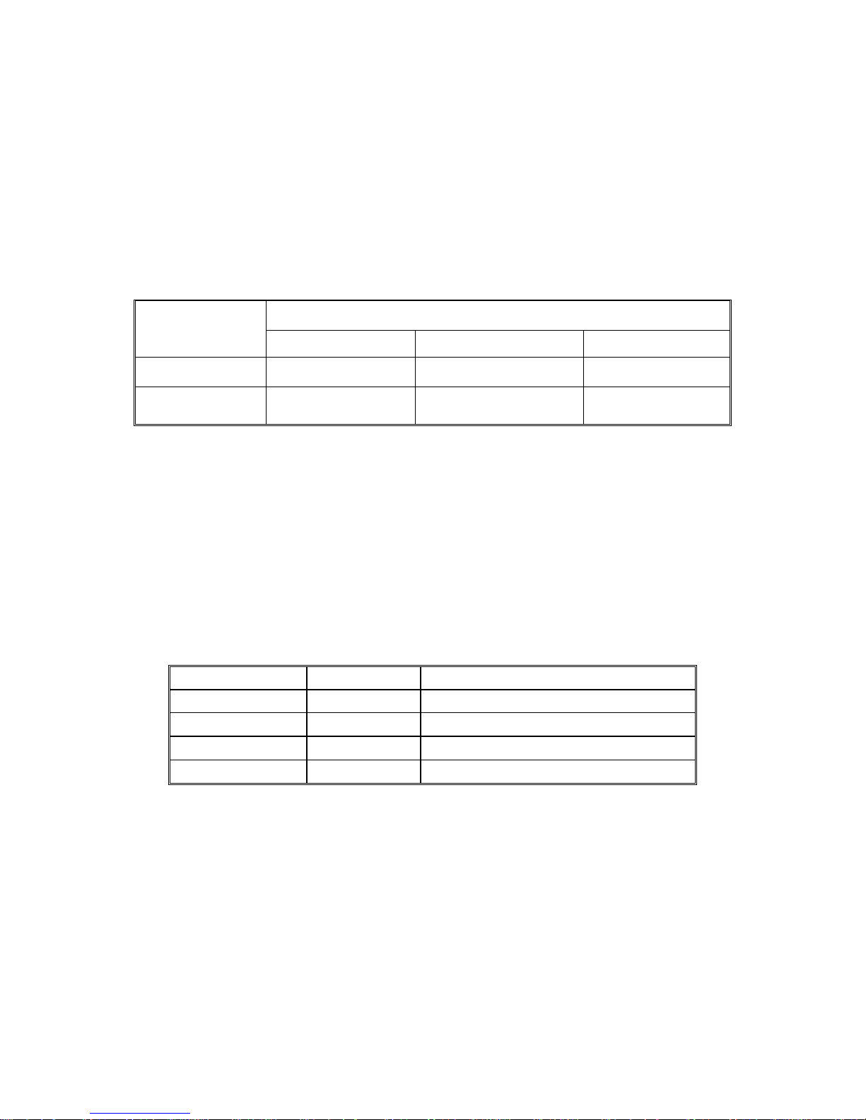
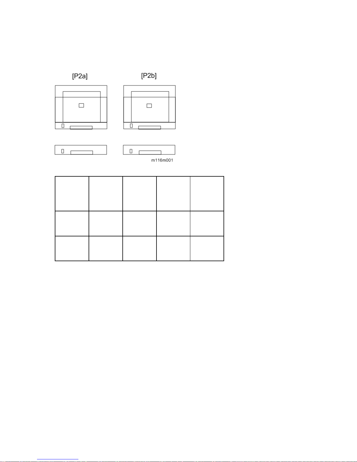
1.3 MACHINE CONFIGURATION
Models
Duplex
Unit
Optional
Memory
Optional
Tray
(M355)
PCL PS
RN-P2a
(M116)
NA NA 250x1 Yes
RN-P2b
(M117)
Auto NA 250x1 Yes
NA: Not Availab le

INSTALLATION
REVISION HISTORY
Page Date Added/Updated/New
None


Installation Requirements
SM 2-1 M116/M117
Installation
2. INSTALLATION
2.1 INSTALLATION REQUIREMENTS
2.1.1 ENVIRONMENT
This machine, which uses high voltage power sources, can generate ozone gas. High
ozone density is harmful to human health. Therefore, the machine must be installed in a
well-ventilated room.
1. Temperature Rage: 10°C to 32°C (50°F to 89.6°F)
2. Humidity Range: 15% to 80% RH
3. Ambient Illumination: Less than 2,000 lux (do not expose to direct sunlight)
4. Ventilation: 3 times/hr/person
5. Do not put the machine in areas with sudden temperature changes. This includes:
Areas directly exposed to cool air from air conditioning
Areas directly exposed to heat from a heating system.
6. Do not put the machine in areas exposed to corrosive gas.
7. Do not install the machine at locations over 2,000 m (6,562 ft.) above sea level.
8. Put the machine on a strong, level base. (Tilting towards any side must be no more than 3
mm.)
9. Do not put the machine in areas with strong vibrations.
Installation Requirements
M116/M117 2-2 SM
2.1.2 MACHINE LEVEL
Front to back: Within 5 mm (0.2") of level
Right to left: Within 5 mm (0.2") of level
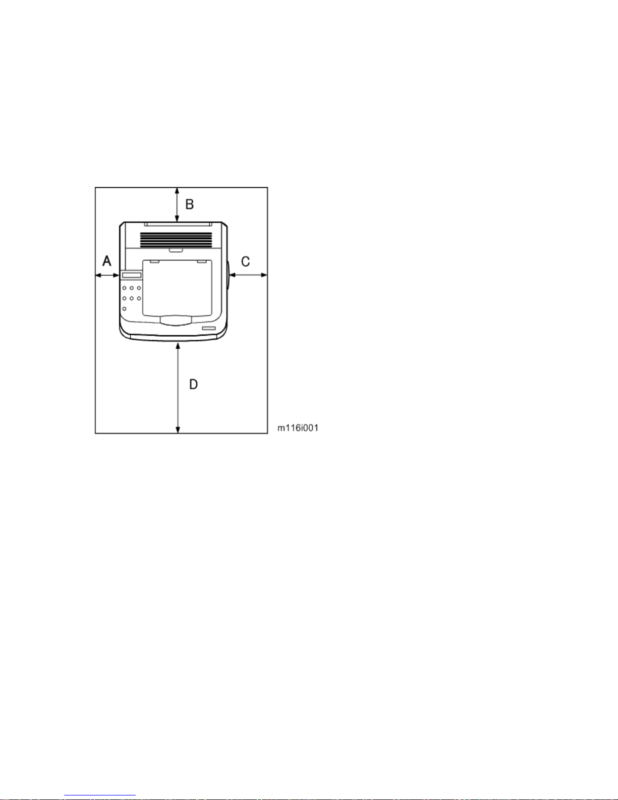
2.1.3 MACHINE SPACE REQUIREMENT
Put the machine near a power source with these clearances:
A: Over 10 cm (4")
B: Over 20 cm (7.9")
C: Over 20 cm (7.9")
D: Over 70 cm (27.6")
Installation Requirements
SM 2-3 M116/M117
Installation
2.1.4 POWER REQUIREMENTS
Make sure that the plug is tightly in the outlet.
Avoid multi-wiring.
Make sure that you ground the machine.
Input voltage level
NA: 120 V, TW: 110 V, 60 Hz: Less than 10 A
EU/ Asia/ CHN: 220 V to 240 V, 50 Hz/60 Hz: Less than 5 A
Permitted voltage fluctuation: 10%
Do not set anything on the power cord.
2.1.5 INSTALLATION PROCEDURE
Refer to the "Hardware Guide".


PREVENTIVE MAINTENANCE
REVISION HISTORY
Page Date Added/Updated/New
None

PM Intervals
SM 3-1 M116/M117
Preventive
Maintenance
3. PREVENTIVE MAINTENANCE
3.1 PM INTERVALS
3.1.1 PM PARTS
There are no PM parts in this machine.
Other than the three Yield Parts listed below, there are essentially no PM parts required
for this product.
These three items will need to be replaced in cases where their yield is near, however,
given the APV (Average Printer Volume) for this product, these "yield parts*
1
" are
expected to outlast the working life of the machine.
*
1
"Yield Parts": Parts whose expected yield is longer than the machine lifetime when taking into
consideration the machine's APV.
Description Expected Yield Q'ty/unit
Paper Feed Roller 120 K prints 1
Transfer Roller 120 K prints 1
Fusing Unit 120 K prints 1
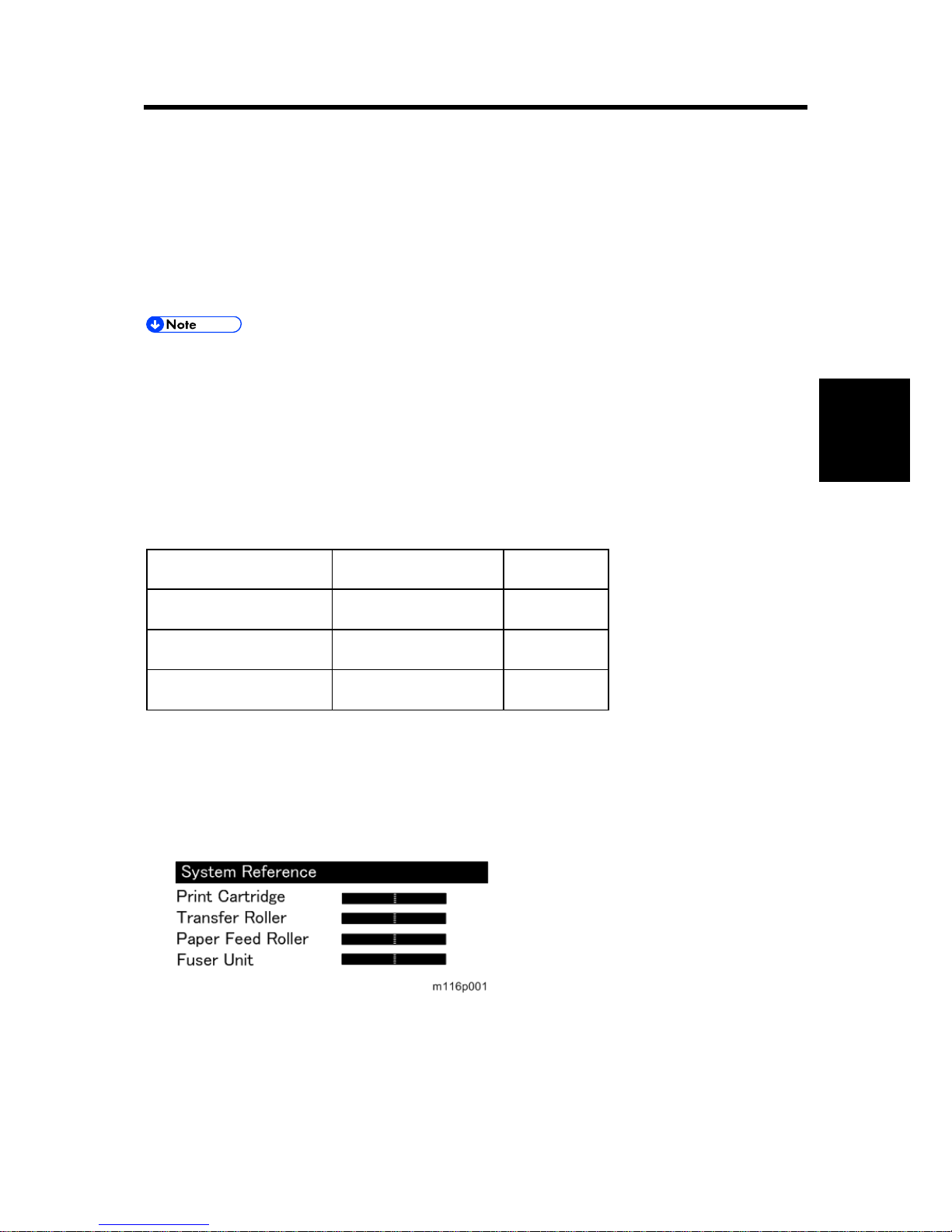
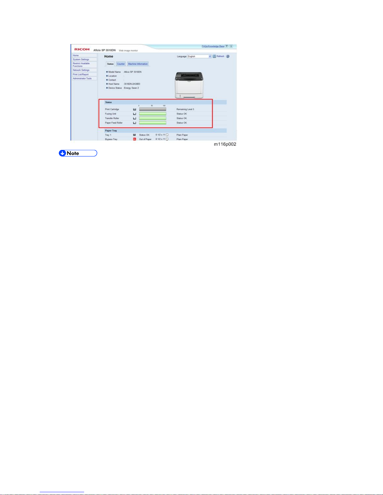
3.1.2 YIELD COUNTER
Yield counters for each yield part can be checked by the following methods.
Configuration Pa ge in the “List/Test Print” menu
Web Image Monitor
PM Intervals
M116/M117 3-2 SM
The machine displays "Fuser life end notice", "Transfer roller life end notice" or "Life End
of Paper Feed Roller Unit" when one of these counters reaches each yield.
Counter Reset
The process below shows how to reset the yield counters.
1. Enter the "Service Mode".
2. Select "Eng Maintenance", and then press "OK" key.
3. Select "Reset FuserUnit", "Reset Trans Rol" or "Reset Feed " and then press "OK" key.
4. Select “Execute” and the press “OK” key.
5. Exit the Service Mode".
REPLACEMENT AND ADJUSTMENT
REVISION HISTORY
Page Date Added/Updated/New
None

 Loading...