

Ricoh M080 Service Manual

M080
SERVICE MANUAL


M080
SERVICE MANUAL


M080
SERVICE MANUAL


It is the reader's responsibility when discussing the information contained
within this document to maintain a level of confidentiality that is in the best
interest of Ricoh Americas Corporation and its member companies.
NO PART OF THIS DOCUMENT MAY BE REPRODUCED IN ANY
F ASHION AND DISTRIBUTED WITHOUT THE PRIOR
PERMISSION OF RICOH AMERICAS CORPORATION.
All product names, domain names or product illustrations, including
desktop images, used in this document are trademarks, registered
trademarks or the property of their respective companies.
They are used throughout this book in an informational or editorial fashion
only and for the benefit of such companies. No such use, or the use of
any trade name, or web site is intended to convey endorsement or other
affiliation with Ricoh products.
© 2011 RICOH Americas Corporation. All rights reserved.


The Service Manual contains information
regarding service techniques, procedures,
processes and spare parts of office equipment
distributed by Ricoh Americas Corporation.
Users of this manual should be either service
trained or certified by successfully completing a
Ricoh Technical Training Program.
Untrained and uncertified users utilizing
information contained in this service manual to
repair or modify Ricoh equipment risk personal
injury, damage to property or loss of warranty
protection.
Ricoh Americas Corporation
WARNING


LEGEND
PRODUCT
CODE
COMPANY
GESTETNER LANIER RICOH SAVIN
M080 SP 4310N SP 4310N SP 4310N SP 4310N
DOCUMENTATION HISTORY
REV. NO. DATE COMMENTS
*
08/2011 Original Printing


SM i M080
M080
TABLE OF CONTENTS
PRODUCT INFORMATION
1. PRODUCT INFORMATION .......................................................... 1-1
1.1SPECIFICATIONS ..................................................................................... 1-1
1.2MACHINE CONFIGURATION ................................................................... 1-2
1.2.1 SYSTEM COMPONENTS ................................................................ 1-2
1.3OVERVIEW ................................................................................................ 1-4
1.3.1 MECHANICAL COMPONENT LAYOUT ........................................... 1-4
1.3.2 PAPER PATH ................................................................................... 1-5
INSTALLATION
2. INSTALLATION ............................................................................ 2-1
2.1INSTALLATION REQUIREMENTS ............................................................ 2-1
2.1.1 ENVIRONMENT ............................................................................... 2-1
2.1.2 MACHINE LEVEL ............................................................................. 2-2
2.1.3 REQUIRED SPACE .......................................................................... 2-2
2.1.4 POWER SUPPLY ............................................................................. 2-3
2.2MACHINE INSTALLATION ........................................................................ 2-4
2.3SD CARD APPLICATION MOVE ............................................................... 2-5
2.3.1 OVERVIEW ...................................................................................... 2-5
2.3.2 MOVE EXEC .................................................................................... 2-6
2.3.3 UNDO EXEC .................................................................................... 2-7
PREVENTIVE MAINTENANCE
3. PREVENTIVE MAINTENANCE .................................................... 3-1
3.1USER MAINTENANCE .............................................................................. 3-1
3.2SERVICE MAINTENANCE ........................................................................ 3-2

M080 ii SM
REPLACEMENT AND ADJUSTMENT
4. REPLACEMENT AND ADJUSTMENT ........................................ 4-1
4.1GENERAL .................................................................................................. 4-1
4.1.1 PRECAUTIONS ON DISASSEMBLY ............................................... 4-1
4.1.2 RELEASING PLASTIC LATCHES .................................................... 4-2
4.1.3 AFTER SERVICING THE MACHINE ................................................ 4-2
4.2SPECIAL T OOLS ....................................................................................... 4-3
4.3COVERS .................................................................................................... 4-4
4.3.1 UPPER COVER ................................................................................ 4-4
4.3.2 LEFT COVER ................................................................................... 4-5
4.3.3 BY-PASS TRAY UNIT ...................................................................... 4-5
4.3.4 FRONT COVER ................................................................................ 4-6
4.3.5 RIGHT COVER ................................................................................. 4-6
4.4LASER UNIT .............................................................................................. 4-7
4.4.1 CAUTION DECAL LOCATIONS ....................................................... 4-7
4.4.2 POLYGON MIRROR MOTOR .......................................................... 4-8
4.4.3 LASER SYNCHRONIZATION DETECTOR ...................................... 4-9
4.4.4 LASER UNIT ..................................................................................... 4-9
4.4.5 LASER DIODE UNIT ...................................................................... 4-10
4.4.6 LASER BEAM PITCH ADJUSTMENT ............................................ 4-11
4.5TRANSFER ROLLER .............................................................................. 4-13
4.6TONER END SENSOR ............................................................................ 4-14
4.7FUSING ................................................................................................... 4-15
4.7.1 FUSING UNIT ................................................................................. 4-15
4.7.2 HOT ROLLER AND FUSING LAMP ............................................... 4-16
4.7.3 PRESSURE ROLLER ..................................................................... 4-18
4.7.4 THERMISTOR AND THERMOSTAT .............................................. 4-19
4.7.5 HOT ROLLER STRIPPERS ............................................................ 4-20
4.8PAPER FEED .......................................................................................... 4-21
4.8.1 PAPER FEED ROLLER .................................................................. 4-21
4.8.2 FRICTION PAD .............................................................................. 4-22
4.9BY-PASS TRAY ....................................................................................... 4-23
4.10 PRINTER CONTROLLER BOARD .................................................... 4-24
4.11 ENGINE BOARD ................................................................................ 4-25
4.12 MAIN MOTOR .................................................................................... 4-26
4.13 CLUTCHES ........................................................................................ 4-27

SM iii M080
4.13.1 BY-PASS FEED CLUTCH AND RELAY CLUTCH ..................... 4-28
4.13.2 PAPER FEED CLUTCH AND REGISTRATION CLUTCH .......... 4-29
4.14 PSU, HVPS ........................................................................................ 4-30
4.15 FANS .................................................................................................. 4-32
4.15.1 COOLING FAN ........................................................................... 4-32
4.15.2 PSU FAN .................................................................................... 4-33
SERVICE MAINTENANCE REFERENCE
5. SYSTEM MAINTENANCE REFERENCE ..................................... 5-1
5.1SERVICE PROGRAM MODE .................................................................... 5-1
5.1.1 SP TABLES ...................................................................................... 5-1
5.1.2 INPUTTING A VALUE OR SETTING FOR A SERVICE PROGRAM 5-2
5.1.3 EXITING SERVICE MODE ............................................................... 5-2
5.2UPDATING THE FIRMWARE .................................................................... 5-3
5.2.1 TYPE OF FIRMWARE ...................................................................... 5-3
5.2.2 PRECAUTIONS ................................................................................ 5-4
Handling SD Cards .............................................................................. 5-4
Upload/Download ................................................................................. 5-4
Network Connection ............................................................................. 5-4
5.2.3 MACHINE FIRMWARE UPDATE ..................................................... 5-5
5.2.4 ERROR RECOVERY ........................................................................ 5-6
Controller .............................................................................................. 5-6
Engine .................................................................................................. 5-7
5.3POWER-ON SELF TESTS ........................................................................ 5-8
5.4DIP SWITCHES ......................................................................................... 5-9
5.4.1 CONTROLLER BOARD .................................................................... 5-9
TROUBLESHOOTING
6. TROUBLESHOOTING ................................................................. 6-1
6.1SERVICE CALL CONDITIONS .................................................................. 6-1
6.2ERROR MESSAGES ................................................................................. 6-2
6.3GENERAL TROUBLESHOOTING ............................................................. 6-7
6.3.1 IMAGE ADJUSTMENT ..................................................................... 6-7
Registration Adjustment ....................................................................... 6-7
Parallelogram Image Adjustment ......................................................... 6-7
6.3.2 ELECTRICAL DEFECTS .................................................................. 6-8

M080 iv SM
6.3.3 SKEW ADJUSTMENT .................................................................... 6-11
6.3.4 STREAKS IN THE SUB SCAN DIRECTION .................................. 6-12
6.3.5 MISCELLANEOUS PROBLEMS .................................................... 6-13
ENERGY SAVING
7. ENERGY SAVING ........................................................................ 7-1
7.1ENERGY SAVE ......................................................................................... 7-1
7.1.1 ENERGY SAVER MODES ............................................................... 7-1
Auto Off Mode Setting .......................................................................... 7-1
Auto Off Scheduler Setting ................................................................... 7-2
ECO Night Sensor ................................................................................ 7-2
Return to Standby Mode ...................................................................... 7-3
7.2PAPER SAVE ............................................................................................ 7-4
7.2.1 EFFECTIVENESS OF DUPLEX/COMBINE FUNCTION .................. 7-4
1. Duplex: ............................................................................................. 7-4
2. Combine mode: ................................................................................ 7-4
3. Duplex + Combine: ........................................................................... 7-5
Recommendation ................................................................................. 7-5
Duplex Mode Tables ............................................................................ 7-6
M080 SERVICE MANUAL APPENDICES
SEE M080 SERVICE MANUAL APPENDICES SECTION FOR DETAILED TABLE OF
CONTENTS
DUPLEX UNIT AD 1000 (G893)
SEE SECTION G893 FOR DETAILED TABLE OF CONTENTS
PAPER FEED UNIT TK1030 & ENVELOPE FEEDER TYPE
400 (G894/G362)
SEE SECTION G894/G362 FOR DETAILED TABLE OF CONTENTS

PRODUCT INFORMATION
APPENDIX: SPECIFICATIONS
(G894) PAPER FEED UNIT TK1030
(G362) ENVELOPE FEEDER TYPE 400
INSTALLATION
APPENDIX: TROUBLESHOOTING GUIDE
PREVENTIVE MAINTENANCE
APPENDIX: SP MODE TABLES
REPLACEMENT AND ADJUSTMENT
SERVICE MAINTENANCE REFERENCE
(G893) DUPLEX UNIT AD 1000
TROUBLESHOOTING
ENERGY SAVING
TAB
POSITION 2
TAB
POSITION 1
TAB
POSITION 3
TAB
POSITION 4
TAB
POSITION 6
TAB
POSITION 5
TAB
POSITION 8
TAB
POSITION 7


READ THIS FIRST
Safety Notices
Important Safety Notices
Prevention of Physical Injury
1. Before disassembling or assembling parts of the machine and peripherals, make sure that
the machine power cord is unplugged.
2. The wall outlet should be near the machine and easily accessible.
3. If any adjustment or operation check has to be made with exterior covers off or open while
the main switch is turned on, keep hands away from electrified or mechanically driven
components.
4. The machine drives some of its components when it completes the warm-up period. Be
careful to keep hands away from the mechanical and electrical components as the machine
starts operation.
5. The inside and the metal parts of the fusing unit become extremely hot while the machine is
operating. Be careful to avoid touching those components with your bare hands.
Health Safety Conditions
Toner is non-toxic, but if you get either of them in yo ur eyes by accident, it may cause temporary
eye discomfort. Try to remove with eye drops or flush with water as first aid. If unsuccessful, get
medical attention.
Observance of Electrical Safety Standards
The machine and its peripherals must be serviced by a customer service representative who
has completed the training course on those models.
The Controller board on this machine contains a lithium battery. The danger of
explosion exists if a battery of this type is incorrectly replaced. Replace only with the
same or an equivalent type recommended by the manufacturer. Discard batteries in
accordance with the manufacturer's instructions and local regulations.

Safety and Ecological Notes for Disposal
1. Do not incinerate toner bottles or used toner. Toner dust may ignite suddenly when
exposed to an open flame.
2. Dispose of used toner, the maintenance unit which includes developer or the organic
photoconductor in accordance with local regulations. (These are non-toxic supplies.)
3. Dispose of replaced parts in accordance with local regulations.
To prevent a fire or explosion, keep the machine away from flammable liquids, gases,
and aerosols. A fire or an explosion might occur.
Handling Toner
Work carefully when removing paper jams or replacing toner bottles or cartridges to avoid
spilling toner on clothing or the hands.
If toner is inhaled, immediately gargle with large amounts of cold water and move to a well
ventilated location. If there are signs of irritation or other problems, seek medical attention.
If toner gets on the skin, wash immediately with soap and cold running water.
If toner gets into the eyes, flush the eyes with cold running water or eye wash. If there are
signs of irritation or other problems, seek medical attention.
If toner is swallowed, drink a large amount of cold water to dilute the ingested toner. If there
are signs of any problem, seek medical attention.
If toner spills on clothing, wash the affected area immediately with soap and cold water.
Never use hot water! Hot water can cause toner to set and permanently stain fabric.
Always store toner and developer supplies such as toner and developer packages,
cartridges, and bottles (including used toner and empty bottles and cartridges) out of the
reach of children.
Always store fresh toner supplies or empty bottles or cartridges in a cool, dry location that is
not exposed to direct sunlight.
Laser Safety
The Center for Devices and Radiological Health (CDRH) prohibits the repair of laser-based
optical units in the field. The optical housing unit can only be repaired in a factory or at a
location with the requisite equipment. The laser subsystem is replaceable in the field by a
qualified Customer Engineer. The laser chassis is not repairable in the field. Customer
engineers are therefore directed to return all chassis and laser subsystems to the factory or
service depot when replacement of the optical subsystem is required.
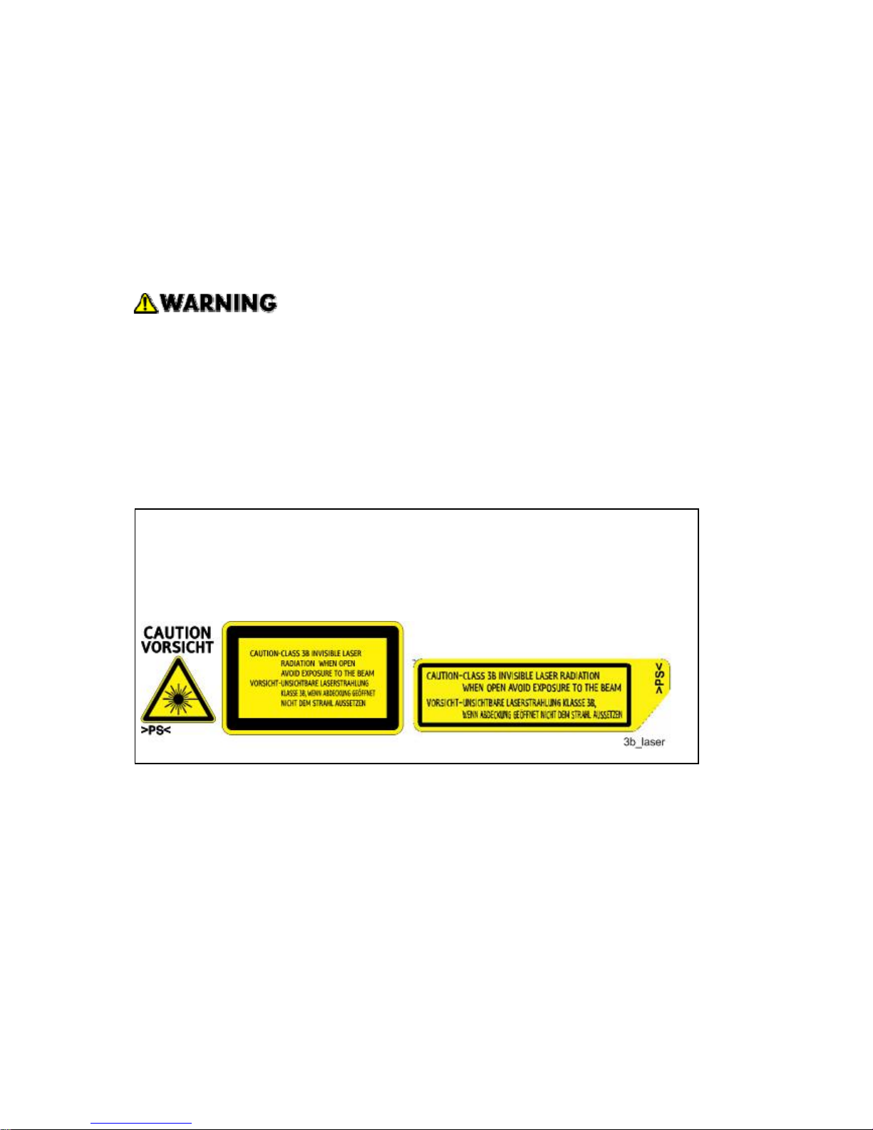
Use of controls, or adjustment, or performance of procedures other than those
specified in this manual may result in hazardous radiation exposure.
WARNING:
Turn off the main switch before attempting any of the procedures in the Laser Unit
section. Laser beams can seriously damage your eyes.
CAUTION MARKING:
Conventions and Trademarks
Conventions
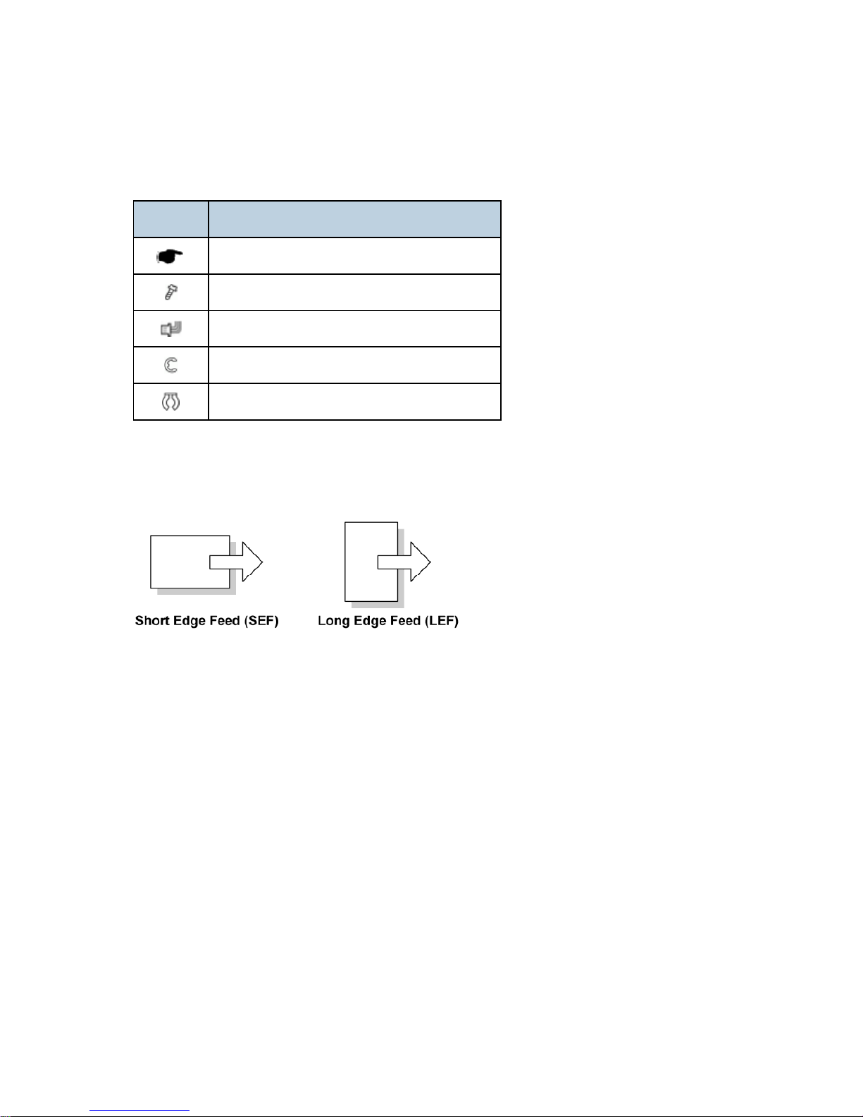
Symbol What it means
Refer to section number
Screw
Connector
E-ring
C-ring
The following notations are used in text to describe the direction of paper feed: lengthwise and
sideways. The annotations "SEF" and "LEF" denote "Short Edge Feed" and "Long Edge Feed".
(The arrows indicate the direction of paper feed.)
Trademarks
Microsoft®, Windows®, and MS-DOS® are registered trademarks of Microsoft Corporation in the
United States and /or other countries.
PostScript
®
is a registered trademark of Adobe Systems, Incorporated.
PCL
®
is a registered trademark of Hewlett-Packard Company.
Ethernet
®
is a registered trademark of Xerox Corporation.
PowerPC
®
is a registered trademark of International Business Machines Corporation.
Other product names used herein are for identification purposes only and may be trademarks of
their respective companies. We disclaim any and all rights involved with those marks.
This manual uses several symbols and some simple abbreviations.

PRODUCT INFORMATION
REVISION HISTORY
Page Date Added/Updated/New
None


Specifications
SM 1-1 M080
Product
Information
1. PRODUCT INFORMATION
1.1 SPECIFICATIONS
See the "Appendices Section" for the "General Specifications".
Machine Configuration
M080 1-2 SM
1.2 MACHINE CONFIGURATION
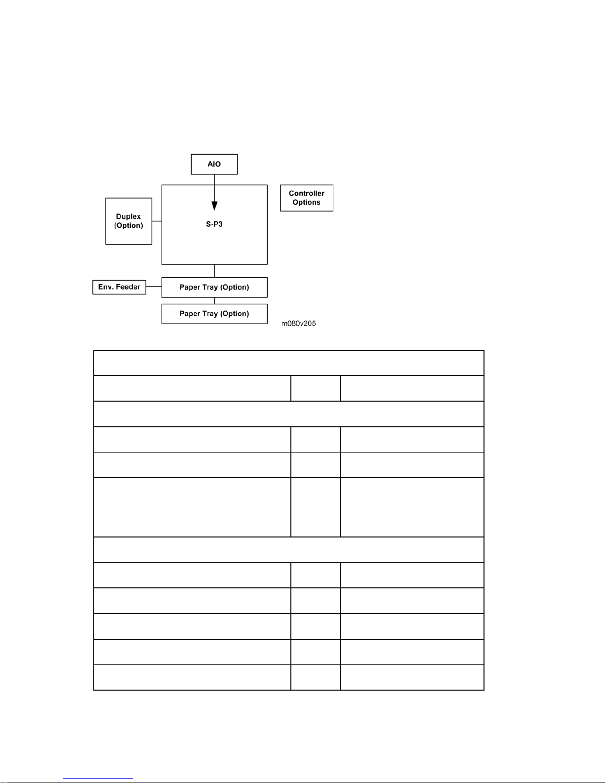
1.2.1 SYSTEM COMPONENTS
Main
Mainframe (37 ppm) M080 37 ppm (LT - SEF)
Options
Paper Feed Unit TK1030 G894 1 or 2 trays can be installed.
Duplex Unit AD1000 G893
Envelope Feeder Type 400 G362
If 2 PFUs are installed, the
envelope feeder must go in the
top tray.
Internal Options
Memory Unit Type G 128 MB M345
Memory Unit Type G 256 MB D362
Hard Disk Drive Type 4310 M394
IEEE 1284 Interface Board Type A B679
IEEE 802.11a/g interface Unit Type L M344 For NA

Machine Configuration
SM 1-3 M080
Product
Information
IEEE 802.11a/g Interface Unit Type M M344 For EU
Gigabit Ethernet Board Type C M394 For NA
VM Card Type O M385
Data Storage Card Type A G874
IPDS Unit Type 4310 M394
SD card for NetWare printing Type G M394
Overview
M080 1-4 SM
1.3 OVERVIEW
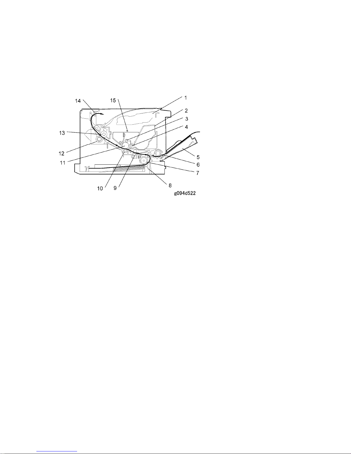
1.3.1 MECHANICAL COMPONENT LAYOUT
1. Laser unit
2. Cartridge (AIO-type)
3. Charge roller
4. Development roller
5. By-pass feed tray
6. By-pass feed roller
7. Paper feed roller
8. Friction pad
9. Registration roller
10. Transfer roller
11. Drum
12. Pressure roller
13. Hot roller
14. Paper exit roller
15. Quenching lamp
Overview
SM 1-5 M080
Product
Information
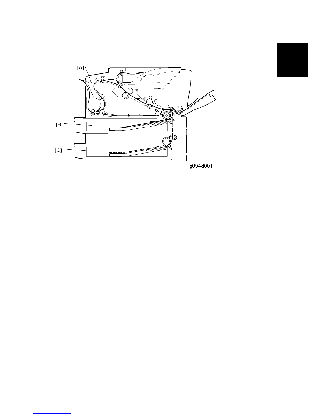
1.3.2 PAPER PATH
[A] Optional duplex unit
[B] Standard paper tray unit
[C] Optional paper tray unit

 Loading...