

Ricoh M016, M017 Service Manual

M016/M017
SERVICE MANUAL
005432MIU


M016/M017
SERVICE MANUAL


M016/M017
SERVICE MANUAL
005432MIU


It is the reader's responsibility when discussing the information contained
within this document to maintain a level of confidentiality that is in the best
interest of Ricoh Americas Corporation and its member companies.
NO PART OF THIS DOCUMENT MAY BE REPRODUCED IN ANY
F ASHION AND DISTRIBUTED WITHOUT THE PRIOR
PERMISSION OF RICOH AMERICAS CORPORATION.
All product names, domain names or product illustrations, including
desktop images, used in this document are trademarks, registered
trademarks or the property of their respective companies.
They are used throughout this book in an informational or editorial fashion
only and for the benefit of such companies. No such use, or the use of
any trade name, or web site is intended to convey endorsement or other
affiliation with Ricoh products.
© 2009 RICOH Americas Corporation. All rights reserved.


The Service Manual contains information
regarding service techniques, procedures,
processes and spare parts of office equipment
distributed by Ricoh Americas Corporation.
Users of this manual should be either service
trained or certified by successfully completing a
Ricoh Technical Training Program.
Untrained and uncertified users utilizing
information contained in this service manual to
repair or modify Ricoh equipment risk personal
injury, damage to property or loss of warranty
protection.
Ricoh Americas Corporation
WARNING


LEGEND
PRODUCT
CODE
COMPANY
GESTETNER LANIER RICOH SAVIN
M016 SP3400SF SP3400SF SP3400SF SP3400SF
M017 SP3410SF SP3410SF SP3410SF SP3410SF
DOCUMENTATION HISTORY
REV. NO. DATE COMMENTS
*
11/2009 Original Printing


SM i M016/M017
M016/M017
TABLE OF CONTENTS
PRODUCT INFORMATION
1. PRODUCT INFORMATION ....................................................... 1-1
1.1SPECIFICATIONS ................................................................................. 1-1
1.2MACHINE OVERVIEW .......................................................................... 1-2
1.2.1 COMPONENT LAYOUT ............................................................... 1-2
1.2.2 PAPER PATH ............................................................................... 1-3
1.2.3 DRIVE LAYOUT ............................................................................ 1-4
1.3MACHINE CONFIGURATION ............................................................... 1-5
INSTALLATION
2. INSTALLATION ........................................................................ 2-1
2.1INSTALLATION REQUIREMENTS ........................................................ 2-1
2.1.1 ENVIRONMENT ........................................................................... 2-1
2.1.2 MACHINE LEVEL ......................................................................... 2-1
2.1.3 MACHINE SPACE REQUIREMENT ............................................. 2-2
2.1.4 POWER REQUIREMENTS ........................................................... 2-2
2.1.5 INSTALLATION PROCEDURE ..................................................... 2-2
PREVENTIVE MAINTENANCE
3. PREVENTIVE MAINTENANCE ................................................ 3-1
3.1PM INTERVALS ..................................................................................... 3-1
3.1.1 PM PARTS .................................................................................... 3-1
3.1.2 YIELD COUNTER ......................................................................... 3-1
Counter Reset .................................................................................. 3-2

M016/M017 ii SM
REPLACEMENT AND ADJUSTMENT
4. REPLACEMENT AND ADJUSTMENT ..................................... 4-1
4.1BEFORE YOU ST ART ........................................................................... 4-1
4.2SPECIAL TOOLS ................................................................................... 4-2
4.3EXTERIOR COVERS ............................................................................. 4-3
4.3.1 FRONT COVER ............................................................................ 4-3
4.3.2 LEFT COVER ............................................................................... 4-4
4.3.3 REAR COVER .............................................................................. 4-7
4.3.4 RIGHT COVER ............................................................................. 4-7
4.3.5 TOP COVER ................................................................................. 4-9
When installing the top cover ........................................................... 4-9
4.4ADF ...................................................................................................... 4-11
4.4.1 ADF UNIT ................................................................................... 4-11
4.4.2 ORIGINAL TRAY ........................................................................ 4-12
4.4.3 ADF FEED UNIT ......................................................................... 4-12
4.4.4 ADF SEPARATION PAD ............................................................ 4-13
4.4.5 ADF FRONT COVER .................................................................. 4-13
4.4.6 ADF REAR COVER .................................................................... 4-14
4.4.7 ADF COVER ............................................................................... 4-14
4.4.8 ADF MOTOR .............................................................................. 4-15
4.4.9 ORIGINAL SET SENSOR ........................................................... 4-17
4.4.10 ADF COVER OPEN SENSOR ................................................ 4-18
4.4.11 ADF FEED SENSOR .............................................................. 4-19
4.4.12 ADF DRIVE BOARD ............................................................... 4-20
4.5SCANNER UNIT .................................................................................. 4-21
4.5.1 OPERATION PANEL .................................................................. 4-22
4.5.2 SCANNER TOP COVER ............................................................ 4-23
4.5.3 SCANNER CARRIAGE UNIT ..................................................... 4-24
4.5.4 EXPOSURE LAMP ..................................................................... 4-26
When reinstalling the exposure lamp ............................................. 4-27
4.5.5 LAMP STABILIZER BOARD ....................................................... 4-28
4.5.6 SCANNER MOTOR .................................................................... 4-29
4.6LASER UNIT ........................................................................................ 4-30
4.6.1 CAUTION DECAL LOCATIONS ................................................. 4-30
4.6.2 LASER UNIT ............................................................................... 4-31

SM iii M016/M017
4.6.3 POLYGON MIRROR MOTOR .................................................... 4-32
4.7PAPER FEED AND EXIT ..................................................................... 4-33
4.7.1 PAPER FEED ROLLER .............................................................. 4-33
After installing a new paper feed roller ........................................... 4-33
4.7.2 FRICTION PAD ........................................................................... 4-34
4.7.3 PAPER END SENSOR ............................................................... 4-34
4.7.4 BY-PASS FEED ROLLER ........................................................... 4-35
4.7.5 BY-PASS FEED ROLLER FRICTION PAD ................................ 4-36
4.7.6 BY-PASS FEED SENSOR .......................................................... 4-37
4.7.7 PAPER FEED CLUTCH .............................................................. 4-37
4.7.8 RELAY CLUTCH ......................................................................... 4-39
4.7.9 REGISTRATION CLUTCH .......................................................... 4-39
4.7.10 TONER END SENSOR ........................................................... 4-40
4.7.11 PAPER EXIT SENSOR ........................................................... 4-40
4.7.12 RELAY SENSOR .................................................................... 4-41
4.7.13 INVERTER SENSOR .............................................................. 4-41
4.7.14 REGISTRATION ROLLER AND SENSOR ............................. 4-42
4.8PAPER TRANSFER ............................................................................. 4-46
4.8.1 TRANSFER ROLLER ................................................................. 4-46
After installing a new transfer roller ................................................ 4-46
4.9FUSING ............................................................................................... 4-47
4.9.1 FUSING UNIT ............................................................................. 4-47
Reinstallation .................................................................................. 4-49
After installing a new fusing unit ..................................................... 4-49
4.9.2 THERMOSTAT ........................................................................... 4-50
4.9.3 THERMISTOR ............................................................................ 4-51
4.9.4 FUSING LAMP ............................................................................ 4-52
When reinstall the fusing lamp ....................................................... 4-53
4.9.5 HOT ROLLER ............................................................................. 4-53
4.9.6 PRESSURE ROLLER ................................................................. 4-54
4.9.7 HOT ROLLER STRIPPER PAWLS ............................................. 4-54
4.10 MOTORS........................................................................................ 4-55
4.10.1 MAIN MOTOR......................................................................... 4-55
4.10.2 DUPLEX MOTOR (FOR M017) .............................................. 4-55
4.11 ELECTRICAL COMPONENTS ....................................................... 4-56
4.11.1 LAYOUT OF PC BOARDS ..................................................... 4-56

M016/M017 iv SM
ECB (Engine Controller Board) ...................................................... 4-57
EEPROM ........................................................................................ 4-58
Controller Board ............................................................................. 4-58
FCU ................................................................................................ 4-59
USB Host Board ............................................................................. 4-60
4.11.2 PSU ........................................................................................ 4-61
4.11.3 CHARGE TERMINAL CASE ................................................... 4-65
4.12 OTHERS ........................................................................................ 4-66
4.12.1 COOLING FAN ....................................................................... 4-66
4.12.2 SPEAKER ............................................................................... 4-66
4.12.3 QUENCHING LAMP ............................................................... 4-67
4.13 IMAGE ADJUSTMENT ................................................................... 4-68
4.13.1 REGISTRATION ADJUSTMENT ............................................ 4-68
User Adjustment ............................................................................. 4-68
Service Adjustment ........................................................................ 4-68
SYSTEM MAINTENANCE REFERENCE
5. SYSTEM MAINTENANCE REFERENCE ................................. 5-1
5.1SERVICE PROGRAM MODE ................................................................ 5-1
5.1.1 OVERVIEW ................................................................................... 5-1
5.1.2 MAINTENANCE MODE MENU ..................................................... 5-1
To access Maintenance Mode do the following: ............................... 5-1
Selecting an Item .............................................................................. 5-1
Going into the Next Level/ Returning to the Previous Level ............. 5-1
Exiting the Maintenance Mode Menu ............................................... 5-1
Menu List .......................................................................................... 5-2
5.1.3 FAX SERVICE TEST MENU ....................................................... 5-20
Entering the Fax Service Test Menu .............................................. 5-20
Selecting an Item ............................................................................ 5-20
Going into the Next Level/ Returning to the Previous Level ........... 5-20
Exiting the Maintenance Mode Menu ............................................. 5-20
Menu List ........................................................................................ 5-21
5.2CONFIGURATION AND MAINTENANCE PAGE ................................. 5-23
5.2.1 OVERVIEW ................................................................................. 5-23
To Print the Configuration Page/ Maintenance Page ..................... 5-23

SM v M016/M017
Other Types of Reports .................................................................. 5-24
Total Counter .................................................................................. 5-24
5.3FIRMWARE UPDATING ...................................................................... 5-25
5.3.1 CHECKING THE MACHINE FIRMWARE VERSION .................. 5-25
5.3.2 UPDATING THE CONTROLLER FIRMWARE ........................... 5-25
Procedure ....................................................................................... 5-25
5.3.3 UPDATING THE ENGINE FIRMWARE ...................................... 5-27
Procedure ....................................................................................... 5-27
5.3.4 UPDATING THE BOOT LOADER FIRMWARE .......................... 5-28
5.3.5 UPDATING FAILURE ................................................................. 5-29
5.3.6 FW UPDATE TOOL MESSAGES ............................................... 5-30
FW Update Tool Messages: Information ........................................ 5-30
FW Update Tool Messages: Error .................................................. 5-34
TROUBLESHOOTING
6. TROUBLESHOOTING .............................................................. 6-1
6.1SERVICE CALL CONDITIONS .............................................................. 6-1
6.1.1 SUMMARY .................................................................................... 6-1
Fusing related SCs ........................................................................... 6-1
6.1.2 ENGINE SC .................................................................................. 6-2
SC 2xx (Laser Optics Error) ............................................................. 6-2
SC 4xx (Image Transfer and Transfer Error) .................................... 6-3
SC 5xx (Motor and Fusing Error) ...................................................... 6-4
SC 6xx (Communication and Other Error) ........................................ 6-9
6.2IMAGE PROBLEMS ............................................................................. 6-10
6.2.1 OVERVIEW ................................................................................. 6-10
6.2.2 TEST PAGE PRINTING .............................................................. 6-10
Test Page Print Procedure ............................................................. 6-10
6.2.3 TEST PATTERN PRINTING ....................................................... 6-11
Test Pattern Print Procedure .......................................................... 6-11
6.2.4 DARK LINES IN HALFTONE AREAS AT 75MM INTERVALS .... 6-12
6.3JAM ...................................................................................................... 6-13
6.3.1 JAM SENSOR LAYOUT ............................................................. 6-13
Paper Jam ...................................................................................... 6-13
Original Jam ................................................................................... 6-14

M016/M017 vi SM
6.3.2 JAM MESSAGE LIST ................................................................. 6-14
Paper Jam ...................................................................................... 6-15
Original Jam ................................................................................... 6-16
ENERGY SAVING
7. ENERGY SAVING ..................................................................... 7-1
7.1ENERGY SAVE ..................................................................................... 7-1
7.1.1 ENERGY SAVER MODES ............................................................ 7-1
Timer Settings .................................................................................. 7-1
Return to Stand-by Mode ................................................................. 7-2
Recommendation ............................................................................. 7-2
7.2PAPER SAVE ........................................................................................ 7-3
7.2.1 EFFECTIVENESS OF DUPLEX/COMBINE FUNCTION .............. 7-3
1. Duplex: ......................................................................................... 7-3
2. Combine mode: ............................................................................ 7-3
3. Duplex + Combine: ....................................................................... 7-4
Total counter .................................................................................... 7-4
M016/M017 SERVICE MANUAL APPENDICES
SEE M016/M017 SERVICE MANUAL APPENDICES SECTION FOR DETAILED TABLE
OF CONTENTS
PAPER FEED UNIT TK 1080 (M355)
SEE SECTION M355 FOR DETAILED TABLE OF CONTENTS
PRODUCT INFORMATION
APPENDIX: SPECIFICATIONS
INSTALLATION
APPENDIX: SP MODE TABLES
Paper Feed Unit TK1080 (M355)
PREVENTIVE MAINTENANCE
APPENDIX: TROUBLESHOOTING GUIDE
REPLACEMENT AND ADJUSTMENT
SYSTEM MAINTENANCE REFERENCE
TROUBLESHOOTING
ENERGY SAVING
TAB
POSITION 2
TAB
POSITION 1
TAB
POSITION 3
TAB
POSITION 4
TAB
POSITION 6
TAB
POSITION 5
TAB
POSITION 8
TAB
POSITION 7


Read This First
Safety Notices
Important Safety Notices
Prevention of Physical Injury
1. Before disassembling or assembling parts of the machine and peripherals, make sure
that the machine power cord is unplugged.
2. The wall outlet should be near the machine and easily accessible.
3. If any adjustment or operation check has to be made with exterior covers off or open
while the main switch is turned on, keep hands away from electrified or mechanically
driven components.
4. The machine drives some of its components when it completes the warm-up period.
Be careful to keep hands away from the mechanical and electrical components as the
machine starts operation.
5. The inside and the metal parts of the fusing unit become extremely hot while the
machine is operating. Be careful to avoid touching those components with your bare
hands.
Health Safety Conditions
Toner is non-toxic, but if you get either of them in your eyes by accident, it may cause
temporary eye discomfort. Try to remove with eye drops or flush with water as first aid. If
unsuccessful, get medical attention.
Observance of Electrical Safety Standards
The machine and its peripherals must be serviced by a customer service representative
who has completed the training course on those models.
Safety and Ecological Notes for Disposal
1. Do not incinerate toner bottles or used toner. Toner dust may ignite suddenly when
exposed to an open flame.
2. Dispose of used toner, the maintenance unit which includes developer or the organic
photoconductor in accordance with local regulations. (These are non-toxic supplies.)
3. Dispose of replaced parts in accordance with local regulations.
To prevent a fire or explosion, keep the machine away from flammable liquids,
gases, and aerosols. A fire or an explosion might occur.
The Controller board on the MF model contains a lithium battery. The danger of
explosion exists if a battery of this type is incorrectly replaced. Replace only with
the same or an equivalent type recommended by the manufacturer. Discard
batteries in accordance with the manufacturer's instructions and local regulations
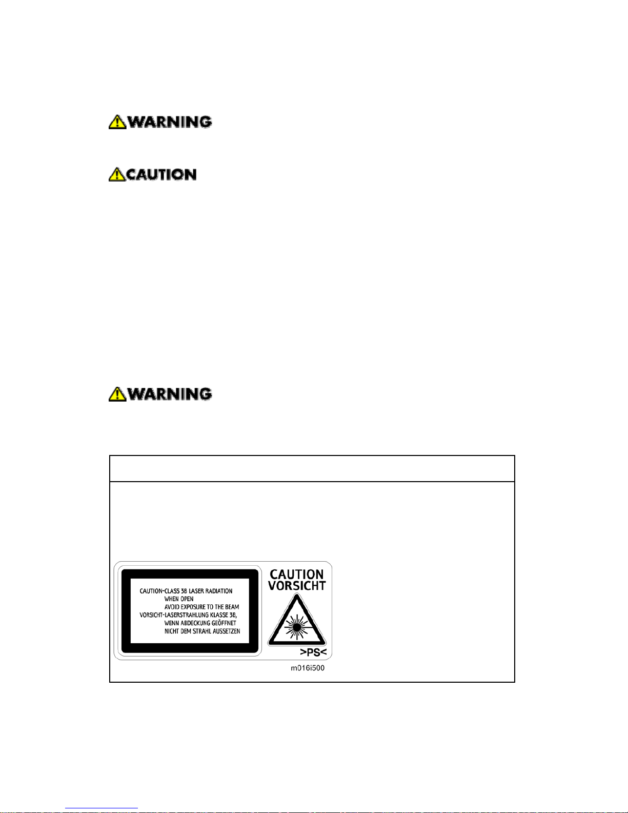
Laser Safety
The Center for Devices and Radiological Health (CDRH) prohibits the repair of laser-based
optical units in the field. The optical housing unit can only be repaired in a factory or at a
location with the requisite equipment. The laser subsystem is replaceable in the field by a
qualified Customer Engineer. The laser chassis is not repairable in the field. Customer
engineers are therefore directed to return all chassis and laser subsystems to the factory or
service depot when replacement of the optical subsystem is required.
Use of controls, or adjustment, or performance of procedures other than those
specified in this manual may result in hazardous radiation exposure.
WARNING
WARNING:
Turn off the main switch before attempting any of the procedures in the Laser Optics
Housing Unit section. Laser beams can seriously damage your eyes.
CAUTION MARKING:
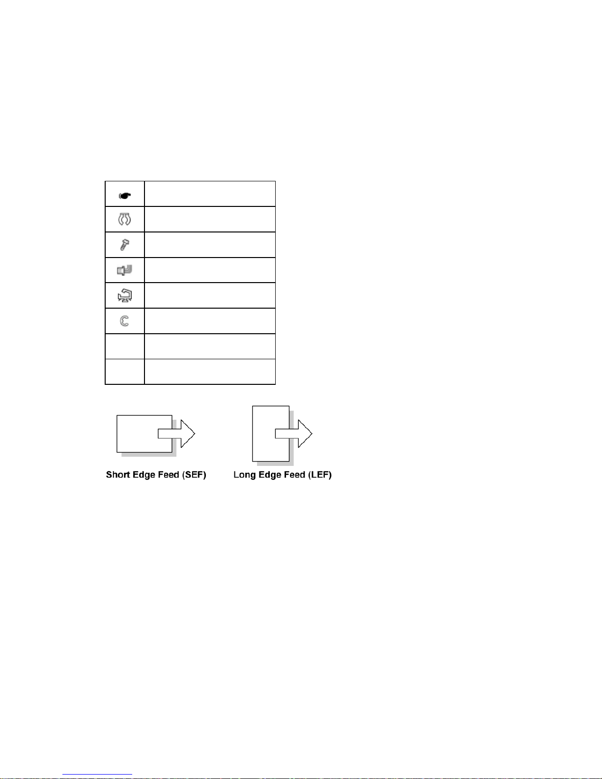
Symbols, Abbreviations and Trademarks
This manual uses several symbols and abbreviations. The meaning of those symbols and
abbreviations are as follows:
See or Refer to
Clip ring
Screw
Connector
Clamp
E-ring
SEF Short Edge Feed
LEF Long Edge Feed
Trademarks
Microsoft®, Windows®, and MS-DOS® are registered trademarks of Microsoft Corporation
in the United States and /or other countries.
PostScript
®
is a registered trademark of Adobe Systems, Incorporated.
PCL
®
is a registered trademark of Hewlett-Packard Company.
Ethernet
®
is a registered trademark of Xerox Corporation.
PowerPC
®
is a registered trademark of International Business Machines Corporation.
Other product names used herein are for identification purposes only and may be
trademarks of their respective companies. We disclaim any and all rights involved with
those marks.


PRODUCT INFORMATION
REVISION HISTORY
Page Date Added/Updated/New
None


Specifications
SM 1-1 M016/M017
Product
Information
1. PRODUCT INFORMATION
1.1 SPECIFICATIONS
See "Appendices" for the following information:
"General Specifications"
"Printer"
"Copier"
"Scanner"
"Fax"
"Supported Paper Sizes"
Machine Overview
M016/M017 1-2 SM
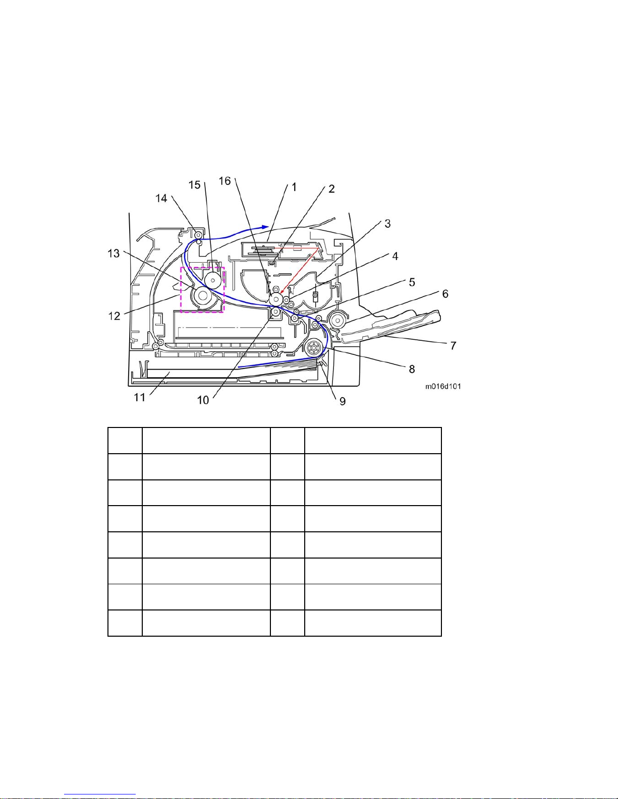
1.2 MACHINE OVERVIEW
1.2.1 COMPONENT LAYOUT
1. Laser unit 9. Friction pad
2. Quenching lamp 10. Transfer roller
3. Cartridge (AIO-type) 11. Paper Tray
4. Development roller 12. Fusing Unit
5. Registration roller 13. Pressure Roller
6. By-pass feed roller 14. Paper exit roller
7. By-pass feed tray 15. Hot Roller
8. Paper feed roller 16. Drum
Machine Overview
SM 1-3 M016/M017
Product
Information
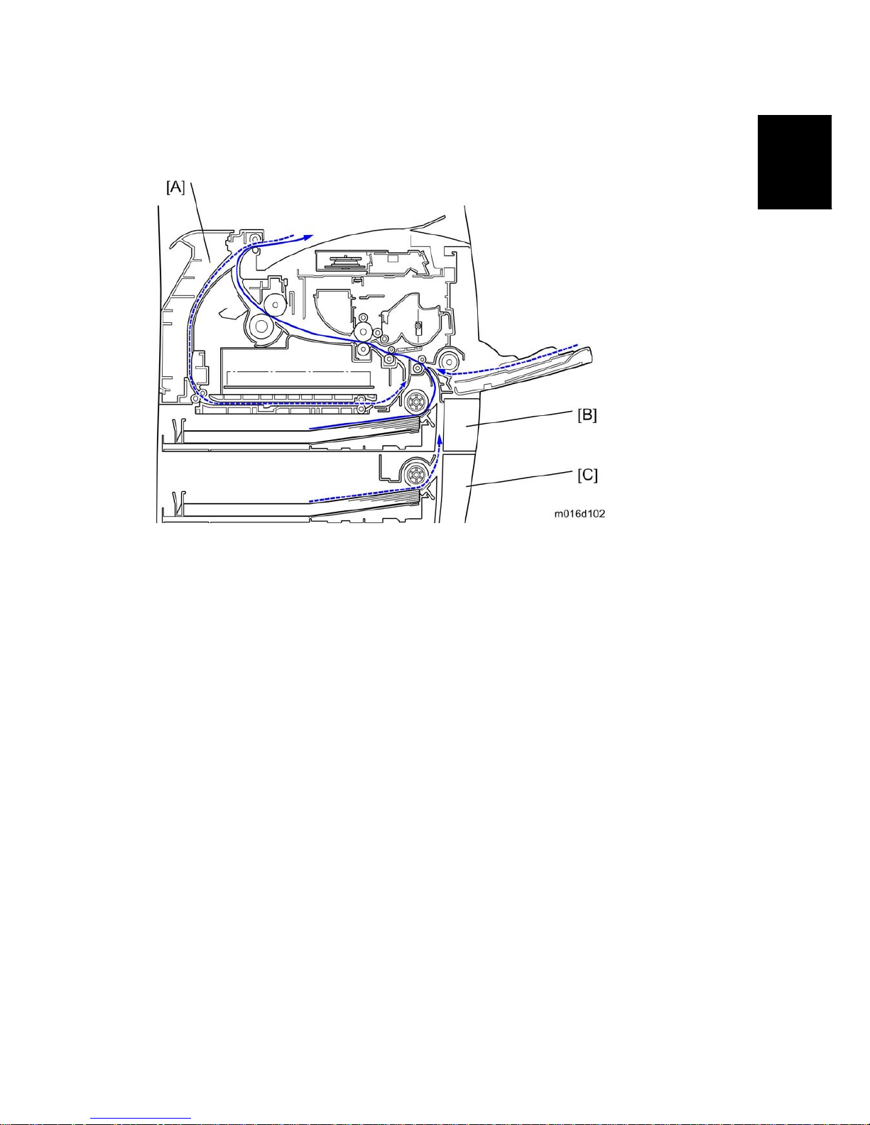
1.2.2 PAPER PATH
[A] Duplex section (For M017)
[B] Standard paper tray unit
[C] Optional paper tray unit
Machine Overview
M016/M017 1-4 SM
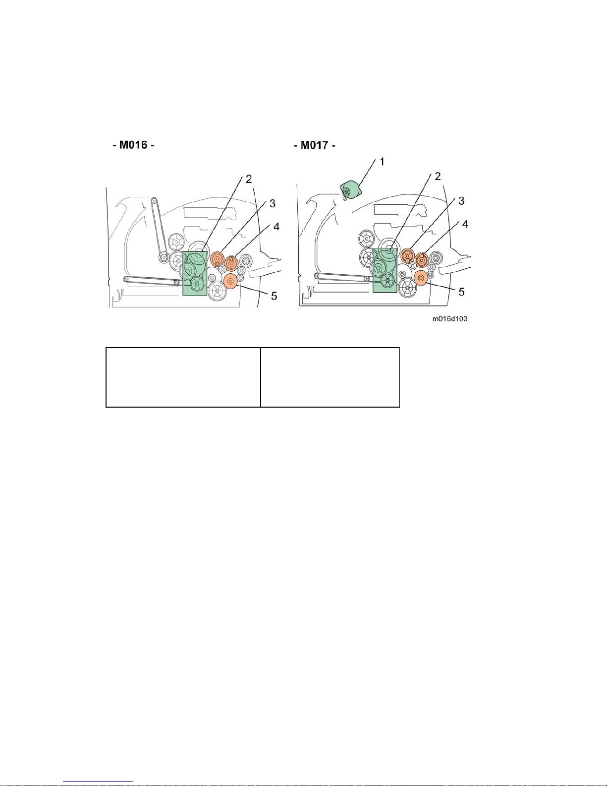
1.2.3 DRIVE LAYOUT
1. Duplex Motor
2. Main Motor
3. Registration Clutch
4. Replay Clutch
5. Paper Feed Clutch
 Loading...