

Page 1
Read this manual carefully before you use this machine and keep it handy for future reference. For safe and correct use, be sure to read the Safety Information
before using the machine.
10
8
9
11
Guide to the Printer
Installing Options
Connecting the Printer Cables
Configuration
Paper and Other Media
Replacing Consumables
Cleaning the Printer
Adjusting the Printer
Troubleshooting
Removing Misfed Paper
Appendix
1
2
3
4
5
6
7
Hardware Guide
Operating Instructions
Page 2

Introduction
This manual contains detailed instructions and notes on the operation and use of this printer. For your safety and
benefit, read this manual carefully before using the printer. Keep this manual in a handy place for quick
reference.For safe and correct use, be sure to read the "Safety Information" before using the machine.
Page 3

TABLE OF CONTENTS
Positions of WARNING and CAUTION Labels...............................................................................................5
Manuals for This Printer......................................................................................................................................7
How to Read This Manual.................................................................................................................................8
Symbols...........................................................................................................................................................8
Model-Specific Information...............................................................................................................................9
List of Options...................................................................................................................................................10
Installing the Operating Instructions...............................................................................................................11
1. Guide to the Printer
Exterior: Front View..........................................................................................................................................13
Exterior: Rear View...........................................................................................................................................15
Interior...............................................................................................................................................................16
Control Panel....................................................................................................................................................17
Display Panel....................................................................................................................................................19
Reading the Display and Using Keys.........................................................................................................19
2. Installing Options
Available Options............................................................................................................................................21
Order of Option Installation........................................................................................................................21
Where to Install Options.............................................................................................................................22
Cautions When Re-installing the Controller Board...................................................................................24
Attaching the Paper Feed Unit........................................................................................................................26
Installing the Memory Expansion Units..........................................................................................................30
Installing the SDRAM Module....................................................................................................................30
Installing the Hard Disk................................................................................................................................33
Installing the Interface Units.............................................................................................................................37
Installing the Gigabit Ethernet Board.........................................................................................................37
Installing the Wireless LAN Interface Board..............................................................................................39
Installing the IEEE 1284 Interface Board...................................................................................................43
Installing SD Card Options..............................................................................................................................46
3. Connecting the Printer Cables
Ethernet Cable Connection.............................................................................................................................49
Reading the LED Lamps...............................................................................................................................51
USB Cable Connection....................................................................................................................................52
Parallel Cable Connection..............................................................................................................................54
1
Page 4

4. Configuration
Ethernet Configuration.....................................................................................................................................55
Specifying an IP Address (No DHCP)........................................................................................................56
Receiving an IP Address Automatically (DHCP)........................................................................................58
Configuring Network Settings When Using NetWare.............................................................................60
Setting the Ethernet Speed..........................................................................................................................61
Wireless LAN Configuration...........................................................................................................................64
Setting the SSID............................................................................................................................................66
Setting Security Method of Wireless LAN......................................................................................................68
Setting a WEP Key.......................................................................................................................................68
Setting WPA.................................................................................................................................................69
Configuring WPA/WPA2...............................................................................................................................73
Installing a Site Certificate...........................................................................................................................73
Installing Device Certificate.........................................................................................................................74
Setting Items of WPA/WPA2.....................................................................................................................75
5. Paper and Other Media
Supported Paper for Each Tray.......................................................................................................................77
500-sheet Paper Trays................................................................................................................................77
2000-sheet Paper Feed Unit......................................................................................................................78
1200-sheet Paper Feed Unit......................................................................................................................78
Bypass Tray..................................................................................................................................................78
Paper Weight and Capacity.......................................................................................................................79
Paper Recommendations.................................................................................................................................80
Storing Paper................................................................................................................................................80
Types of Paper and Other Media..............................................................................................................80
Paper Not Supported by This Printer..........................................................................................................87
Print Area......................................................................................................................................................87
Loading Paper..................................................................................................................................................89
500-sheet Paper Feed Trays.......................................................................................................................89
2000-sheet Paper Feed Unit......................................................................................................................97
1200-sheet Paper Feed Unit......................................................................................................................99
Bypass Tray................................................................................................................................................102
6. Replacing Consumables
2
Page 5

Adding Toner.................................................................................................................................................109
Replacing Maintenance Kit A.......................................................................................................................114
Replacing the Development Unit..............................................................................................................114
Replacing Maintenance Kit B.......................................................................................................................121
Replacing the Transfer Unit.......................................................................................................................122
Replacing the Fusing Unit.........................................................................................................................125
Adding Staples...............................................................................................................................................129
When the 1000-sheet Finisher is Installed..............................................................................................129
When the 2 Tray Finisher is Installed.......................................................................................................133
7. Cleaning the Printer
Cautions When Cleaning..............................................................................................................................137
Cleaning the Friction Pads............................................................................................................................138
500-sheet Paper Trays..............................................................................................................................138
2000-sheet Paper Feed Unit....................................................................................................................139
1200-sheet Paper Feed Unit....................................................................................................................140
Cleaning the Registration Roller...................................................................................................................142
8. Adjusting the Printer
Adjusting Image Density................................................................................................................................145
Adjusting Printing Position.............................................................................................................................147
9. Troubleshooting
Error and Status Messages Appears on the Control Panel........................................................................151
Panel Tones....................................................................................................................................................155
Printer Does Not Print....................................................................................................................................156
Checking the Port Connection..................................................................................................................157
Printing Problems............................................................................................................................................159
Additional Troubleshooting...........................................................................................................................166
Removing Jammed Staples...........................................................................................................................168
When the 1000-sheet Finisher is Installed..............................................................................................168
When the 2 Tray Finisher is Installed.......................................................................................................170
Removing Punch Waste.................................................................................................................................173
When the 2 Tray Finisher is Installed.......................................................................................................173
10. Removing Misfed Paper
Removing Misfed Paper................................................................................................................................175
3
Page 6

Paper Misfeed Message (A).........................................................................................................................176
Paper Misfeed Message (B).........................................................................................................................178
Paper Misfeed Message (C).........................................................................................................................180
Paper Misfeed Message (D).........................................................................................................................182
Paper Misfeed Message (R).........................................................................................................................184
When the 1000-sheet Finisher is Installed..............................................................................................184
When the 2 Tray Finisher is Installed.......................................................................................................186
Paper Misfeed Message (Y).........................................................................................................................191
Paper Misfeed Message (Z).........................................................................................................................192
Paper Misfeed Message (U).........................................................................................................................194
Duplex Print Always Misfeeds......................................................................................................................198
11. Appendix
Moving and Transporting the Printer............................................................................................................201
Moving the Printer.....................................................................................................................................201
Consumables..................................................................................................................................................204
Toner...........................................................................................................................................................204
Maintenance Kit........................................................................................................................................204
Staple Cartridge........................................................................................................................................205
Specifications.................................................................................................................................................206
Mainframe.................................................................................................................................................206
Options.......................................................................................................................................................208
INDEX...........................................................................................................................................................219
4
Page 7
Positions of WARNING and CAUTION Labels
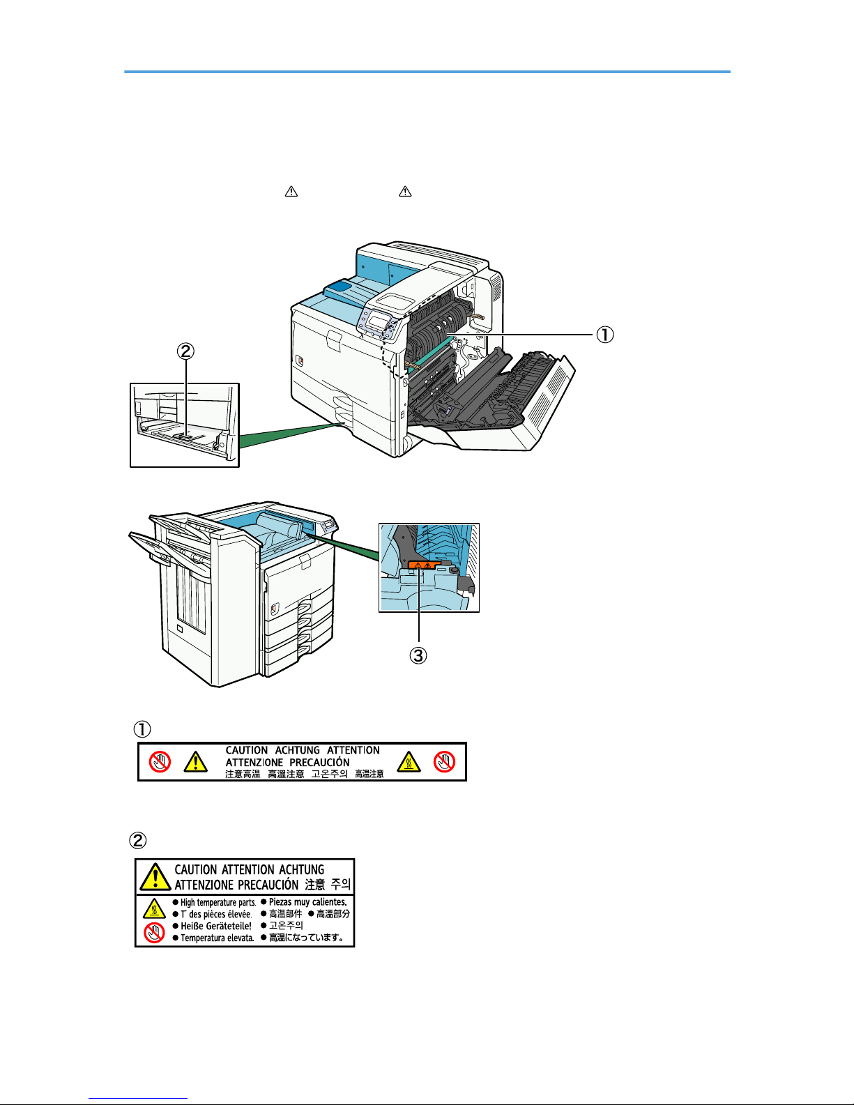
This machine has labels for WARNING and CAUTION at the positions shown below. For safety,
please follow the instructions and handle the machine as indicated.
BEK205S
BEK206S
High temperature. Be careful of hot parts when clearing paper jams.
The inside of this printer could be very hot. Do not touch parts which a label is put on. Otherwise, an injury
might occur.
5
Page 8

High temperature. Be careful of hot parts when clearing paper jams.
6
Page 9

Manuals for This Printer
Refer to the manuals that are relevant to what you want to do with the printer.
• Media differ according to manual.
• The printed and electronic versions of a manual have the same contents.
• Adobe Acrobat Reader/Adobe Reader must be installed in order to view the manuals as PDF files.
• A Web browser must be installed in order to view the html manuals.
Safety Information
Contains information about safe usage of this printer.
To avoid injury and prevent damage to the printer, be sure to read this.
Quick Installation Guide
Contains procedures for removing the printer from its box, connecting it to a computer, and installing
its driver.
Hardware Guide (This manual)
Contains information about paper and procedures such as installing options, replacing consumables,
responding to error messages, and resolving jams.
Software Guide
Contains information about using this printer, its software, and its security functions.
Security Guide
Contains information for administrators of the printer. It explains security functions that the
administrators can use to prevent data tampering or unauthorized use of the printer. Also refer to this
manual for the procedure for registering an administrator, as well as setting user and administrator
authentication.
UNIX Supplement
For "UNIX Supplement", please visit our Web site or consult an authorized dealer.
This manual includes descriptions of functions and settings that might not be available on this printer.
• Manuals provided are specific to machine types.
7
Page 10
How to Read This Manual
Symbols
This manual uses the following symbols:
Indicates important safety notes.
Ignoring these notes could result in serious injury or death. Be sure to read these notes. They can be found
in the “Safety Information” section of this manual.
Indicates important safety notes.
Ignoring these notes could result in moderate or minor injury, or damage to the machine or to property. Be
sure to read these notes. They can be found in the “Safety Information” section of this manual.
Indicates points to pay attention to when using the machine, and explanations of likely causes of paper
misfeeds, damage to originals, or loss of data. Be sure to read these explanations.
Indicates supplementary explanations of the machine's functions, and instructions on resolving user errors.
This symbol is located at the end of sections. It indicates where you can find further relevant information.
[ ]
Indicates the names of keys that appear on the machine's display panel.
[ ]
Indicates the names of keys on the machine's control panel.
8
Page 11
Model-Specific Information
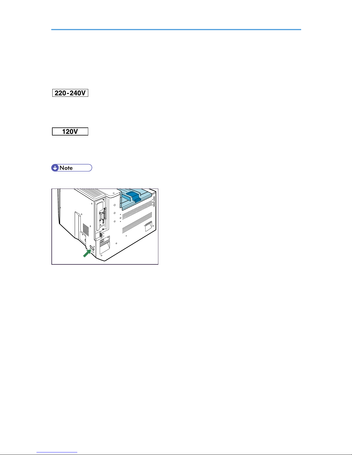
In this manual, the following symbols indicate information that relates to a specific printer model.
This indicates information about the 220 to 240 V model printer.
Read if you have purchased this model.
This indicates information about the 120 V model printer.
Read if you have purchased this model.
• Check the label on the rear of the printer to identify the printer's model.
BEK189S
9
Page 12

List of Options
This section provides a list of options for this printer, and how they are referred to as in this manual.
Option name Referred to as
HDD ENCRYPTION UNIT Type B HDD encryption unit
VM Card Type G VM card
Data Overwrite Security Unit Type J Data overwrite security unit
IEEE802.11a/g Interface Unit Type J,
IEEE802.11g Interface Unit Type K
Wireless LAN interface board
Data Storage Card Type A Data storage card
Memory Unit Type G 128 MB,
Memory Unit Type G 256 MB
SDRAM module
Hard Disk Drive Option Type 5000 Hard disk
Gigabit Ethernet Board Type A Gigabit Ethernet board
IEEE 1284 Interface Board Type A IEEE 1284 interface board
IPDS Unit Type 5100 IPDS unit
Finisher SR3030 2 tray finisher
Finisher SR790 1000-sheet finisher
Punch Unit Type 3260 NA 3/2,
Punch Unit Type 3260 EU 2/4,
Punch Unit Type 3260 SC
Punch unit
Output Jogger Unit Type 3260 Output jogger unit
Paper Feed Unit PB3040 1000-sheet paper feed unit
LCIT PB3050 2000-sheet paper feed unit
LCIT RT3000 1200-sheet paper feed unit
Bridge Unit BU3030 Bridge unit
10
Page 13

Installing the Operating Instructions
The CD-ROM "Manuals" provided with this printer contains HTML version Operating Instructions. Follow
the instructions below to install it.
• System Requirements:
• Windows 95/98/Me, Windows 2000/XP/Vista, Windows Server 2003/2003 R2, or
Windows NT 4.0
• 800 × 600 or higher monitor resolution
• Web Browsers:
• Microsoft Internet Explorer 4.01 SP2 or later
• Netscape 6.2 or later
• Non-recommended browsers can display the simplified manual only.
• HTML manuals can also be viewed on a Macintosh.
1. Quit all applications currently running.
2. Insert the CD-ROM “Manuals” into the CD-ROM drive.
The installer starts.
Auto Run may not work under certain operating system settings. In this case, launch "Setup.exe" in
the CD-ROM root directory.
3. Select an interface language, and click [OK].
4. Click [Install manuals].
If you want to read manuals from the CD-ROM, click [Read HTML manuals] or [Read PDF manuals].
5. Follow the instructions on the screen to complete the installation.
6. Click [Finish] when the installation is complete.
7. Click [Exit].
• If you cannot install a manual, copy the "MANUAL_HTML" folder to your computer's hard drive, and
then run "Setup.exe".
• To delete an installed manual, on the [Start] menu, click All Programs, then [Product Name], and then
uninstall the data.
• If you are installing the manuals on a Macintosh, open the "Manuals.htm" file on the CD-ROM.
11
Page 14

12
Page 15
1. Guide to the Printer
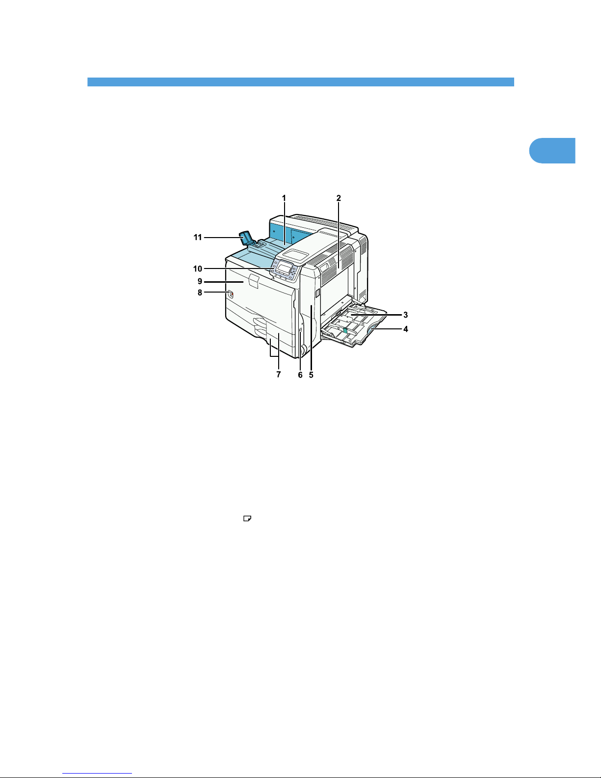
Exterior: Front View
This section explains names and functions of the parts on the front and right side of the printer.
BEK193S
1. Standard Output Tray
Printed pages are output here.
2. Upper Right Cover
Open this cover to remove jammed paper.
3. Bypass Tray
Up to 100 sheets of plain paper can be loaded.
4. Bypass Tray Extension
When loading paper larger than A4 , pull out the bypass tray extension.
5. Right Cover
Open this cover to remove jammed paper, or to replace Maintenance Kit B (the fusing unit and transfer unit).
6. Handle
Pull out this handle when lifting the printer.
7. Tray 1, Tray 2
Up to 550 sheets of plain paper can be loaded in each tray.
8. Power Switch
Use this switch to turn the power on and off.
9. Front Cover
Open this cover to replace the toner or Maintenance Kit A (the development unit).
13
1
Page 16

10. Control Panel
Contains keys for printer control and a display that shows the printer's status.
11. Paper Support
Extend the paper support when printing to paper larger than A3 .
1. Guide to the Printer
14
1
Page 17
Exterior: Rear View
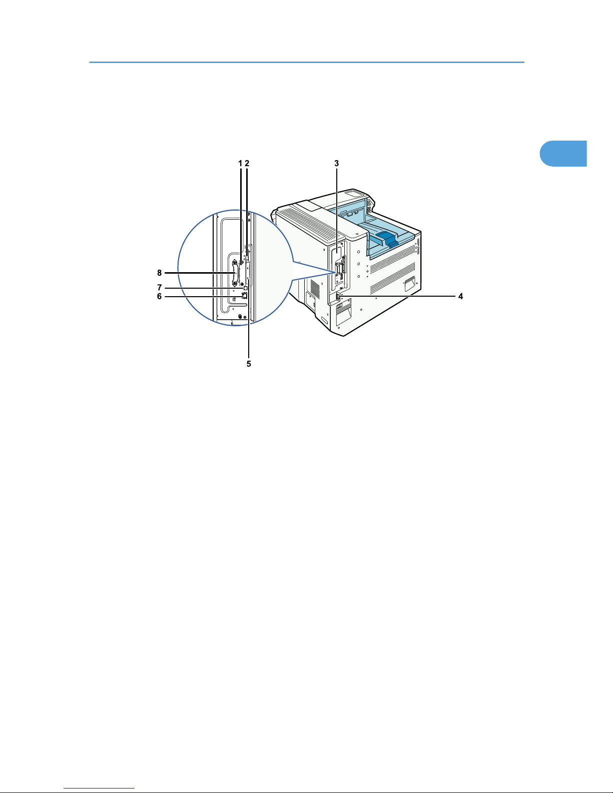
This section explains names and functions of the parts on the rear side of the printer.
BEK133S
1. Optional Interface Board Slot
Install an optional interface board. The Gigabit Ethernet board, Wireless LAN board, or IEEE1284 interface
board can be installed.
2. USB Port A
This port is usually not used.
3. Controller Board
Slide this out to install the hard disk or SDRAM module.
4. Power Connector
Connect the power cord to the printer. Insert the other end of the cable into an electrical outlet.
5. SD Card Slots
Remove the cover and install the SD cards. Install the data overwrite security unit, data storage card, or IPDS
unit in the upper slot. Install the HDD encryption unit or VM card in the lower slot.
6. Ethernet Port
Use a network interface cable to connect the printer to the network.
7. USB Port B
Use a USB cable to connect the printer to a computer.
8. Handle
Hold this handle when you pull out the controller board.
Exterior: Rear View
15
1
Page 18
Interior
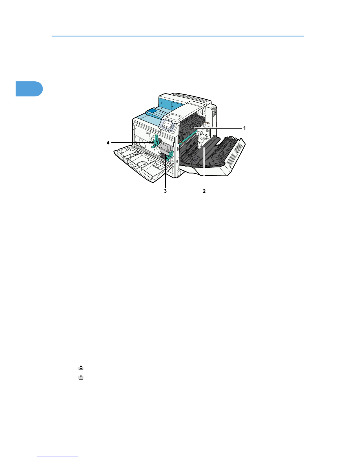
This section explains names and functions of the parts inside of the printer.
BEK002S
1. Fusing Unit
Replace the fusing unit when the following messages appear:
• "Replace Maint. Kit B soon."/ "A new kit is required."/ "Contact your local vendor."
• "Replace Maintenance Kit B."
The fusing unit is included in Maintenance Kit B.
2. Transfer Unit
Replace the transfer unit when the following messages appear:
• "Replace Maint. Kit B soon."/"A new kit is required."/ "Contact your local vendor."
• "Replace Maintenance Kit B."
The transfer unit is included in Maintenance Kit B.
3. Development Unit
Replace the development unit when the following messages appear:
• "Replace Maint. Kit A soon."/ "A new kit is required."/ "Contact your local vendor."
• "Replace Maintenance Kit A."
The development unit is included in Maintenance Kit A.
4. Toner
Replace the toner when the following messages appear:
• " Toner is almost empty."/ "Contact your local vendor."
• " Add toner"
1. Guide to the Printer
16
1
Page 19
Control Panel
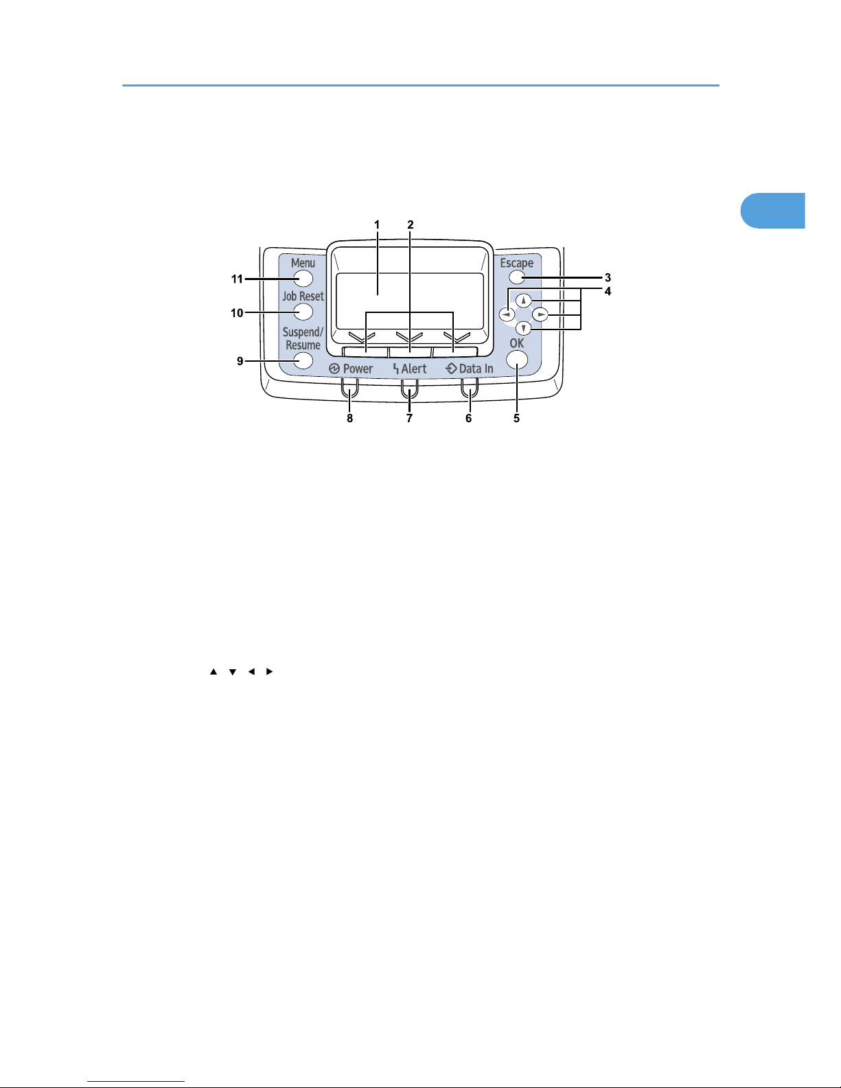
This section explains names and usage of the parts of the control panel.
BEK202S
1. Display
Displays current printer status and error messages.
Entering energy saver mode turns off the back light. For details about energy saver mode, see Software Guide.
2. Selection Keys
Correspond to the function items shown on the bottom line of the display.
3. [Escape] Key
Press this key to return to the previous display.
4. Scroll Keys
Press to move the cursor in each direction.
When the [ ] [ ] [ ] [ ] keys appear in this manual, press the scroll key of the same direction.
5. [OK] Key
Press this key to confirm settings or setting values, or move to the next menu level.
6. Data In indicator
Blinks when the printer is receiving data from a computer. Lights up if there is data to be printed.
7. Alert Indicator
Lights up in red or yellow when a printer error occurs.
Red: printing is not possible/possible but print quality cannot be ensured.
Yellow: printer requires maintenance, such as replacing consumables, shortly.
Follow the instructions that appear on the display.
8. Power Indicator
Remains lit while the power is on. It is unlit when the power is off or while the printer is in energy saver mode.
Control Panel
17
1
Page 20

9. [Suspend/Resume] Key
Press this key to suspend a print job. The key lights up while the job is suspended. To resume the job, press this
key again.
10. [Job Reset] Key
Press this key to cancel an ongoing print job.
11. [Menu] Key
Press this key to configure and check the current printer settings.
While configuring settings, press this key to return to the initial screen.
1. Guide to the Printer
18
1
Page 21
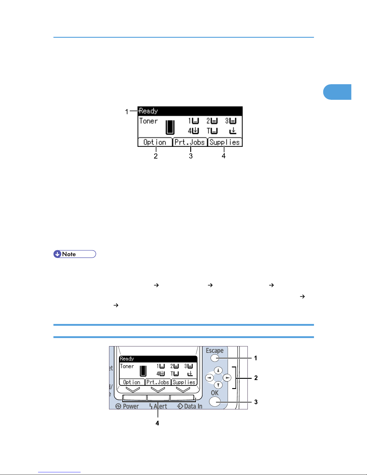
Display Panel
The display panel shows machine status, error messages, and function menus.
The items are highlighted when selected.
BEK302S
1. Operational Status or Messages
Displays the current printer status or messages.
2. [Option]
Press to display the status of options installed in the printer.
3. [Prt.Jobs]
Press to display print jobs sent from a computer. For details, see Software Guide.
4. [Supplies]
Press to display the menu of supplies for the printer.
• [Prt.Jobs] is displayed only when the hard disk is installed in the printer.
• By default, the remaining amount of toner and paper in each tray are displayed. You can change this
setting by selecting [Maintenance] [General Settings] [Display Supply Info] [Off].
• Adjust the brightness if the screen is dark. To adjust the display contrast, select [Maintenance]
[General Settings] [Display Contrast].
Reading the Display and Using Keys
BEK203S
Display Panel
19
1
Page 22

1. [Escape] key
Cancels an operation or returns to the previous display.
2. Scroll keys
Move the cursor in each direction.
When the [ ] [ ] [ ] [ ] keys appear in this manual, press the scroll key of the same direction.
3. [OK] key
Confirms settings or setting values, or moves to the next menu level.
4. Selection keys
Correspond to the function items shown on the bottom line of the display.
When this manual instructs you to "press [Option]", press the left selection key.
1. Guide to the Printer
20
1
Page 23

2. Installing Options
Available Options
By installing options, you can improve printer performance and expand the available features.
• Before installing options, the machine should be turned off and unplugged for at least an hour.
Components inside the machine become very hot, and can cause a burn if touched.
Order of Option Installation
When installing multiple options, the following order is recommended:
1. Attach the 1000-sheet paper feed unit or 2000-sheet paper feed unit
Either the 1000-sheet paper feed unit or 2000-sheet paper feed unit can be attached, but not both.
2. Attach the 1200-sheet paper feed unit
The 1000-sheet paper feed unit or 2000-sheet paper feed unit must have been attached.
To attach this option, contact your sales or service representative.
3. Install the SDRAM module
Install in the slot inside the controller board.
4. Install the hard disk
Install inside the controller board.
5. Install the interface board
Install in the slot of the controller board.
Only one interface board can be installed.
6. Insert SD card options
Insert in the SD card slot of the controller board.
There are two slots for SD cards.
Each slot supports different types of SD cards.
If you want to use two or more SD cards that can be inserted in the same slot, contact your sales or
service representative.
7. Attach the bridge unit
To attach this option, contact your sales or service representative.
8. Attach the 1000-sheet finisher or 2 tray finisher
Either the 1000-sheet finisher or 2 tray finisher can be attached, but not both.
21
2
Page 24
The bridge unit and the 1000-sheet paper feed unit or 2000-sheet paper feed unit must have been
attached.
To attach this option, contact your sales or service representative.
9. Install the punch unit in the 2 tray finisher
To attach this option, contact your sales or service representative.
10. Attach the output jogger unit to the 2 tray finisher
To attach this option, contact your sales or service representative.
Where to Install Options
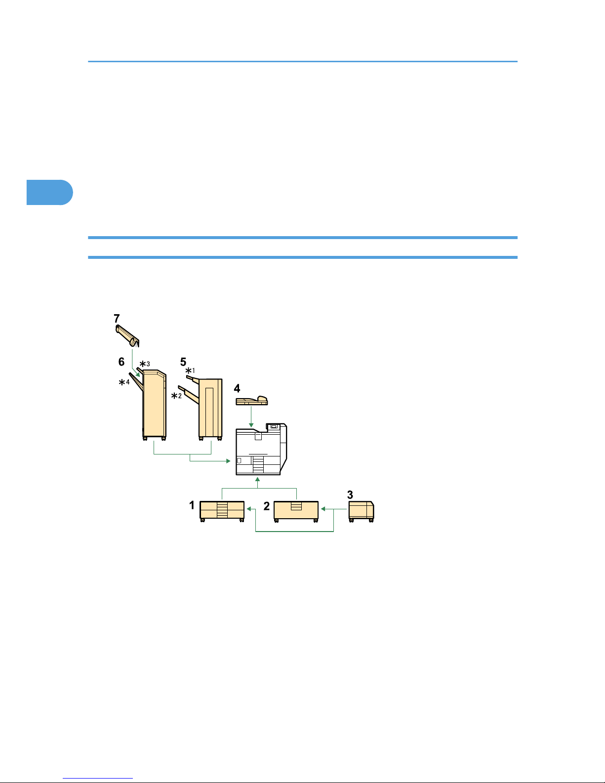
Install options in the locations shown in the following illustrations.
External options
BEK188S
1. 1000-sheet paper feed unit
Attach to the underside of the printer. See “Attaching the Paper Fed Unit”.
2. 2000-sheet paper feed unit
Attach to the underside of the printer. See “Attaching the Paper Fed Unit”.
3. 1200-sheet paper feed unit
Attach to the right side of the 1000-sheet paper feed unit or 2000-sheet paper feed unit.
To attach this option, contact your sales or service representative.
4. Bridge unit
Remove the output tray and attach the bridge unit.
2. Installing Options
22
2
Page 25
To attach this option, contact your sales or service representative.
5. 1000-sheet finisher
Attach to the left side of the printer.
• *1: Finisher upper tray
• *2: Finisher shift tray
To attach this option, contact your sales or service representative.
6. 2 Tray finisher
Attach to the left side of the printer.
• *3: Finisher upper tray
• *4: Finisher shift tray
To attach this option, contact your sales or service representative.
7. Output jogger unit
Attach to the 2 tray finisher.
To attach this option, contact your sales or service representative.
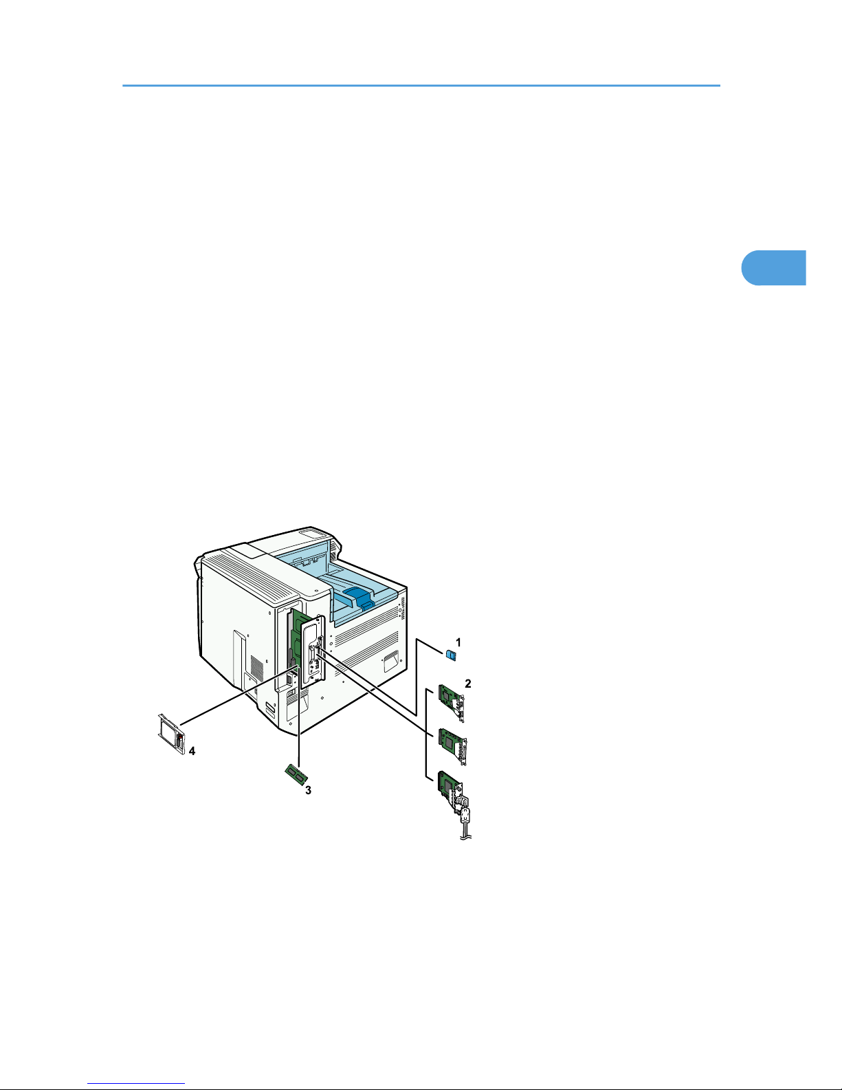
Internal options
BEK186S
1. Data overwrite security unit/data storage card/IPDS unit/HDD encryption unit
If you want to use two or more SD cards that can be inserted in the same slot, contact your sales
or service representative.
• Upper slot: data overwrite security unit, data storage card, or IPDS unit
Available Options
23
2
Page 26

• Lower slot: HDD encryption unit or VM card
See “Installing SD Card Options”.
2. Optional interface board
Only one interface board can be installed.
• Gigabit Ethernet board
• IEEE 1284 interface board
• IEEE 802.11 g interface board
• IEEE 802.11 a/g interface board
See “Installing the Interface Units”.
3. SDRAM module
See "Installing the Memory Expansion Units".
4. Hard disk
See "Installing the Memory Expansion Units".
• For the specifications of each option, see "Specifications".
• p.26 "Attaching the Paper Feed Unit"
• p.46 "Installing SD Card Options"
• p.37 "Installing the Interface Units"
• p.30 "Installing the Memory Expansion Units"
• p.206 "Specifications"
Cautions When Re-installing the Controller Board
When installing options inside the controller board, handle the board carefully while it is outside the printer.
To re-install the controller board, holding the handle in the center of the board, push the board firmly into
the printer.
• The following may occur if the controller board is not correctly installed:
1. All control panel indicators are lit.
2. No control panel indicators are lit.
3. The "SC670" error message appears on the display.
2. Installing Options
24
2
Page 27

BEK156S
Available Options
25
2
Page 28
Attaching the Paper Feed Unit
This section describes how to attach the 1000-sheet paper feed unit or 2000-sheet paper feed unit to the
printer. The procedure is the same for both units. The 1000-sheet paper feed unit is used as an example.
• The printer weights approximately 73 kg (161 lb.).
• Four or more people are required to move the printer. Hold the handles located on both sides, and
then lift it slowly. Lifting it carelessly or dropping it may cause an injury.
• It is dangerous to handle the plug with wet hands. Doing this may result in receiving an electric shock.
• Before moving the machine, unplug the power cord from the outlet. If the cord is unplugged abruptly,
it could become damaged. Damaged plugs or cords can cause an electrical or fire hazard.
• When attaching multiple options, attach the paper feed unit first.
• Either the 1000-sheet paper feed unit or 2000-sheet paper feed unit can be attached, but not both.
• When the 1000-sheet paper feed unit or the 2000-sheet paper feed unit is attached, you can also
attach the 1200-sheet paper feed unit. To attach the 1200-sheet paper feed unit, contact your sales
or service representative.
• Before using the new paper feed unit, you must configure settings in the printer driver.
1. Check the contents of the package.
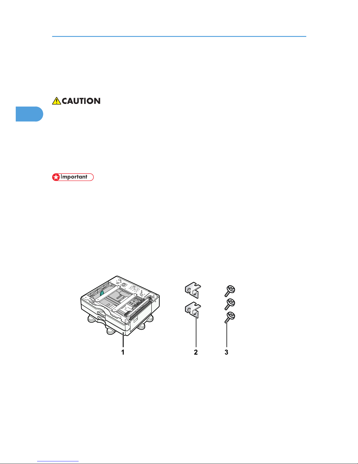
• For 1000-sheet paper feed unit:
BEK242S
1. 1000-sheet paper feed unit
2. Two Brackets
3. Three Screws
• For 2000-sheet paper feed unit:
2. Installing Options
26
2
Page 29
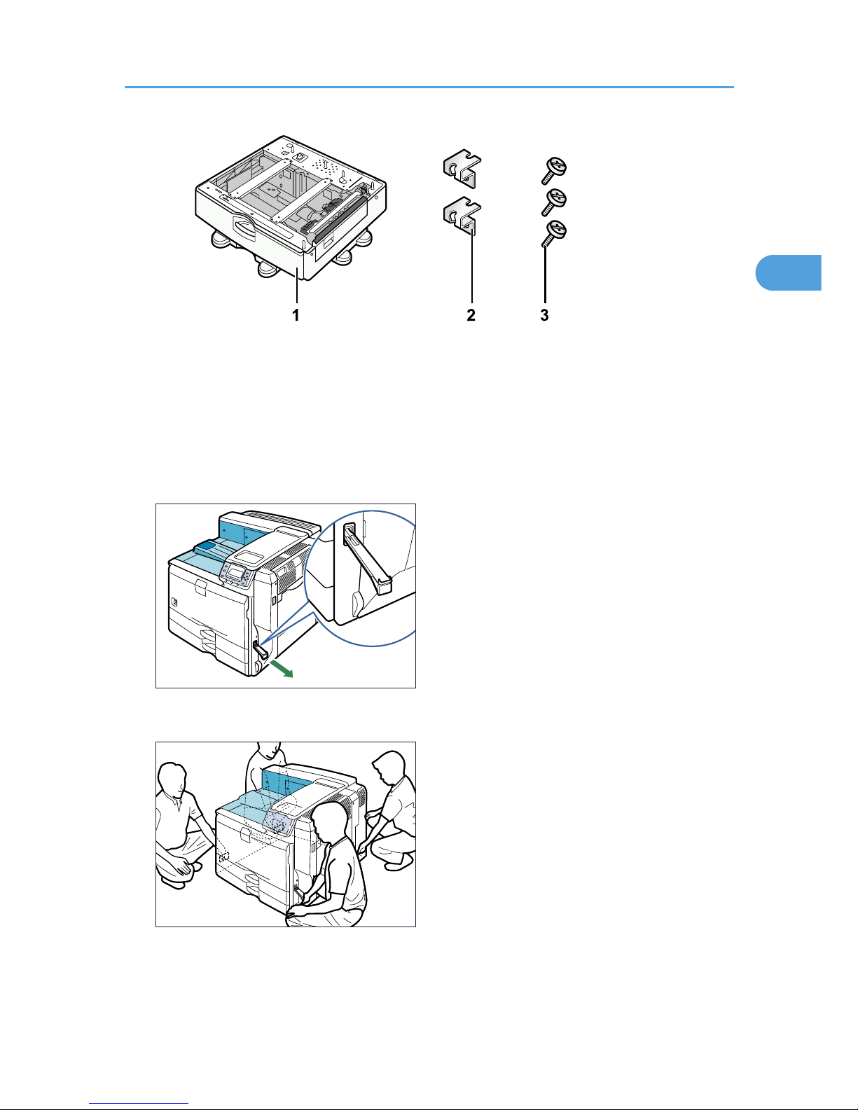
BEK241S
1. 2000-sheet paper feed unit
2. Two Brackets
3. Three Screws
2. Turn the printer off and unplug the power cord.
3. Remove the packaging from the paper feed unit.
4. Pull out the handle from the right side of the printer.
BEK011S
5. Lift the printer using the handles on both sides.
BEK012S
The printer should always be lifted by at least four people.
Attaching the Paper Feed Unit
27
2
Page 30
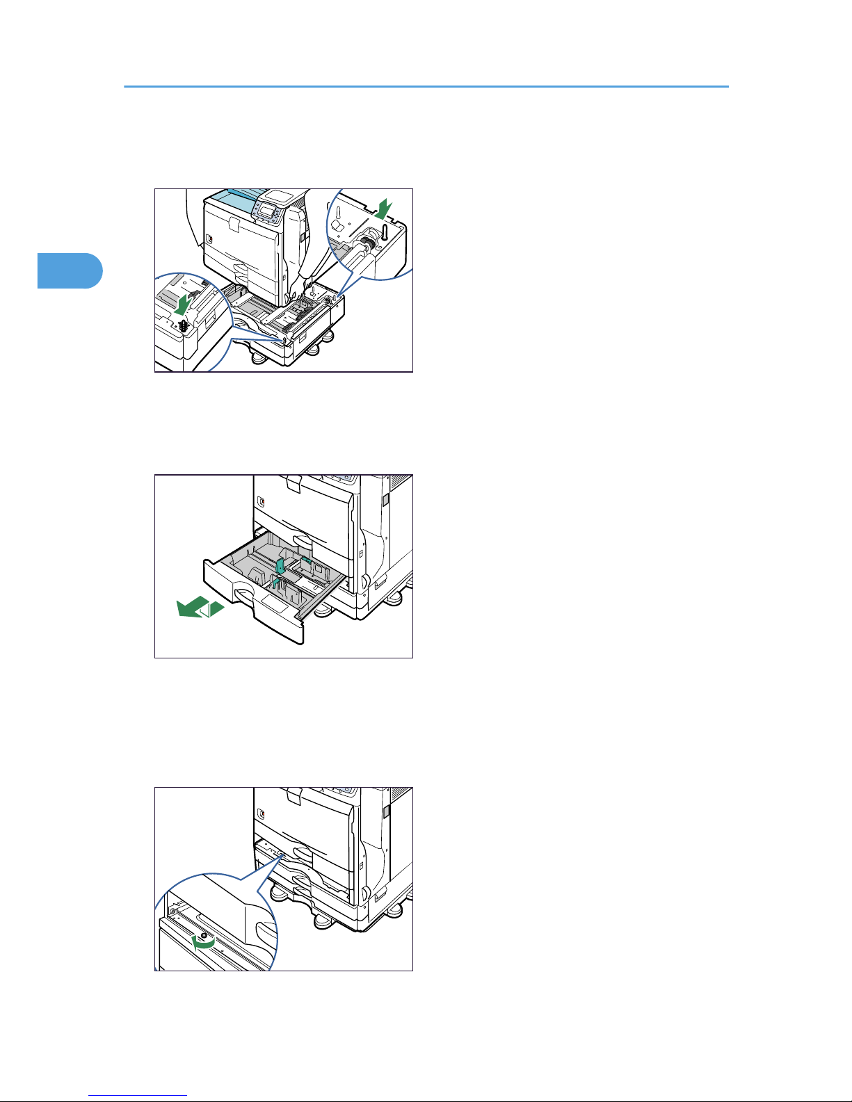
6. Align the front of the printer with the front of the paper feed unit, and slowly lower it.
Place it so that it is held firmly in place by the vertical pins.
BEK102S
Return the handle you pulled out from the printer to its original position.
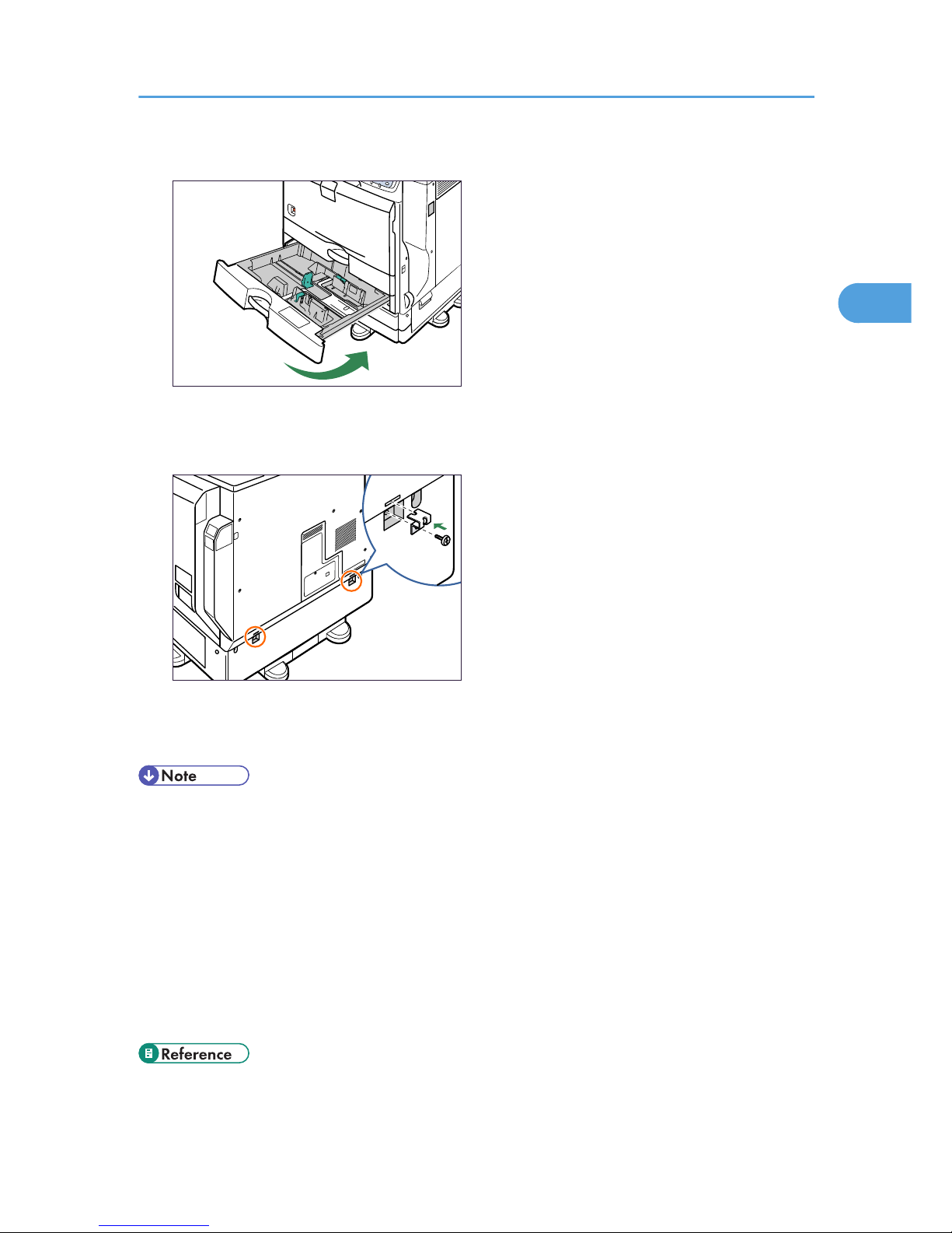
7. Pull out tray 2 of the printer slowly until it stops, lift the front of the tray slightly, and then
pull out the tray completely.
BEK103S
Place the tray on a flat surface.
8. Attach a screw in the hole on the left side of the tray opening to secure the printer to the
paper feed unit.
Tighten the screw firmly using a coin.
BEK104S
2. Installing Options
28
2
Page 31
9. Lift the front of the tray, and slide it carefully into the printer until it stops.
BEK105S
10. On the rear of the unit, attach two brackets using the remaining screws.
Tighten the screws firmly using a coin.
BEK106S
11. Plug in the power cord, and then turn on the printer.
12. Print the configuration page to confirm that the unit was attached correctly.
• To confirm whether the optional paper feed unit was correctly attached, print the configuration page,
and check "Attached Equipment" on the configuration page. If the unit was attached correctly, the
following will be displayed:
• 1000-sheet paper feed unit: Lower Paper Trays
• 2000-sheet paper feed unit: Tray 3
• If the optional paper feed unit was not installed properly, repeat the procedure from step 2. If it cannot
be installed correctly even after reattempting installation, contact your sales or service representative.
• If the print area is not centered correctly, see "Adjusting Printing Position".
• For information about printing the configuration page, see "Test Printing", Quick Installation Guide.
• p.147 "Adjusting Printing Position"
Attaching the Paper Feed Unit
29
2
Page 32
Installing the Memory Expansion Units
This section describes how to install the memory expansion units.
Installing the SDRAM Module
• Do not touch the inside of the controller board compartment. It may cause a machine malfunction or
a burn.
• Before beginning work, ground yourself by touching something metal to discharge any static
electricity. Static electricity can damage the SDRAM module.
• Do not subject the SDRAM module to physical shocks.
• When installing the SDRAM module, hard disk, and wireless LAN interface board together, install
them in the following order: SDRAM module, hard disk, wireless LAN interface board. If the hard disk
or wireless LAN interface board is already installed, remove it before installing the SDRAM module.
• The printer comes equipped with 256 MB of memory. This can be expanded to a maximum of 512
MB.
• Before using the new SDRAM module, you must configure settings in the printer driver.
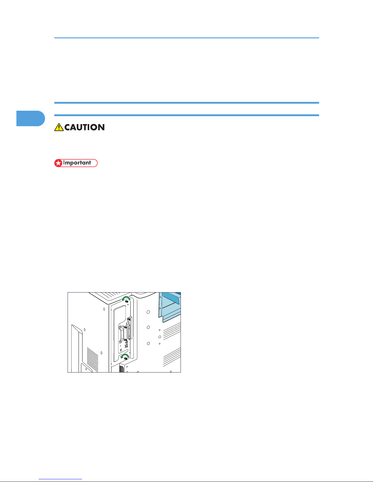
1. Turn the printer off and unplug the power cord.
2. Remove the two screws securing the controller board.
BEK134S
The removed screws will be used to secure the controller board again later.
3. Holding the handle, carefully pull out the controller board.
Slide the controller board completely out and place it on a flat surface such as a table.
2. Installing Options
30
2
Page 33
BEK135S
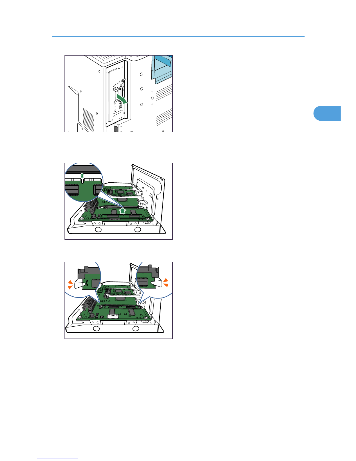
4. Align the notch on the SDRAM module with the slot, and then carefully push in the SDRAM
module at an angle.
BEK138S
5. Holding the SDRAM module at an angle, press it down until it clicks into place.
BEK139S
6. When also installing the hard disk, install it before returning the controller board to the
printer.
Installing the Memory Expansion Units
31
2
Page 34
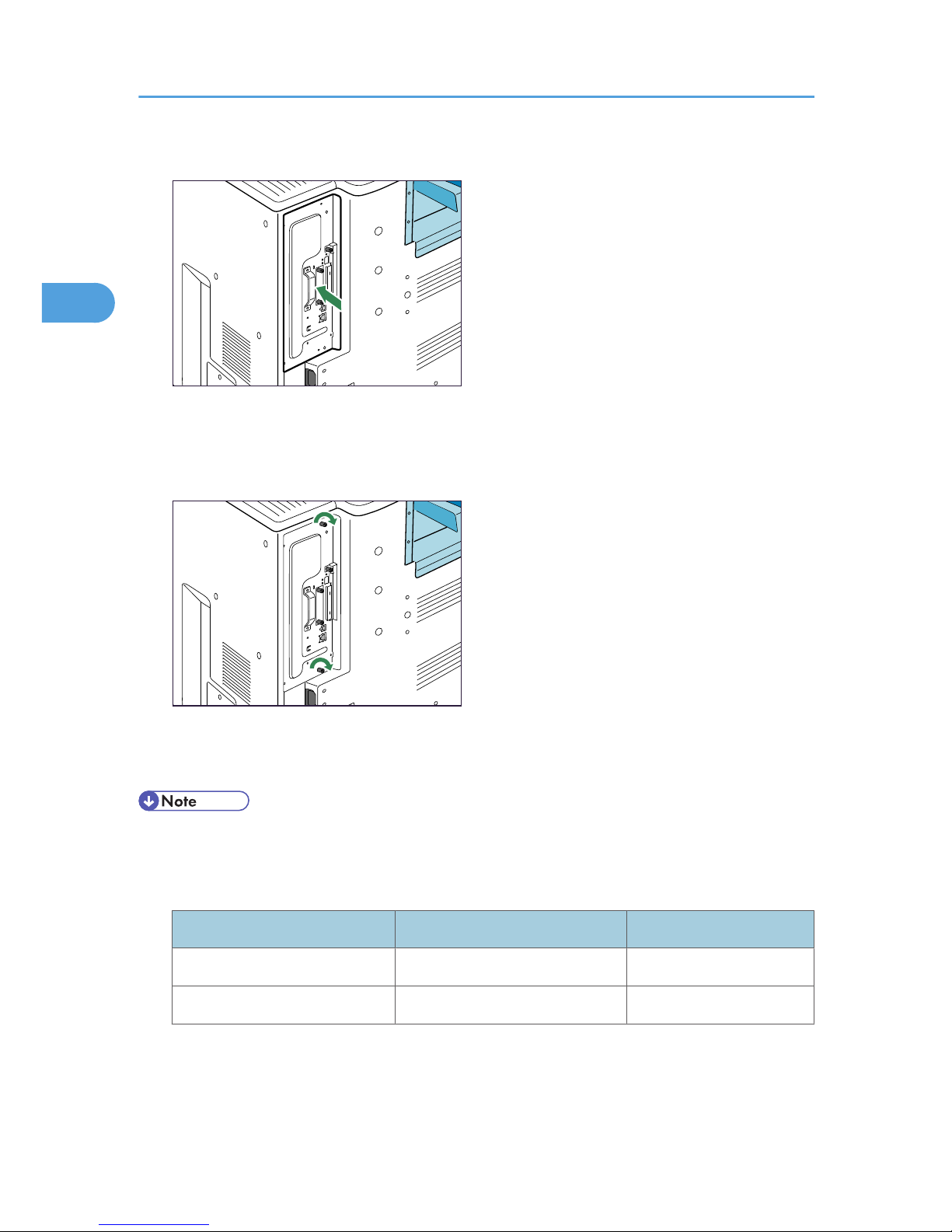
7. Fit the controller board into the printer, and push it carefully in until it stops.
BEK140S
Push it firmly into the printer using the handle. The printer may malfunction if the controller board is
not properly installed.
8. Fasten the controller board to the printer using the two screws.
BEK141S
9. Plug in the power cord, and then turn on the printer.
10. Print the configuration page to confirm that the SDRAM module was installed correctly.
• Confirm that the SDRAM module was correctly installed by printing the configuration page. Check
that the total memory value is shown in "Device Connection" on the configuration page.
• The table below shows the total SDRAM module capacities.
Standard Extended Total
256MB 128MB 384MB
256MB 256MB 512MB
• If the SDRAM module was not installed properly, repeat the procedure from the beginning. If it cannot
be installed correctly even after reattempting installation, contact your sales or service representative.
• For information on printing the configuration page, see "Test Printing", Quick Installation Guide.
2. Installing Options
32
2
Page 35
• Install the controller board carefully. For details, see "Cautions When Re-installing the Controller
Board".
• p.24 "Cautions When Re-installing the Controller Board"
Installing the Hard Disk
• Do not touch the inside of the controller board compartment. It may cause a machine malfunction or
a burn.
• Before beginning work, ground yourself by touching something metal to discharge any static
electricity. Static electricity can damage the hard disk.
• Do not subject the hard disk to physical shocks.
• When installing the SDRAM module, hard disk, and wireless LAN interface board together, install
them in the following order: SDRAM module, hard disk, wireless LAN board. If the wireless LAN
interface board is already installed, remove it before installing the hard disk.
• Install the hard disk carefully if the SDRAM module is already installed. If the hard disk comes in
contact with the SDRAM module, the SDRAM module may become damaged.
• Before using the new hard disk, you must configure settings in the printer driver.
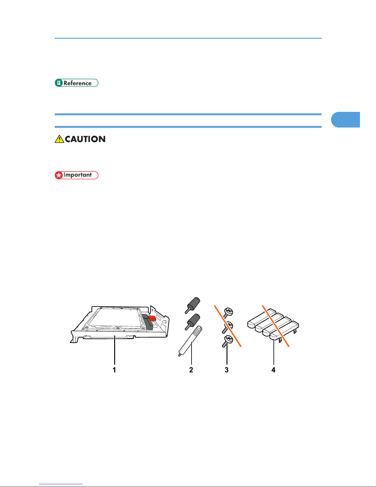
1. Check the contents of the package.
BEK199S
1. Hard Disk
2. Three Screws
3. Screws for Other Models
4. Key Tops
2. Turn the printer off and unplug the power cord.
Installing the Memory Expansion Units
33
2
Page 36
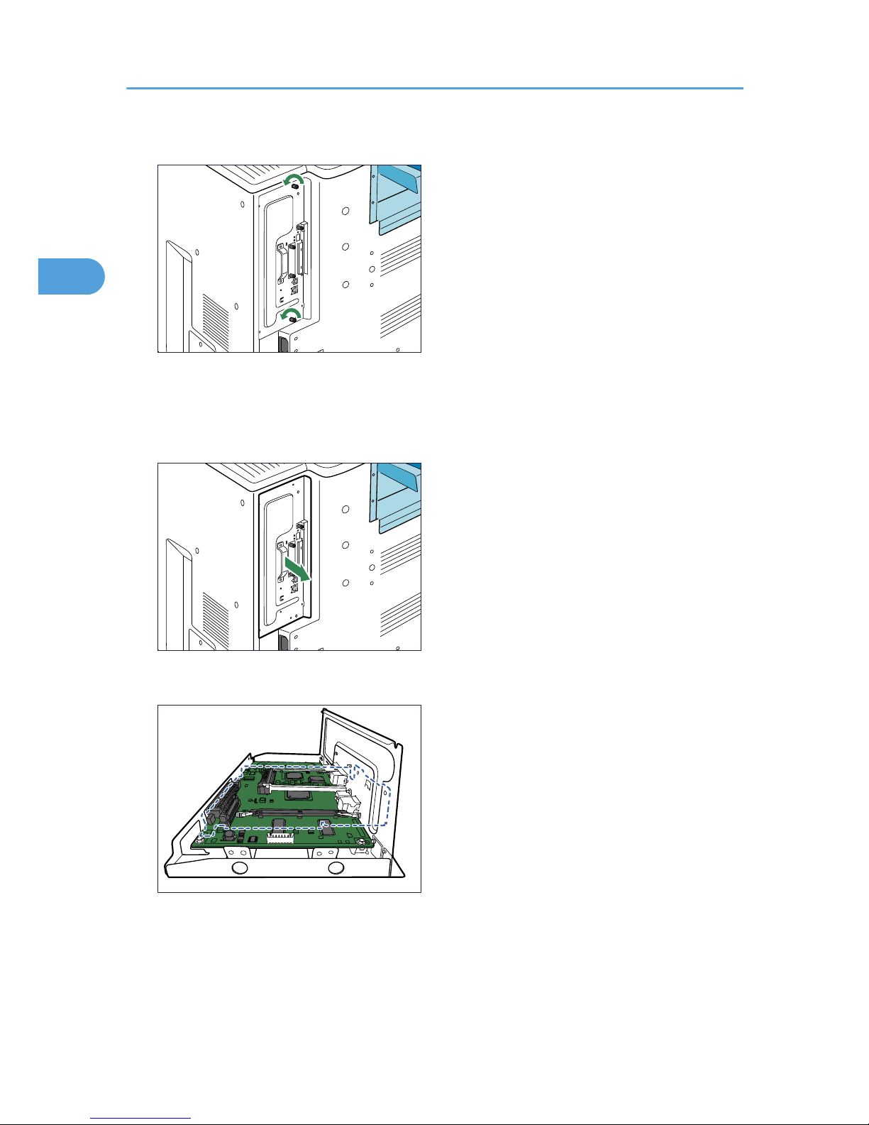
3. Remove the two screws securing the controller board.
BEK134S
The removed screws will be used to secure the controller board again later.
4. Holding the handle, carefully pull out the controller board.
Slide the controller board completely out and place it on a flat surface such as a table.
BEK135S
5. Install the hard disk in the indicated position.
BEK022S
Install the hard disk carefully if the SDRAM module is already installed. If the hard disk comes in
contact with the SDRAM module, the SDRAM module may become damaged.
2. Installing Options
34
2
Page 37
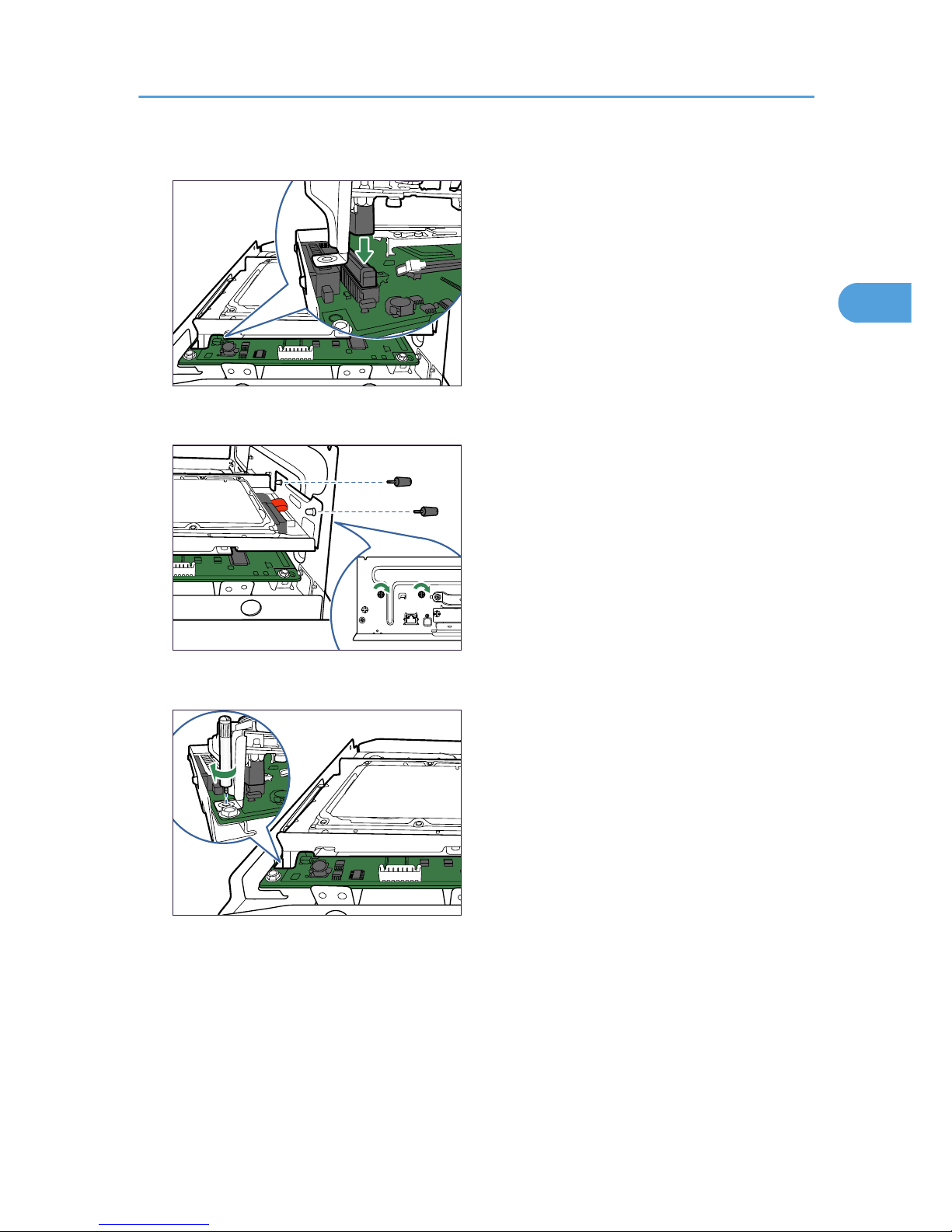
6. Fit the hard disk on the connector of the controller board carefully until it stops.
BEK023S
7. Fasten the two screws clockwise as shown by using a coin, to secure the hard disk.
BEK024S
8. Fasten the screw clockwise as shown by using a coin, to secure the hard disk.
BEK025S
Installing the Memory Expansion Units
35
2
Page 38
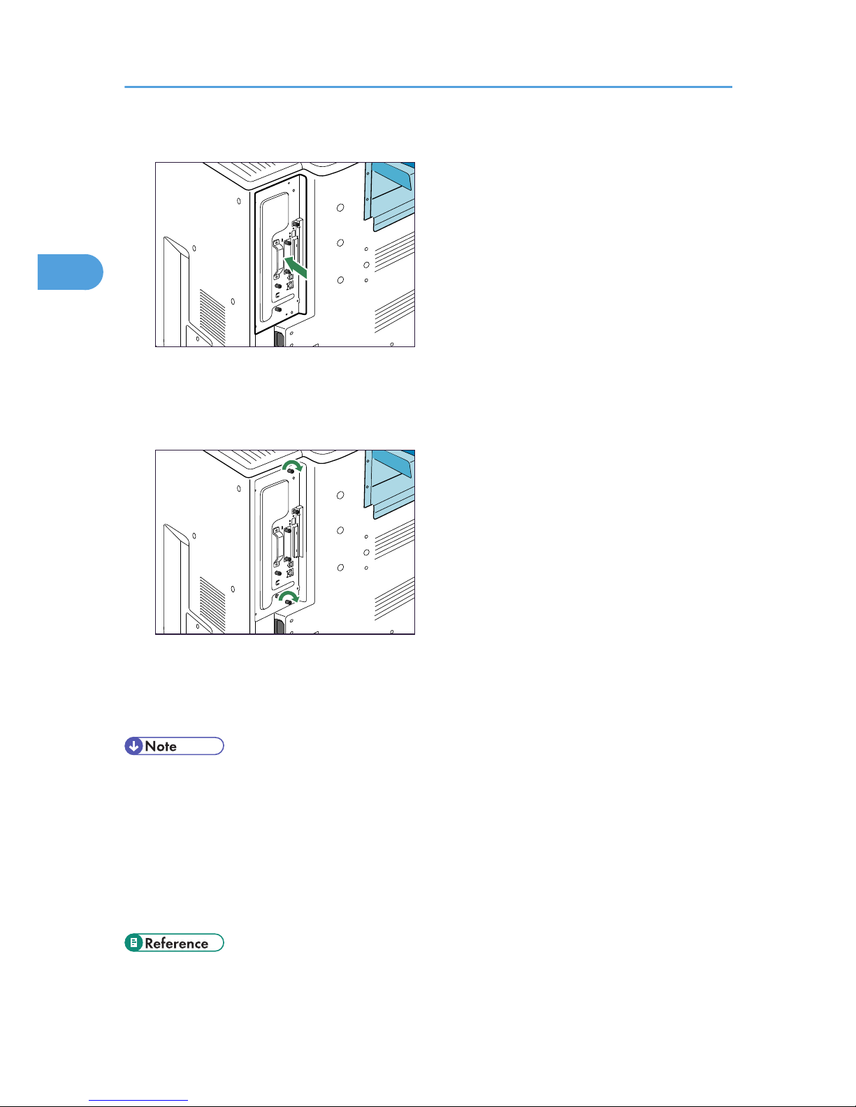
9. Fit the controller board into the printer, and push it carefully in until it stops.
BEK310S
Push it firmly into the printer using the handle. The printer may malfunction if the controller board is
not properly installed.
10. Fasten the controller board to the printer using the two screws.
BEK032S
11. Plug in the power cord, and then turn on the printer.
When the power is turned on, the hard disk will be formatted automatically.
12. Print the configuration page to confirm that the hard disk was installed correctly.
• Confirm that the hard disk was correctly installed by printing the configuration page. If it is correctly
installed, "Hard Disk Drive" will appear for "Device Connection" on the configuration page.
• If the hard disk was not installed properly, repeat the procedure from step 2. If it cannot be installed
correctly even after reattempting installation, contact your sales or service representative.
• For information on printing the configuration page, see "Test Printing", Quick Installation Guide.
• Install the controller board carefully. For details, see "Cautions When Re-installing the Controller
Board".
• p.24 "Cautions When Re-installing the Controller Board"
2. Installing Options
36
2
Page 39
Installing the Interface Units
Installing the Gigabit Ethernet Board
• Before beginning work, ground yourself by touching something metal to discharge any static
electricity. Static electricity can damage the board.
• Do not subject the board to physical shocks.
• The printer's Ethernet and USB ports are not available when the Gigabit Ethernet board is attached
to the printer. Use the Ethernet and USB ports on the Gigabit Ethernet board.
1. Check the contents of the package.
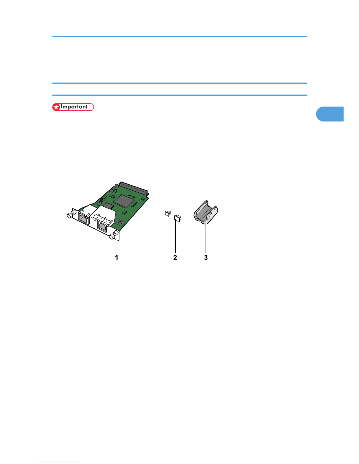
BEK240S
1. Gigabit Ethernet Board
2. Protective Caps (one each for the Ethernet port and the USB port)
3. Ferrite Core
Use the included ferrite core when connecting an Ethernet cable to the board.
2. Turn the printer off and unplug the power cord.
Installing the Interface Units
37
2
Page 40
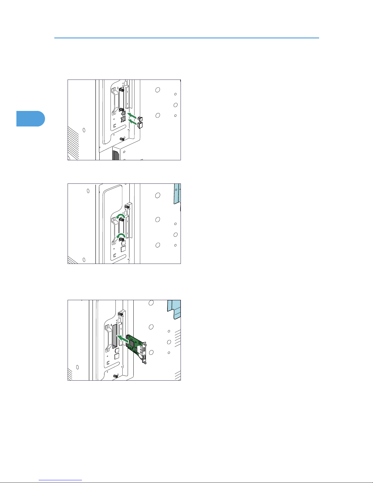
3. Unplug cables from the USB and Ethernet ports, and then cover them with the protective
caps.
BEK142S
4. Loosen the two screws and remove the slot cover.
BEK165S
The removed cover will not be reused.
5. Fully insert the Gigabit Ethernet board.
BEK143S
Confirm that the Gigabit Ethernet board is firmly connected to the controller board.
2. Installing Options
38
2
Page 41

6. Tighten the two screws to secure the board.
BEK249S
7. Plug in the power cord, and then turn on the printer.
8. Print the configuration page to confirm that the board was attached correctly.
• Confirm that the board was correctly installed by printing the configuration page. If it is correctly
installed, "Gigabit Ethernet Board" will appear for "Device Connection" on the configuration page.
• If the board was not installed properly, repeat the procedure from step 2. If it cannot be installed
correctly even after reattempting installation, contact your sales or service representative.
• For information on printing the configuration page, see "Test Printing", Quick Installation Guide.
• Before using the board, you must configure settings from the control panel. For details, see "Ethernet
Configuration".
• p.55 "Ethernet Configuration"
Installing the Wireless LAN Interface Board
• Before beginning work, ground yourself by touching something metal to discharge any static
electricity. Static electricity can damage the board.
• Do not subject the board to physical shocks.
• When installing the SDRAM module, hard disk, and wireless LAN interface board together, install
them in the following order: SDRAM module, hard disk, wireless LAN interface board. If the wireless
LAN interface board is already installed, remove it before installing the hard disk.
Installing the Interface Units
39
2
Page 42
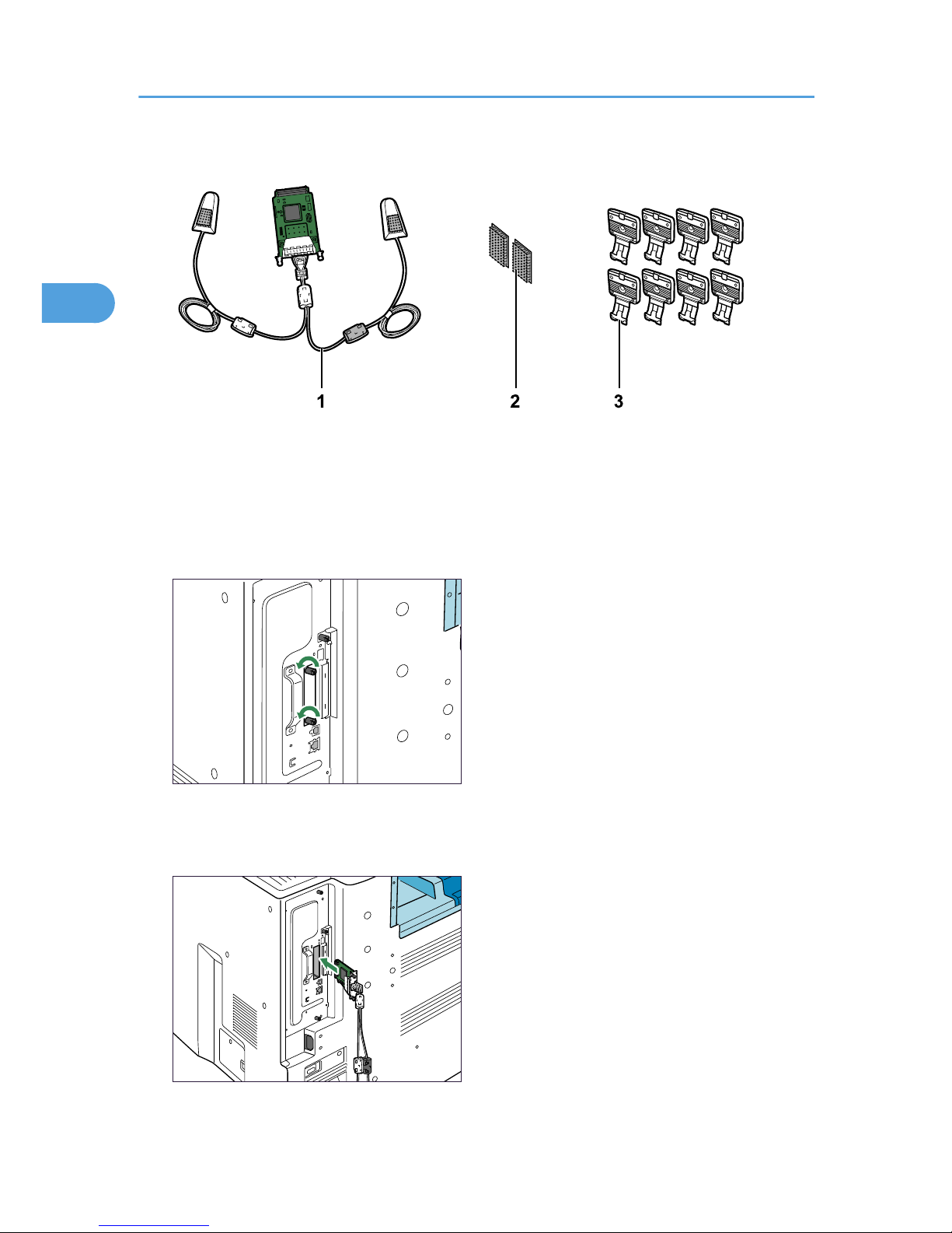
1. Check the contents of the package.
BEK175S
1. Wireless LAN Interface Board
2. Two Hook-and-loop Fasteners
3. Eight Hooks
2. Turn the printer off and unplug the power cord.
3. Loosen the two screws and remove the slot cover.
BEK145S
The removed cover will not be reused.
4. Fully insert the interface board.
BEK167S
2. Installing Options
40
2
Page 43
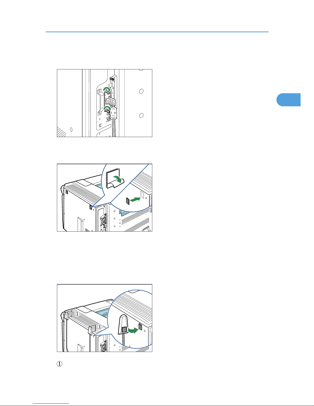
Confirm that the interface board is firmly connected to the controller board.
5. Tighten the two screws to secure the interface board.
BEK168S
6. Remove protective paper from the hook-and-loop fasteners, and then place them as far
away from each other as possible on the upper side of the printer rear.
BEK169S
Make sure that the hook-and-loop fasteners are not placed over any screw holes or seams on the
printer body.
7. Remove protective paper from antennas, and then attach the antennas upright to the hook-
and-loop fasteners. Attach the antenna coming from a black ferrite core on the right side of
the printer rear.
BEK170S
: The antenna tops must project at least 4 cm (1.6inches) above the printer body.
Installing the Interface Units
41
2
Page 44
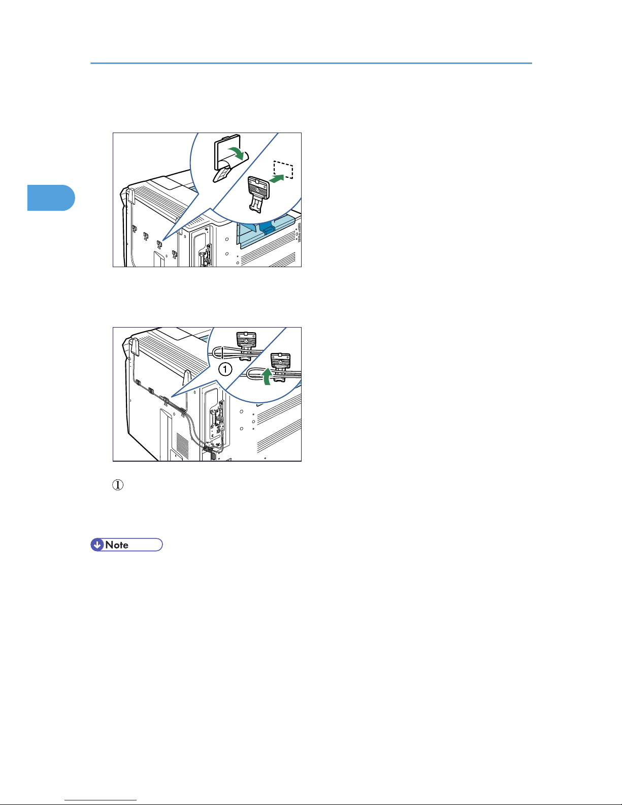
8. Remove protective paper from four hooks, and then attach the hooks evenly above the
concave area on the printer rear.
BEK171S
Extra hooks are spare accessories.
9. Secure the cables using the four hooks. Loop the cable for the antenna on the right as shown.
BEK172S
: The loop must have a diameter of at least 1 cm (0.4inches).
10. Plug in the power cord, and then turn on the printer.
11. Print the configuration page to confirm that the board was attached correctly.
• Confirm that the board was correctly installed by printing the configuration page. If it is correctly
installed, "Wireless LAN" will appear for "Device Connection" on the configuration page.
• If the board was not installed properly, repeat the procedure from step 2. If it cannot be installed
correctly even after reattempting installation, contact your sales or service representative.
• For information on printing the configuration page, see "Test Printing", Quick Installation Guide.
• If you need to open the hook, hold the tab of the hook, raise it slightly upward, and then pull it open.
2. Installing Options
42
2
Page 45
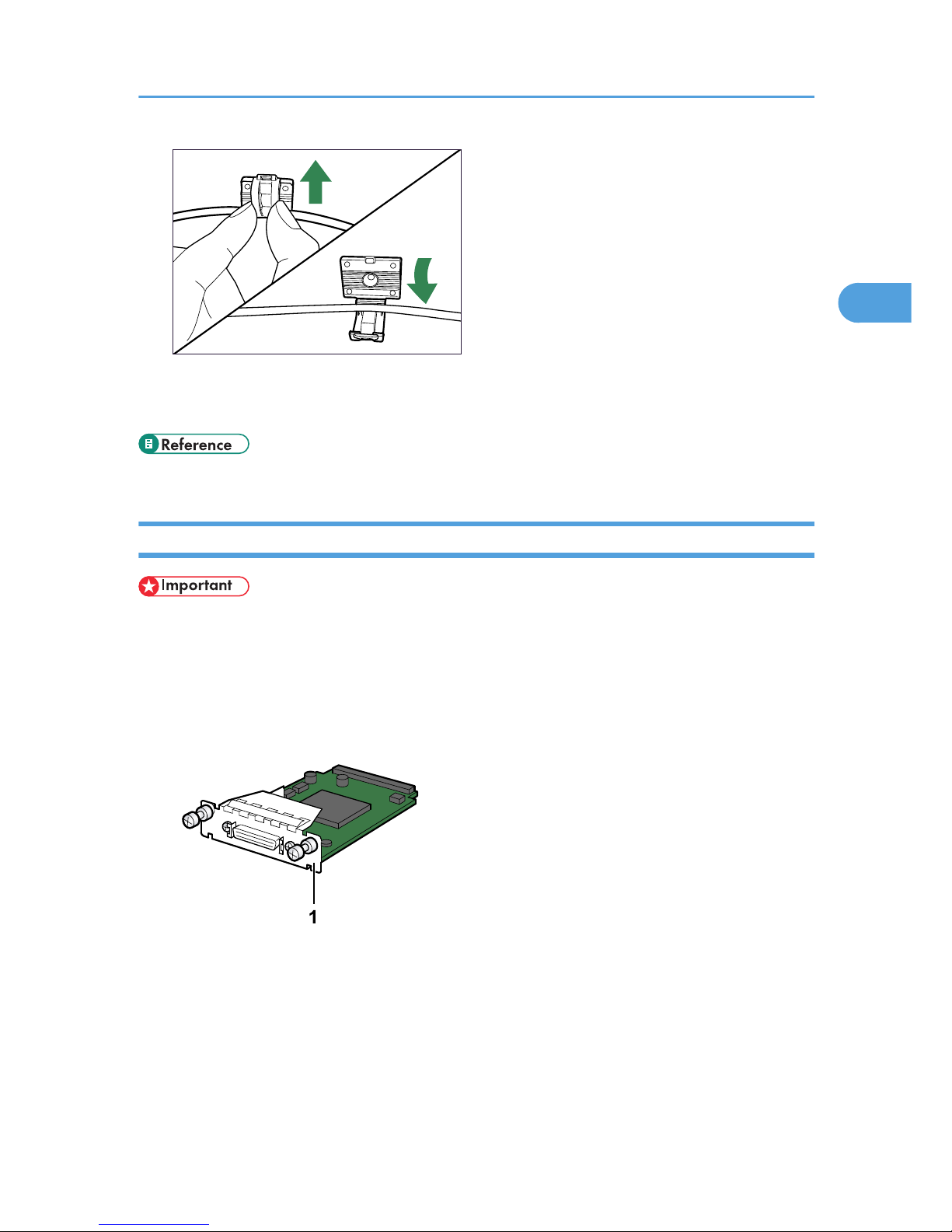
BEK173S
• Before using the board, you must configure settings from the printer control panel. For details, see
"Wireless LAN Configuration".
• p.64 "Wireless LAN Configuration"
Installing the IEEE 1284 Interface Board
• Before beginning work, ground yourself by touching something metal to discharge any static
electricity. Static electricity can damage the board.
• Do not subject the board to physical shocks.
• For connection to the IEEE 1284 interface board, use a half pitch 36-pin interface cable.
1. Check the contents of the package.
BEK224S
1. IEEE 1284 Interface Board
2. Turn the printer off and unplug the power cord.
Installing the Interface Units
43
2
Page 46
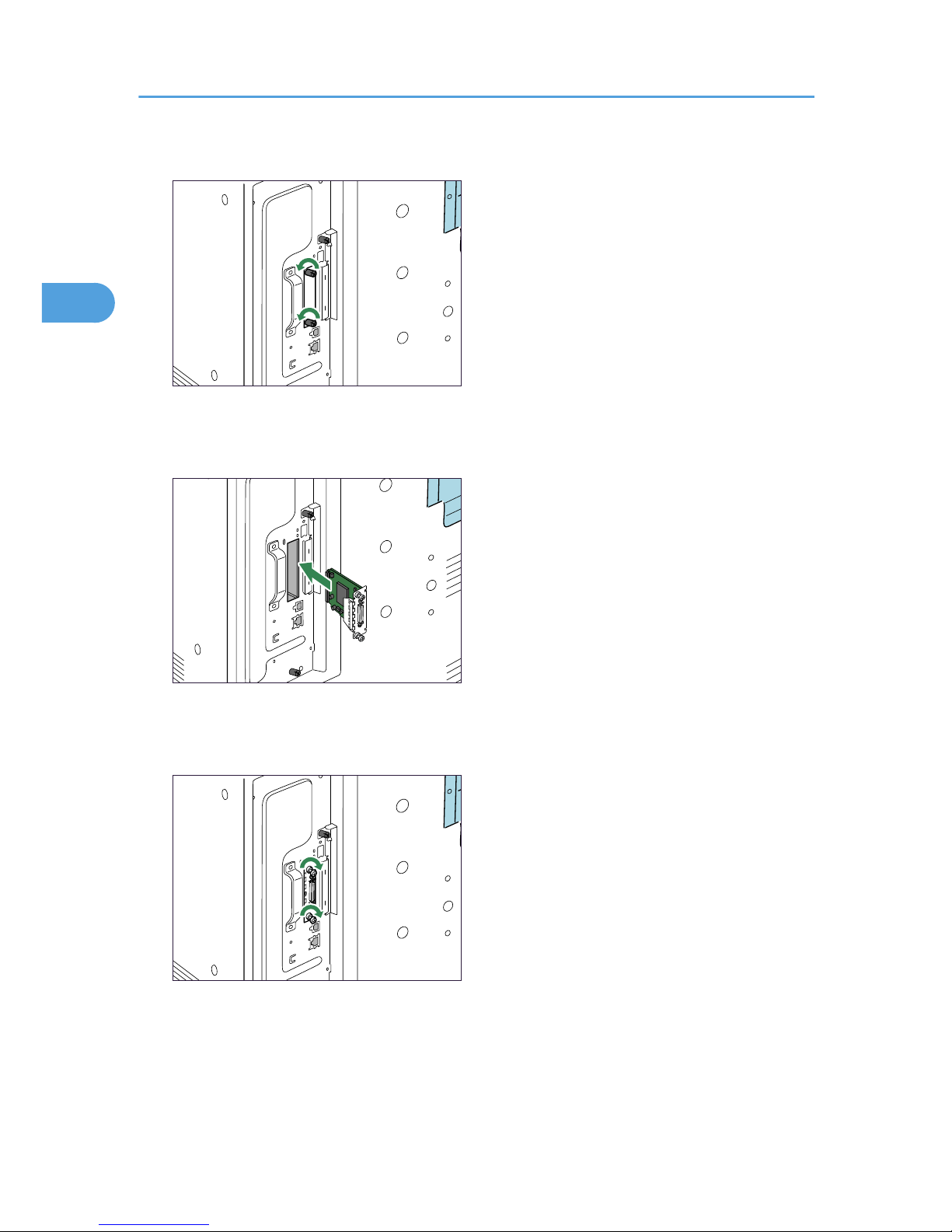
3. Loosen the two screws and remove the slot cover.
BEK145S
The removed cover will not be reused.
4. Fully insert the IEEE 1284 interface board.
BEK146S
Confirm that the IEEE 1284 interface board is firmly connected to the controller board.
5. Tighten the two screws to secure the interface board.
BEK147S
6. Plug in the power cord, and then turn on the printer.
7. Print the configuration page to confirm that the board was attached correctly.
2. Installing Options
44
2
Page 47

• Confirm that the board was correctly installed by printing the configuration page. If it is correctly
installed, "Parallel Interface" will appear for "Device Connection" on the configuration page.
• If the board was not installed properly, repeat the procedure from step 2. If it cannot be installed
correctly even after reattempting installation, contact your sales or service representative.
• For information on printing the configuration page, see "Test Printing", Quick Installation Guide.
• p.54 "Parallel Cable Connection"
Installing the Interface Units
45
2
Page 48
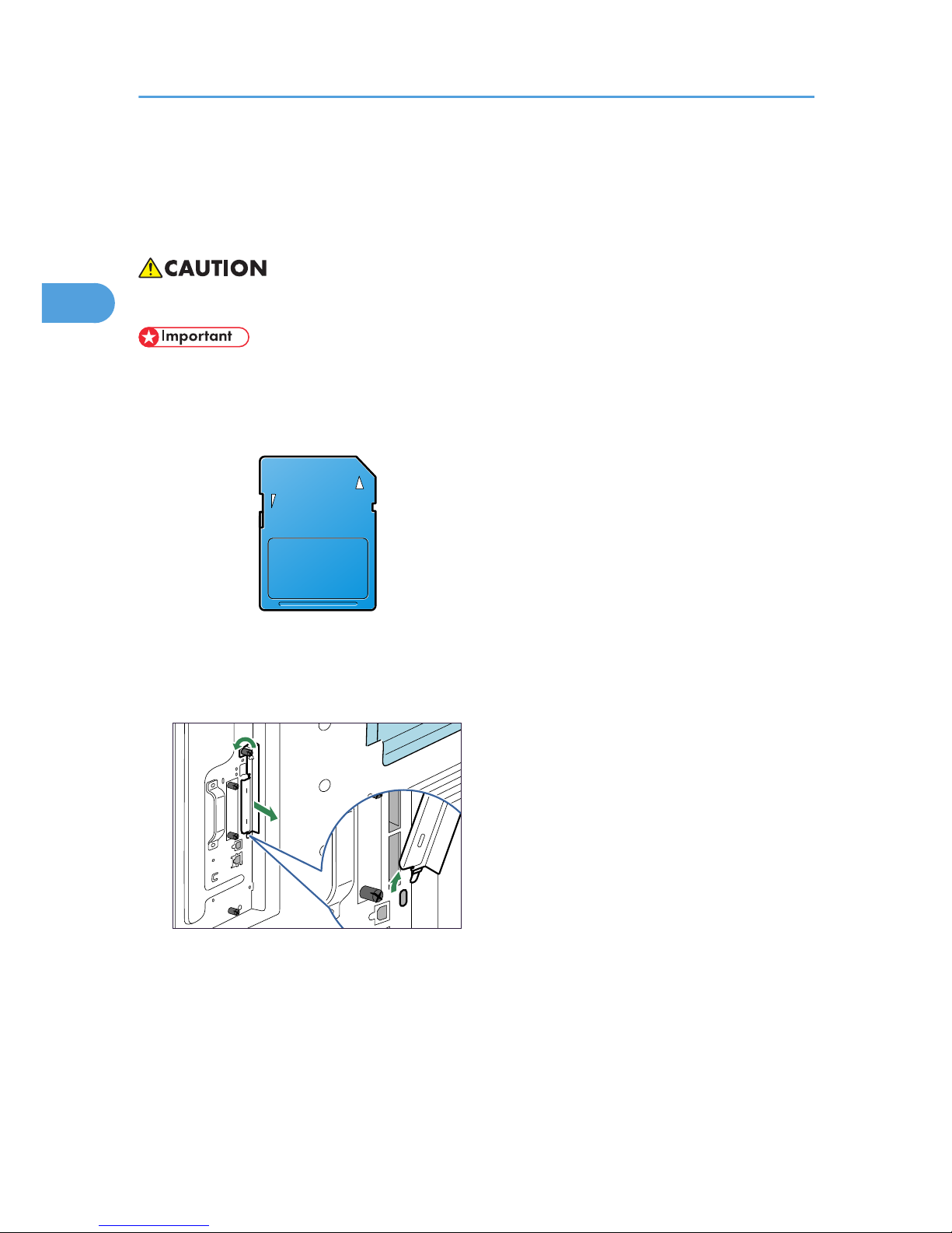
Installing SD Card Options
This section provides the procedure for installing the following SD cards: a data overwrite security unit,
data storage card, IPDS unit, HDD encryption unit, and VM card.
• Keep SD cards out of reach of children. If a child swallows a SD card, consult a doctor immediately.
• Do not subject the card to physical shocks.
1. Check the contents of the package.
BFL308S
2. Turn the printer off and unplug the power cord.
3. Loosen the screw and remove the SD card slot cover in angle.
BEK107S
2. Installing Options
46
2
Page 49
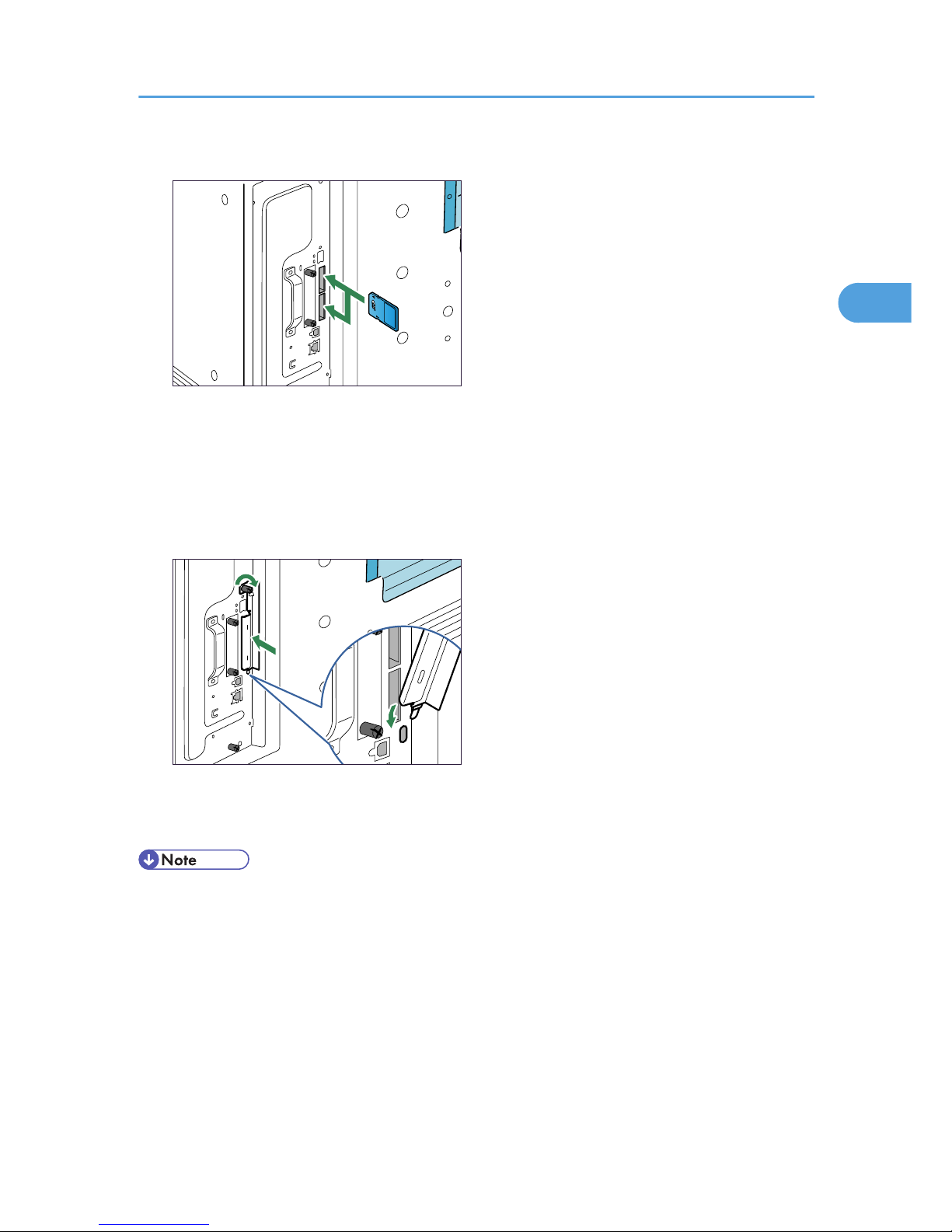
4. Insert the SD card into the slot until it clicks.
BEK149S
Insert the SD card in the appropriate slot as follows:
• Upper slot: data overwrite security unit, data storage card, or IPDS unit
• Lower slot: HDD encryption unit or VM card
5. Hook the SD card slot cover onto the opening, attach it flat against the controller board, and
then fasten it using the screw.
BEK150S
6. Plug in the power cord, and then turn on the printer.
7. See the control panel menu to confirm that the SD card was installed correctly.
• Do not touch the card while the printer is in use. The card may come loose, even if it is pushed only
slightly. The SD card slot cover must be reattached.
• You can confirm that the SD card was installed correctly by checking the control panel menu.
Depending on the SD card, certain menu items appear on the display.
• Data overwrite security unit: [Memory Erase Status] appears on the top level menu.
• IPDS unit: [IPDS Menu] appears in [Print Settings].
• HDD encryption unit: [Machine Data Encryption] appears in [Security Options].
• If the card is not installed properly, repeat the procedure from the beginning. If it cannot be installed
correctly even after reattempting installation, contact your sales or service representative.
Installing SD Card Options
47
2
Page 50

• For information on printing the configuration page, see "Test Printing", Quick Installation Guide.
2. Installing Options
48
2
Page 51
3. Connecting the Printer Cables
Ethernet Cable Connection
Prepare a hub and other network devices, and connect the Ethernet cable to the printer.
If you are connecting the printer using the printer's standard Ethernet port, use a 10BASE-T or 100BASETX cable.
If you are connecting the printer using the optional Gigabit Ethernet board, you can use a 1000BASE-T
cable, instead of a 10BASE-T or 100BASE-TX cable.
• A network interface cable with a ferrite core must be used for RF interference suppression.
• For users outside the United States of America: properly shielded and grounded cables and connectors
must be used for connections to a host computer (and/or peripheral) in order to meet emission limits.
• For users in the United States of America: properly shielded and grounded cables and connectors
must be used for connections to a host computer (and/or peripheral) in order to meet FCC emission
limits.
• An Ethernet cable is not supplied with this printer. Select your cable according to the network
environment.
• The printer's Ethernet port is not available when the Gigabit Ethernet board is attached to the printer.
• The Ethernet cable must be an Unshielded Twisted Pair cable (UTP) or Shielded Twisted Pair cable
(STP), and Category type 5 or more.
Connecting to the standard Ethernet port
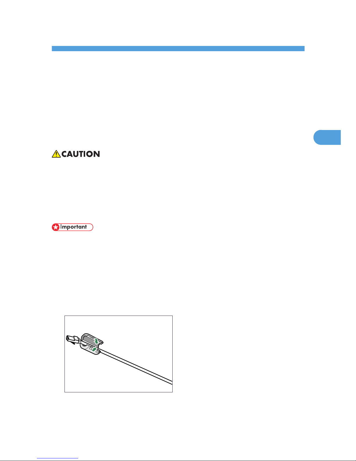
1. Attach the ferrite core supplied with this printer at the printer end of the Ethernet cable.
BEK096S
49
3
Page 52
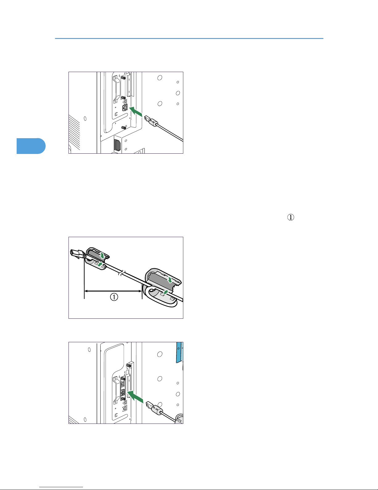
2. Connect the Ethernet cable to the Ethernet port that is located on the left side of the printer.
BEK151S
3. Connect the other end of the cable to the network, for example using a hub.
Connecting to the Ethernet port of the Gigabit Ethernet board
1. Attach the two ferrite cores to the Ethernet cable.
Attach the core supplied with the printer at the printer end of the Ethernet cable. Attach the core
supplied with the Gigabit Ethernet board about 10 cm (4 inches) from the connector ( ), making a
loop as shown.
BEK108S
2. Connect the Ethernet cable to the Ethernet port of the Gigabit Ethernet board.
BEK152S
3. Connecting the Printer Cables
50
3
Page 53
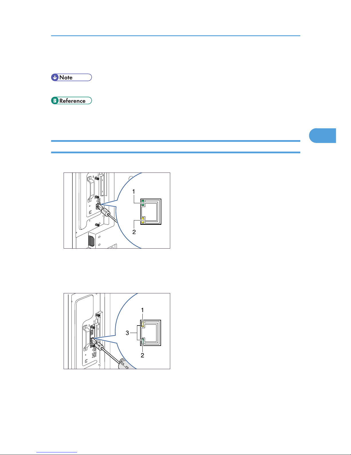
3. Connect the other end of the cable to a network hub, for example, to connect the printer to
the network.
• For details about configuring the network environment, see "Ethernet Configuration".
• p.37 "Installing the Gigabit Ethernet Board"
• p.55 "Ethernet Configuration"
Reading the LED Lamps
Standard Ethernet port
BEK153S
1. Green: turns on when the printer is properly connected to the network.
2. Yellow: turns on when 100BASE-TX is in use. It turns off when 10BASE-T is in use.
Ethernet port of the Gigabit Ethernet board
BEK154S
1. Yellow: turns on when 100BASE-TX is in use.
2. Green: turns on when 10BASE-T is in use.
3. Both the green and yellow lamps are lit when 1000BASE-T is in use.
Ethernet Cable Connection
51
3
Page 54
USB Cable Connection
• For users outside the United States of America: properly shielded and grounded cables and connectors
must be used for connections to a host computer (and/or peripheral) in order to meet emission limits.
• For users in the United States of America: properly shielded and grounded cables and connectors
must be used for connections to a host computer (and/or peripheral) in order to meet FCC emission
limits.
• USB connection is possible under Windows 2000/XP/ Vista, Windows Server 2003/2003 R2,
Mac OS 9.x, and Mac OS X.
• USB connection with Mac OS is only possible via the printer's USB port, not the Gigabit Ethernet
board's USB port.
• A USB cable is not supplied with this printer. Select your cable according to the computer.
• The printer's USB port is not available when the Gigabit Ethernet board is attached to the printer.
Connecting to the standard USB port
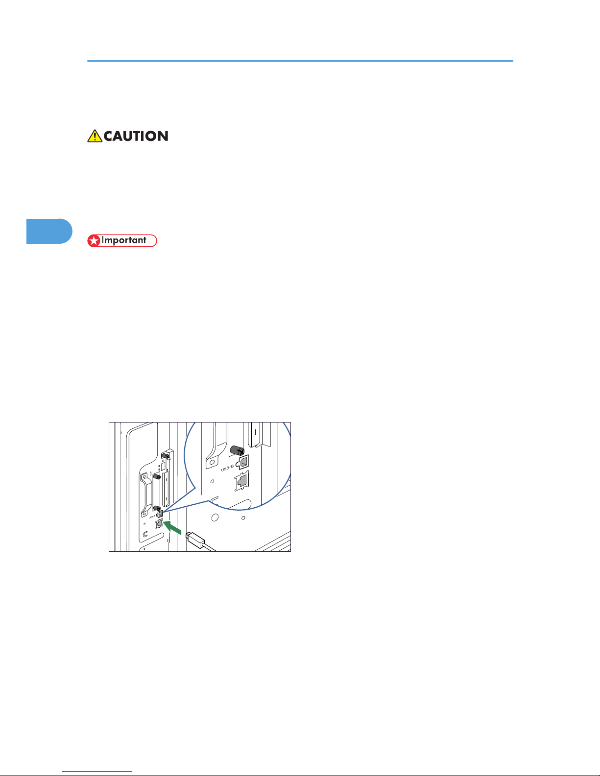
1. Connect the square-shaped connector of the USB cable to USB port B on the left side of the
printer.
BEK020S
2. Connect the opposite end's flat connector to the desired device such as your computer's USB
interface, or a USB hub.
3. Connecting the Printer Cables
52
3
Page 55
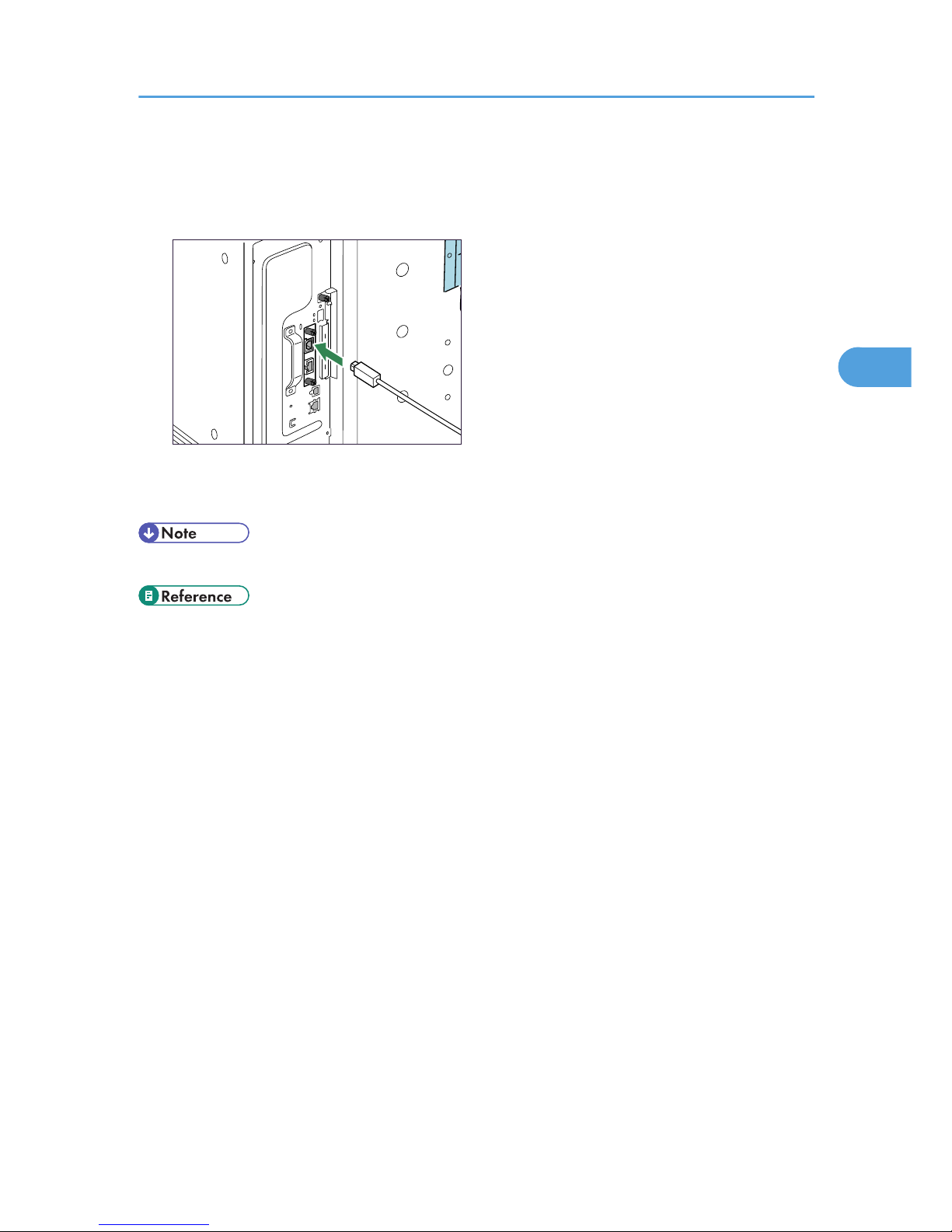
Connecting to the USB port of the Gigabit Ethernet board
1. Connect the square-shaped connector of the USB cable to the USB port of the Gigabit
Ethernet board.
BEK021S
2. Connect the opposite end's flat connector to the desired device such as your computer's USB
interface, or a USB hub.
• "Installing the Printer Driver Using USB", Software Guide
• p.37 "Installing the Gigabit Ethernet Board"
USB Cable Connection
53
3
Page 56
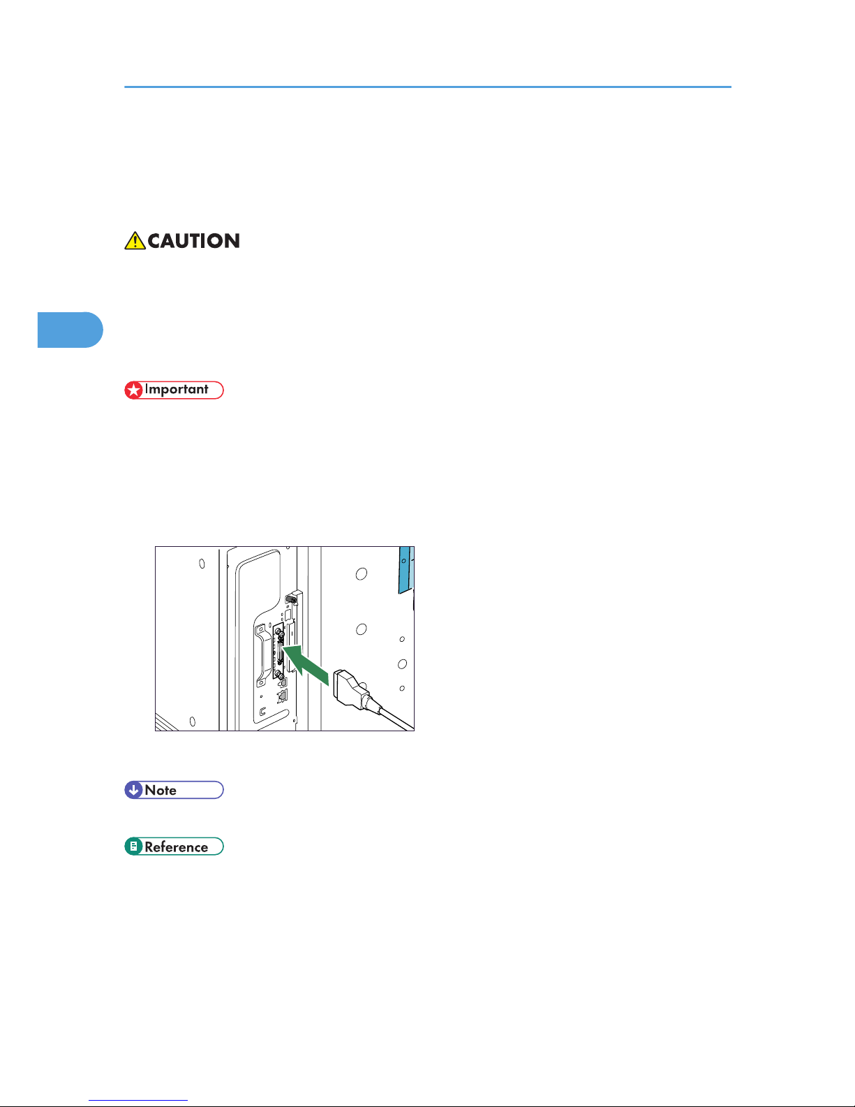
Parallel Cable Connection
The type of cable required varies depending on the computer you are using. Make sure to use the interface
cable compliant with your computer.
• For users outside the United States of America: properly shielded and grounded cables and connectors
must be used for connections to a host computer (and/or peripheral) in order to meet emission limits.
• For users in the United States of America: properly shielded and grounded cables and connectors
must be used for connections to a host computer (and/or peripheral) in order to meet FCC emission
limits.
• The printer's parallel connection is a standard bidirectional interface that requires an IEEE 1284compliant half pitch 36-pin parallel cable and host computer parallel port.
• Use shielded interface cable. Unshielded cables create electromagnetic interference.
1. Turn off the printer and computer.
2. Connect the interface cable to the IEEE 1284 interface board.
BEK158S
3. Connect the other end of the interface cable to your computer, and then secure the cable.
• "Preparing for Printing", Software Guide
• p.43 "Installing the IEEE 1284 Interface Board"
3. Connecting the Printer Cables
54
3
Page 57
4. Configuration
Ethernet Configuration
Configure the following network settings according to the network environment using the control panel.
• The following table shows the control panel settings and their default values. These items appear in
the [Host Interface] menu.
Setting Name Default
Machine IPv4 Address
• DHCP: On
• IPv4 Address: 11.22.33.44
• Subnet Mask: 0.0.0.0
• Gateway Address: 0.0.0.0
IPv6 Stateless Setting Active
IPsec Inactive
NW Frame Type Auto Select
Effective Protocol
• IPv4: Active
• IPv6: Inactive
• NetWare: Active
• SMB: Active
• Apple Talk: Active
Ethernet Speed Auto Select
LAN Type Ethernet
• If DHCP is in use on your network, the IP address, subnet mask, and gateway address are all set
automatically.
• If the printer is already placed on a TCP/IP-capable environment, you can also use
SmartDeviceMonitor for Admin or a Web browser to configure IP address-related settings.
55
4
Page 58
Specifying an IP Address (No DHCP)
Follow this procedure to assign a specific IP address to the printer. This is only necessary when you will use
the printer on a network without DHCP, or want to prevent the printer's IP address from changing.
Before beginning, make sure that you know the IP address, subnet mask and gateway address that the
printer will use.
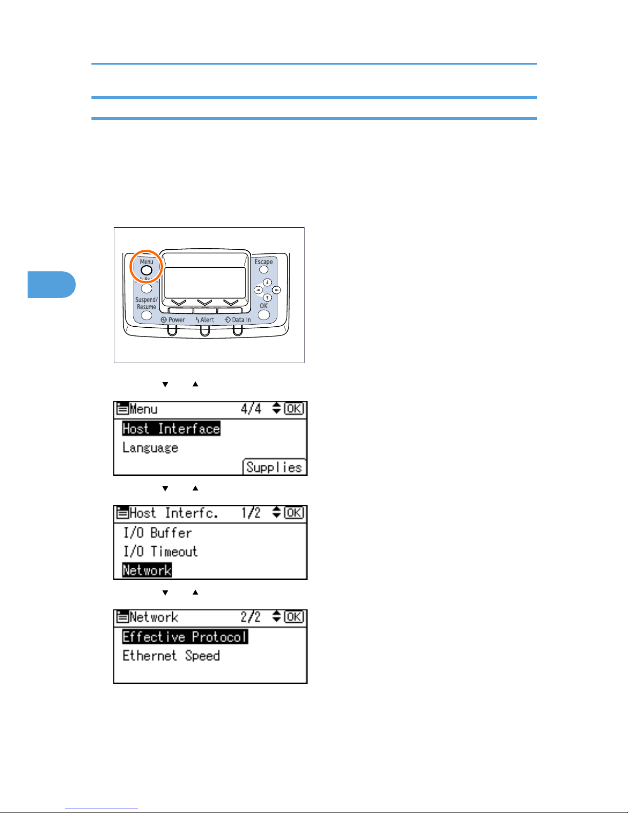
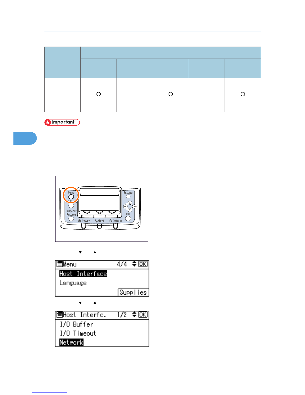
1. Press the [Menu] key.
BEK204S
2. Press the [ ] or [ ] key to select [Host Interface], and then press the [OK] key.
3. Press the [ ] or [ ] to select [Network], and then press the [OK] key.
4. Press the [ ] or [ ] key to select [Effective Protocol], and then press the [OK] key.
4. Configuration
56
4
Page 59
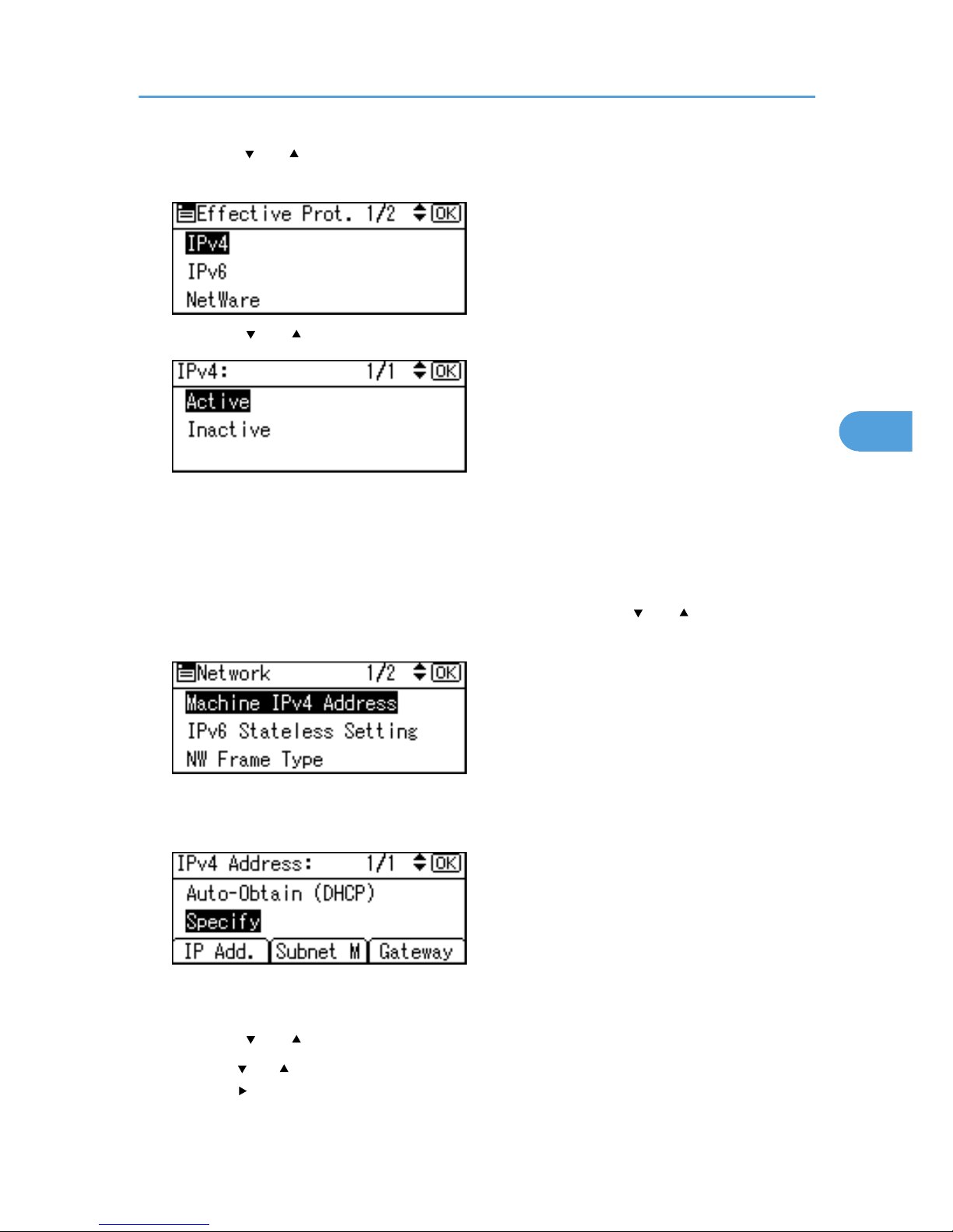
5. Press the [ ] or [ ] key to select the appropriate network protocol, and then press the [OK]
key.
6. Press the [ ] or [ ] key to select [Active] or [Inactive], and then press the [OK] key.
Set other protocols you need to set in the same way.
• Select [Inactive] for unused protocols.
• Enable IPv4 to use the pure IPv4 environment of NetWare5/5.1, Netware 6/6.5.
7. Press the [Escape] key until the screen returns to the [Network] menu.
8. If you use IPv4, assign the IPv4 address to the printer. Press the [ ] or [ ] key to select
[Machine IPv4 Address], and then press the [OK] key.
To get the IP address for the printer, contact your network administrator.
9. To specify the IP address, press [IP Add].
If you use IPv4, also assign the subnet mask and gateway address. To assign these, press [Subnet M]
or [Gateway].
10. Press the [ ] or [ ] to enter the address, and then press the [OK] key.
Press the [ ] or [ ] key to enter the left-most entry field of the address. After entering the left field,
press the [ ] key, and then you can enter the next field. After completing entry of the all fields, press
the [OK] key. Use the same method to assign the subnet mask and gateway address.
Ethernet Configuration
57
4
Page 60
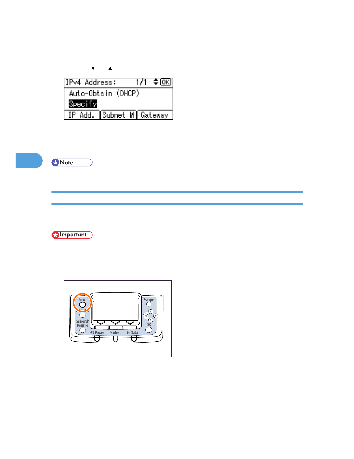
• Change the IP address from “11.22.33.44” to an IP address supported by your network.
11. Press the [ ] or [ ] key to select [Specify], and then press the [OK] key.
If you do not select [Specify] in this step, the address you set will not be saved.
12. Press the [Menu] key to return to the initial screen.
13. Print a configuration page to confirm the settings.
• For details about printing the configuration page, see “Test printing”, Quick Installation Guide.
Receiving an IP Address Automatically (DHCP)
Follow this procedure to set the printer to receive an IP address automatically using DHCP. The DHCP
feature is active by default, so this procedure is only required if you have changed the default settings.
• When [DHCP] is selected, you cannot configure the IP address, subnet mask, or gateway address.
• Consult your network administrator for information about configuring network settings.
1. Press the [Menu] key.
BEK204S
4. Configuration
58
4
Page 61
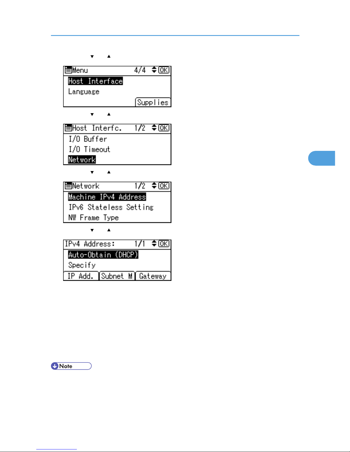
2. Press the [ ] or [ ] key to select [Host Interface], and then press the [OK] key.
3. Press the [ ] or [ ] key to select [Network], and then press the [OK] key.
4. Press the [ ] or [ ] key to select [Machine IPv4 Address], and then press the [OK] key.
5. Press the [ ] or [ ] key to select [Auto-Obtain (DHCP)], and then press the [OK] key.
The printer will automatically receive an IP address.
To check the detected addresses, press the following:
• [IP Add.] : IP address
• [Subnet M] : Subnet mask
• [Gateway] : Gateway address
6. Press the [Menu] key to return to the initial screen.
7. Print a configuration page to confirm the settings.
• For details about printing the configuration page, see “Test printing”, Quick Installation Guide.
Ethernet Configuration
59
4
Page 62
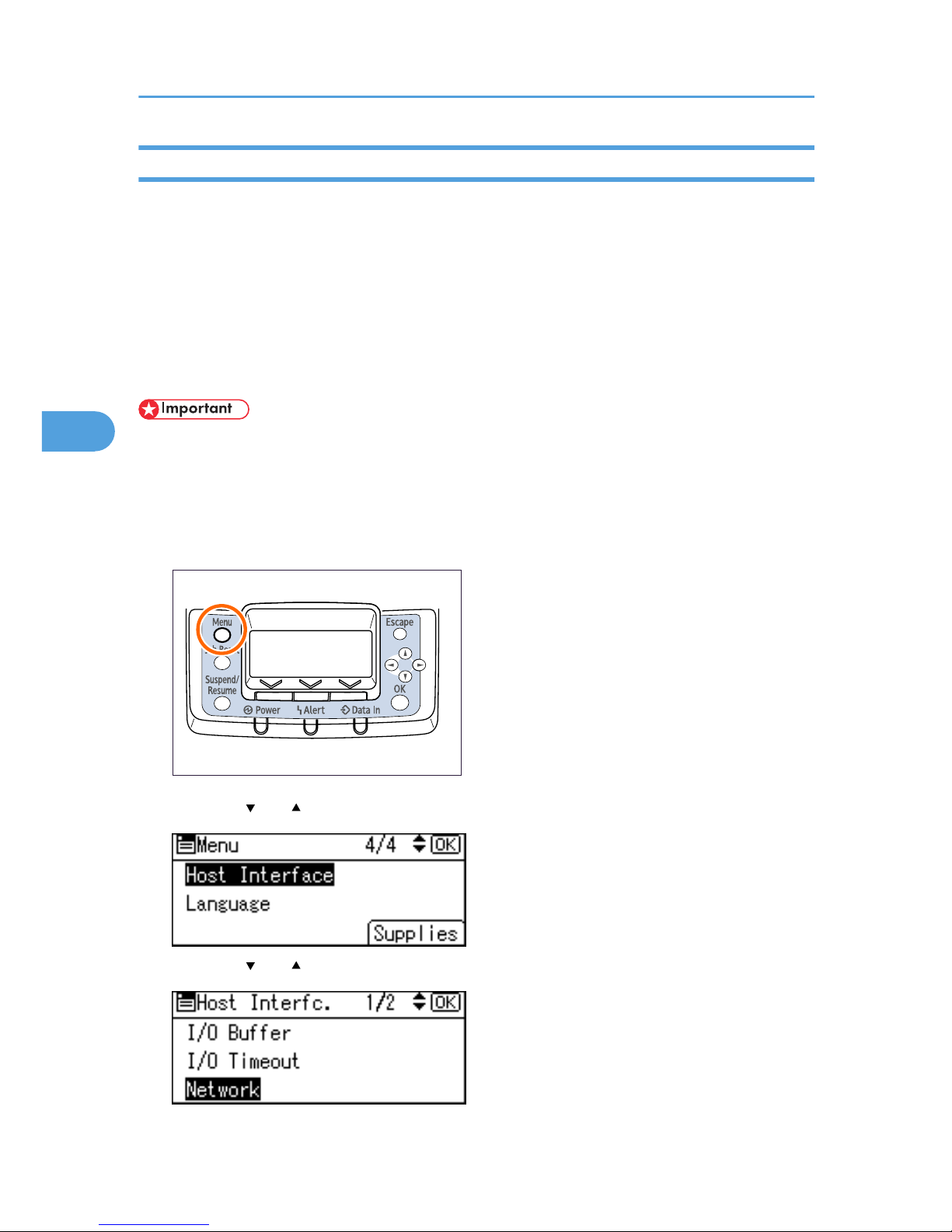
Configuring Network Settings When Using NetWare
If you use NetWare, select the appropriate NetWare frame type.
Select one of the items below as necessary.
• Auto Select
• Ethernet II
• Ethernet 802.2
• Ethernet 802.3
• Ethernet SNAP
• Usually, you can use the default (Auto Select). When you first select [Auto Select,] the frame type
detected by the printer is adopted. However, if your network can use more than two frame types, the
printer may fail to select the correct frame type with [Auto Select] selected. In this case, select the
preferred frame type.
1. Press the [Menu] key.
BEK204S
2. Press the [ ] or [ ] key to select [Host Interface], and then press the [OK] key.
3. Press the [ ] or [ ] key to select [Network], and then press the [OK] key.
4. Configuration
60
4
Page 63
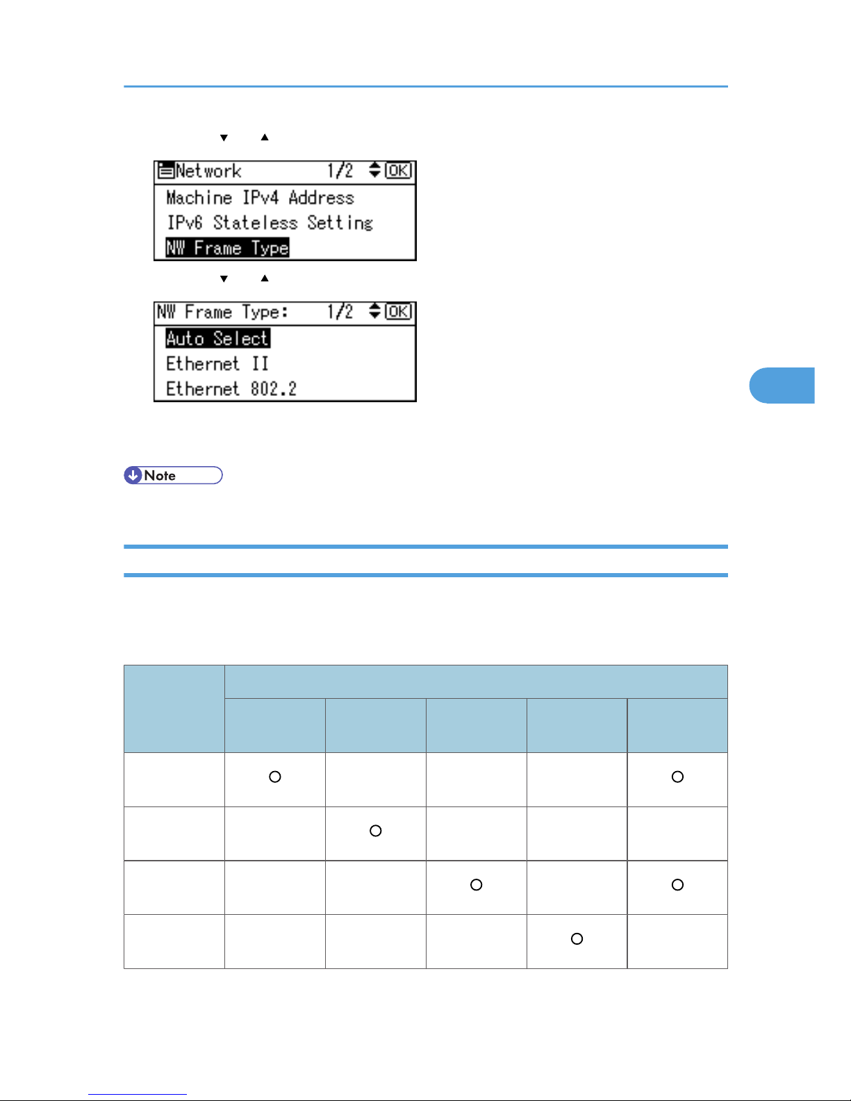
4. Press the [ ] or [ ] key to select [NW Frame Type], and then press the [OK] key.
5. Press the [ ] or [ ] key to select the frame type to use, and then press the [OK] key.
6. Press the [Menu] key to return to the initial screen.
7. Print a configuration page to confirm the settings.
• For details about printing the configuration page, see “Test printing”, Quick Installation Guide.
Setting the Ethernet Speed
You can set the speed that the printer will use for Ethernet communications. In most cases, this should be
left on the default setting, [Auto Select]. This setting allows two interfaces to automatically determine the
optimum speed when they are connected.
Router/HUB
Printer
[10Mbps Half
D.]
[10Mbps Full
D.]
[100Mbps
Half D.]
[100Mbps Full
D.]
[Auto Select]
10 Mbps half
duplex
- - -
10 Mbps full
duplex
- - - -
100 Mbps half
duplex
- - -
100 Mbps full
duplex
- - - -
Ethernet Configuration
61
4
Page 64
Router/HUB
Printer
[10Mbps Half
D.]
[10Mbps Full
D.]
[100Mbps
Half D.]
[100Mbps Full
D.]
[Auto Select]
autonegotiation
(auto
selection)
- -
• Connection cannot be established if the selected Ethernet speed does not match your network's
transmission speed.
• The auto-negotiation mechanism allows two interfaces to automatically determine an optimum
Ethernet speed as soon as they are connected. We recommend you select [Auto Select].
1. Press the [Menu] key.
BEK204S
2. Press the [ ] or [ ] key to select [Host Interface], and then press the [OK] key.
3. Press the [ ] or [ ] key to select [Network], and then press the [OK] key.
4. Configuration
62
4
Page 65
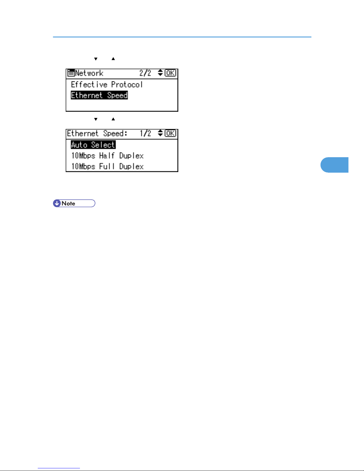
4. Press the [ ] or [ ] key to select [Ethernet Speed], and then press the [OK] key.
5. Press the [ ] or [ ] key to select the Ethernet speed, and then press the [OK] key.
6. Press the [Menu] key to return to the initial screen.
7. Print a configuration page to confirm the settings.
• For details about printing the configuration page, see "Test Printing", Quick Installation Guide.
Ethernet Configuration
63
4
Page 66
Wireless LAN Configuration
Configure the following wireless LAN settings according to the network environment using the control panel.
• Ethernet and Wireless LAN cannot be used at the same time.
• To use wireless LAN, set as follows using the control panel: press the [Menu] key, select [Host
Interface], [Network], [LAN Type], and then select [Wireless LAN]. In addition, you must set the IP
address, subnet mask, gateway address, DHCP, Frame Type (NW), and active protocol as explained
in "Ethernet Configuration".
• The following table shows the control panel settings and their defaults. These items appear in the [Host
Interface] menu.
Setting Name Default
Communication Mode Infrastructure Mode
Ad-hoc Channel
• When using the IEEE 802.11a/g Interface
Board:
36
• When using the IEEE 802.11g Interface
Board:
11
Communication Speed Auto
SSID Setting blank
Security Method None
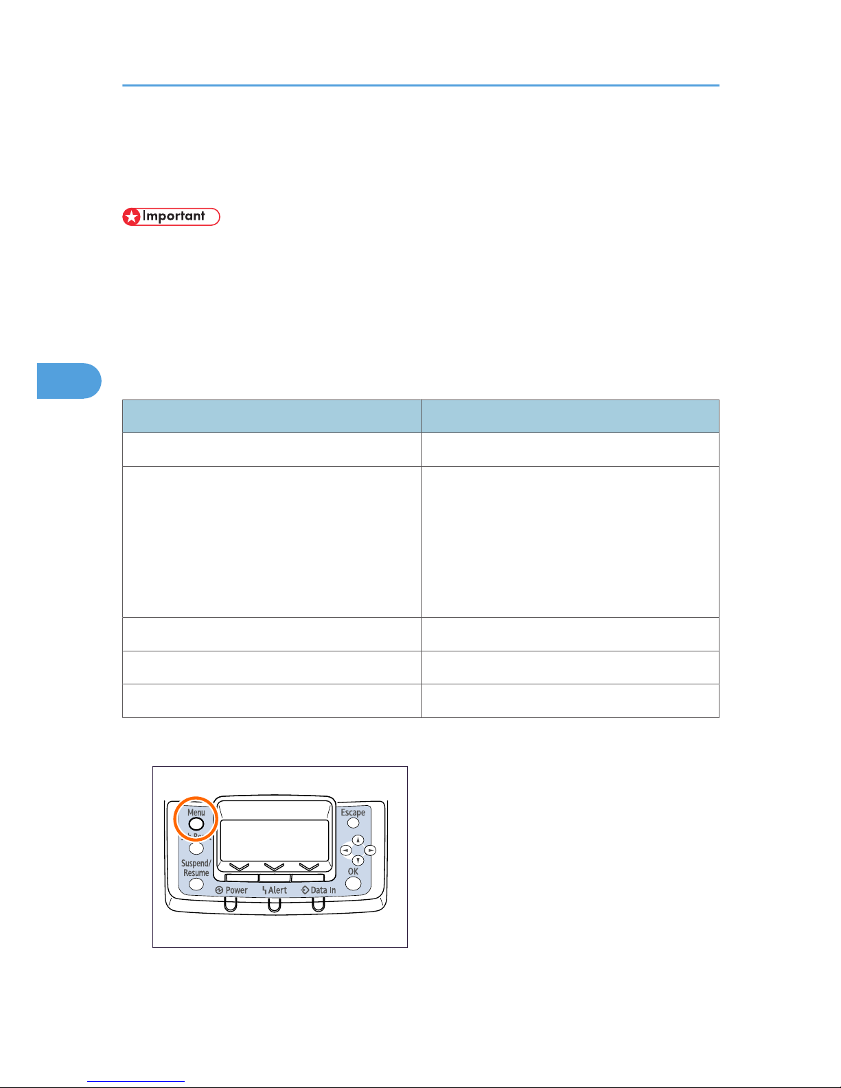
1. Press the [Menu] key.
BEK204S
4. Configuration
64
4
Page 67
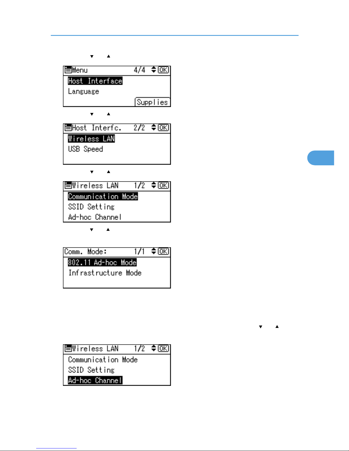
2. Press the [ ] or [ ] key to select [Host Interface], and then press the [OK] key.
3. Press the [ ] or [ ] key to select [Wireless LAN], and then press the [OK] key.
4. Press the [ ] or [ ] key to select [Communication Mode], and then press the [OK] key.
5. Press the [ ] or [ ] key to select the transmission mode of the wireless LAN, and then press
the [OK] key.
• To communicate wirelessly with a device that does not require an SSID to be set, select [802.11
Ad-hoc Mode].
• The transmission mode of the wireless LAN can also be set using Web Image Monitor.
6. If [802.11 Ad-hoc Mode] is selected for [Communication Mode], press the [ ] or [ ] key to
select [Ad-hoc Channel], and then press the [OK] key.
Wireless LAN Configuration
65
4
Page 68
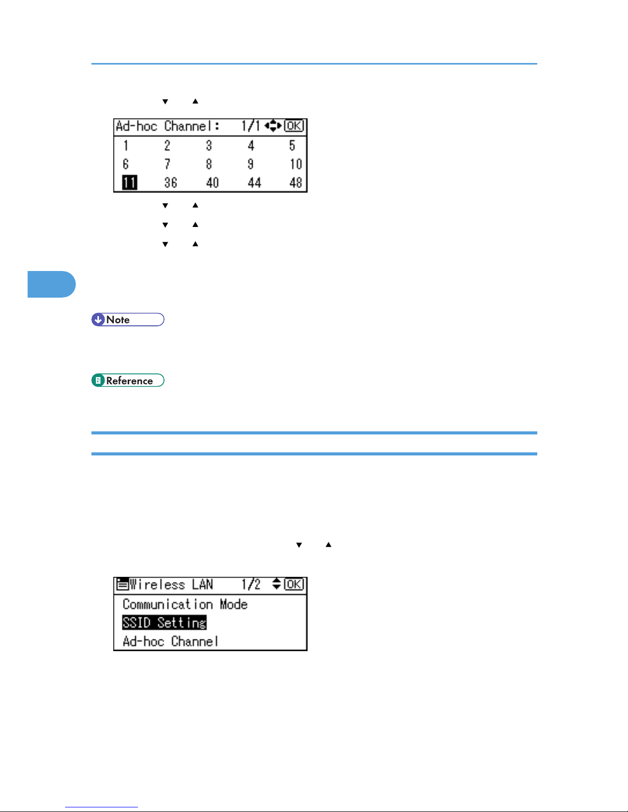
7. Press the [ ] or [ ] key to select the Ad-hoc channel, and then press the [OK] key.
8. Press the [ ] or [ ] key to select the appropriate channel, and then press the [OK] key.
9. Press the [ ] or [ ] key to select [Communication Speed], and then press the [OK] key.
10. Press the [ ] or [ ] key to select the appropriate speed, and then press the [OK] key.
The default is [Auto]. If you need to change the transmission speed depending on the environment
you are using, select the appropriate speed.
11. Print a configuration page to confirm the settings.
• For details, see Web Image Monitor Help, and “Using Web Image Monitor”, Software Guide.
• For details about printing the configuration page, see “Test Printing”, Quick Installation Guide.
• p.55 "Ethernet Configuration"
Setting the SSID
When [Communication Mode] is set to [Infrastructure Mode] or [802.11 Ad-hoc Mode], you must specify
the Service Set Identifier (SSID) of the wireless access point that the printer will connect to for network
access.
Ask the network administrator for the SSID to use.
1. In the [Wireless LAN] menu, press the [ ] or [ ] key to select [SSID Setting], and then press
the [OK] key.
If an SSID has been set, you can check the current SSID setting.
2. Press [Enter].
4. Configuration
66
4
Page 69
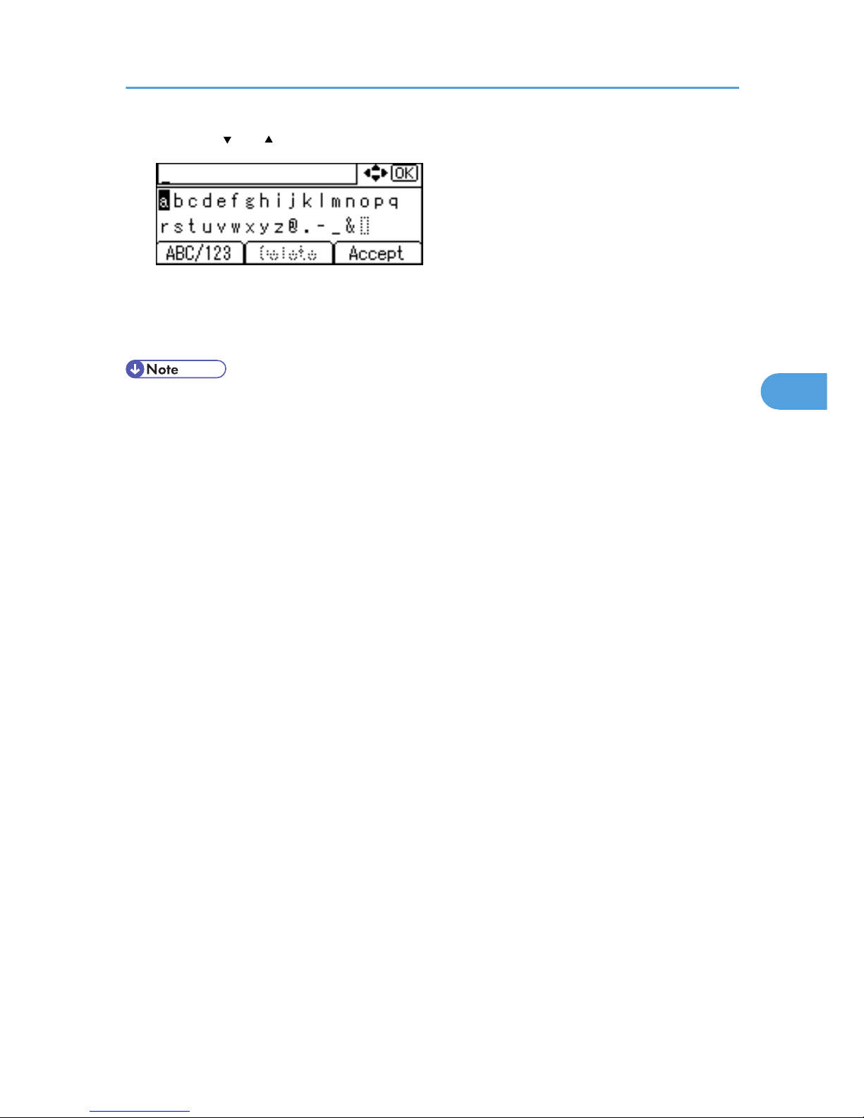
3. Press the [ ] or [ ] key to enter characters, and then press [Accept].
You can switch among upper/lower cases, numeric codes, and symbols by pressing [ABC/123].
The characters that can be used are ASCII 0 × 20-0 × 7e (32 bytes).
4. Print a configuration page to confirm the settings.
• The SSID can also be set using a Web browser. For details, see the Web Image Monitor Help, and
"Configuring the Network Interface Board", Software Guide. For details about printing the
configuration page, see "Test Printing", Quick Installation Guide.
Wireless LAN Configuration
67
4
Page 70
Setting Security Method of Wireless LAN
Setting a WEP Key
If the wireless network uses WEP to encrypt transmitted data, the corresponding WEP key must be set to
the printer to allow communications with other network devices.
Ask the network administrator for the WEP key to use.
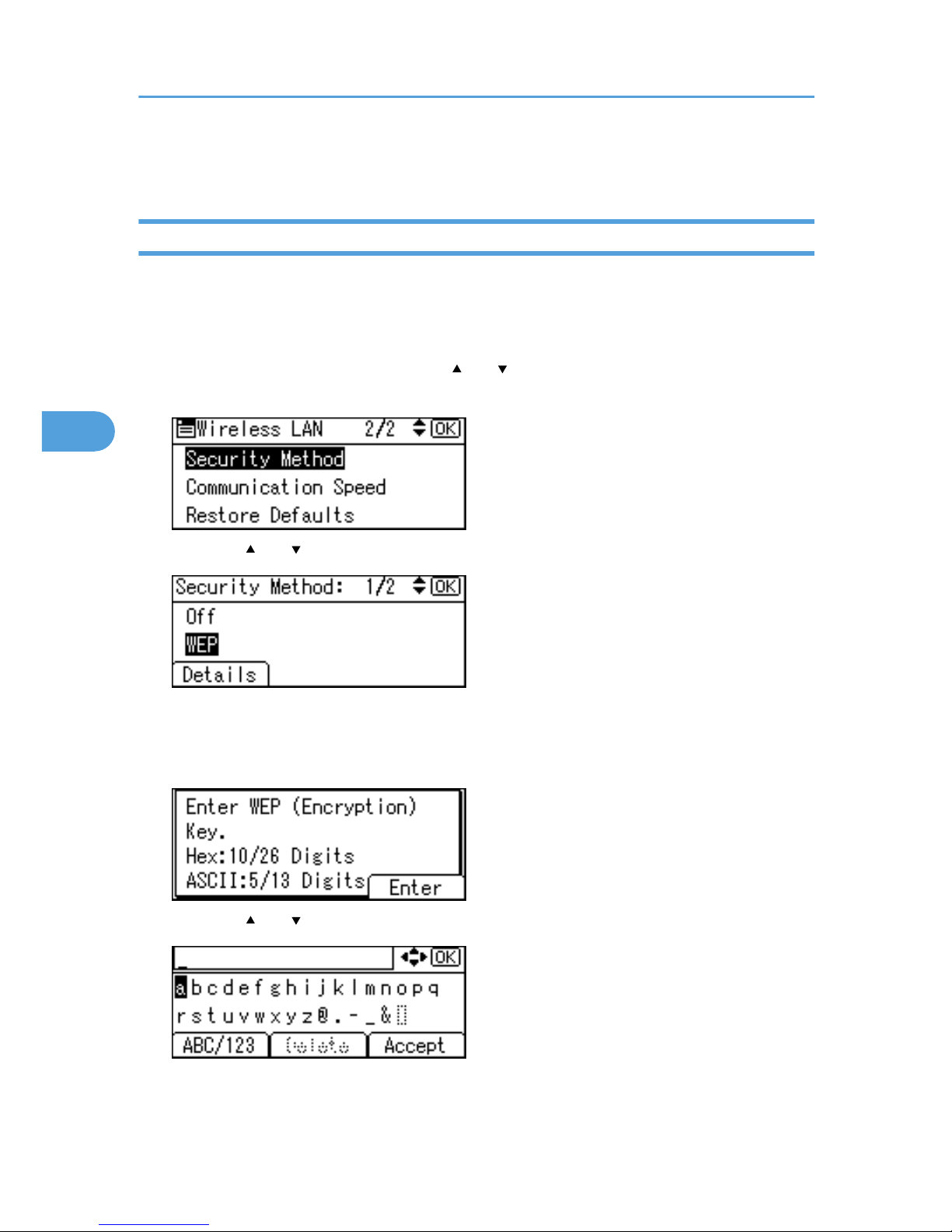
1. In the [Wireless LAN] menu, press the [ ] or [ ] key to select [Security Method], and then
press the [OK] key.
2. Press the [ ] or [ ] key to select [WEP], and then press [Details].
When activating the WEP setting, you will need to enter the WEP key. If you have not entered the key,
be sure to enter it.
3. A confirmation message appears. Press [Enter].
4. Press the [ ] or [ ] key to enter characters, and then press [Accept].
• When entering a character, pressing [Accept] will mask it with an asterisk for security reasons.
4. Configuration
68
4
Page 71
• When using 64-bit WEP, up to 10 hexadecimal characters or five ASCll characters can be
entered. When using 128-bit WEP, up to 26 hexadecimal characters or 13 ASCll characters
can be used.
• Up to 10 or 26 hexadecimal characters and 5 or 13 ASCll characters can be entered.
• For ASCII character strings, uppercase and lowercase letters are differentiated, so be sure to
enter characters in the required case.
5. Press the [Menu] key to return to the initial screen.
6. Print a configuration page to confirm the settings.
• The WEP key can also be set using a Web browser. For details, see the Web Image Monitor Help.
• For details about printing the configuration page, see “Test Printing”, Quick Installation Guide.
Setting WPA
In the case of using WPA on a network, activate the WPA setting to be used for communication along with
WPA. Consult your network administrator for information about making authentication settings.
• For setting WPA, installing the optional HDD or the optional Data Storage Card is required.
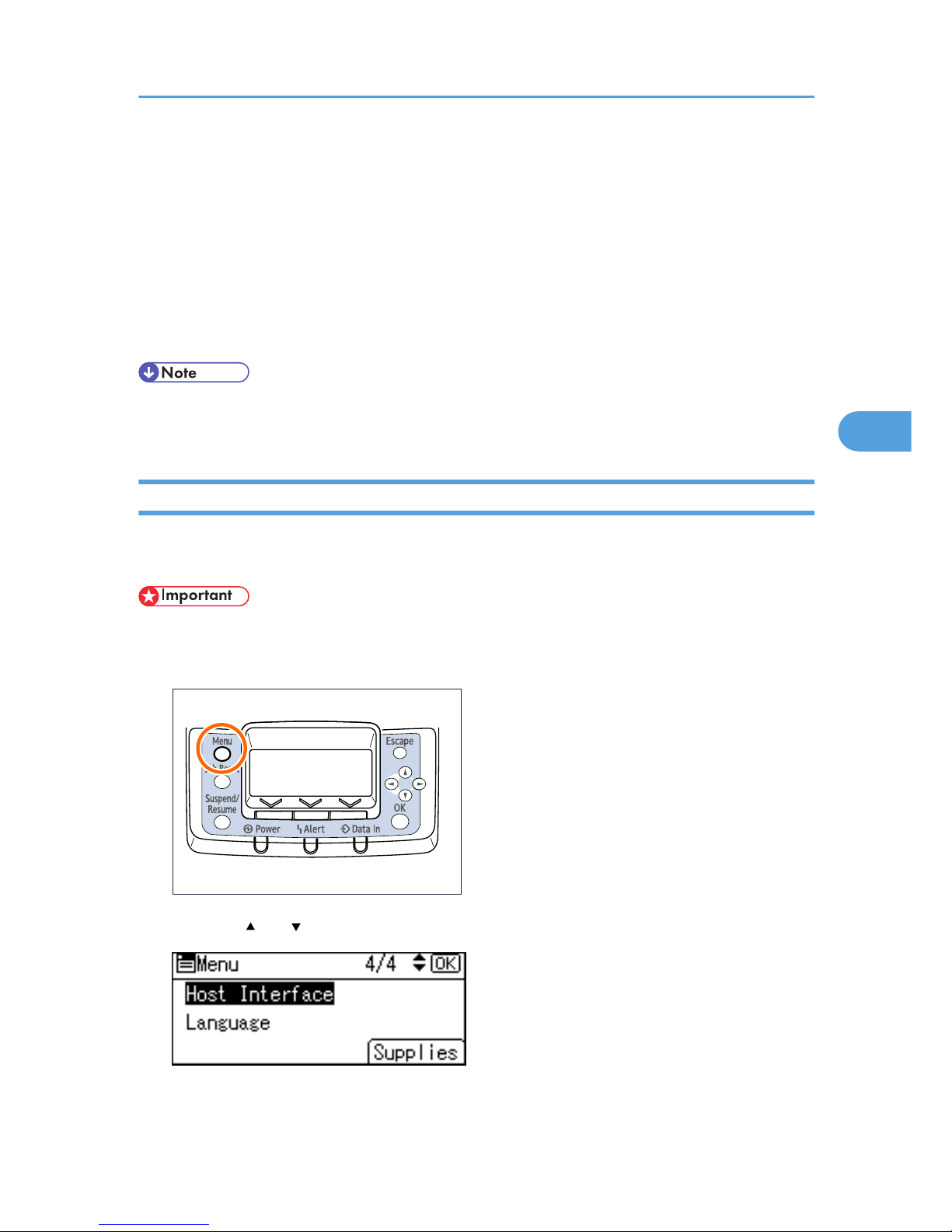
1. Press the [Menu] key.
BEK204S
2. Press the [ ] or [ ] key to select [Host Interface], and then press the [OK] key.
Setting Security Method of Wireless LAN
69
4
Page 72
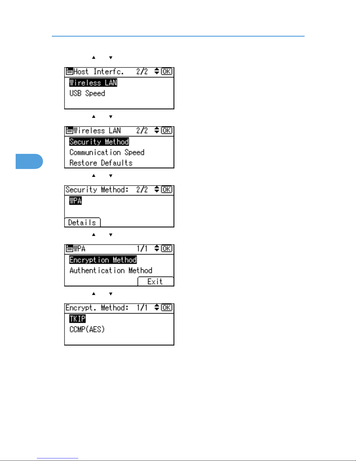
3. Press the [ ] or [ ] key to select [Wireless LAN], and then press the [OK] key.
4. Press the [ ] or [ ] key to select [Security Method], and then press the [OK] key.
5. Press the [ ] or [ ] key to select [WPA], and then press [Details].
6. Press the [ ] or [ ] key to select [Encryption Method], and then press the [OK] key.
7. Press the [ ] or [ ] key to select encryption method, and then press the [OK] key.
Consult your network administrator for information about making encryption settings.
Encryption settings are as follows:
• [TKIP]
Uses the same algorithm as RC4, but further reduces vulnerability using methods such as key
mixing.
• [CCMP(AES)]
Increases security using AES (Advanced Encryption Standard).
4. Configuration
70
4
Page 73
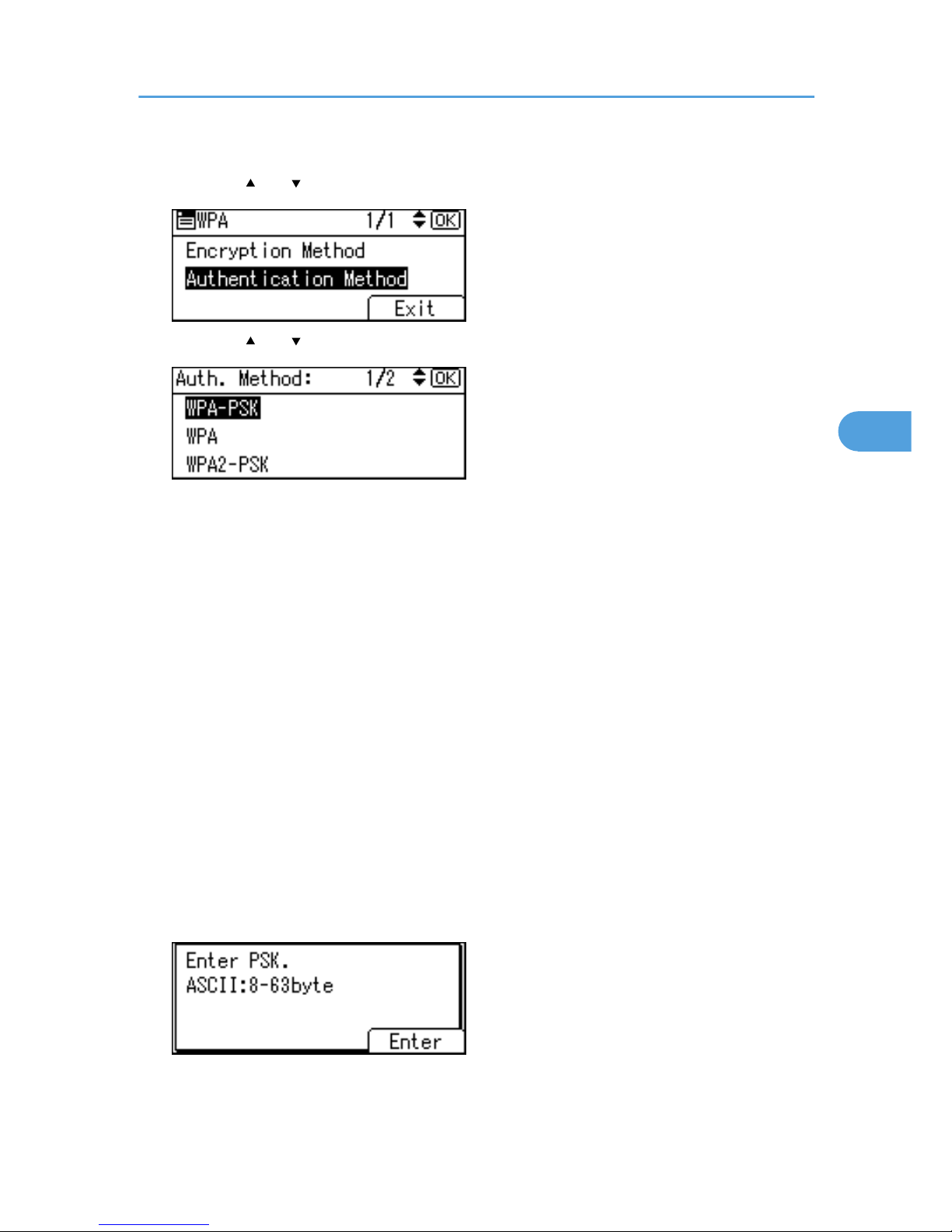
Wait for two seconds. The display returns to the [WPA] menu.
8. Press the [ ] or [ ] key to select [Authentication Method], and then press the [OK] key.
9. Press the [ ] or [ ] key to select authentication method, and then press the [OK] key.
Authentication settings are as follows:
• [WPA-PSK]
Performs authentication using an encryption key (a Pre-Shared Key) that is shared by the access
point and client.
• [WPA]
WPA uses CA certificates and a RADIUS server to provide secure wireless communication.
• [WPA2-PSK]
As with WPA-PSK, authenticate using the encryption key (a Pre-Shared Key) shared by the access
point and client.
• [WPA2]
WPA2 is an expanded version of WPA that fully supports IEEE802.11i.
10. If [WPA] or [WPA2] is selected in step 9, a confirmation message appears. Press the [OK]
key.
Wait for two seconds. The display returns to the [WPA] menu.
11. If [WPA-PSK] or [WPA2-PSK] is selected in step 9, a confirmation message appears. Press
[Enter].
Setting Security Method of Wireless LAN
71
4
Page 74
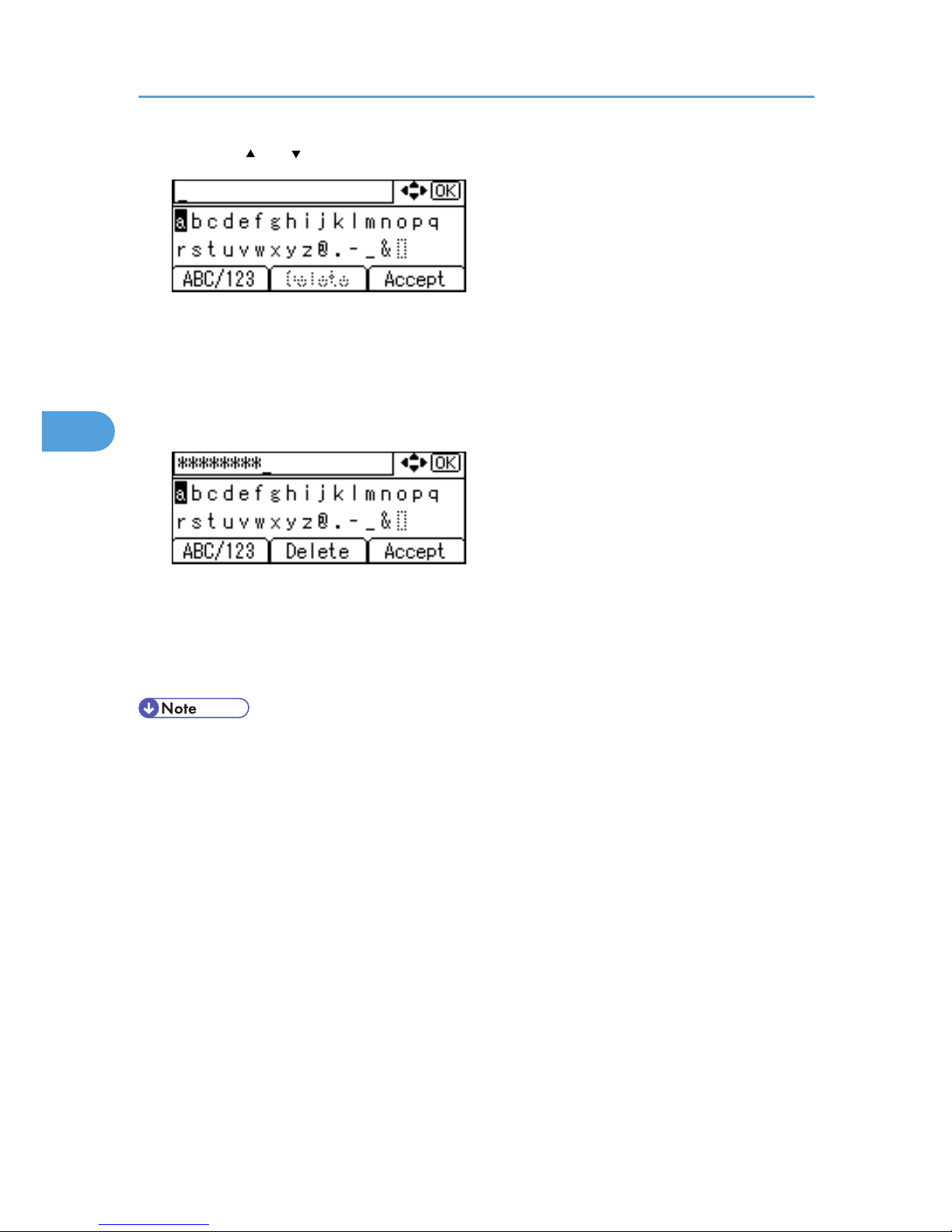
12. Press the [ ] or [ ] key to enter the Pre-Shared Key, and then press the [OK] key.
• When entering a character, pressing [OK] will mask it with an asterisk for security reasons.
• Enter the Pre-Shared Key using between 8 and 63 ASCII characters.
• Uppercase and lowercase letters are differentiated, so be sure to enter characters in the required
case.
13. When all characters have been entered, press [Accept].
Wait for two seconds. The display returns to the [Auth. Method] menu.
14. Press the [Menu] key.
The initial screen appears.
15. Print a configuration page to confirm the settings.
• For details about printing a configuration page, see “Test Printing”, Quick Installation Guide.
4. Configuration
72
4
Page 75

Configuring WPA/WPA2
WPA/WPA2 uses an authentication server to provide greatly enhanced security compared to WPA-PSK/
WPA2-PSK
WPA/WPA2 can be configured using Web Image Monitor's administrator mode. You can select four types
of EAP authentication method: EAP-TLS, LEAP, EAPTTLS and PEAP. Note that each EAP authentication
method has different configuration settings and authentication procedures.
Types and requirements of certificates are as follows:
If a certificate is required, configure all settings after installing the certificate.
EAP Types Requiring a “Site Certificate”
EAP-TLS, EAP-TTLS, PEAP (Necessary except LEAP)
EAP Types Requiring a “Site Certificate” and a “Device Certificate”
EAP-TLS, PEAP (Phase 2 is for TLS only)
• To set WPA/WPA2, you must enable SSL.
• To set WPA/WPA2, you must use Web Image Monitor.
Installing a Site Certificate
1. Access the authentication server and obtain the CA certificate.
Methods of obtaining certificates differ according to the operating system you are using.
2. Start your Web browser.
3. Enter "http://(printer's address)/" in the address bar of a Web browser.
4. Enter your user name and password, and then click [Login].
For details about the login user name and password, consult your administrator.
5. Click [Configuration].
6. [Site Certificate] in the “Security” area.
7. Click [Browse] on the “Site Certificate to Import” window, and then select the CA certificate
you obtained.
8. Click [Import].
9. Click [OK].
10. Click [Logout].
11. Quit the Web browser.
Configuring WPA/WPA2
73
4
Page 76

Installing Device Certificate
Depending on the settings of your choice, certain steps in the following procedure may not be required.
1. Start your Web browser.
2. Enter "http://(printer's address)/" in the address bar of a Web browser.
3. Enter your user name and password, and then click [Login].
For details about the login user name and password, consult your administrator.
4. Click [Configuration].
5. Click [Device Certificate] in “Security” area.
6. Check [Certificate1] or [Certificate2] on the “Device Certificate” window, and then click
[Request].
7. Enter appropriate “Common Name” and “Country Code” on “Certificate Information”
page, and then click [OK].
8. “Updating...” appears. Wait for about 2 minutes, and then click [OK].
9. Click [Details], shown in the “Device Certificate” window as the memo pad icon for
“Requesting”.
10. Select all, and then copy the entire “Text for Requested Certificate” text that is displayed in
the “Certificate Status” window.
11. Access the certificate authority server, and then obtain the CA signified certificate using the
text copied into “Text for Requested Certificate” windows.
Obtaining the certificate differs depending on the environment you want to use.
12. Click [Certificate 1] or [Certificate 2] on “Device Certificate” window, and then click [Install].
If you have selected [Certificate 1] in step 6, click [Certificate 1] in this step. If you have selected
[Certificate 2] in step 6, click [Certificate 2] in this step.
13. Using a text editor, open the CA signified certificate downloaded in step 11, and then copy
over all the text.
14. In the [Install Certificate] window, paste all the text copied into the CA signified certificate.
15. Click [OK].
16. “Updating...” appears. Wait for about one or two minutes, and then click [OK].
Check that the “Device Certificate” shows “Installed”.
17. Click [Certificate 1] or [Certificate 2] on “Certification”, and then click [OK].
If you have selected [Certificate 1] in step 6, click [Certificate 1] in this step. If you have selected
[Certificate 2] in step 6, click [Certificate 2] in this step.
18. Click [Logout].
19. Quit the Web browser.
4. Configuration
74
4
Page 77

• If you request two certificates simultaneously, the certificate authority might not display either
certificate. Click [Cancel Request] to cancel the request.
• Click [Cancel Request] to cancel the request for the server certificate.
• If “Not found” appears after clicking [OK] in steps 8 and 16, wait one or two minutes, and then click
[Refresh].
Setting Items of WPA/WPA2
1. Start your Web browser.
2. Enter "http://(printer's address)/" in the address bar of a Web browser.
3. Enter your user name and password, and then click [Login].
For details about the login user name and password, consult your administrator.
4. Click [Configuration], and then click [Wireless LAN Settings] in the “Interface” area.
5. Select [Infrastructure Mode] in “Communication Mode”.
6. Enter the alphanumeric characters (a-z, A-Z, or 0-9) in [SSID] according to the access point
you want to use.
7. Select [WPA] in “Security Method”.
8. Select [TKIP] or [CCMP (AES)] in “WPA Encryption Method” according to the access point
you want to use.
9. Select [WPA] or [WPA2] in “WPA Authentication Method”.
10. In “User Name”, enter the user name set in the RADIUS server.
11. Enter the domain name in “Domain Name”.
12. Select “EAP Type”. Configurations differ according to the EAP Type.
EAP-TLS
• Make the following settings according to the operating system you are using:
• Select the client certificate you want to use in "WPA Client Certificate".
• Select [On] or [Off] in “Authenticate Server Certificate”.
• Select [On] or [Off] in “Trust Intermediate Certificate Authority”.
• Enter the host name of the RADIUS server on “Server ID”.
• Select [On] or [Off] in “Permit Sub-domain”.
LEAP
• Click [Change] in “Password”, and then enter the password set in the RADIUS server.
EAP-TTLS
• Click [Change] in “Password”, and then enter the password set in the RADIUS server.
Configuring WPA/WPA2
75
4
Page 78

• Click [Change] in “Phase 2 User Name”, and then enter the user name set in the RADIUS server.
• Select [CHAP], [MSCHAP], [MSCHAPv2], [PAP], or [MD5] in “Phase 2 Method”.
• Certain methods might not be available, depending on the RADIUS server you want to use.
• Make the following settings according to the operating system you are using:
• Select [On] or [Off] in “Authenticate Server Certificate”.
• Select [On] or [Off] in “Trust Intermediate Certificate Authority”.
• Enter the host name of the RADIUS server in “Server ID”.
• Select [On] or [Off] in “Permit Sub-domain”.
PEAP
• Select [MSCHAPv2] or [TLS] in “Phase 2 Method”.
• When you select [TLS], select the client certificate you want to use in “WPA Client Certificate”.
• When you select [MSCHAPv2],
• click [Change] in “Password”, and then enter the password set in the RADIUS server.
• click [Change] on “Phase 2 User Name”, and then enter the user name set in the RADIUS
server.
• Make the following settings according to the operating system you are using:
• Select [On] or [Off] in “Authenticate Server Certificate”.
• Select [On] or [Off] in “Trust Intermediate Certificate Authority”.
• Enter the host name of the RADIUS server on “Server ID”.
• Select [On] or [Off] in “Permit Sub-domain”.
13. Click [OK].
14. Click [Logout].
15. Quit the Web browser.
• You can select [Certificate 1] or [Certificate 2] in the “Device Certificate” window. Note that if you
select [Certificate 1] in the “Device Certificate” window, you must select [Certificate 1] in the
“IEEE802.11 a” drop down menu in the “Certification” window.
• If there is a problem with settings, you might not be able to communicate with the printer. To identify
the problem, print a network summary.
• If you cannot identify the problem, reset the printer interface to normal, and then repeat the procedure
from the beginning.
4. Configuration
76
4
Page 79
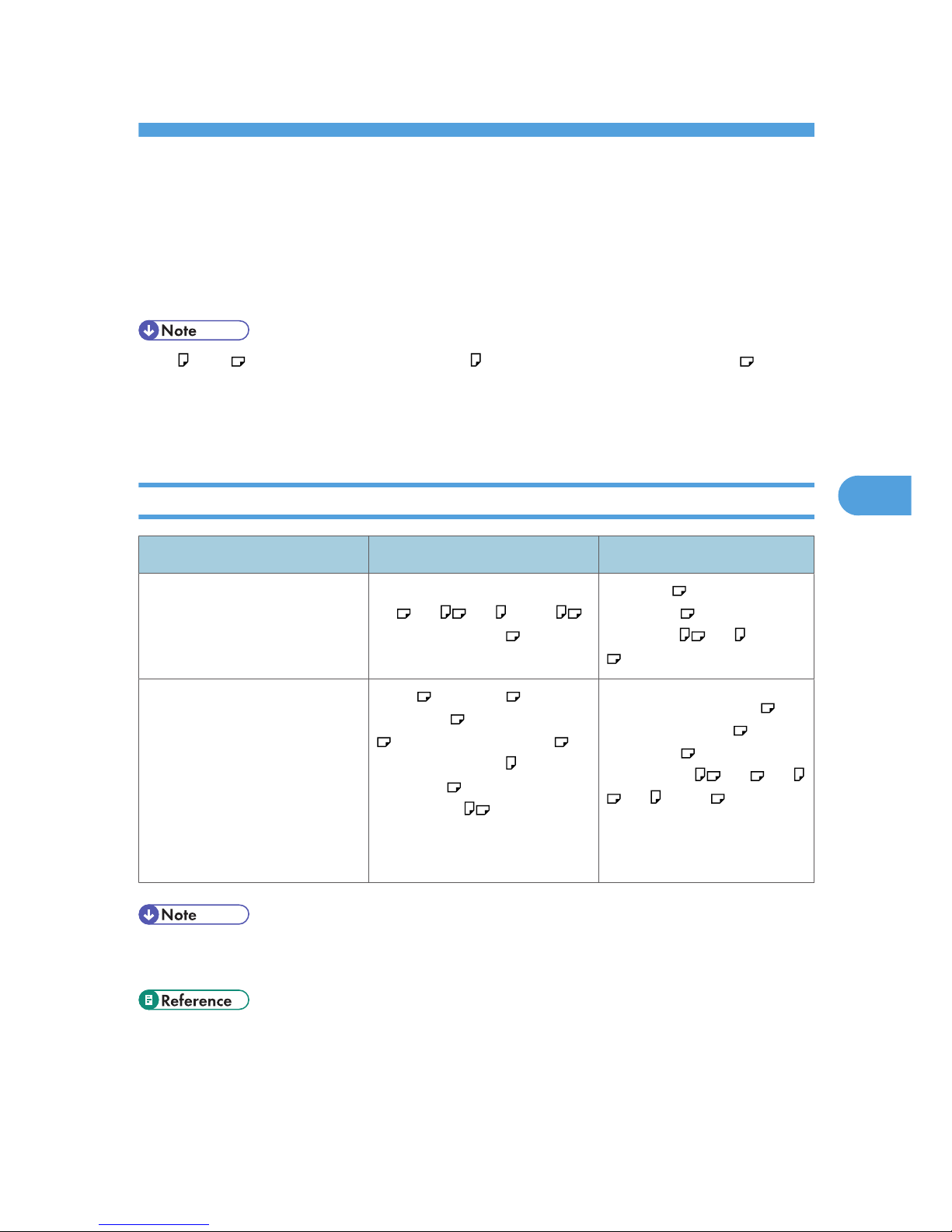
5. Paper and Other Media
Supported Paper for Each Tray
This section describes the paper size, feed direction, and the maximum amount of paper that can be loaded
into each paper tray in this printer.
• " " and " " indicate paper feeding directions: indicates short-edge feed direction, and indicates
long-edge feed direction.
• Be careful of the paper feed direction when loading paper. The direction is determined for each paper
size.
500-sheet Paper Trays
Metric version Imperial version
Paper sizes selected
automatically
A3 , A4 , A5 , B5 JIS ,
81/2" × 11" (Letter)
11" × 17" , 81/2" ×
14" (Legal) , 81/2" ×
11" (Letter) , A5 , B5 JIS
Paper sizes requiring manual
setting
B4 JIS , 11" × 17" , 81/2" ×
14" (Legal) , 8" × 13" (F/GL)
, 81/2" × 13" (Foolscap) ,
81/2" × 11" (Letter) , 81/4" ×
13" (Folio) , 71/4" × 101/
2"
(Executive)
Custom size: 182 to 297 mm in
width, 148 to 432 mm in length
81/2" × 13" (Foolscap) ,
81/4" × 13" (Folio) , 8" ×
13" (F/GL) , 71/4" × 101/
2
" (Executive) , A3 , A4
, A5 , B4 JIS
Custom size: 7.17" to 11.69" in
width, 5.83" to 17.00" in length
• When using paper whose sizes are not automatically selected, select the paper size manually using
the control panel. See "Loading Paper".
• p.89 "Loading Paper"
77
5
Page 80
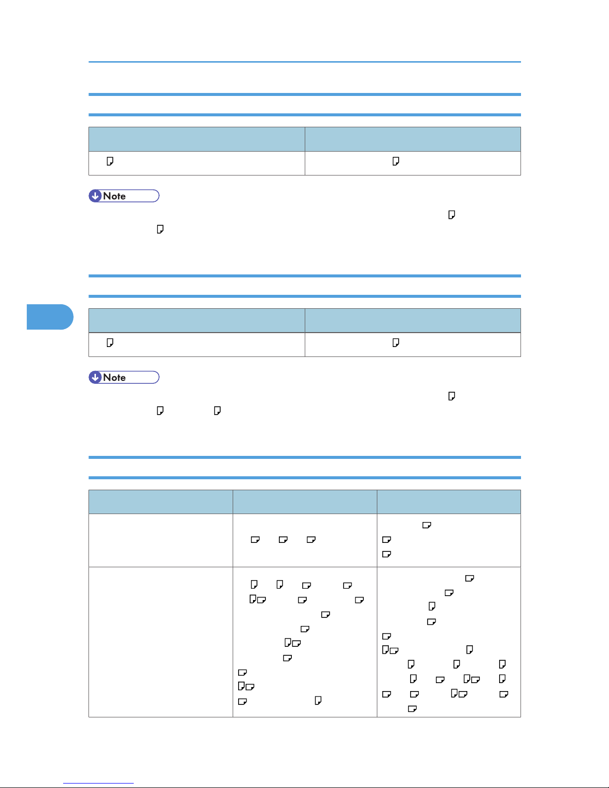
2000-sheet Paper Feed Unit
Metric version Imperial version
A4 81/2" × 11" (Letter)
• The paper tray guides are fixed. However, you can switch the setting between A4 and 81/2" ×
11" (Letter) . If you wish to use a paper size other than the default, contact your sales or service
representative.
1200-sheet Paper Feed Unit
Metric version Imperial version
A4 81/2" × 11" (Letter)
• The paper tray guides are fixed. However, you can switch the setting between A4 , 81/2" ×
11" (Letter) , and B5 JIS . If you wish to use a paper size other than the default, contact your sales
or service representative.
Bypass Tray
Metric version Imperial version
Paper sizes selected
automatically
A3 , A4 , A5
11" × 17" , 81/2" × 11" (Letter)
, 51/2" × 81/2" (Half Letter)
Paper sizes requiring manual
setting
A4 , A5 , A6 , B4 JIS , B5
JIS , B6 JIS , 11" × 17" ,
81/2" × 14" (Legal) , 81/2" ×
13" (Foolscap) , 81/2" ×
11" (Letter) , 81/4" ×
13" (Folio) , 8" × 13" (F/GL)
, 71/4" × 101/2" (Executive)
, 51/2" × 81/2" (Half Letter)
, 41/8" × 91/2" , 37/8" ×
81/2" × 14" (Legal) , 81/2" ×
13" (Foolscap) , 81/2" ×
11" (Letter) , 81/4" ×
13" (Folio) , 8" × 13" (F/GL)
, 71/4" × 101/2" (Executive)
, 41/8" × 91/2" , 37/8" ×
71/2" , C5 Env. , C6 Env. ,
DL Env , A3 , A4 , A5
, A6 , B5 JIS , B4 JIS ,
B6 JIS
5. Paper and Other Media
78
5
Page 81
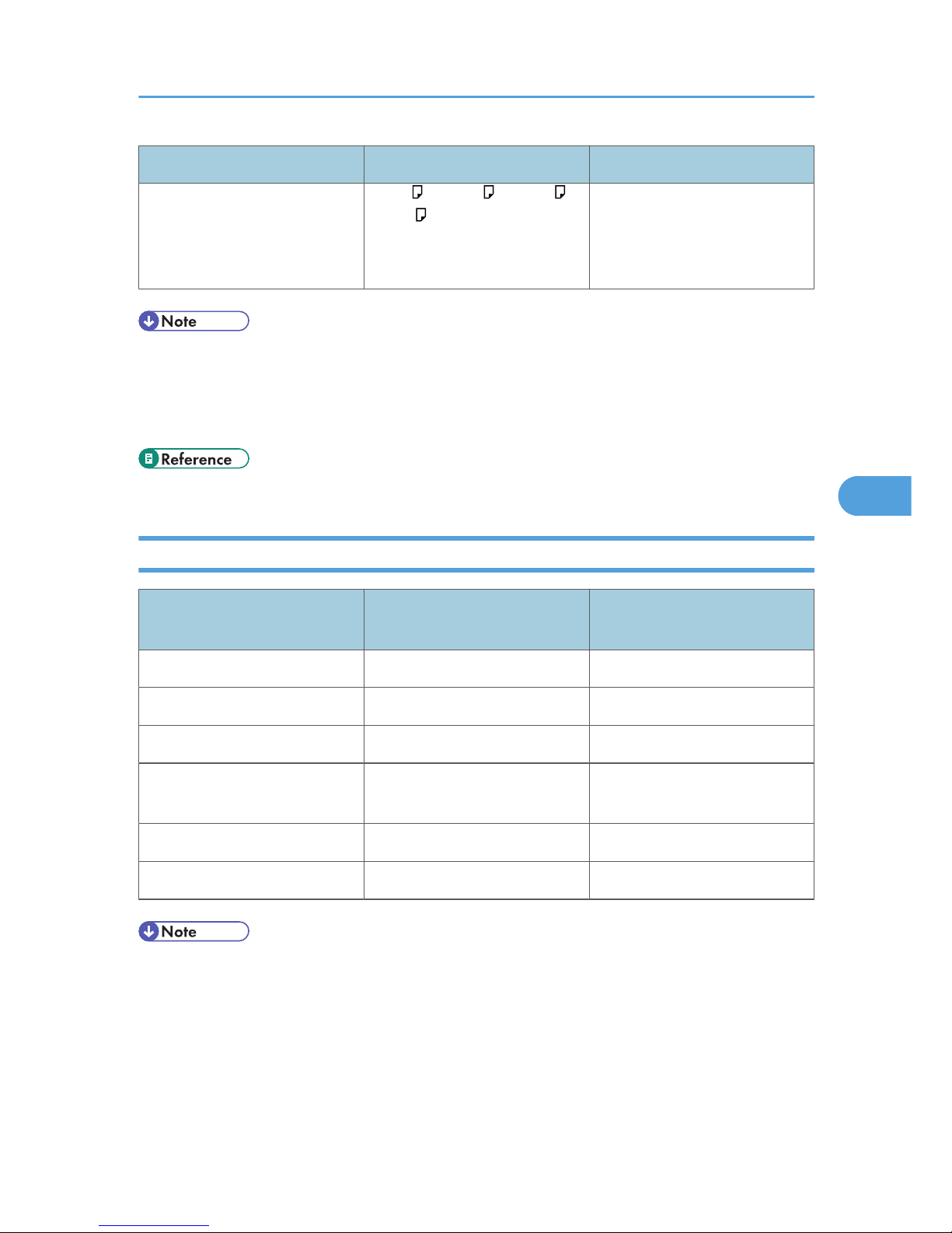
Metric version Imperial version
71/2" , C5 Env. , C6 Env. ,
DL Env
Custom size: 90 to 305 mm in
width, 148 to 600 mm in length
Custom size: 3.55" to 12.00" in
width, 5.83" to 23.62" in length
• Print quality may not be guaranteed for custom size paper that is wider than 297 mm (11.69 inches)
in width or longer than 433 mm (17.05 inches) in length.
• When using paper whose sizes are not automatically selected, select the paper size manually using
the control panel. See "Loading Paper".
• p.89 "Loading Paper"
Paper Weight and Capacity
Tray Supported paper weight
Supported capacity (Plain
paper)
Tray 1 60 to 216 g/m2 (16 to 57 lb.) 550 sheets (80 g/m2, 20 lb.)
Tray 2 60 to 216 g/m2 (16 to 57 lb.) 550 sheets (80 g/m2, 20 lb.)
1000-sheet paper feed unit 60 to 216 g/m2 (16 to 57 lb.) 550 sheets × 2 (80 g/m2, 20 lb.)
2000-sheet paper feed unit 60 to 216 g/m2 (16 to 57 lb.)
1000 sheets × 2 (80 g/m2, 20
lb.)
1200-sheet paper feed unit 60 to 216 g/m2 (16 to 57 lb.) 1200 sheet (80 g/m2, 20 lb.)
Bypass tray 52 to 216 g/m2 (14 to 57 lb.) 100 sheets (80 g/m2, 20 lb.)
• Do not load the paper so that the top of the stack exceeds the under limit mark inside the tray.
Supported Paper for Each Tray
79
5
Page 82
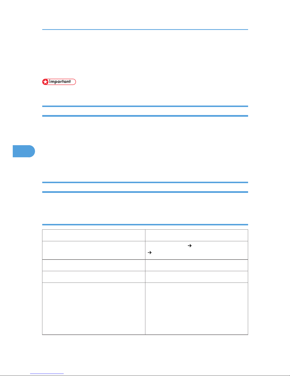
Paper Recommendations
This section describes loading and storing paper, details of each type of paper, and the printable area.
Configure the settings depending on the type of paper you are using.
• Print quality cannot always be guaranteed for all types of paper that are sold at stores.
Storing Paper
Take care when storing paper. Improperly stored paper might result in poor print quality, paper misfeeds,
or printer damage. Recommendations are as follows:
• Avoid storing paper in humid areas.
• Avoid exposing paper to direct sunlight.
• Store on a flat surface.
• Keep paper in its original package until time to use it.
Types of Paper and Other Media
This section describes the types of paper and required settings.
Plain paper
Paper thickness 60 to 81g/m2 (14 to 21lb.)
Printer setup
Select [Paper Input] [Paper Type: (tray name)]
[Plain Paper].
Printer driver setup Select [Plain] in [Paper Type].
Supported paper feeding tray Any input tray can be used.
Paper capacity
• Tray 1, 2: 550
• Tray 3: 550 (1000-sheet paper feed unit) or
2000 (2000-sheet paper feed unit)
• Tray 4: 550
• LCT: 1200
• Bypass tray: 100
5. Paper and Other Media
80
5
Page 83
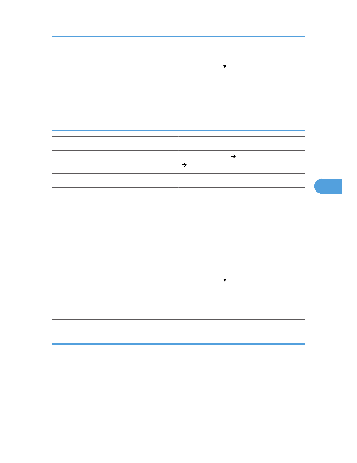
Make sure paper is not stacked higher than the
upper limit mark ( ) inside the tray. When using the
bypass tray, make sure paper is not stacked higher
than the paper guides inside it.
Duplex printing Supported
Middle Thick
Paper thickness 82 to 105g/m2 (21 to 28lb.)
Printer setup
Select [Paper Input] [Paper Type: (tray name)]
[Middle Thick].
Printer driver setup Select [Middle Thick] in [Paper Type].
Supported paper feeding tray Any input tray can be used.
Paper capacity
• Tray 1, 2: 550
• Tray 3: 550 (1000-sheet paper feed unit) or
2000 (2000-sheet paper feed unit)
• Tray 4: 550
• LCT: 1200
• Bypass tray: 100
Make sure paper is not stacked higher than the
upper limit mark ( ) inside the tray. When using the
bypass tray, make sure paper is not stacked higher
than the paper guides inside it.
Duplex printing Supported
Thick paper
Paper thickness
106 to 216 g/m2 (28 to 58 lb.)
• [Thick Paper 1]: 106 to 160 g/m2 (28 to 45
lb.)
• [Thick Paper 2]: 161 to 216 g/m2 (45 to 57
lb.)
• [Thick Paper 3]: 161 to 216 g/m2 (45 to 57
lb.)
Paper Recommendations
81
5
Page 84

Printer setup
Select [Paper Input] [Paper Type: (tray name)]
[Thick Paper 1].
Select [Paper Input] [Paper Type: Bypass Tray]
[Thick Paper 2] to [Thick Paper 3]
Printer driver setup
Select [Thick Paper 1] to [Thick Paper 3] in [Paper
Type].
Supported paper feeding tray
[Thick Paper 1]: Any input tray can be used.
[Thick Paper 2] and [Thick Paper 3]: Bypass tray
Paper capacity
• Bypass tray: 40 for [Thick Paper 1], 20 for
[Thick Paper 2] and [Thick Paper 3]
Make sure paper is not stacked higher than the
upper limit mark ( ) inside the tray. When using the
bypass tray, make sure paper is not stacked higher
than the paper guides inside it.
Duplex printing
• [Thick Paper 1]: Supported
• [Thick Paper 2,] [Thick Paper 3]: Not
supported
Additional cautions
• Print speed is slightly slower than when using
plain paper.
• When printing on the reverse side of thick
paper that is already printed on, select [Paper
Type: (tray name)] [Thick 1:Dup.Back1] to
[Thick 1:Dup.Back3] using control panel or
printer driver.
Thin paper
Paper thickness 52 to 60 g/m2 (14 to 16lb.)
Printer setup
Select [Paper Input] [Paper Type: (tray name)]
[Thin Paper].
Printer driver setup Select [Thin Paper] in [Paper Type].
Supported paper feeding tray Bypass tray
Paper capacity
Make sure paper is not stacked higher than the
upper limit mark ( ) inside the tray. When using the
5. Paper and Other Media
82
5
Page 85
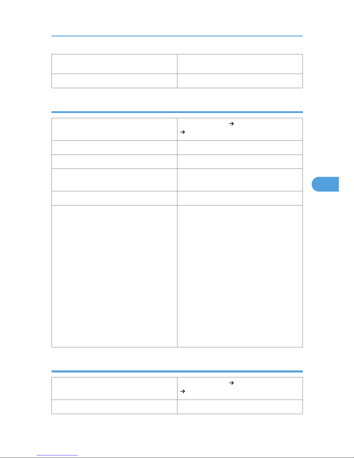
bypass tray, make sure paper is not stacked higher
than the paper guides inside it.
Duplex printing Not supported
OHP transparencies
Printer setup
Select [Paper Input] [Paper Type: Bypass Tray]
[OHP transparencies].
Printer driver setup Select [OHP transparencies] in [Paper Type].
Supported paper feeding tray Bypass tray
Paper capacity
Make sure paper is not stacked higher than the
paper guides inside the bypass tray.
Duplex printing Not supported
Additional cautions
• When loading OHP transparencies, take care
not to load them upside down. Doing so may
cause a malfunction.
• It is recommended to place one sheet at a
time.
• Make sure to fan OHP transparencies every
time before printing. Leaving OHP
transparencies loaded in the paper tray may
cause them to stick together and result in a
misfeed.
• If multiple OHP transparencies are fed at the
same time, load them one by one.
• When printing on OHP transparencies,
remove the transparencies one by one as they
are output.
Letterhead
Printer setup
Select [Paper Input] [Paper Type: (tray name)]
[Letterhead].
Printer driver setup Select [Letterhead] in [Paper Type].
Paper Recommendations
83
5
Page 86
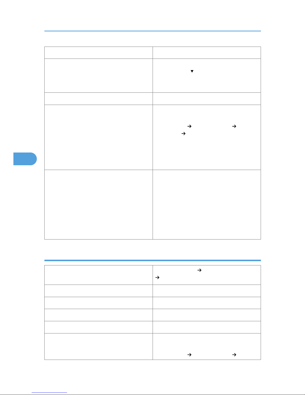
Supported paper feeding tray Any input tray can be used.
Paper capacity
Make sure paper is not stacked higher than the
upper limit mark ( ) inside the tray. When using the
bypass tray, make sure paper is not stacked higher
than the paper guides inside it.
Duplex printing Supported
Letterhead setup
Default: [Letterhead 1]
If the print quality needs to be improved, select
[Maintenance] [General Settings]
[Letterhead] [Letterhead 1] to [Letterhead 3] to
change the setting value to a different number
depending on the paper thickness that you are
using. High numbered settings allow thicker paper
to be used, but are printed more slowly.
Additional cautions
• Paper tray:
When loading paper vertically, make sure to
set its header to the back; when horizontally,
make sure to set its header to the left.
• Bypass tray:
When loading paper vertically, make sure to
set its header to the back; when horizontally,
make sure to set its header to the right.
Label paper
Printer setup
Select [Paper Input] [Paper Type: Bypass Tray]
[Labels].
Printer driver setup Select [Label Paper] in [Paper Type].
Supported paper feeding tray Bypass tray
Paper capacity 1
Duplex printing Not supported
Label paper setup
Default: [Labels 1]
If the print quality needs to be improved, select
[Maintenance] [General Settings] [Labels]
5. Paper and Other Media
84
5
Page 87
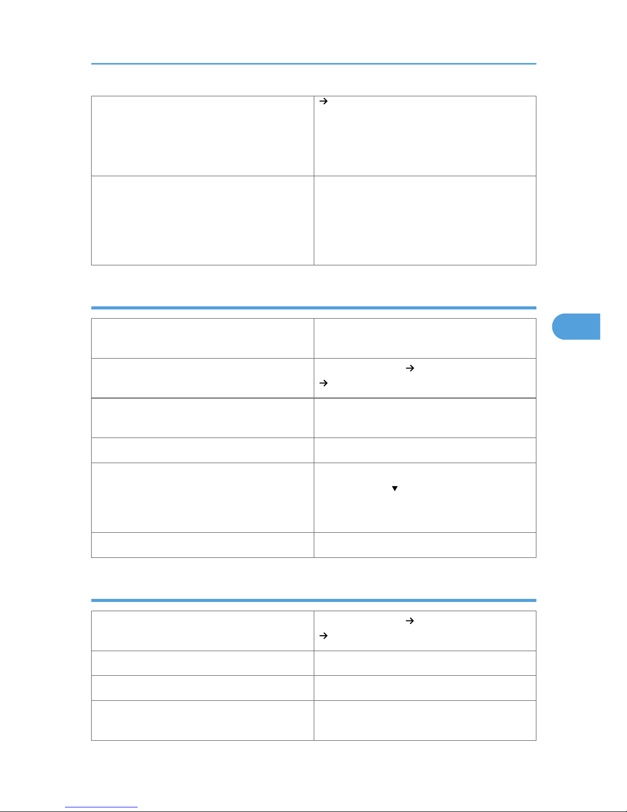
[Labels 1] to [Labels 3] to change the setting
value to a different number depending on the
paper thickness that you are using. High numbered
settings allow thicker paper to be used, but are
printed more slowly.
Additional cautions
• Print speed is slightly slower than when using
plain paper.
• Shuffle paper before loading the stack onto
the tray, so multiple sheets are not fed in
together.
Special paper
Special paper standard
When you cannot print successfully with other
paper type settings, set special paper.
Printer setup
Select [Paper Input] [Paper Type: (tray name)]
[Special Paper 1] to [Special Paper 3].
Printer driver setup
Select [Special Paper 1] to [Special Paper 3] in
[Paper Type].
Supported paper feeding tray Any input tray can be used.
Paper capacity
Make sure paper is not stacked higher than the
upper limit mark ( ) inside the tray. When using the
bypass tray, make sure paper is not stacked higher
than the paper guides inside it.
Duplex printing Supported
Envelopes
Printer setup
Select [Paper Input] [Paper Type: Bypass Tray ]
[Envelope].
Printer driver setup Select [Envelope Settings] in [Paper Type].
Supported paper feeding tray Bypass tray
Paper capacity
Make sure paper is not stacked higher than the
paper guides inside the bypass tray.
Paper Recommendations
85
5
Page 88

Duplex printing Not supported
Envelope setup
Default: [Envelope 1]
If the print quality needs to be improved, select a
paper type that is appropriate for the thickness of
the envelope you are using. Select [Maintenance]
[General Settings] [Envelope] [Envelope
1] to [Envelope 3].
High numbered settings allow thicker paper to be
used, but are printed more slowly.
Additional cautions
• Load envelopes with the print side down, and
the open end of the envelope facing out from
the printer.
• When printing on envelopes, set the envelope
size using the printer driver or control panel.
See “Loading Paper” for details.
• Before loading envelopes, remove any air
inside and make sure all edges are sharply
creased. If envelopes are curled, straighten
them before loading.
• If envelopes are curled when they are output,
straighten them by rubbing.
• Depending on the printing environment,
envelopes may be output with the edges
wrinkled, with toner marks on the back, or
blurred. In addition, when printing solid black
areas, streaks may appear where two
envelopes touch.
• Depending on the type of envelope or printing
environment, envelopes might be output
creased or printed improperly. In such cases,
try changing the loading orientation.
• p.89 "Loading Paper"
5. Paper and Other Media
86
5
Page 89

Paper Not Supported by This Printer
• Do not use the following types of paper:
• Ink-jet printer paper
• GelJet special paper
• Bent, folded, or creased paper
• Curled or twisted paper
• Wet paper
• Paper that is dry enough to emit static electricity
• Paper that has already been printed on
Misprints are especially likely when using paper printed on by printers other than a laser printer
(e.g. monochrome and color copiers, ink-jet printers, etc.) Refrain from printing on the side on
which nothing is printed.
• Surface-processed paper (excluding specified paper)
• Special paper, such as thermal paper and carbon paper
• Paper whose weight is heavier or lighter than the limitation
• Perforated paper
• Adhesive label paper on which glue or base paper is exposed
• Paper with clips or staples
• Even if paper is adequate for the printer, poorly stored paper can cause paper misfeeds, print quality
degradation, or malfunctions.
Print Area
This section describes the area of a page that is available for printing.
The following diagram shows the print area for this printer.
Paper Recommendations
87
5
Page 90
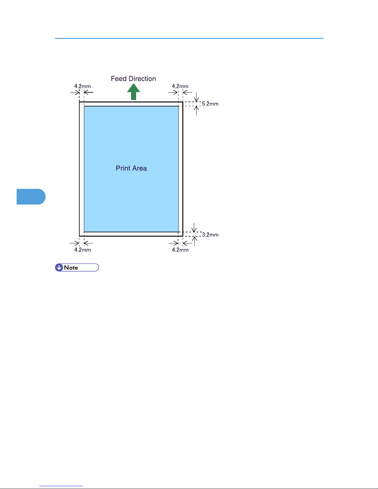
Paper
BEK207S
• While printing may be possible on the entire page depending on the settings of the printer driver or
print conditions, the quality cannot be guaranteed for the 5.2 mm (0.21 inches) margin of the upper
side, the 4.2 mm (0.17 inches) margins of the right and left sides, and the 3.2 mm (0.13 inches)
margin of the lower side.
• The print area of long paper is restricted to 600 mm (23.62 inches) long in the feed direction.
5. Paper and Other Media
88
5
Page 91
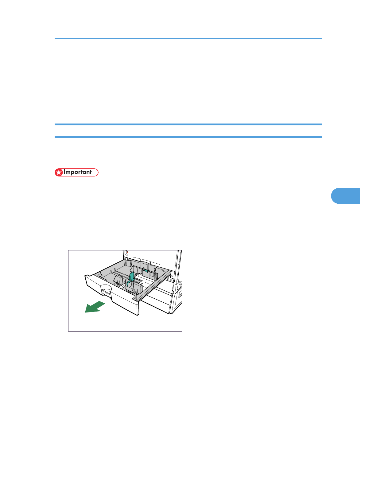
Loading Paper
This section describes how to load paper into the paper tray or onto the bypass tray.
Do not add paper to a tray before it runs out of paper. If you do so, multiple sheets of paper may be fed
at one time, which results in a paper jam.
500-sheet Paper Feed Trays
The following example explains how to load paper into paper trays, and how to change paper size.
The same procedure can be used for all trays. Tray 1 is used as an example.
• Make sure paper is not stacked higher than the upper limit mark inside the paper tray. Paper misfeeds
might occur.
• Do not mix different types of paper in the same paper tray.
• During printing, do not open or close the printer covers or bypass tray, or pull out or push in the paper
tray.
1. Carefully pull out the paper tray until it stops.
BEK246S
When printing using the bypass tray, do not pull out the paper tray.
Loading Paper
89
5
Page 92
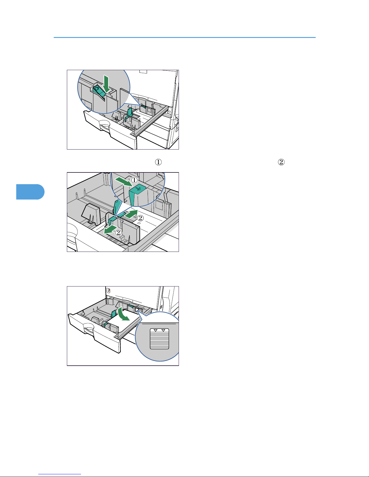
2. Unlock the side guides.
BEK097S
3. Pinch the clip on the side guide ( ), and match the guides to the paper size ( ).
BEK001S
4. Align and load paper in the tray with the print side up.
You can load up to 550 sheets in each tray.
BEK098S
5. Paper and Other Media
90
5
Page 93
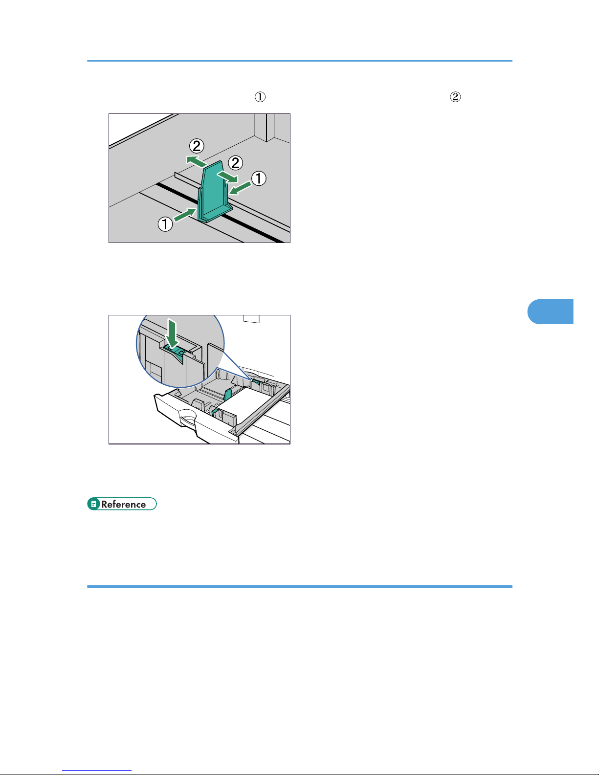
5. Pinch the clips on the end guide ( ), and match the guide to the paper size ( ).
BEK191S
Confirm that there are no gaps between the paper and paper guides. If there are gaps, adjust the
guides.
6. Lock the side guides.
BEK099S
7. Push the paper tray carefully into the printer until it stops.
If you push the tray forcefully, the paper guides might move.
• For details about types of paper supported by this printer, see p.77 "Supported Paper for Each
Tray".
Setting paper size not selected automatically
Set the paper size using the control panel when loading paper whose size cannot be selected automatically.
Loading Paper
91
5
Page 94
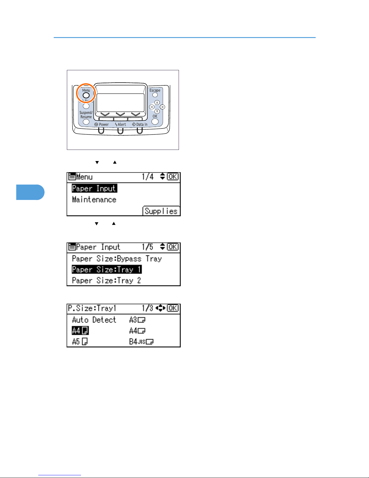
1. Press the [Menu] key.
BEK204S
2. Press the [ ] or [ ] key to select [Paper Input], and then press the [OK] key.
3. Press the [ ] or [ ] key to select [Paper Size:( tray name)], and then press the [OK] key. For
example, [Paper Size: Tray 1] is selected for Tray 1 as shown.
4. Select the paper size you want to set using the scroll keys, and then press the [OK ] key.
About two seconds later, the display returns to the [Paper Input] screen.
5. Press the [Menu] key.
The display returns to the initial screen. This completes the paper size setting.
If you want to return the settings to [Auto Detect], load paper into the paper tray and follow the
procedure below.
5. Paper and Other Media
92
5
Page 95
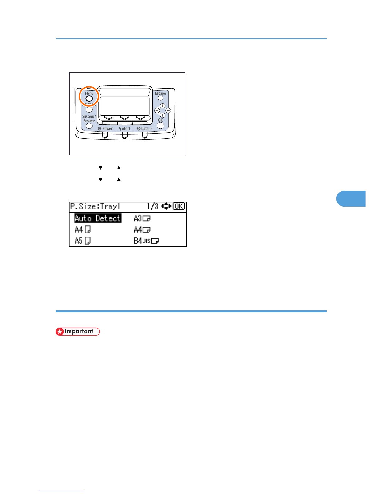
6. Press the [Menu] key.
BEK204S
7. Press the [ ] or [ ] key to select [Paper Input], and then press the [OK] key.
8. Press the [ ] or [ ] key to select [Paper Size: Tray 1], and then press the [OK] key.
9. Select [Auto Detect] using the scroll keys, and then press the [OK] key.
About two seconds later, the display returns to the [Paper Input] screen.
10. Press the [Menu] key.
The display returns to the initial screen.
Setting custom size paper
Set the custom paper size using the control panel when loading custom size paper.
• When printing on custom size paper, specify the paper size using the control panel or printer driver.
• The custom size paper selected using the printer driver overrides that selected using the control panel.
Do not configure settings using the control panel if you have already configured settings using the
printer driver. However, when printing with a printer driver other than the RPCS printer driver, you
must configure the settings using the control panel.
• The following is the range of paper size that can be set as custom size: 182 to 297 mm (7.17 to
11.69 inches) in width and 148 to 432 mm (5.83 to 17.00 inches) in length.
• The printer cannot print to custom size paper from applications that do not support custom size paper.
Loading Paper
93
5
Page 96
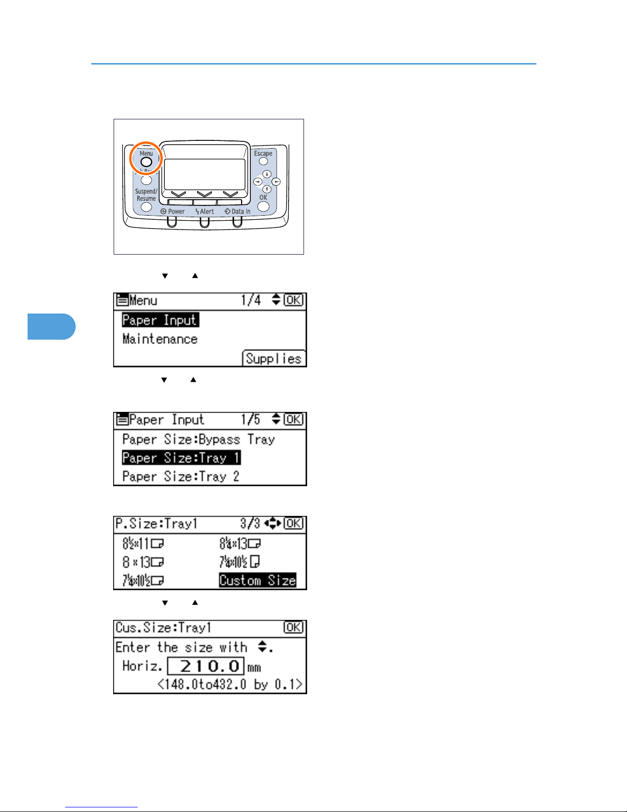
1. Press the [Menu] key.
BEK204S
2. Press the [ ] or [ ] key to select [Paper Input], and then press the [OK] key.
3. Press the [ ] or [ ] key to select [Paper Size: (tray name)], and then press the [OK] key. For
example, [Paper Size: Tray 1] is selected for Tray 1 as shown.
4. Select [Custom Size] using the scroll keys, and then press the [OK] key.
5. Press the [ ] or [ ] key to enter the horizontal value, and then press the [OK] key.
If you press and hold the key, the value increases/decreases by 1 or 10 mm.
5. Paper and Other Media
94
5
Page 97
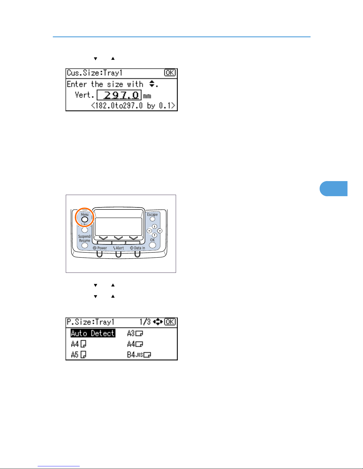
6. Press the [ ] or [ ] key to enter the vertical value, and then press the [OK] key.
If you press and hold the key, the value increases/decreases by 1 or 10 mm.
The settings appear and about two seconds later, the display returns to the [Paper Input] screen.
7. Press the [Menu] key.
The display returns to the initial screen.
If you want to return the settings to [Auto Detect], load paper into the paper tray, and follow the
procedure below.
8. Press the [Menu] key.
BEK204S
9. Press the [ ] or [ ] key to select [Paper Input], and then press the [OK] key.
10. Press the [ ] or [ ] key to select [Paper Size: Tray 1], and then press the [OK] key.
11. Select [Auto Detect] using the scroll keys, and then press the [OK] key.
About two seconds later, the display returns to the [Paper Input] screen.
12. Press the [Menu] key.
The display returns to the initial screen.
Loading Paper
95
5
Page 98
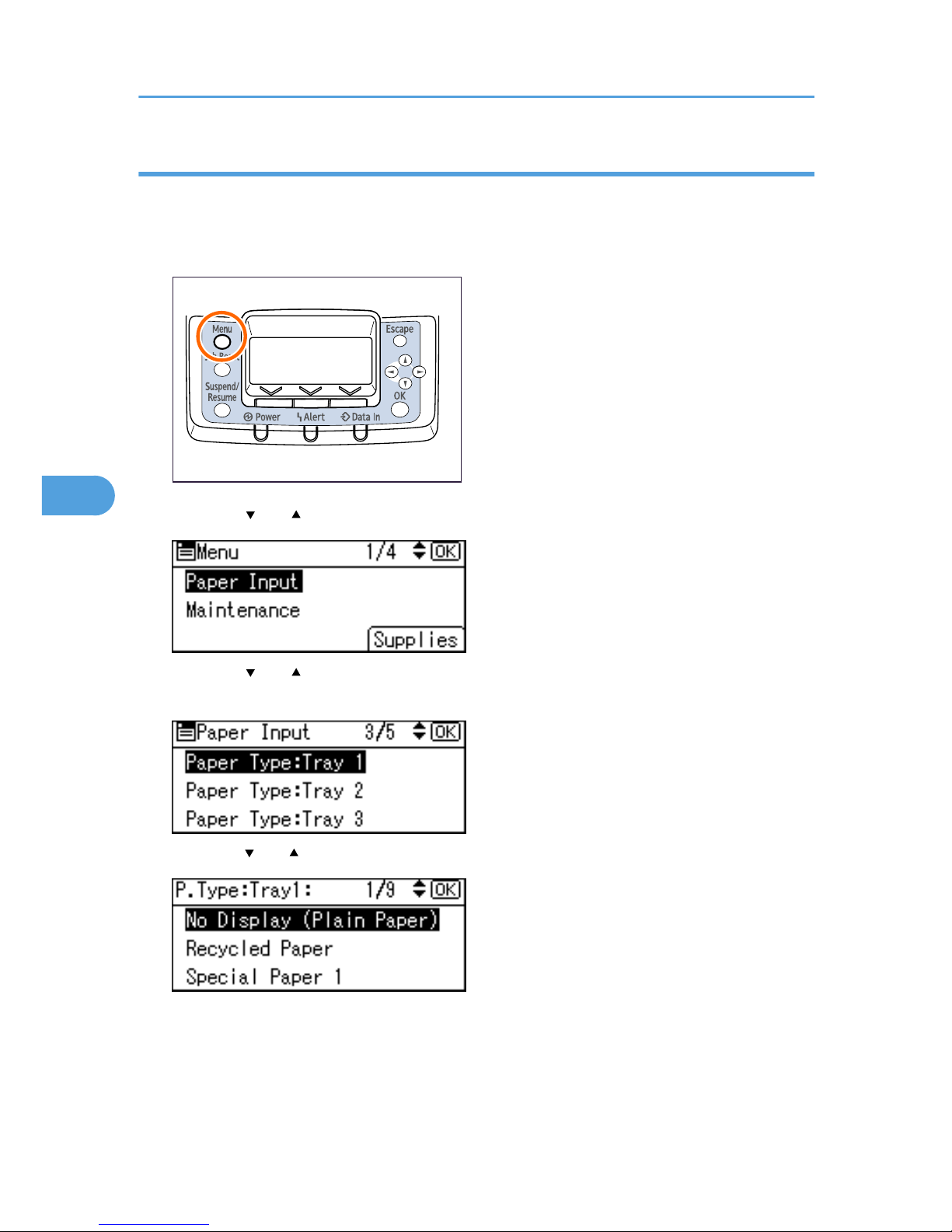
Specifying a paper type
This section describes how to specify a paper type. You can improve printer performance by selecting the
optimum paper type for the tray.
1. Press the [Menu] key.
BEK204S
2. Press the [ ] or [ ] key to select [Paper Input], and then press the [OK] key.
3. Press the [ ] or [ ] key to select [Paper Type: (tray name)], and then press the [OK] key.
For example, [Paper Type: Tray 1] is selected for Tray 1 as shown.
4. Press the [ ] or [ ] key to select the paper type that is loaded, and then press the [OK] key.
About two seconds later, the display returns to the [Paper Input] screen.
5. Press the [Menu] key.
The display returns to the initial screen.
5. Paper and Other Media
96
5
Page 99
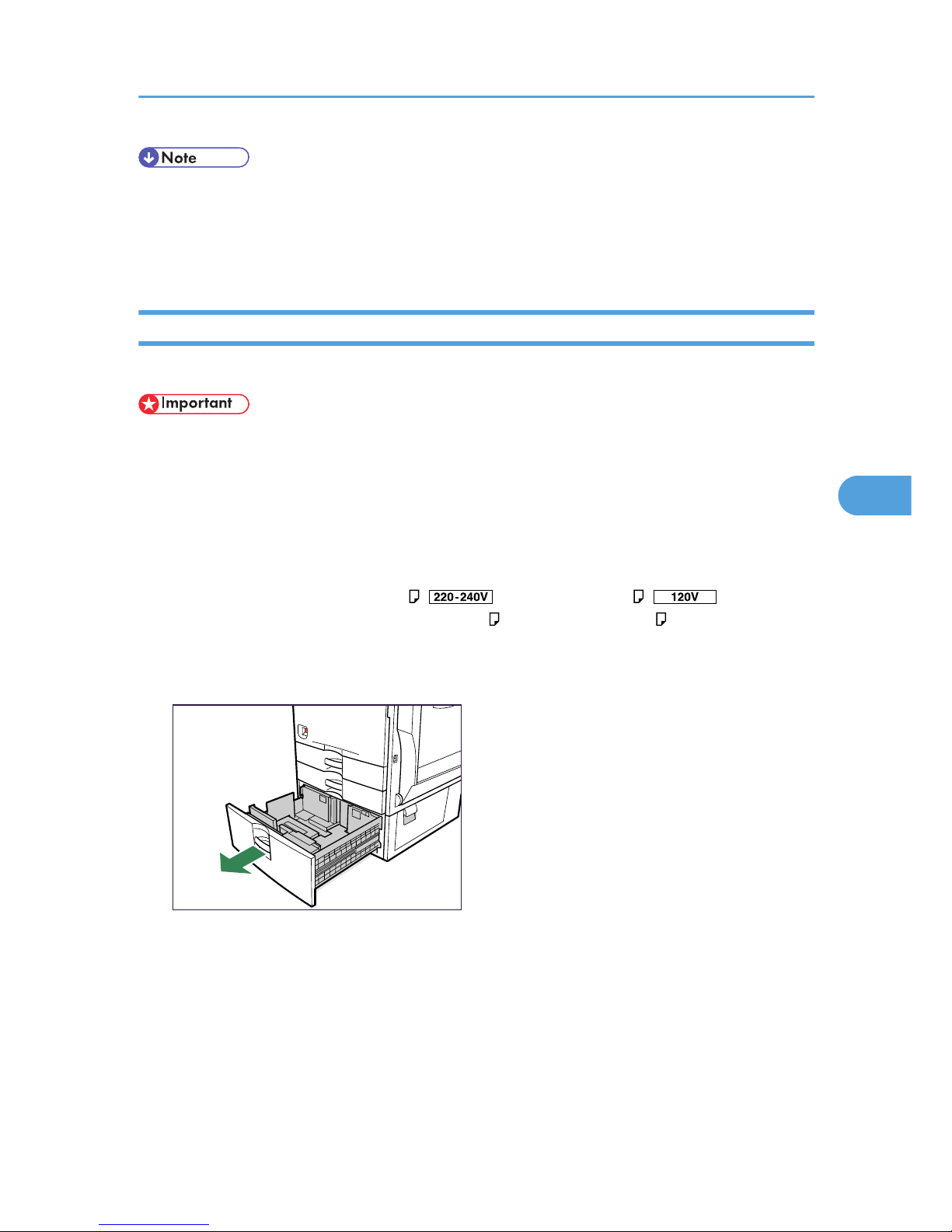
• The tray does not support envelopes and OHP transparencies.
• Duplex printing is not supported for the following paper types: labels, thin paper, cardstock, thick
paper ([Thick Paper 2], [Thick Paper 3]), the reverse side of thick paper ([Thick 2:Dup.Back], [Thick
3:Dup.Back]).
2000-sheet Paper Feed Unit
This section describes how to load paper into the 2000-sheet paper feed unit (tray 3).
• Make sure paper is not stacked higher than the upper limit mark inside the paper tray. Paper misfeeds
might occur.
• Do not mix different types of paper in the same paper tray.
• During printing, do not open or close the printer covers, bypass tray, or paper tray.
• Make sure to align paper and push it neatly to both sides of the tray. If you do not, it can cause a
paper misfeed.
• The paper tray guides are fixed at A4
( ) or 81/2 × 11 (Letter) ( ) size positions.
However, you can switch the setting between A4 and 8 1/2 × 11 (Letter) . If you wish to use a
paper size other than the default, contact your sales or service representative.
1. Carefully pull out the paper tray until it stops.
BEK247S
When printing using the bypass tray, do not pull out the paper tray.
2. Align and load paper into the right and left sides with the print side up.
You can load up to 1000 sheets in each side.
Loading Paper
97
5
Page 100
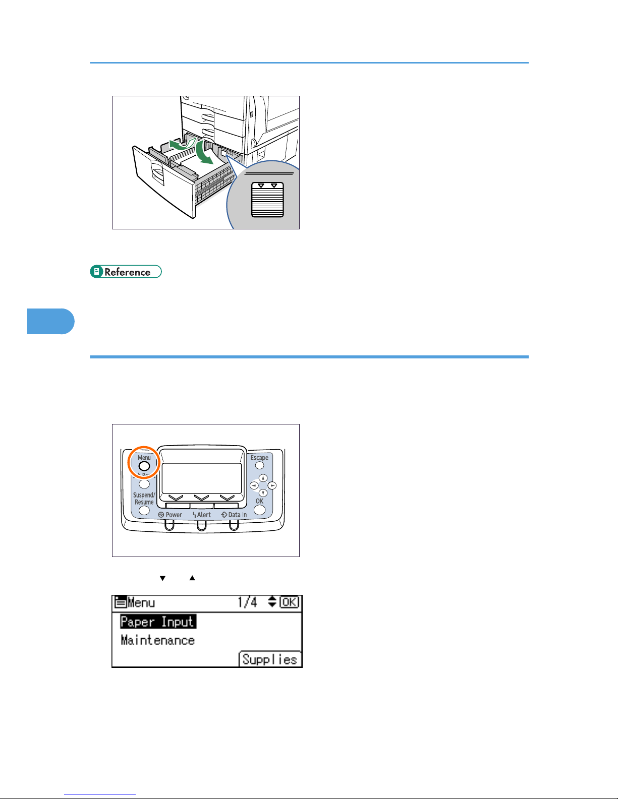
BEK100S
3. Push the paper tray carefully into the printer until it stops.
• For details about types of paper supported by this printer, see p.77 "Supported Paper for Each
Tray".
Specifying a paper type
This section describes how to specify a paper type. You can improve printer performance by selecting the
optimum paper type for the tray.
1. Press the [Menu] key.
BEK204S
2. Press the [ ] or [ ] key to select [Paper Input], and then press the [OK] key.
5. Paper and Other Media
98
5
 Loading...