

Page 1

G160 Service Manual 23-Feb-06
Model G-P2
Machine Code: G160
SERVICE MANUAL
Copyright Ricoh Company, LTD©
Feb. 24th, 2006
Subject to change
Page 2

G160 Service Manual 23-Feb-06
ii
Read This First
Safety Notices
Important Safety Notices
Prevention of Physical Injury
1. Before disassembling or assembling parts of the printer and peripherals, make
sure that the printer power cord is unplugged.
2. The wall outlet should be near the printer and easily accessible.
3. If any adjustment or operation check has to be made with exterior covers off or
open while the main switch is turned on, keep hands away from electrified or
mechanically driven components.
4. The printer drives some of its components when it completes the warm-up period.
Be careful to keep hands away from the mechanical and electrical components as
the printer starts operation.
5. The inside and the metal parts of the fusing unit become extremely hot while the
printer is operating. Be careful to avoid touching those components with your bare
hands.
Health Safety Conditions
Toner and developer are non-toxic, but if you get either of them in your eyes by accident, it
may cause temporary eye discomfort. Immediately wash eyes with plenty of water. If
unsuccessful, get medical attention.
Observance of Electrical Safety Standards
The printer and its peripherals must be serviced by a customer service representative who
has completed the training course on those models.
Lithium Batteries
Incorrect replacement of lithium battery(s) on the EGB and controller board may pose risk of
explosion. Replace only with the same type or with an equivalent type recommended by the
manufacturer. Discard used batteries in accordance with the manufacturer’s instructions.
Page 3
G160 Service Manual 23-Feb-06
iii
Safety and Ecological Notes for Disposal
1. Do not incinerate toner bottles or used toner. Toner dust may ignite suddenly when
exposed to an open flame.
2. Dispose of used toner, the maintenance unit which includes developer or the
organic photoconductor in accordance with local regulations. (These are non-toxic
supplies.)
3. Dispose of replaced parts in accordance with local regulations.
4. When keeping used lithium batteries in order to dispose of them later, do not put
more than 100 batteries per sealed box. Storing larger numbers or not sealing
them apart may lead to chemical reactions and heat build-up.
LASER SAFETY
The Center for Devices and Radiological Health (CDRH) prohibits the repair of laser-based
optical units in the field. The optical housing unit can only be repaired in a factory or at a
location with the requisite equipment. The laser subsystem is replaceable in the field by a
qualified Customer Engineer. The laser chassis is not repairable in the field. Customer
engineers are therefore directed to return all chassis and laser subsystems to the factory or
service depot when replacement of the optical subsystem is required.
Use of controls, or adjustment, or performance of procedures other than those
specified in this manual may result in hazardous radiation exposure.
Turn off the main switch before attempting any of the procedures in the Laser Optics Housing
Unit section. Laser beams can seriously damage your eyes.
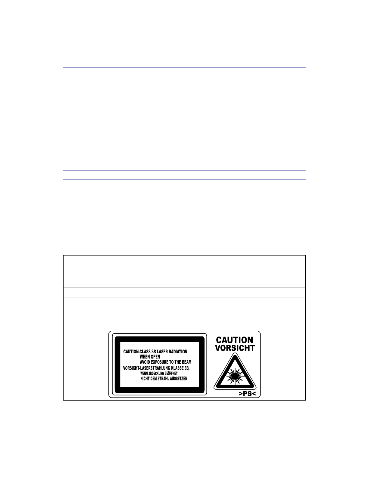
CAUTION MARKING:
Page 4

G160 Service Manual 23-Feb-06
iv
Symbols, Abbreviations, and Trademarks
Symbols and Abbreviations
This manual uses the symbols and abbreviations shown below.
Symbol Meaning
Refer to section number
Clip ring
Screw
Connector
Clamp
SEF Short Edge Feed
LEF Long Edge Feed
Trademarks
Microsoft®, Windows®, and MS-DOS® are registered trademarks of Microsoft Corporation
in the United States and /or other countries.
PostScript® is a registered trademark of Adobe Systems, Incorporated.
PCL® is a registered trademark of Hewlett-Packard Company.
Ethernet® is a registered trademark of Xerox Corporation.
PowerPC® is a registered trademark of International Business Machines Corporation.
Other product names used herein are for identification purposes only and may be trademarks
of their respective companies. We disclaim any and all rights involved with those marks.
Page 5

G160 Service Manual 23-Feb-06
v
Table of Contents
Read This First ..................................................................................................................... ii
Safety Notices................................................................................................................... ii
Important Safety Notices ...............................................................................................
ii
LASER SAFETY............................................................................................................
iii
Symbols, Abbreviations, and Trademarks ........................................................................
iv
Symbols and Abbreviations ..........................................................................................
iv
Trademarks...................................................................................................................
iv
Table of Contents..................................................................................................................
v
Installation Procedure ...........................................................................................................1
Installation Requirements..................................................................................................1
Optional Unit Installation ...................................................................................................
2
Preventive Maintenance .......................................................................................................
3
User Replaceable Items.................................................................................................... 3
Service Maintenance.........................................................................................................
4
Recommended Cleaning Procedure..............................................................................
4
Replacement And Adjustment...............................................................................................
5
Before You Start ................................................................................................................ 5
Laser Optics ......................................................................................................................
6
Caution Decal Locations................................................................................................
6
LD Unit...........................................................................................................................
7
Fusing .............................................................................................................................
10
Thermistor and Thermostat .........................................................................................
10
Electrical Components ....................................................................................................
13
Controller Board ..........................................................................................................
13
Installing the new NVRAM ...........................................................................................
14
Troubleshooting ..................................................................................................................
15
Process Control Results.................................................................................................. 15
Service Call Conditions ...................................................................................................
17
Summary .....................................................................................................................
17
SC Code Descriptions .................................................................................................
17
Troubleshooting Guide....................................................................................................
46
Blank Print ...................................................................................................................
46
All-black Print...............................................................................................................
46
Missing CMY Color......................................................................................................
46
Page 6

G160 Service Manual 23-Feb-06
vi
Light Print ....................................................................................................................47
Repeated Spots or Lines on Prints ..............................................................................
47
Dark Vertical Line on Prints .........................................................................................
48
White Horizontal Lines or Bands .................................................................................
48
Missing Parts of Images ..............................................................................................
49
Dirty Background .........................................................................................................
49
Partial CMY Color Dots................................................................................................
49
Dark Irregular Streaks on Prints...................................................................................
49
CMY Color Irregular Streaks........................................................................................
50
Ghosting ......................................................................................................................
50
Unfused or Partially Fused Prints ................................................................................
50
Image Skew.................................................................................................................
51
Background Stain ........................................................................................................
51
No Printing on Paper Edge..........................................................................................
51
Image not centered when it should be.........................................................................
52
Electrical Component Defects .........................................................................................
53
Sensors .......................................................................................................................
53
Blown Fuse Conditions ...................................................................................................
57
Power Supply Unit .......................................................................................................
57
IOB ..............................................................................................................................
57
LEDs ...............................................................................................................................
58
Controller .....................................................................................................................
58
Service Tables ....................................................................................................................
59
Service Program Mode ...................................................................................................59
Service Mode Operation..............................................................................................
59
Remarks ......................................................................................................................
60
Bit Switch Programming ..............................................................................................
62
Service Mode Table.........................................................................................................
64
Controller Service Mode ..............................................................................................
64
Engine Service Mode ..................................................................................................
68
Input Check Table......................................................................................................
216
Output Check Table ...................................................................................................
220
Firmware Update...........................................................................................................
223
Types of Firmware.....................................................................................................
223
Precautions................................................................................................................
223
SD Card Application Move ............................................................................................
224
Page 7

G160 Service Manual 23-Feb-06
vii
Overview....................................................................................................................224
Move Exec.................................................................................................................
224
Undo Exec .................................................................................................................
225
Keeping the SD Card.................................................................................................
226
Detailed Section Descriptions...........................................................................................
227
Beforehand.................................................................................................................... 227
Overview .......................................................................................................................
228
Component Layout ....................................................................................................
228
Board Structure..........................................................................................................
229
Process Control.............................................................................................................
232
Overview....................................................................................................................
232
Potential Control ........................................................................................................
232
Toner Supply Control .................................................................................................
235
Toner Near End/Toner End Detection ........................................................................
237
Developer Initialization...............................................................................................
238
Paper Feed ...................................................................................................................
239
By-pass Tray Feed and Size Detection......................................................................
239
Laser Exposure .............................................................................................................
240
LD Safety Switch .......................................................................................................
240
Automatic Line Position Adjustment ..........................................................................
241
Fusing ...........................................................................................................................
245
Overview....................................................................................................................
245
Fusing Temperature Control ......................................................................................
246
Drive ..........................................................................................................................
249
Controller.......................................................................................................................
250
Overview....................................................................................................................
250
Board Layout .............................................................................................................
252
Specifications....................................................................................................................
253
Specifications ................................................................................................................ 253
General Specifications...............................................................................................
253
Supported Paper Sizes..............................................................................................
256
Software Accessories ................................................................................................
257
Machine Configuration...............................................................................................
259
Page 8

G160 Service Manual 23-Feb-06
1
Installation Procedure
Installation Requirements
The installation procedure for G-P2 (G160/G161) is the same as G-P1 (G104/G105). For
details, refer to the Quick Installation Guide for G-P2 (G160/G161).
Page 9

G160 Service Manual 23-Feb-06
2
Optional Unit Installation
The following options are available for this machine. Refer to the Hardware Guide for how to
install these options:
Paper Tray Unit (G392)
HDD (G395)
IEEE802.11b Interface Unit (Wireless LAN: G813)
IEEE 1284 Interface Board (B679)
Bluetooth Interface Unit (B826)
Gigabit Ethernet Board (G874-01)
VM Card (G874-08)
USB Host Interface Unit (B825)
Data Overwrite Security Unit (G874-21)
PictBridge Interface (G874-19)
128 MB DIMM (B584)
256 MB DIMM (G818)
NVRAM (User account enhancement: G395)
Page 10

G160 Service Manual 23-Feb-06
3
Preventive Maintenance
User Replaceable Items
The user replaces the following items if the service contract requires that the user does some
of the PM.
Item Remarks
PCU 50 KP (YMC, BK)
Transfer Belt Unit 100 KP
Waste Toner Bottle 50 KP
Maintenance Kit
Fusing Unit
Transfer Roller
Paper Feed Roller x 3
Friction Pad x 3
Dust Filter x 2
100 KP
Chart: A4 (LT), 5%
Mode: Continuously Printing
Environment: Recommended temperature and humidity
Yield changes depend on circumstances and print conditions
An error message shows when a maintenance counter gets to the value in the PM table when
the machine’s default settings are used.
It is not necessary to reset counters for each part if the technician does the PM. The machine
detects new components automatically and resets the necessary counters.
Page 11

G160 Service Manual 23-Feb-06
4
Service Maintenance
Recommended Cleaning Procedure
1. Turn off the main switch.
2. Remove the waste toner bottle.
3. Remove the PCUs.
4. Remove the transfer belt unit. Do not touch the transfer belt surface.
5. Remove the fusing unit.
6. Remove the standard paper tray.
7. Clean the paper path.
8. Clean all printer rollers with dry cloth only.
Do not clean the transfer roller.
9. Use a blower brush to clean the laser unit windows.
10. Vacuum the interior of the printer.
11. Carefully clean the area around the transfer roller.
Page 12

G160 Service Manual 23-Feb-06
5
Replacement And Adjustment
Before You Start
This section shows the differences between G-P1 (G104/G105) and G-P2 (G160/G161). For
other items procedures, refer to the service manual for G-P1 (G104/G105).
Turn off the main power switch and unplug the machine before you do the
procedures in this section.
Remove these before you do a removal procedure:
4 toner bottles (cyan, magenta, yellow, and black)
Waste toner bottle
Standard paper tray
Page 13
G160 Service Manual 23-Feb-06
6
Laser Optics
Turn off the main power switch and unplug the printer before you do the procedures
in this section. Laser beams can cause serious eye injury.
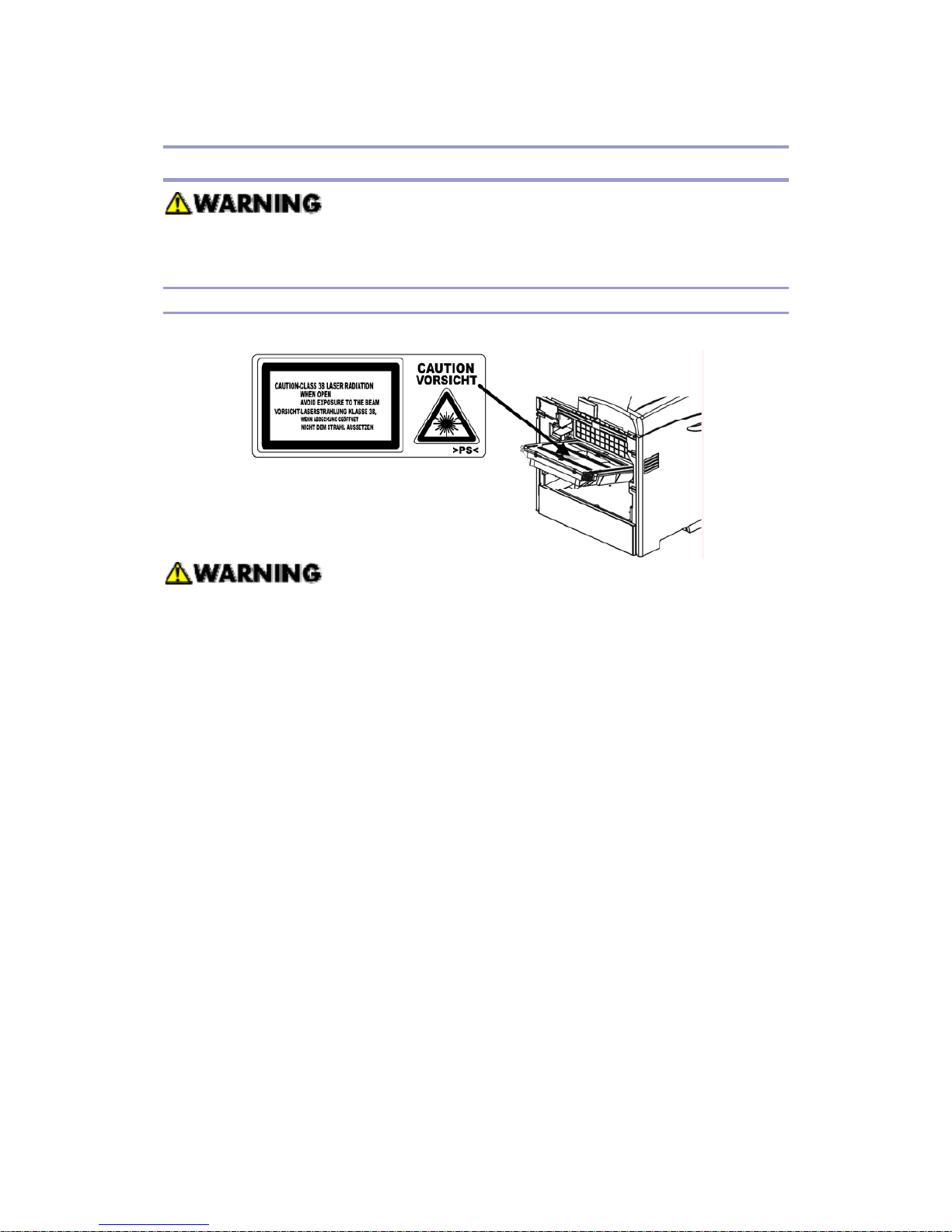
Caution Decal Locations
The caution decal is attached as shown below
Make sure to turn off the main power switch and disconnect the power plug from the
power outlet before you do any disassembly or adjustment of the laser unit. This
printer uses a class 3B laser beam with a wavelength of 655 nm and an output of 7
mW. The laser can cause serious eye injury.
Page 14
G160 Service Manual 23-Feb-06
7
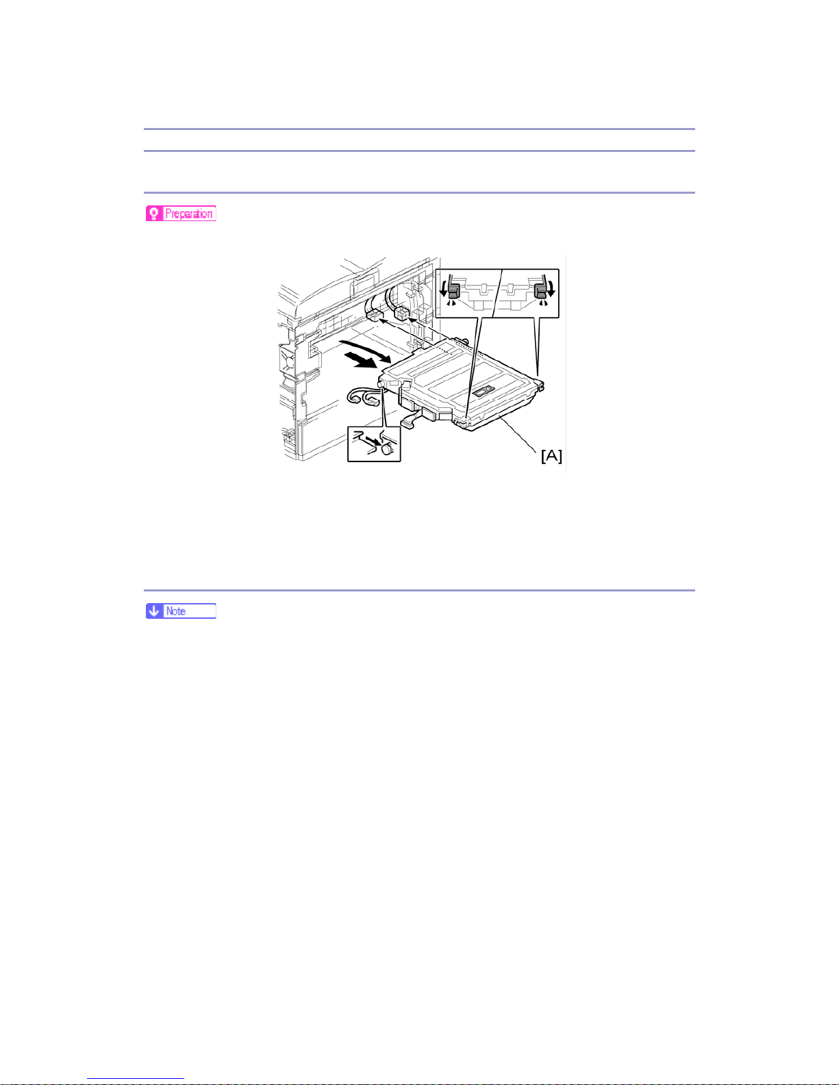
LD Unit
Replacement
Print the SMC report with SP 5990 2 before you replace the LDU.
1. Electrical board unit (see the Service Manual for G-P1 (G104/G105): ‘Electrical
Components – Electrical Board Unit’)
2. LDU [A]
Color Registration Adjustment
You must manually do the color registration adjustment after you install the new
LDU.
When the polygon mirror motor or LDB unit is defective, only replace the defective
parts. At this time, if only the motor is changed it is not necessary to do this
adjustment procedure.
1. Print the SMC report with SP 5990 2 before you replace the LDU. Find the values
for SP 2181 1, SP 2181 11, 2181 21, and 2181 31.
2. Do SP 2111 2 (Pro. Position Adj > Execute) to roughly adjust the line position after
you install the new LDU. “Result = OK” shows on the LCD if this is done correctly .
If not, do it again until you get “OK”.
3. Do SP2111 3 (Skew Adjust. > Execute) to measure the skew values for each color.
“Result = OK” shows on the LCD if this is done correctly. If not, do it again until
you get “OK”.
4. Check the skew values with SP 2181: Then write down the values. (You can also
check these if you print the SMC report again with SP 5990 2. The values will
Page 15

G160 Service Manual 23-Feb-06
8
probably be different from the values on the report that you printed in step 1.)
SP 2181 1 for black skew
SP 2181 11 for magenta
SP 2181 21 for cyan
SP 2181 31 for yellow
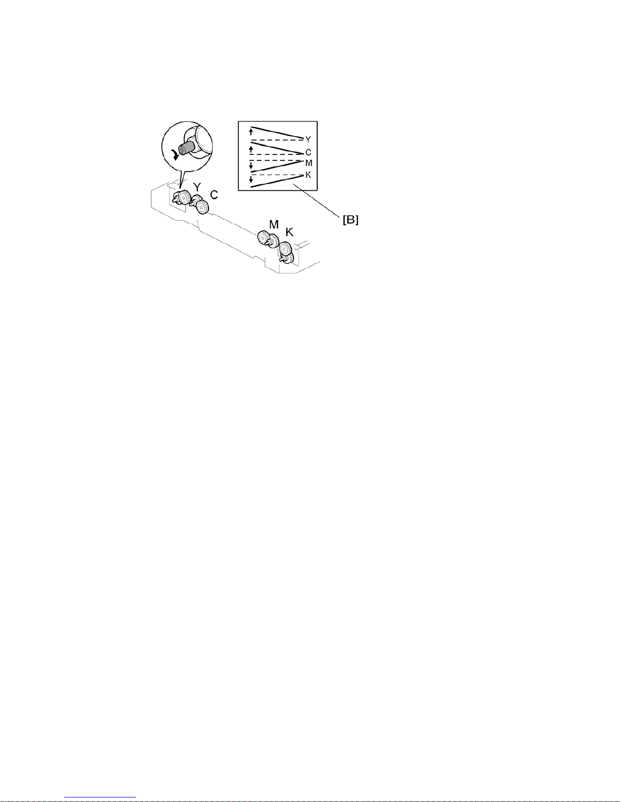
5. Open the left cover
6. Adjust the skew adjustment cam [A] for each color with a screwdriver. You must
adjust the skew values for each color until they are all the same as the value for
magenta that you found in step 1, before you replaced the LDU.
For example: If the new value for K (after step 4) is –300 and the old value for
magenta (in step 1) is –250, you must adjust the skew for K until it is –250.
Turn the cam as shown in the “Cam Rotation Direction” column below to increase
the skew value.
Turn it in the opposite direction from this to decrease the skew value.
“Adjustment value” shows the change when you turn the cam one click.
Color
Cam Rotation
Direction
Adjustment
Value
Yellow CW 14 μm
Cyan CW 10 μm
Magenta CCW 10 μm
Black CCW 10 μm
The adjustment values in the table are not exact values. These are
approximate values.
Page 16
G160 Service Manual 23-Feb-06
9
CW: Clockwise, CCW: Counter-clockwise
The diagram shows the effect on line skew [B] when you turn the cam in a
counter clockwise direction.
7. Close the left cover. Then measure the skew values again with SP 2111 3. (To do
this, repeat step 3.)
If these are close to the value for magenta that you found in step 1 (within one click in
the above table), go to the next step. If not, do SP 2111 3 again until you get a good
result.
8. Do SP 2111 1 to finely adjust the line position for each color.
Try SP 2111 2 if “Result = OK” does not show.
9. When you get “Result = OK”, this adjustment is completed.
Page 17

G160 Service Manual 23-Feb-06
10
Fusing
Make sure that the fusing unit is cool before you touch it. The fusing unit can
be very hot.
Make sure to restore the insulators, shields, etc after you service the fusing
unit.
Thermistor and Thermostat
1. Front door
2. Fusing unit (see the Service Manual for G-P1 (G105/G16): ‘Fusing Unit’)
3. Fusing unit guide plate [A] (
x 4)
4. Release the connector [B] from the fusing lower cover [C] (hook x 1).
5. Fusing lower cover [C] (
x 2)
Page 18
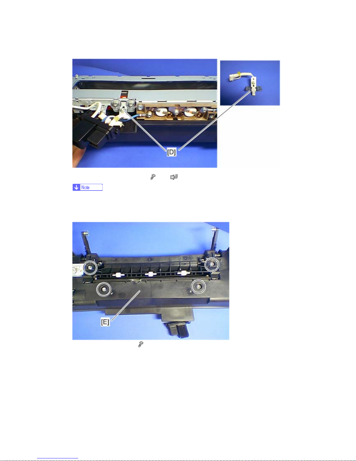
G160 Service Manual 23-Feb-06
11
6. Thermistor with bracket [D] (
x 2, x 1)
Do not remove the thermistor from the bracket when removing it. The pressure
of the thermistor plate to the fusing belt is adjusted properly in the factory. If you
remove it, some image problem may occur.
7. Fusing upper cover [E] (
x 4)
Page 19
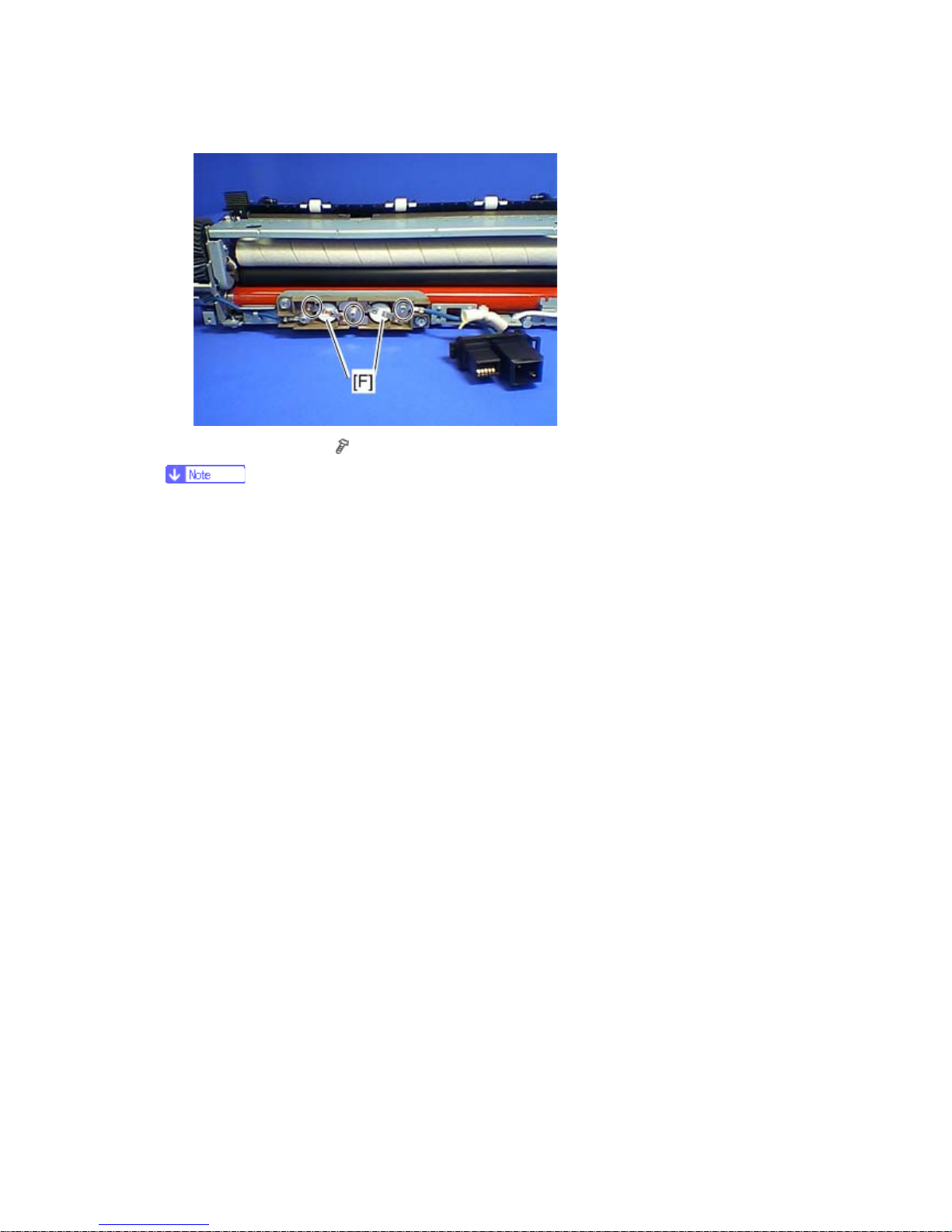
G160 Service Manual 23-Feb-06
12
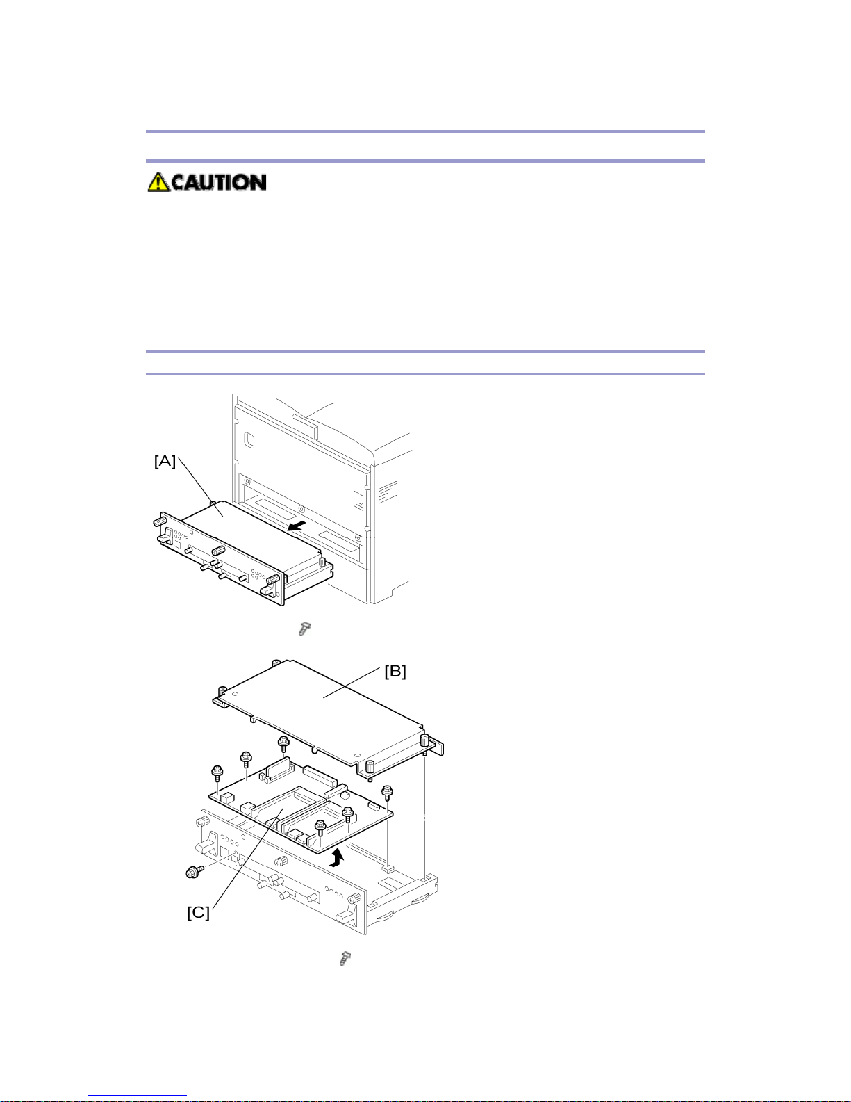
8. Thermostat [F] x 2 (
x 3)
Do not recycle a thermostat that is already opened. Safety is not guaranteed if you
do this.
Page 20
G160 Service Manual 23-Feb-06
13
Electrical Components
Before you replace the EGB (Engine Board), the controller, or the NVRAM, print
out the SMC reports (“SP Mode Data” and “Logging Data”).
After you replace the EGB (Engine Board) or the controller, remove the NVRAM
from the old board and install it on the new board. If the NVRAM on the old
board is defective, replace the NVRAM (see ‘NVRAM Replacement
Procedure’).
Controller Board
1. Controller unit [A] (
x 3)
2. Controller unit cover [B] (
x 4)
Page 21
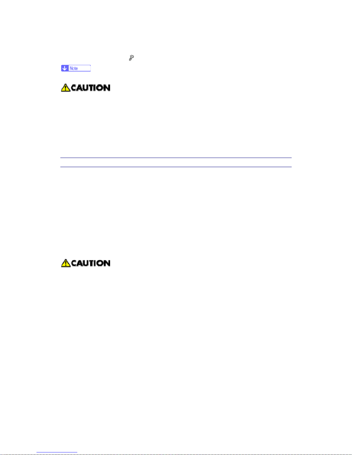
G160 Service Manual 23-Feb-06
14
3. Controller board [C] (
x 7)
Remove the NVRAM from the old board. Then install it on the new board.
Keep NVRAMs away from objects that can cause static electricity. The data in
NVRAMs can be corrupted by static electricity.
Make sure the NVRAM is correctly installed on the board. A half-disk is
engraved on one side of the NVRAM, and a guide mark is on one side of the
NVRAM slot. When you install the NVRAM, the half-disk and the guide mark
must be on the same side.
Installing the new NVRAM
When the NVRAM on the controller board is detective, you must replace the detective
NVRAM to new NVRAM.
1. Controller board (see Controller Board)
2. Remove the defective NVRAM.
3. Install the new NVRAM on the controller board.
4. Reassemble the machine.
5. Plug in and turn on the main power
6. Set the date and time with the timer setting in the UP (Maintenance < Menu ) after
installing a new controller board.
If the date and time setting is not done, the WebImage Moniter can not be available.
Page 22

G160 Service Manual 23-Feb-06
15
Troubleshooting
Process Control Results
The table below lists the process control results shown in SP 3821.
Number Result Notes
10 Success No error
21 ID sensor correction error SC 400
22 ID sensor: LED adjustment error SC 418
31 Charge bias correction error SC 300 to 307
51 High Vmin (Bk), High K2 (Color) error
SP 3145 (see the note below
the table)
52 Low K2 (Color) error
SP 3146 (see the note below
the table)
53 High K5 error
SP 3147 (see the note below
the table)
54 Low K5 error
SP 3147 (see the note below
the table)
55 High development gamma
Gamma > 5.0 (see the note
below the table)
56 Low development gamma
Gamma < 0.5 (see the note
below the table)
57 Development bias adjustment error
Vk >150V (see the note
below the table)
58 Development bias adjustment error
Vk < -150V (see the note
below the table)
90 No process control -
99 Not successful
Interrupt during the process
control (e.g. Door open)
This error code does not usually occur. If no problem is observed with image density
and/or development gamma, nothing needs to be done. If an image problem such as
low image density is observed, check the following points: Transfer belt/PCU/ID
sensor/Toner bottle
Page 23

G160 Service Manual 23-Feb-06
16
The 8 numbers on the LCD in SP 3821 indicate the process control result for each color.
There are two numbers for each color. The numbers are shown from left to right on the
display as follows: Black, Magenta, Cyan, Yellow. For example, if process control for each
color is successful: 10 (Black), 10 (Magenta), 10 (Cyan), 10 (Yellow)
Page 24
G160 Service Manual 23-Feb-06
17
Service Call Conditions
Summary
1. All SCs are logged.
2. First disconnect then reconnect the connectors before you replace the PCBs if the
problem concerns electrical circuit boards.
3. First check the mechanical load before you replace motors or sensors if the
problem concerns a motor lock.
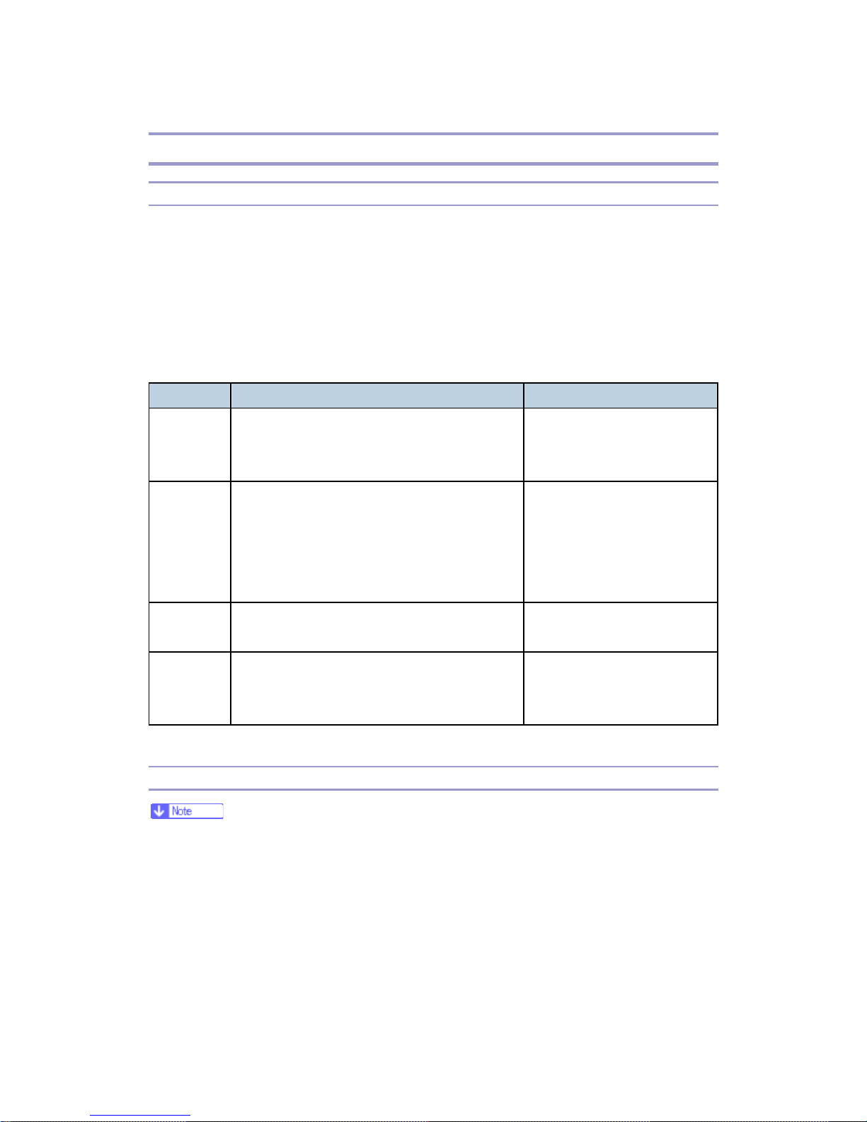
There are 4 levels of service call conditions.
Level Definition Reset Procedure
A
To prevent damage to the machine, the main
machine cannot be operated until a service
representative has reset the SC.
Do SP 5810, and then turn the
main power switch off and on.
B
SCs that disable only the features that use the
defective item. Although these SCs are not
shown to the user under normal conditions,
they are displayed on the operation panel only
when the defective feature is selected.
Turn the operation switch or
main switch off and on.
C
The SC history is updated. The machine can be
operated as usual.
The SC will not be displayed.
Only the SC history is updated.
D
Turning the main switch off then on resets SCs
displayed on the operation panel. These are
redisplayed if the error occurs again.
Turn the operation switch off
and on.
SC Code Descriptions
Remove the NVRAM from the old board and install it on the new one when you
replace the EGB or the controller board.
The SC level is indicated under SC number in the list below.
The numbers (1, etc.) in the “Possible Cause/Requirement Action” column indicate the
required actions.
Page 25

G160 Service Manual 23-Feb-06
18
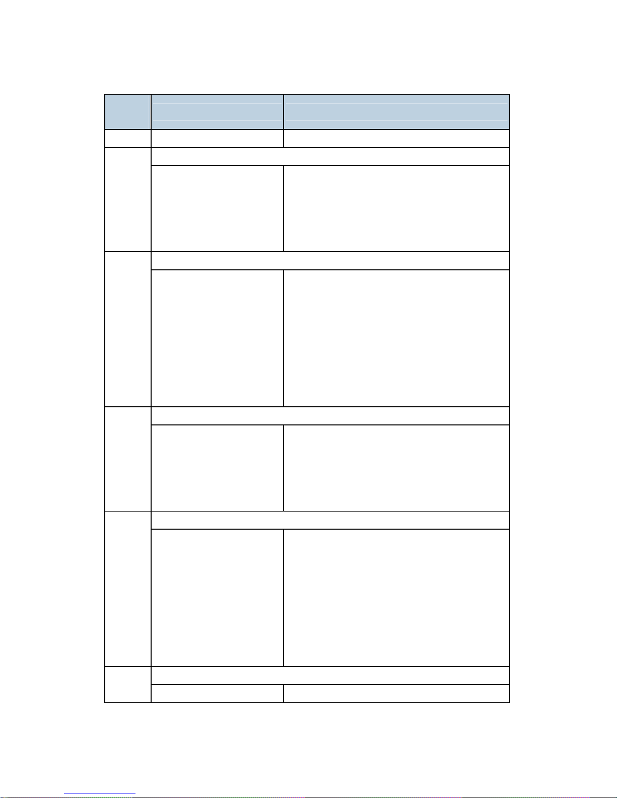
Engine SC
SC
[Level]
Symptom Possible Cause/Required Action
Incorrect serial number
195
[D]
When checking the
registered product number, it
does not match the printer’s
product number.
Registered product number does not match
the printer’s product number.
1. Ask your service key man.
Polygon motor error: Time out with the polygon motor activated
202
[D]
After the polygon motor turns
on or changes the speed,
SCRDY_N is not active
within 10 seconds.
Disconnected cable from the polygon motor
drive board or defective connection
Defective polygon motor or drive board
Polygon motor error: Time out with the polygon motor inactivated
203
[C]
After the polygon motor turns
off or changes the speed,
SCRDY_N is not inactive
within 10 seconds.
Disconnected cable from the polygon motor
drive board or defective connection
Defective polygon motor or drive board
Polygon motor error: XSCRDY signal error
204
[C]
PMRDY_N signal
consecutively detects that
the polygon motor is an
inactive state while LDB unit
scans.
Disconnected cable from the polygon motor
drive board or defective connection
Defective polygon motor or drive board
1. Check the connectors.
2. Replace the polygon motor.
3. Replace the polygon motor drive board.
Polygon motor error: XSCRDY signal not stable
205
[D]
PMRDY_N signal
consecutively detects that
the polygon motor is an
inactive state while the
polygon motor turns on or
changes the speed.
Disconnected cable from the polygon motor
drive board or defective connection
Defective polygon motor or drive board.
1. Check the connectors.
2. Replace the polygon motor.
3. Replace the polygon motor drive board.
Trailing edge laser detection error: [K]
210
[C]
The laser synchronizing
detection signal for LDB [K]
Disconnected cable from the laser
synchronizing detection unit or defective
Page 26

G160 Service Manual 23-Feb-06
19
SC
[Level]
Symptom Possible Cause/Required Action
of the trailing edge is not
detected for one second after
the LDB unit turned on when
detecting the main scan
magnification.
connection
Defective laser synchronizing detector
Defective LDB
Defective EGB
1. Check the connectors.
2. Replace the laser-synchronizing
detector.
3. Replace the LDB.
4. Replace the EGB.
Trailing edge laser detection error: [Y]
211
[C]
The laser synchronizing
detection signal for LDB [Y]
of the trailing edge is not
detected for one second after
the LDB unit turned on when
detecting the main scan
magnification.
Same as SC 210
Trailing edge laser detection error: [M]
212
[C]
The laser synchronizing
detection signal for LDB [M]
of the trailing edge is not
detected for one second after
the LDB unit turned on when
detecting the main scan
magnification.
Same as SC 210
Trailing edge laser detection error: [C]
213
[C]
The laser synchronizing
detection signal for LDB [C]
of the trailing edge is not
detected for one second after
the LDB unit turned on when
detecting the main scan
magnification.
Same as SC 210
Page 27

G160 Service Manual 23-Feb-06
20
SC
[Level]
Symptom Possible Cause/Required Action
Laser Synchronizing Detection Error: LDB of the leading edge [K]
220
[D]
The laser synchronizing
detection signal for LDB [K]
of the leading edge is not
output for two seconds after
LDB unit turns on while the
polygon motor is rotating
normally.
Disconnected cable from the laser
synchronizing detection unit or defective
connection
Defective laser synchronizing detector
Defective LDB
Defective EGB
1. Check the connectors.
2. Replace the laser-synchronizing
detector.
3. Replace the LDB.
4. Replace the EGB.
Leading edge laser detection error: [Y]
222
[D]
The laser synchronizing
detection signal for LDB [Y]
of the leading edge is not
output for two seconds after
LDB unit turns on while the
polygon motor is rotating
normally.
Same as SC 221
Leading edge laser detection error: [M]
224
[D]
The laser synchronizing
detection signal for LDB [M]
of the leading edge is not
output for two seconds after
LDB unit turns on while the
polygon motor is rotating
normally.
Same as SC 221
Leading edge laser detection error: [C]
226
[D]
The laser synchronizing
detection signal for LDB [C]
of the leading edge is not
output for two seconds after
Same as SC 221
Page 28

G160 Service Manual 23-Feb-06
21
SC
[Level]
Symptom Possible Cause/Required Action
LDB unit turns on while the
polygon motor is rotating
normally.
FGATE: On error [K]
230
[C]
The PFGATE ON signal does
not assert within 5 seconds
after processing the image in
normal job or MUSIC for [K]
starts.
Defective connection between the controller
board and EGB
Defective cable between the EGB and LDB
1. Check the connectors.
2. Replace the LDB.
3. Replace the EGB.
FGATE: Off error [K]
231
[C]
The PFGATE ON signal
still asserts within 5
seconds after processing
the image in normal job
or MUSIC for [K] ends.
The PFGATE ON signal
still asserts when the
next job starts.
Defective connection between the controller
board and EGB
Defective cable between the EGB and LDB
1. Check the connectors.
2. Replace the LDB.
3. Replace the EGB.
FGATE: On error [Y]
232
[C]
The PFGATE register of
GAVD does not assert within
5 seconds after processing
the image in normal job or
MUSIC for [Y] started.
Same as SC 230
FGATE: Off error [Y]
233
[C]
The PFGATE ON signal
still asserts within 5
seconds after processing
the image in normal job
or MUSIC for [K] ends.
The PFGATE ON signal
still asserts when the
Same as SC 231
Page 29
G160 Service Manual 23-Feb-06
22
SC
[Level]
Symptom Possible Cause/Required Action
next job starts.
FGATE: On error [M]
234
[C]
The PFGATE register of
GAVD does not assert within
5 seconds after processing
the image in normal job or
MUSIC for [M] started.
Same as SC 230
FGATE: Off error [M]
235
[C]
The PFGATE ON signal
still asserts within 5
seconds after processing
the image in normal job
or MUSIC for [M] ends.
The PFGATE ON signal
still asserts when the
next job starts.
Same as SC 231
FGATE: On error [C]
236
[C]
The PFGATE register of
GAVD does not assert within
5 seconds after processing
the image in normal job or
MUSIC for [C] started.
Same as SC 230
FGATE: Off error [C]
237
[C]
The PFGATE ON signal
still asserts within 5
seconds after processing
the image in normal job
or MUSIC for [C] ends.
The PFGATE ON signal
still asserts when the
next job starts.
Same as SC 231
LDB error [K] 240
[D]
The EGB detects LDB error a Defective LDB
Page 30

G160 Service Manual 23-Feb-06
23
SC
[Level]
Symptom Possible Cause/Required Action
few times consecutively
when LDB unit turns on after
LDB initialization.
1. Replace the LDB.
LDB error [Y]
241
[D]
The EGB detects LDB error a
few times consecutively
when LDB unit turns on after
LDB initialization.
Same as SC240
LDB error [M]
242
[D]
The EGB detects LDB error a
few times consecutively
when LDB unit turns on after
LDB initialization.
Same as SC240
LDB error [C]
243
[D]
The EGB detects LDB error a
few times consecutively
when LDB unit turns on after
LDB initialization.
Same as SC240
LDU shutter error
270
[D]
Sensor output does not
change even if 1 second
passes after the LDU shutter
motor is on.
Sensor defective or LDU shutter motor
defective
1. Replace the LDU shutter sensor or
shutter motor.
High voltage power board: Charge voltage output error [K]
300
[D]
The measured voltage is not
proper when EGB measures
the charge output for each
color.
Defective charge roller
Defective connectors
Disconnected harness
Defective high voltage power 1
1. Check the connectors.
2. Replace the PCU for black.
3. Replace the drum positioning plate.
4. Replace the high voltage power 1.
301 High voltage power board: Charge voltage output error [M]
Page 31

G160 Service Manual 23-Feb-06
24
SC
[Level]
Symptom Possible Cause/Required Action
[D]
The measured voltage is not
proper when EGB measures
the charge output for each
color.
Defective charge roller
Defective connectors
Disconnected harness
Defective high voltage power 1
1. Check the connectors.
2. Replace the PCU for magenta.
3. Replace the drum positioning plate.
4. Replace the high voltage power 1.
High voltage power board: Charge voltage output error [C]
302
[D]
The measured voltage is not
proper when EGB measures
the charge output for each
color.
Defective charge roller
Defective connectors
Disconnected harness
Defective high voltage power 1
1. Check the connectors.
2. Replace the PCU for cyan.
3. Replace the drum positioning plate.
4. Replace the high voltage power 1.
High voltage power board: Charge voltage output error [Y]
303
[D]
The measured voltage is not
proper when EGB measures
the charge output for each
color.
Defective charge roller
Defective connectors
Disconnected harness
Defective high voltage power 1
1. Check the connectors.
2. Replace the PCU for yellow.
3. Replace the drum positioning plate.
4. Replace the high voltage power 1.
Charge AC bias error [K]
304
[D]
The charge current less than
200 µA is detected.
Defective charge roller
Defective connectors
Disconnected harness
Defective high voltage power 1
1. Check the connectors.
2. Replace the PCU for black.
3. Replace the drum positioning plate.
Page 32

G160 Service Manual 23-Feb-06
25
SC
[Level]
Symptom Possible Cause/Required Action
4. Replace the high voltage power 1.
Charge AC bias error [M]
305
[D]
The charge current less than
200 µA is detected.
Defective charge roller
Defective connectors
Disconnected harness
Defective high voltage power 1
1. Check the connectors.
2. Replace the PCU for magenta.
3. Replace the drum positioning plate.
4. Replace the high voltage power 1.
Charge AC bias error [C]
306
[D]
The charge current less than
200 µA is detected.
Defective charge roller
Defective connectors
Disconnected harness
Defective high voltage power 1
1. Check the connectors.
2. Replace the PCU for cyan.
3. Replace the drum positioning plate.
4. Replace the high voltage power 1.
Charge AC bias error [Y]
307
[D]
The charge current less than
200 µA is detected.
Defective charge roller
Defective connectors
Disconnected harness
Defective high voltage power 1
1. Check the connectors.
2. Replace the PCU for yellow.
3. Replace the drum positioning plate.
4. Replace the high voltage power 1.
Color development motor error
325
[D]
LOCK signal is not
detected for more than
two seconds while the
motor START signal is
Color development motor slip due to the
increase of the load torque
1. Adjust the load torque properly by
replacing or cleaning the development
Page 33

G160 Service Manual 23-Feb-06
26
SC
[Level]
Symptom Possible Cause/Required Action
on.
LOCK signal is not
cancelled within two
seconds after the motor
is off.
unit.
2. Replace or repair the development
motor if the load torque is normal.
TD sensor: Output maximum error [K]
360
[D]
Vt is more than the maximum
value (4.5) for three times
consecutively.
Defective connector connection
Increasing toner density
1. Replace the PCU.
TD sensor: Output maximum error [M] 361
[D]
Same as SC 360
TD sensor: Output maximum error [C] 362
[D]
Same as SC 360
TD sensor: Output maximum error [Y] 363
[D]
Same as SC 360
TD sensor: Output minimum error [K]
364
[D]
Vt is less than the minimum
value (0.5) for three times
consecutively.
Defective connector connection
Decreasing toner density
1. Replace the PCU.
TD sensor Output minimum error [M] 365
[D]
Same as SC 364
TD sensor: Output minimum error [C] 366
[D]
Same as SC 364
TD sensor: Output minimum error [Y] 367
[D]
Same as SC 364
TD sensor: Initial control voltage error [K]
368
[D]
Vt is less than 1 V even
though the control power
voltage is adjusted to the
maximum.
Vt is more than 1 V even
though the control power
voltage is adjusted to the
Defective connector connection
Defective TD sensor
The toner density in the developer is different
from the initial condition.
1. Replace the PCU.
Page 34

G160 Service Manual 23-Feb-06
27
SC
[Level]
Symptom Possible Cause/Required Action
minimum.
TD sensor: Initial control voltage error [M] 369
[D]
Same as SC 368
TD sensor: Initial control voltage error [C] 370
[D]
Same as SC 368
TD sensor: Initial control voltage error [Y] 371
[D]
Same as SC 368
TD sensor: Initial adjustment error [K]
372
[D]
Vt is not (A ±0.2) when initial
setting for TD sensor is
executed.
A = SP3011-001 for [K]
Defective connector connection
Defective TD sensor
The toner density in the developer is different
from the initial condition.
1. Replace the PCU.
TD sensor: Initial adjustment error [M]
373
[D]
Vt is not (A ±0.2) when initial
setting for TD sensor is
executed.
A = SP 3011 2 for [M]
Same as 372
TD sensor: Initial adjustment error [C]: same as 372
374
[D]
Vt is not (A ±0.2) when initial
setting for TD sensor is
executed.
A = SP 3011 3 for [C]
Same as 372
TD sensor: Initial adjustment error [Y]: same as 372
375
[D]
Vt is not (A ±0.2) when initial
setting for TD sensor is
executed.
A = SP 3011 4 for [Y]
Same as 372
Drum gear position sensor error
380
[C]
When receiving the input
signal of drum gear position
sensor is not correctly done,
SC380 is logged.
Dirty or defective drum gear position sensor
1. Clean the drum gear position sensor.
2. Replace the drive unit.
Page 35

G160 Service Manual 23-Feb-06
28
SC
[Level]
Symptom Possible Cause/Required Action
Drum motor error [K]
396
[D]
The LOCK signal is not
detected for 2 seconds more
while the start signal of the
drum motor for black PCU is
output.
OPC motor slip due to the excessive load
1. Clean the PCU.
2. Check the cable from the Black OPC/
Development motor. Replace it if
necessary.
3. Replace the EGB.
4. Replace the Black OPC/Development
motor.
Drum motor error [CMY]
397
[D]
The LOCK signal is not
detected for 2 seconds more
while the start signal of the
drum motor for color PCU is
output.
Same as SC 396
ID sensor correction error
400
[D]
Regular Vsp is not (4 ±0.5V)
when ID sensor correction is
executed.
Defective ID sensors
Dirty ID sensors or transfer belt
ID sensor life is over.
1. Replace the ID sensors.
ID sensor: LED adjustment error
418
[D]
LED PWM adjustment is not
[A] for three times
consecutively.
[A] = 50 < [A] < 400
Defective ID sensors
Dirty ID sensors or transfer belt
ID sensor life is over.
1. Replace the ID sensors.
Transfer belt contact error
442
[D]
The transfer belt contact
sensor does not detect the
movement of actuator at the
sensor while the polygon
motor rotates.
Dirty transfer belt contact sensor
Defective transfer belt contact motor
Disconnected connector of transfer belt
contact sensor or motor
Disconnected cable
1. Replace the transfer belt contact sensor.
2. Replace the transfer belt contact motor.
Page 36

G160 Service Manual 23-Feb-06
29
SC
[Level]
Symptom Possible Cause/Required Action
Transfer roller contact error
452
[D]
The transfer roller contact
sensor does not detect the
movement of actuator at the
sensor while the polygon
motor rotates.
Defective transfer roller contact sensor
Defective transfer roller contact motor
Defective IOB
1. Replace the transfer roller contact
sensor.
2. Replace the transfer roller contact
motor.
3. Replace the IOB.
High Voltage Power 1: High voltage output error
490
[D]
Error signal is detected for 10
times consecutively.
One of the DC bias outputs for each PCU is
shorted or one of the transfer belt bias outputs
for [Y], [M] and [C].
Power leaking
Defective connection
Disconnected cable
Defective PCU
Defective High Voltage Power 1
1. Replace the High Voltage Power 1.
2. Reset the cables and components.
3. Replace the PCU.
High Voltage Power 2: High voltage output error
491
[D]
Error signal is detected for 10
times consecutively.
One of the separation bias output,
development bias output and transfer belt
cleaning bias output is shorted or one of the
transfer belt bias output for [K] and transfer
roller bias output is shorted.
Power leaking
Defective connection
Defective PCU
Defective High Voltage Power 2
1. Replace the High Voltage Power 2.
2. Reset the cables and components.
3. Replace the PCU.
Page 37

G160 Service Manual 23-Feb-06
30
SC
[Level]
Symptom Possible Cause/Required Action
Paper feed / Fusing motor error
531
[D]
LOCK signal is not
detected for more than
two seconds while the
motor START signal is
on.
LOCK signal is not
cancelled within two
seconds after the motor
is off.
Defective paper feed/ fusing motor
1. Replace the paper feed/ fusing motor.
Fan motor error
532
[D]
The fan motor “On” signal is
not detected for the
components below after the
drum motor for black is set to
“On”.
PSU fan
Fusing unit fan
Polygon motor fan
Drive unit fan
Exit paper fan
Defective fan motor
1. If the error occurs again, one of the fans
is defective. Remove the covers, find the
defective fan and replace it.
Thermistor error
541
[A]
The thermistor output is less
than 0 °C for six seconds.
Disconnected thermistor
Defective connector connection
Print ready temperature error
542
[A]
The heating roller
temperature increase
that is less than 67
degrees for 9 seconds is
detected five times
consecutively.
The fusing temperature
does not reach the print
Defective thermistor
Thermistor coming off
Incorrect power supply input at the main power
socket
Defective fusing lamp
Page 38

G160 Service Manual 23-Feb-06
31
SC
[Level]
Symptom Possible Cause/Required Action
ready temperature within
15 seconds after the
fusing lamp was
controlled.
High temperature detection: Software
543
[A]
The thermistor detects 230°C
for 0.2 seconds.
Defective thermistor
Defective I/O board
Defective EGB
High temperature detection: Hard
544
[A]
The thermistor detects
250°C.
Defective thermistor
Defective I/O board
Defective EGB
Defective fusing unit, PSU, or EGB
1. Replace the fusing unit.
2. Replace the PSU.
Heating lamp error
545
[A]
The fusing lamp is
full-powered for 8 seconds
after the heating roller
reaches the print ready
temperature.
Deformed thermistor
Thermistor coming off
Defective fusing lamp
Zero cross error
547
[D]
The zero cross signal is
detected three times
even though the heater
relay is off when turning
on the main power.
The zero cross signal is
not detected for three
seconds even though the
heater relay is on after
turning on the main
power or closing the front
Defective fusing lamp relay
Defective fusing lamp relay circuit
Unstable power supply
1. Check the power supply source.
2. Replace the PSU.
Page 39

G160 Service Manual 23-Feb-06
32
SC
[Level]
Symptom Possible Cause/Required Action
door.
The detection error
occurs twice or more in
the ten zero cross signal
detections. This error is
defined when the
detected zero cross
signal is less than 17 for
200 ms.
Zero cross frequency error
557
[C]
The detection error occurs
ten times in a row in ten zero
cross signal detections. This
error is defined when the
detected zero cross signal is
more than 28 for 200 ms.
This SC is only logged. In this
case, the power frequency is
defined as 60 Hz.
Noise (high frequency)
1. Check the power supply source.
Continuous paper jam at Fusing unit
559
[A]
The paper jam occurs three
times consecutively at the
fusing unit only when the SP
1159 1 is set to "1 (ON)". If
not, this SP does not occur.
The jam counter is cleared
when a sheet of paper is fed
normally.
Defective fusing entrance sensor
Defective EGB
1. Replace the fusing entrance sensor.
2. Replace the EGB.
Controller board command error
687
[D]
A command from the
controller board is not
received.
Loose connection
Defective controller board
Defective EGB
1. Check the connection of the controller
board.
Page 40

G160 Service Manual 23-Feb-06
33
SC
[Level]
Symptom Possible Cause/Required Action
2. Replace the controller board.
3. Replace the EGB.
EGB data error
690
[D]
The data transfer in the EGB
is interrupted by some
incident (e.g. cover open
etc.) during the data transfer.
Defective EGB
1. Replace the EGB.
Controller Error
The following table shows the controller error codes. These codes show at these times if an
error occurs:
Power-on
After the power-on self diagnostic test
Always try turning the main switch off and on and check if the problem persists.
SC
[Level]
Symptom Possible Cause/Required Action
636 SD Card Error
Expanded authentication module error
-001
[B]
There is no expanded
authentication module in the
machine.
The SD card or the file of the
expanded authentication
module is broken.
There is no DESS module in
the machine.
No expanded authentication module
Defective SD card
No DESS module
1. Install the expanded authentication
module.
2. Install the SD card.
3. Install the DESS module.
Version error
-002
[B]
The version of the expanded
authentication module is not
correct.
Incorrect module version
1. Install the correct file of the expanded
authentication module.
Page 41

G160 Service Manual 23-Feb-06
34
SC
[Level]
Symptom Possible Cause/Required Action
Engine start-up error
670
[D]
A command from the
controller board is not
received.
Defective engine board.
1. Replace the engine board.
Watchdog error
818
[B]
While the system program is
running, no other programs
can run (due to a bus hold or
endless loop).
Defective system program
Defective controller board
1. Reinstall the system program.
2. Replace the controller board.
819 Kernel stop
Process error
[0696e]
[B]
System completely down
Defective RAM DIMM
Defective controller
Software error
1. Check and/or replace the RAM DIMM.
2. Replace the controller.
VM full error
[0766d]
[B]
Unexpected system memory
size
Defective RAM DIMM
Defective controller
Software error
1. Check and/or replace the RAM DIMM.
2. Replace the controller.
Cache error
[4361]
[B]
Cache error in the CPU
Defective CPU
1. Replace the controller board.
The others
[----]
[B]
Error in OS
Defective memory
Defective flash memory
Defective CPU
1. Replace the controller board.
820 Self-Diagnostic Error: CPU
[0001-0015] [000A-000D]: Detailed error code
[B]
During the boot monitor Defective CPU device
Page 42

G160 Service Manual 23-Feb-06
35
SC
[Level]
Symptom Possible Cause/Required Action
program and self-diagnostic,
any exception or cut-in are
not supposed to happen. If
these happen, it is defined as
SC.
Defective boot monitor program or
self-diagnostic program
1. Replace the controller board.
2. Reinstall the system firmware.
[00FF]: Detailed error code
[B]
Cache access error in the
CPU
Defective CPU
Defective local bus
1. Turn the main power switch off and on.
2. Reinstall the system program.
3. Replace the controller board.
[0601, 0602, 0605, 0606, 0607, 0609]: Detailed error code
[B]
Exceptional command does
not operate even though it is
executed on purpose.
Defective CPU devices
1. Replace the controller board.
[B] [060A-060E]: Detailed error code
Cut-in command does not
operate when it is executed.
Defective CPU devices
Defective ASIC devices
1. Replace the controller board.
[0610]: Detailed error code
[B]
Timer cut-in does not operate
even though it is set.
Defective CPU devices
1. Replace the controller board.
[0612]: Detailed error code
[B]
Cut-in in ASIC occurs.
Defective ASIC
Defective devices in which ASIC detects
cut-in.
1. Replace the controller board.
[06FF]: Detailed error code
[B]
The pipeline clock frequency
rate is different from the
prescribed value.
Defective CPU devices
Mode bit data error, which is used for
initializing CPU.
1. Replace the controller board.
[B] [0702]: Detailed error code
Page 43

G160 Service Manual 23-Feb-06
36
SC
[Level]
Symptom Possible Cause/Required Action
The result when the program
is executed in the command
cache is different from
desirable value.
Insufficient CPU cache
Insufficient memory process speed
1. Replace the controller board.
2. Replace the RAM DIMM.
[0709, 070A]: Detailed error code
[B]
Even you write the data in the
only cache of memory, the
data is actually written in
another area (not cache) of
memory.
Defective CPU devices
Incorrect SPD
Boot mode setting error
1. Replace the controller board.
2. Replace the RAM DIMM.
[0801, 0804, 0807, 0808, 0809, 80A]: Detailed error code
[B]
An error occurs when
checking the TLB.
Defective CPU devices
1. Replace the controller board.
[4002-4005]: Detailed error code
[B]
The calculation error in the
CPU occurs.
Defective CPU
1. Replace the CPU.
821 Self-Diagnostic Error: ASIC
ASIC error
[0B00]
[B]
The write-&-verify check error
has occurred in the ASIC.
Defective controller board
1. Replace the controller.
ASIC not detected
[0B06]
[B]
The ASIC of the I/O is not
detected.
ASIC (controller board defective)
Poor connection between North Bridge and
PCI I/F.
1. Replace controller board.
SHM register check error
[0B10]
[B]
Failed to initialize or could not
read connection bus. Data in
SHM register incorrect.
Defective bus connection
Defective SHM
1. Replace controller board
Timer error between ASIC and CPU
[0D05]
[B]
The CPU checks if the ASIC
timer works properly
compared with the CPU timer.
System firmware problem
Defective RAM-DIMM
Defective controller
Page 44

G160 Service Manual 23-Feb-06
37
SC
[Level]
Symptom Possible Cause/Required Action
If the ASIC timer does not
function in the specified
range, this SC code is
displayed.
Reinstall the controller system firmware.
1. Replace the RAM-DIMM.
2. Replace the controller board.
822 Self-Diagnostic Error: HDD
Timeout error/ [3004]: Command error
[3003]
[B]
When the main switch is
turned on or starting the
self-diagnostic, the HDD
stays busy for the specified
time or more.
Loose connection
Defective HDD
Defective controller
1. Check that the HDD is correctly
connected to the controller.
2. Replace the HDD.
3. Replace the controller.
823 Self-diagnostic Error: NIB
MAC address check sum error
[6101]
[B]
The result of the MAC
address check sum does not
match the check sum stored
in ROM.
Defective controller
1. Replace the controller.
PHY IC error
[6104]
[B]
The PHY IC on the controller
cannot be correctly
recognized.
Same as SC823-[6101]
PHY IC loop-back error
[6105]
[B]
An error occurred during the
loop-back test for the PHY IC
on the controller.
Same as SC823-[6101]
Self-diagnostic Error: NVRAM
824
[B]
The controller cannot
recognize the standard
NVRAM installed or detects
that the NVRAM is defective.
NVRAM damaged or abnormal
Backup battery has discharged
NVRAM socket damaged
1. Replace the NVRAM.
826 Self-diagnostic Error: RTC/Optional NVRAM
Page 45

G160 Service Manual 23-Feb-06
38
SC
[Level]
Symptom Possible Cause/Required Action
Clock error
[1501]
[B]
An RTC device is
recognized, and the
difference between the
RTC device and the CPU
exceeds the defined limit.
No RTC device is
recognized.
RTC defective
NVRAM without RTC installed
Backup battery discharged
1. Replace the NVRAM with another
NVRAM with an RTC device.
RTC not detected
[15FF]
[B]
The RTC device is not
detected.
NVRAM without RTC installed
Backup battery discharged
1. Replace the NVRAM with another
NVRAM with an RTC device.
827 Self-diagnostic Error: RAM
Verification error
[0201]
[B]
Error is detected during a
write/verify check for the
standard RAM (SDRAM
DIMM).
Loose connection
Defective SDRAM DIMM
Defective controller
1. Replace the SDRAM DIMM.
2. Replace the controller.
Resident memory error
[0202]
[B]
The SPD values in all RAM
DIMM are incorrect or
unreadable.
Defective RAM DIMM
Defective SPD ROM on RAM DIMM
Defective 12C bus
1. Replace the RAM DIMM.
828 Self-diagnostic Error: ROM
Boost lap code error
[0101]
[B]
The boot monitor and OS
program stored in the ROM
DIMM is checked. If the check
sum of the program is
incorrect, this SC code is
displayed.
Defective ROM DIMM
Defective controller
1. Replace the ROM DIMM.
2. Replace the controller.
Page 46

G160 Service Manual 23-Feb-06
39
SC
[Level]
Symptom Possible Cause/Required Action
ROMFS error
[0104]
[B]
All areas of the ROM DIMM
are checked. If the check sum
of all programs stored in the
ROM DIMM is incorrect, this
SC code is displayed.
Defective ROM DIMM
1. Replace the ROM DIMM.
829 Self-diagnostic Error: Optional RAM
Verification error (Slot 1)
[0401]
[B]
The data stored in the RAM in
Slot 1 does not match the
data when reading.
Not specified RAM DIMM installed
Defective RAM DIMM
1. Replace the RAM DIMM.
2. Replace the controller board.
Composition error (Slot 1)
[0402]
The result of checking the
composition data of the RAM
in Slot 1 on the controller is
incorrect.
Not specified RAM DIMM installed
Defective RAM DIMM
1. Replace the RAM DIMM.
2. Replace the controller board.
IEEE1394 interface error
851
[B]
The 1394 interface is
unusable.
Defective IEEE1394
Defective controller.
1. Replace the IEEE1394 interface board.
2. Replace the controller.
Wireless LAN or Bluetooth card not detected at starting communication
853
[B]
The wireless LAN or
Bluetooth card is not detected
before communication is
established, though the
wireless LAN or Bluetooth
board is detected.
Loose connection
1. Check the connection.
2. Insert the wireless LAN or Bluetooth
card to its board.
Wireless LAN or Bluetooth card not detected during operation
854
[B]
The wireless LAN or
Bluetooth card is not detected
after communication is
Loose connection
1. Check the connection.
2. Insert the wireless LAN or Bluetooth
Page 47

G160 Service Manual 23-Feb-06
40
SC
[Level]
Symptom Possible Cause/Required Action
established, though the
wireless LAN or Bluetooth
board is detected.
card to its board.
Wireless LAN or Bluetooth card error
855
[B]
An error is detected in the
wireless LAN or Bluetooth
card.
Loose connection
Defective wireless LAN or Bluetooth card
1. Check the connection.
2. Replace the wireless LAN or Bluetooth
card.
Wireless LAN or Bluetooth board error
856
[B]
An error is detected in the
wireless LAN or Bluetooth
board.
Defective wireless LAN or Bluetooth board
Loose connection
1. Check the connection.
2. Replace the wireless LAN or Bluetooth
board.
USB interface error
857
[B]
The USB interface cannot be
used due to a driver error.
Defective USB driver
Loose connection
1. Check the connection.
2. Replace the controller.
HDD: Initialization error
860
[B]
The controller detects that the
hard disk fails.
HDD not initialized
Defective HDD
1. Reformat the HDD (SP5832).
2. Replace the HDD.
HDD: Reboot error
861
[D]
The HDD does not become
ready within 30 seconds after
the power is supplied to the
HDD.
Loose connection
Defective cables
Defective HDD
Defective controller
1. Check the connection between the HDD
and controller.
2. Check and replace the cables.
Page 48

G160 Service Manual 23-Feb-06
41
SC
[Level]
Symptom Possible Cause/Required Action
3. Replace the HDD.
4. Replace the controller.
HDD: Read error
863
[D]
The data stored in the HDD
cannot be read correctly.
Defective HDD
Defective controller
1. Replace the HDD.
2. Replace the controller.
HDD: CRC error
864
[D]
While reading data from the
HDD or storing data in the
HDD, data transmission fails.
Defective HDD
1. Replace the HDD.
HDD: Access error
865
[D]
An error other than SC863
and SC864 is detected while
operating the HDD.
Defective HDD
1. Replace the HDD.
SD card authentication error
866
[B]
A correct license is not found
in the SD card.
SD-card data is corrupted.
1. Store correct data in the SD card.
SD card error
867
[D]
The SD card for an
application is ejected from the
slot.
The SD card for an application is ejected from
the slot.
1. Install the SD card.
SD card access error [File system error, Device error]
868
[D]
SD card error occurs when
SD card is activated.
Defective SD card
Defective SD card controller
1. For a file system error, format the SD
card on your PC.
2. For a device error, turn the mains switch
off and on.
3. Replace the SD card.
4. Replace the controller.
Address data error 870
[B]
An error is detected in the Defective software program
Page 49

G160 Service Manual 23-Feb-06
42
SC
[Level]
Symptom Possible Cause/Required Action
data copied to the address
book over a network.
Defective HDD
Incorrect path to the sever
1. Initialize the address book data
(SP5846-50).
2. Initialize the user information (format the
hard disk with SP5832).
3. Replace the HDD.
HDD mail data error
872
[B]
An error is detected in the
mail receiving data area of
the HDD at machine
initialization.
Defective HDD
Power failure during an access to the HDD
1. Initialize the HDD (SP5-832-001).
2. Replace the HDD.
HDD mail transfer error
873
[B]
An error is detected in the
mail transmitting data area of
the HDD at machine
initialization.
Defective HDD
Power failure during an access to the HDD
1. Initialize the HDD (SP5-832-001).
2. Replace the HDD.
Delete All error 1: HDD
874
[D]
An error is detected while the
all data of the HDD or
NVRAM are formatted
physically by the Data
Overwrite Security Unit
(B735).
Not installed Data Overwrite Security Unit (SD
card)
Defective HDD
1. Install the Data Overwrite Security Unit
(B735).
2. Replace the HDD.
Delete All error 2: Data area
875
[D]
An error is detected while the
all data of the HDD or
NVRAM are formatted
logically by the Data
Overwrite Security Unit
(B735).
The logical format for HDD fails.
1. Turn the main switch off/on and try the
operation again.
876 Log Data Error
001 Log Data Error 1
Page 50

G160 Service Manual 23-Feb-06
43
SC
[Level]
Symptom Possible Cause/Required Action
[D] An error was detected in the handling of the log data at power on or during
machine operation. This can be caused by switching the machine off while it is
operating.
1. Initialize the HDD with SP5832-004.
Log Data Error 2
002
[D]
The DESS module is not installed when the DESS module is set to ON.
1. Replace the DESS module.
2. Turn off the DESS module function.
Log Data Error 3
003
[D]
Invalid encryption key log due to defective NVRAM data
1. Initialize the HDD with SP5832-004.
2. Disable the log encryption setting.
Log Data Error 4
004
[D]
Unusual encryption function log due to the defective NVRAM data
1. Initialize the HDD with SP5832-004.
Log Data Error 5
005
[D]
NVRAM or HDD, which is used in other machine, is installed.
1. Reinstall the previous NVRAM or HDD.
2. Initialize the HDD with SP5832-004.
Log Data Error 99
099
[D]
Other than above causes
1. Ask your supervisor.
HDD Data Overwrite Security SD card error
877
[B]
The all delete cannot be
executed even though the
Data Overwrite Security Unit
(B735) is installed and
activated.
Defective SD card (B735)
Not installed SD card (B735)
1. Replace the NVRAM and then install the
new SD card (B735).
2. Check and reinstall the SD card (B735).
Electric counter error
900
[D]
Abnormal data is stored in the
counters.
Defective NVRAM
Defective controller
1. Turn the main switch off and on.
2. Check the connection between the
Page 51

G160 Service Manual 23-Feb-06
44
SC
[Level]
Symptom Possible Cause/Required Action
NVRAM and controller.
3. Replace the NVRAM.
4. Replace the controller.
Printer function error
920
[B]
The error that causes the
malfunction in the software
application is detected.
Turn the main switch off/on, or install Printer
Application firmware
Unexpected hardware structure (insufficient
memory or hard disk space.)
Printer font error
921
[B]
No font is detected in the
machines that have the font in
the SD card when the printer
application is run.
Install the System, Printer Application, NIB,
and Web System firmware.
Software performance error 1
990
[D]
The software makes an
unexpected operation.
Defective software
Defective controller
Software error
1. Reinstall the controller and/or engine
main firmware.
2. See the Note at the end of the SC table.
Software performance error 2
991
[C]
Unexpected software error
detected, which does not
affect operation of the
machine
The machine does not stop and the SC code is not
displayed. The machine automatically recovers.
However, the SC code is logged in the engine
summary sheet (SMC).
SC not defined
992
[D]
SC that is not controlled in the
system occurs.
Defective system software
Application start error
998
[D]
No applications start within 60
seconds after the power is
turned on.
Loose connection of RAM, DIMM and SD card
in slot 1
Defective controller
Software problem
Page 52

G160 Service Manual 23-Feb-06
45
SC
[Level]
Symptom Possible Cause/Required Action
1. Check if the RAM, DIMM and SD card in
slot 1 are properly connected.
2. Reinstall the controller system firmware.
3. Replace the controller.
If a problem always occurs in a specific condition (for example. printer driver setting,
image file), the problem may be caused by a software error. In this case, the
following data and information needs to be sent back to your product specialist.
Symptom / Possible Causes / Action taken
Summary sheet (SP mode “1 Service/Printer SP”, SP 1004 [Print Summary])
SMC - All (SP 5990 2)
SMC - Logging (SP 5990 4)
Printer driver settings used when the problem occurs
All data displayed on the screen (SC code, error code, and program address
where the problem is logged.)
Image file which causes the problem, if possible
Page 53

G160 Service Manual 23-Feb-06
46
Troubleshooting Guide
Remove the NVRAM from the original engine control board and install it on the new
one when you replace the engine control board.
Blank Print
Symptom Possible cause Necessary actions
Defective LDU Replace the LDU.
Defective PCU Replace the PCU.
Defective transfer belt unit Replace the transfer belt unit.
Incorrect action of transfer
roller
Check the guide and the
transfer roller.
Defective high voltage supply
board
Replace high voltage supply
board 1 or 2.
No image is printed.
Defective engine board (EGB)
Replace the engine board
(EGB).
All-black Print
Symptom Possible cause Necessary actions
Incorrectly installed PCU Install the PCU correctly.
Defective PCU Replace the PCU.
Defective high voltage supply
board
Replace high voltage supply
board 1 or 2.
Defective LDU Replace the LDU.
Defective engine board (EGB)
Replace the engine board
(EGB).
All the paper is black.
Defective main board Replace the main board.
Missing CMY Color
Symptom Possible cause Necessary actions
Defective PCU Replace the PCU. C, M, or Y is missing.
Loose connection between Replace the drum positioning
Page 54

G160 Service Manual 23-Feb-06
47
Symptom Possible cause Necessary actions
printer cartridge and engine
board (EGB)
cover. (See ‘Replacement and
Adjustment – Electrical
Components – Electrical Board
Unit’.)
Transfer belt not contacting
PCU
Check the belt tension unit.
Defective the color OPC
motor
Replace the color OPC motor.
Defective engine board (EGB)
Replace the engine board
(EGB).
Light Print
Symptom Possible cause Necessary actions
Loose connection between
transfer roller and high voltage
supply unit
Check the connection
between the transfer roller and
the high voltage supply unit.
Dust in the laser beam path Clean the laser beam path.
Transfer belt not contacting
PCU
Check the transfer unit.
Defective PCU Replace the PCU.
Defective transfer roller Repair the transfer roller.
Defective fusing unit Replace the fusing unit.
Printed images are too weak.
Defective engine board (EGB)
Replace the engine board
(EGB).
Repeated Spots or Lines on Prints
The same spots or lines appear at regular intervals.
Interval Possible cause Necessary actions
At intervals of 35.0 mm (1.38
inches)
Defective charge roller Replace the PCU.
At intervals of 35.8 mm (1.41
inches)
Defective OPC cleaning brush
roller
Replace the PCU.
Page 55

G160 Service Manual 23-Feb-06
48
Interval Possible cause Necessary actions
At intervals of 40.5 mm (1.59
inches)
Defective belt entrance roller
Replace the transfer belt
unit.
At intervals of 41.1 mm (1.62
inches)
Defective belt transfer roller
Replace the transfer belt
unit.
At intervals of 47.1 mm (1.86
inches)
Defective toner mixing auger Replace the PCU.
At intervals of 56.5 mm (2.23
inches)
Defective development roller Replace the PCU
At intervals of 72.8 mm (2.87
inches)
Defective belt tension roller
Replace the transfer belt
unit.
At intervals of 82.2 mm (3.24
inches)
Defective transfer belt drive
roller
Replace the transfer belt
unit.
At intervals of 82.5 mm (3.25
inches)
Defective transfer roller Replace the transfer roller.
At intervals of 94.2 mm (3.71
inches)
Defective OPC drum or
pressure roller
Replace the PCU or the
fusing unit
At intervals of 141.4 mm (5.57
inches)
Defective fusing belt Replace the fusing unit.
Dark Vertical Line on Prints
Symptom Possible cause Necessary actions
.
A dark line appears. The line is
parallel to the paper feed
direction of one CMY color.
Defective PCU Replace the PCU.
Dust in the laser beam path Clean the laser beam path.
Defective transfer belt unit Replace the transfer belt unit.
A dark line appears. The line is
parallel to the paper feed
direction of any color (not C, M,
or Y).
Defective fusing unit Replace the fusing unit.
White Horizontal Lines or Bands
Symptom Possible cause Necessary actions
Page 56

G160 Service Manual 23-Feb-06
49
Symptom Possible cause Necessary actions
Defective PCU Replace the PCU.
Defective transfer belt unit Replace the transfer belt unit.
White lines or bands appear in
images of all toner colors.
Defective transfer roller Replace the transfer roller.
Missing Parts of Images
Symptom Possible cause Necessary actions
Defective PCU Replace the PCU.
Defective transfer belt unit Replace the transfer belt unit.
Defective transfer roller Replace the transfer roller.
Some parts of images are
missing.
Defective fusing unit Replace the fusing unit.
Dirty Background
Symptom Possible cause Necessary actions
Backgrounds of one CMYK
color are too dense.
Defective PCU Replace the PCU.
Backgrounds of more than
one CMYK are too
dense.color
Defective high voltage supply
board
Replace the high voltage
supply board (1 or 2).
Partial CMY Color Dots
Symptom Possible cause Necessary actions
Defective PCU Replace the PCU.
Defective transfer belt unit Replace the transfer belt unit.
Unexpected dots of the same
color appear at irregular
intervals.
Defective fusing unit Replace the fusing unit.
Dark Irregular Streaks on Prints
Symptom Possible cause Necessary actions
Unexpected streaks appear at
irregular intervals.
Defective transfer belt Replace the transfer belt unit.
Page 57

G160 Service Manual 23-Feb-06
50
CMY Color Irregular Streaks
Symptom Possible cause Necessary actions
Defective PCU Replace the PCU. Unexpected streaks of the
same color appear at irregular
intervals.
Defective transfer belt unit Replace the transfer belt unit.
Ghosting
Symptom Possible cause Necessary actions
Defective PCU Replace the PCU. The same or similar image
appears two or more times.
They get weaker and weaker.
Defective transfer unit Replace the transfer unit.
Unfused or Partially Fused Prints
Symptom Possible cause Necessary actions
Non-standard paper in use Use recommended paper.
Incorrect media type mode
Select an appropriate media
mode.
Some parts of images are not
fused very well.
Defective fusing unit Replace the fusing unit.
Page 58

G160 Service Manual 23-Feb-06
51
Image Skew
Symptom Possible cause Necessary actions
Incorrect installation of paper Install the paper correctly.
Incorrect paper guide position
Adjust the paper guide
correctly.
Defective registration roller Repair the paper feed unit.
Incorrect action of transfer
roller
Check the transfer roller.
Defective engine board (EGB)
Replace the engine board
(EGB).
Unclean separation pad Clean the separation pad.
Images are skewed
Defective spring
Replace the spring for the
friction pad.
Background Stain
Symptom Possible cause Necessary actions
Unclean transfer roller Clean the transfer roller.
Unclean paper path Clean the paper path.
Unclean registration roller Clean the registration roller.
Unclean fusing unit exit Clean the fusing unit exit.
The reverse side of the paper
is not clean.
Defective fusing unit Replace the fusing unit.
No Printing on Paper Edge
Symptom Possible cause Necessary actions
Defective PCU Replace the PCU.
Defective toner cartridge Replace the toner cartridge.
Defective transfer belt unit Replace the transfer belt unit.
Images are not printed in the
areas around the paper
edges.
Transfer belt not contacting
PCU
Check the transfer unit.
Page 59

G160 Service Manual 23-Feb-06
52
Image not centered when it should be
Symptom Possible cause Necessary actions
Incorrect installation of paper Install the paper correctly.
Incorrect paper guide position
Adjust the paper guide
correctly.
Incorrect margin setting Adjust the margin setting.
Images do not come to the
center.
Defective engine control
board
Replace the engine control
board.
Page 60

G160 Service Manual 23-Feb-06
53
Electrical Component Defects
Sensors
No.
Sensor Name/
Sensor Board Name
Active
CN No./
Pin No.
Condition Symptom
Open
1
Color Drum Gear
Position Sensor
H CN222/2
Shorted
SC380
Open
2
Black Drum Gear
Position Sensor
H CN222/5
Shorted
SC380
Open
Toner end cannot be
detected.
3
Toner End Sensor (K)
Toner End Sensor (M)
Toner End Sensor (C)
Toner End Sensor (Y)
L
CN222/8
CN230/13
CN230/26
CN230/29
Shorted
Toner end is detected
even if there is enough
toner.
Open
4
Transfer Belt Contact
Sensor
H CN222/11
Shorted
SC442
Open
5
Transfer Roller
Contact Sensor
L CN222/14
Shorted
SC452
Open
6
TD Sensor (K)
TD Sensor (M)
TD Sensor (C)
TD Sensor (Y)
A
CN222/20
CN225/4
CN230/4
CN230/20
Shorted
SC368 (K)
SC369 (M)
SC370 (C)
SC371 (Y)
Open
8 Transfer Belt Rotation L CN222/27
Shorted
Automatic line position
adjustment error:
Transfer belt unit
speed cannot be
detected, causing
image skew.
Open
“Close Front/Left
Cover” is displayed.
10 Front Door Sensor H CN206/1
Shorted
Front cover open
cannot be detected.
Open
Waste Toner near full
is indicated.
11
Waste Toner Overflow
Sensor
H CN230/10
Shorted Waste toner full cannot
Page 61

G160 Service Manual 23-Feb-06
54
No.
Sensor Name/
Sensor Board Name
Active
CN No./
Pin No.
Condition Symptom
be detected even if the
waste toner bottle is
full.
Open
“Close Front/Left
Cover” is displayed.
12 Left Cover Sensor H C230/15
Shorted
Left cover open cannot
be detected.
Open
13
Temperature/Humidity
Sensor
A A CN231/1
CN231/3
Shorted
Printed image is
wrong, such as rough
image, dirty
background or weak
image.
Open
14 Paper Size Sensor L
CN214/17
CN214/15
CN214/14
CN214/13
Shorted
Paper size error
Open
Paper jam is not
detected even if there
is paper
15
Fusing Entrance
Sensor
L CN213/6
Shorted
Paper jam is detected
even if there is no
paper.
Open
Paper jam is not
detected even if there
is paper
16 Duplex Jam Sensor 1 L CN213/1
Shorted
Paper jam is detected
even if the there is no
paper.
Open
Paper jam is not
detected even if there
is paper
17 Duplex Jam Sensor 2 L CN213/3
Short
Paper jam is detected
even if the there is no
Page 62

G160 Service Manual 23-Feb-06
55
No.
Sensor Name/
Sensor Board Name
Active
CN No./
Pin No.
Condition Symptom
paper.
Open
Paper is not detected
on the by-pass tray
18
By-pass Paper
Detection Sensor
L CN211/22
Shorted
Paper is detected even
if there is no paper on
the by-pass tray.
Open
19
By-pass Paper Size
Sensor
L
CN211/17
CN211/16
CN211/20
CN211/19
Shorted
Paper size error
Open
20 Inverter Sensor L CN211/2
Shorted
Paper jam Z
Open
21 Fusing Exit Sensor L CN210/13
Shorted
Paper jam A
Open
The paper overflow
message is not
displayed even when a
paper overflow
condition exists,
causing paper jam.
22
Paper Overflow
Sensor
L CN210/10
Shorted
The paper overflow
message is displayed.
Open
23 Paper Exit Sensor L CN210/7
Shorted
Paper Jam A
Open
24 ID Sensors A CN209
Shorted
SC400/418
Open
25 Fusing Thermistor A CN209/1
Shorted
SC541
Open
26 Fusing Set Sensor
L L CN209/3
CN209/4
Shorted
“Reset Fusing Unit
correctly” is displayed.
Open
“Close Top Cover” is
displayed.
27 Top Cover Sensor H CN208/2
Shorted Top cover open cannot
Page 63

G160 Service Manual 23-Feb-06
56
No.
Sensor Name/
Sensor Board Name
Active
CN No./
Pin No.
Condition Symptom
be detected.
Open
28 LDU Shutter Sensor H CN207/17
Shorted
SC270
Open
29 Registration Sensor L CN207/14
Shorted
Paper Jam A
Open
Always, small paper is
detected, causing slow
printing.
30 Paper Width Sensor H CN207/11
Shorted
Small paper size is not
detected.
Open
31
Paper Height Sensor
1/2
H
CN207/5
CN207/8
Shorted
Remaining paper
volume is wrong on
Web Image Monitor.
Open
Paper end is detected
even if paper is placed
in the paper tray.
32 Paper End Sensor H CN2072
Shorted
Paper end is not
detected even if there
is no paper in the
paper tray, causing a
paper jam.
Page 64

G160 Service Manual 23-Feb-06
57
Blown Fuse Conditions
Power Supply Unit
Rating
Fuse
115V 220V-240V
Symptom when turning on the main switch
FU1 15A/125V 8A/250V No response.
FU2 8A/125V 4A/250V No response.
FU3 1A/250V 1A/250V Tray Heater does not turn on.
FU4 4A/250V 4A/250V No display.
FU5 6.3A/250V 6.3A/250V SC270 is displayed.
FU6 6.3A/250V 6.3A/250V SC270 is displayed.
IOB
Fuse Rating Symptom when turning on the main switch
FU1 1A SC270 is displayed.
FU2 3.15A Toners are not supplied.
FU3 3.15A Optional Paper Tray Unit dose not work.
Page 65

G160 Service Manual 23-Feb-06
58
LEDs
Controller
Number Normal Controller software
download
Error
LED 1 Off Blinking Off
LED 2 Blinking Blinking Lit or Off
Page 66

G160 Service Manual 23-Feb-06
59
Service Tables
Service Program Mode
Before accessing the service menu, do the following:
1. Confirm that there is no print data in the printer buffer (the Data In
LED must not be lit or blinking).
2. If there is some data in the buffer, wait until all data has been
printed.
This machine has SSP mode, which is restricted for supervisor use only. However,
most of them are also used for the factory adjustments. Do not change those SSP
settings until it is advised to do so by the technical information.
Service Mode Operation
The Service Program Mode is for use by service representatives only so that they
can properly maintain product quality. If this mode is used by anyone other than
service representatives for any reason, data might be deleted or settings might be
changed. In such case, product quality cannot be guaranteed any more.
Entering the Service Mode
If you switch the machine off, any jobs stored on the hard disk using the sample print
and protected print features will be deleted.
Check first with the user tools to see if there are any jobs stored with these features
(Menu key - Sample Print, or Protected Print).
Page 67

G160 Service Manual 23-Feb-06
60
Method: Press the “Up/Down arrow” keys together for about 5 seconds, and then press the
“OK” key.
“SYSTEMver x.xx/ 1. Service” appears on the display.
The machine automatically goes off line when you enter the service mode.
Accessing the Required Program
Use the “Up/Down arrow” keys to scroll through the menu listing.
1. Service: Controller service modes
2. Engine: Engine service modes
3. End: Exit service mode
To select an item, press the “OK” key. Then the sub-menu shows.
Scroll through the sub menu items using the “
” keys.
To go back to a higher level, press the “Escape” key.
Inputting a Value or Setting for a Service Program
Enter the required program mode as explained above. The setting appearing on the display
is the current setting.
Select the required setting using the “
” keys, then press the “OK” key. The previous
value remains if the “OK” key is not pressed.
Exiting Service Mode
Select “End” from the service mode main menu, then press the “OK” key.
To make the settings effective, turn the main switch off and on after exiting service
mode.
Remarks
Display on the Control Panel Screen
Since the maximum number of characters which can be displayed on the control panel
screen is limited (12 or 17 characters), the description of SP modes displayed on the screen
needs to be abbreviated. The following are the major abbreviations used for the SP modes
for which the full description is over 12 or 17 characters.
1. Paper Type
N: Plain paper 1, N2 or Normal 2: Plain paper 2 (plain & recycled)
Page 68

G160 Service Manual 23-Feb-06
61
TC: Thick paper, Thick 1: Thick paper 1, Thick 2: Thick paper 2
TN: Thin paper
SP: Special paper
2. Color Mode [Color]
[K]: Black in B&W mode
[Y], [M], or [C]: Yellow, Magenta, or Cyan in Full Color mode
[YMC]: Only for Yellow, Magenta, and Cyan
[FC], [Cl]: Full Color mode
[FC, K], [FC, Y], [FC, M], or [FC, C]: Black, Yellow, Magenta, or Cyan in full color mode
3. Process Speed
LS: Low speed xx
RS: Regular speed xxx
HS: High speed xxx
As shown in the following table, the process speed (mm/s) depends on the print mode (B&W
or Color), resolution, and/or type of paper selected. Some SP mode settings depend on the
process speed.
Line speed (mm/s) Print speed (ppm)
Mode Resolution (dpi)
G160 G161 G160 G161
600 x 600
1,200 x 600
155 182 25 30
B/W
1,200 x 1,200 77.5 91 12.5 15
600 x 600
1,200 x 600
155 91 25 30
Color
1,200 x 1,200 77.5 91 12.5 15
OHP/Thick
600 x 600
1,200 x 600
1,200 x 1,200
77.5 91 12.5 15
4. Count Unit
R: Rotation
S: Prints
5. Environment
LL: Low temperature and Low humidity
ML: Medium temperature and Low humidity
MM: Medium temperature and Medium humidity
Page 69

G160 Service Manual 23-Feb-06
62
MH: Medium temperature and High humidity
HH: High temperature and High humidity
7. Others
The following symbols are used in the SP mode tables.
FA: Factory setting (Data may be adjusted from the default setting at the factory.)
DFU: Design/Factory Use only - Do not touch the SP mode in the field.
“P” in the right hand side of the mode number column means that this SP mode relates to the
Printer Controller. If “P” is not in the column, this SP mode relates to the Printer Engine.
A sharp (#) to the right hand side of the mode number column means that the main switch
must be turned off and on to effect the setting change.
An asterisk (*) to the right hand side of the mode number column means that this mode is
stored in the NVRAM (Engine and Printer Controller). If you do a RAM clear, this SP mode
will be reset to the default value. “EGB”, “CTL” and “NV” indicate which NVRAM contains the
data.
EGB: NVRAM on the EGB board
CTL: NVRAM on the controller board
NV: NVRAM on the NVRAM expansion board (user account enhancement kit)
The settings of each SP mode are explained in the right-hand column of the SP table in the
following manner.
[ Adjustable range / Default setting / Step ] Alphanumeric
If “Alphanumeric” is written to the right of the bracket as shown above, the setting of
the SP mode is displayed on the screen using alphanumeric characters instead of
only numbers. However, the settings in the bracket in the SP mode table are
explained by using only the numbers.
Bit Switch Programming
Do not change the bit switches unless you are told to do this by the manufacturer.
1. Start the SP mode. Select the “Service” menu with "
/ " keys.
2. Press the "OK" key three times.
3. To select a bit switch, press the "
/ " keys.
4. Push the OK key.
5. Set the value with these keys:
[Left] [Right]: Moves the cursor to one of the adjacent bits.
[Up] [Down]: Changes a bit between "0" and "1".
[Escape]: Goes out of the program without saving changes.
Page 70

G160 Service Manual 23-Feb-06
63
[OK]: Goes out of the program and saves changes.
The digit at the left [A] is bit 7 and the digit at the right [B] is bit 0.
6. Push the "Escape" key one or more times until the menu “SP mode (Service)” is
shown.
7. Select “End” and push the OK key.
Page 71

G160 Service Manual 23-Feb-06
64
Service Mode Table
Controller Service Mode
1001 [Bit Switch]
1001 001 Bit Switch 1 *CTL
Adjusts bit switch settings. DFU
1001 002 Bit Switch 2 *CTL
Bit 0 to 2: Not used. Do not change the settings.
Bit 3: Changing the print language (PCL <-> PS)
0: Enabled
1: Disabled (No change)
Bit 4 to 7: Not used. Do not change the settings.
1001 003 Bit Switch 3 *CTL
Bit 0: PostScript3 Euro glyph
0: Disabled
1: Enabled (Even if there is no Euro Glyph in
the ROM, it is possible to load the Euro Glyph
data.)
Bit 1: Not used. Do not change the setting.
Bit 2:PCL5e/5c (HP4000/HP8000)
The left space command is set to “0”, the machine
is changed to “1”
0: Disabled
1: Enabled
Bit 3: PCL5e/GL2: pen # of PW
0: Normal
1: Patch
Bit 4: Tray selecting
0: The tray is determined by auto tray
selection
1: Like HP/SV
Bit 5 to 7: Not used. Do not change the settings.
1001 004 Bit Switch 4 *CTL
Adjusts bit switch settings. DFU
1001 005 Bit Switch 5 *CTL
Bit 0 to 2: Not used. Do not change the settings.
Bit 3: Enables the “%%” command of the
PostScript detection condition for the auto print
language selection function.
0: Enabled
Page 72

G160 Service Manual 23-Feb-06
65
1: Disabled
Bit 4 to 7: Not used. Do not change the settings.
1001 006 Bit Switch 6 *CTL
1001 007 Bit Switch 7 *CTL
1001 008 Bit Switch 8 *CTL
Adjusts bit switch settings. DFU
1003 [Clear Setting]
1003 001 Initialize System
Initializes settings in the System menu of the
user mode.
1003 003 Delete Program
DFU
1004 [Print Summary]
1004 001 Service Summary
Prints the service summary sheet (a summary of
all the controller settings).
1005 [Display Version]
1005 001 Printer Version Displays the version of the controller firmware.
1007 [Supply Display]
1007 001 Development *CTL
[0 or 1 / 1 / 1 /step]
1007 002 PCU *CTL
[0 or 1 / 1 / 1 /step]
1007 003 Transfer *CTL
[0 or 1 / 1 / 1 /step]
1007 004 Int. Transfer *CTL
[0 or 1 / 1 / 1 /step]
1007 005 Transfer Roller *CTL
[0 or 1 / 1 / 1 /step]
1007 006 Fuser *CTL
[0 or 1 / 1 / 1 /step]
1007 007 Fuser Oil *CTL
[0 or 1 / 1 / 1 /step]
1101 [ToneCtlSet]
1101 001 Tone (Factory) *CTL
1101 2 Tone (Prev.) *CTL
1101 3 Tone (Current) *CTL
Recalls a set of gamma settings. This can be
either a) the factory setting, b) the previous
setting, or c) the current setting.
[ToneCtlSet] *CTL
1102
Sets the printing mode (resolution) for the printer gamma adjustment. The
Page 73

G160 Service Manual 23-Feb-06
66
asterisk (*) shows which mode is set.
00: *1200x1200Photo
01: 600x600Text
02: 1200x1200Text
03: 1200x600Text
04: 600x600Photo
05: 1200x600Photo
1103 [PrnColorSheet]
1103 001 ToneCtlSheet
1103 002 ColorChart
Prints the test page to check the color balance
before and after the gamma adjustment.
[ToneCtlValue]
1104
Adjusts the printer gamma for the mode selected in the Mode Selection menu.
1104 001 Set Black 1 *CTL
1104 021 Set Cyan 1 *CTL
1104 041 Set Magenta 1 *CTL
1104 061 Set Yellow 1 *CTL
[0 to 255 / 16 / 1/step]
1104 002 Set Black 2 *CTL
1104 022 Set Cyan 2 *CTL
1104 042 Set Magenta 2 *CTL
1104 062 Set Yellow 2 *CTL
[0 to 255 / 32 / 1/step]
1104 003 Set Black 3 *CTL
1104 023 Set Cyan 3 *CTL
1104 043 Set Magenta 3 *CTL
1104 063 Set Yellow 3 *CTL
[0 to 255 / 48 / 1/step]
1104 004 Set Black 4 *CTL
1104 024 Set Cyan 4 *CTL
1104 044 Set Magenta 4 *CTL
1104 064 Set Yellow 4 *CTL
[0 to 255 / 64 / 1/step]
1104 005 Set Black 5 *CTL
1104 025 Set Cyan 5 *CTL
1104 045 Set Magenta 5 *CTL
1104 065 Set Yellow 5 *CTL
[0 to 255 / 80 / 1/step]
Page 74

G160 Service Manual 23-Feb-06
67
1104 006 Set Black 6 *CTL
1104 026 Set Cyan 6 *CTL
1104 046 Set Magenta 6 *CTL
1104 066 Set Yellow 6 *CTL
[0 to 255 / 96 / 1/step]
1104 007 Set Black 7 *CTL
1104 027 Set Cyan 7 *CTL
1104 047 Set Magenta 7 *CTL
1104 067 Set Yellow 7 *CTL
[0 to 255 / 112 / 1/step]
1104 008 Set Black 8 *CTL
1104 028 Set Cyan 8 *CTL
1104 048 Set Magenta 8 *CTL
1104 068 Set Yellow 8 *CTL
[0 to 255 / 128 / 1/step]
1104 009 Set Black 9 *CTL
1104 029 Set Cyan 9 *CTL
1104 049 Set Magenta 9 *CTL
1104 069 Set Yellow 9 *CTL
[0 to 255 / 144 / 1/step]
1104 010 Set Black 10 *CTL
1104 030 Set Cyan 10 *CTL
1104 050 Set Magenta 10 *CTL
1104 070 Set Yellow 10 *CTL
[0 to 255 / 160 / 1/step]
1104 011 Set Black 11 *CTL
1104 031 Set Cyan 11 *CTL
1104 051 Set Magenta 11 *CTL
1104 071 Set Yellow 11 *CTL
[0 to 255 / 176 / 1/step]
1104 012 Set Black 12 *CTL
1104 032 Set Cyan 12 *CTL
1104 052 Set Magenta 12 *CTL
1104 072 Set Yellow 12 *CTL
[0 to 255 / 192 / 1/step]
1104 013 Set Black 13 *CTL
1104 033 Set Cyan 13 *CTL
1104 053 Set Magenta 13 *CTL
1104 073 Set Yellow 13 *CTL
[0 to 255 / 208 / 1/step]
1104 014 Set Black 14 *CTL
1104 034 Set Cyan 14 *CTL
[0 to 255 / 224 / 1/step]
Page 75

G160 Service Manual 23-Feb-06
68
1104 054 Set Magenta 14 *CTL
1104 074 Set Yellow 14 *CTL
1104 015 Set Black 15 *CTL
1104 035 Set Cyan 15 *CTL
1104 055 Set Magenta 15 *CTL
1104 075 Set Yellow 15 *CTL
[0 to 255 / 240 / 1/step]
[ToneCtlSave]
1105
Saves the print gamma (adjusted with the Gamma Adj.) as the new Current
Setting. Before the machine stores the new “current setting”, it moves the data
stored as the “current setting” to the “previous setting” memory-storage
location.
[Toner Limit Value]
1106
Adjusts the maximum toner amount for image development.
1106 001 TonerLimitValue *CTL
[100 to 400 / 260 / 1%/step]
1108 [Ext. Toner Save]
1108 001 Mode 1: Text
1108 002 Mode 2: Text
1108 003 Mode 1: Image
1108 004 Mode 2: Image
1108 005 Mode 1: Line
1108 006 Mode 2: Line
1108 007 Mode 1: Paint
1108 008 Mode 2: Paint
DFU
Engine Service Mode
SP1-XXX (Feed)
1001
[Lead Edge Reg.] Leading Edge Registration
(Tray or By-pass, Paper Type, Process Speed)
Paper Type ->N: Plain paper 1, N2 or Normal 2: Plain paper 2, Thick2: Thick
paper 2 (see the Specifications table for details on these paper weights)
Page 76

G160 Service Manual 23-Feb-06
69
Process Speed: LS: Low speed, RS: Regular speed
Adjusts the leading edge registration. This SP changes the registration
clutch operation timing for each mode.
A +ve value sets the registration start timing earlier.
A –ve value sets the registration start timing later. The value of the
normal paper in RS is the standard value. The values of papers other
than normal are added to the value of the normal paper in RS.
1001 001 Tray 1: Normal: LS *EGB
[-10.0 to 10.0 / 0.0 / 0.1 mm/step]
1001 002 Tray 1: Normal: RS *EGB
[-10.0 to 10.0 / -3.0 / 0.1 mm/step]
1001 003 Tray 1: Thick *EGB
[-10.0 to 10.0 / 1.5 / 0.1 mm/step]
1001 004 Tray 1: OHP *EGB
[-10.0 to 10.0 / 0.0 / 0.1 mm/step]
1001 005 Tray 2: Normal: LS *EGB
[-10.0 to 10.0 / 0.0 / 0.1 mm/step]
1001 006 Tray 2: Normal: RS *EGB
[-10.0 to 10.0 / -3.0 / 0.1 mm/step]
1001 007 Tray 2: Thick *EGB
[-10.0 to 10.0 / 1.5 / 0.1 mm/step]
1001 008 Tray 2: OHP *EGB
[-10.0 to 10.0 / 0.0 / 0.1 mm/step]
1001 009 Tray 3: Normal: LS *EGB
[-10.0 to 10.0 / 0.0 / 0.1 mm/step]
1001 010 Tray 3: Normal: RS *EGB
[-10.0 to 10.0 / -3.0 / 0.1 mm/step]
1001 011 Tray 3: Thick *EGB
[-10.0 to 10.0 / 1.5 / 0.1 mm/step]
1001 012 Tray 3: OHP *EGB
[-10.0 to 10.0 / 0.0 / 0.1 mm/step]
1001 013 By-pass: N: LS *EGB
[-10.0 to 10.0 / 0.0 / 0.1 mm/step]
1001 014 By-pass: N: RS *EGB
[-10.0 to 10.0 / -3.0 / 0.1 mm/step]
1001 015 By-pass: Thick *EGB
[-10.0 to 10.0 / 1.5 / 0.1 mm/step]
1001 016 By-pass: OHP *EGB
[-10.0 to 10.0 / 0.0 / 0.1 mm/step]
1001 017 Duplex: Normal: LS *EGB
[-10.0 to 10.0 / 0.0 / 0.1 mm/step]
1001 018 Duplex: Normal: RS *EGB
[-10.0 to 10.0 / -3.0 / 0.1 mm/step]
1001 019 Duplex: Thick *EGB
[-10.0 to 10.0 / 1.0 / 0.1 mm/step]
1001 020 Duplex: N2: LS *EGB
[-10.0 to 10.0 / 1.0 / 0.1 mm/step]
1001 021 Duplex: N2: RS *EGB
[-10.0 to 10.0 / 1.0 / 0.1 mm/step]
1001 022 Tray 1: Normal 2: LS *EGB
[-10.0 to 10.0 / 1.0 / 0.1 mm/step]
1001 023 Tray 1: Normal 2: RS *EGB
[-10.0 to 10.0 / 1.0 / 0.1 mm/step]
1001 024 Tray 1: Thick 2 *EGB
[-10.0 to 10.0 / 1.5 / 0.1 mm/step]
1001 025 Tray 1: Thin: LS *EGB
[-10.0 to 10.0 / 0.0 / 0.1 mm/step]
1001 026 Tray 1: Thin: RS *EGB
[-10.0 to 10.0 / 0.0 / 0.1 mm/step]
Page 77

G160 Service Manual 23-Feb-06
70
1001 027 Tray 1: Special *EGB
[-10.0 to 10.0 / 1.5 / 0.1 mm/step]
1001 028 Tray 2: Normal 2: LS *EGB
[-10.0 to 10.0 / 1.0 / 0.1 mm/step]
1001 029 Tray 2: Normal 2: RS *EGB
[-10.0 to 10.0 / 1.0 / 0.1 mm/step]
1001 030 Tray 2: Thick 2 *EGB
[-10.0 to 10.0 / 1.5 / 0.1 mm/step]
1001 031 Tray 2: Thin: LS *EGB
[-10.0 to 10.0 / 0.0 / 0.1 mm/step]
1001 032 Tray 2: Thin: RS *EGB
[-10.0 to 10.0 / 0.0 / 0.1 mm/step]
1001 033 Tray 2: Special *EGB
[-10.0 to 10.0 / 1.5 / 0.1 mm/step]
1001 034 Tray 3: Normal 2: LS *EGB
[-10.0 to 10.0 / 1.0 / 0.1 mm/step]
1001 035 Tray 3: Normal 2: RS *EGB
[-10.0 to 10.0 / 1.0 / 0.1 mm/step]
1001 036 Tray 3: Thick 2 *EGB
[-10.0 to 10.0 / 1.5 / 0.1 mm/step]
1001 037 Tray 3: Thin: LS *EGB
[-10.0 to 10.0 / 0.0 / 0.1 mm/step]
1001 038 Tray 3: Thin: RS *EGB
[-10.0 to 10.0 / 0.0 / 0.1 mm/step]
1001 039 Tray 3: Special *EGB
[-10.0 to 10.0 / 1.5 / 0.1 mm/step]
1001 040 By-pass: N2: LS *EGB
[-10.0 to 10.0 / 1.0 / 0.1 mm/step]
1001 041 By-pass: N2: RS *EGB
[-10.0 to 10.0 / 1.0 / 0.1 mm/step]
1001 042 By-pass: Thick 2 *EGB
[-10.0 to 10.0 / 1.5 / 0.1 mm/step]
1001 043 By-pass: Thin: LS *EGB
[-10.0 to 10.0 / 0.0 / 0.1 mm/step]
1001 044 By-pass: Thin: RS *EGB
[-10.0 to 10.0 / 0.0 / 0.1 mm/step]
1001 045 By-pass: Special *EGB
[-10.0 to 10.0 / 1.5 / 0.1 mm/step]
1002 [S-to-S Reg.] Side-to-Side Registration
1002 001 By-pass *EGB
1002 002 Tray 1 *EGB
1002 003 Tray 2 *EGB
1002 004 Tray 3 *EGB
1002 005 Duplex *EGB
Adjusts the side-to-side registration for each
mode. This SP changes the laser main scan
start position.
[-10.0 to 10.0 / 0.0 / 0.1 mm/step]
1003
[Paper Buckle] Paper Buckle
(Tray or By-pass, Paper Type, Process Speed)
Paper Type ->N: Plain paper 1, N2 or Normal 2: Plain paper 2, Thick2: Thick
paper 2 (see the Specifications table for details on these paper weights)
Process Speed-> LS: Low speed, RS: Regular speed
1003 001 Tray 1: Normal: LS *EGB
1003 002 Tray 1: Normal: RS *EGB
Adjusts the amount of paper buckle at the
registration roller for each mode. This SP
Page 78

G160 Service Manual 23-Feb-06
71
1003 003 Tray 1: Thick *EGB
1003 004 Tray 1: OHP *EGB
1003 005 Tray 2: Normal: LS *EGB
1003 006 Tray 2: Normal: RS *EGB
1003 007 Tray 2: Thick *EGB
1003 008 Tray 2: OHP *EGB
1003 009 Tray 3: Normal: LS *EGB
1003 010 Tray 3: Normal: RS *EGB
1003 011 Tray 3: Thick *EGB
1003 012 Tray 3: OHP *EGB
1003 013 By-pass: N:LS *EGB
1003 014 By-pass: N:RS *EGB
1003 015 By-pass: Thick *EGB
1003 016 By-pass: OHP *EGB
1003 017 Duplex: Normal: LS *EGB
1003 018 Duplex: Normal: RS *EGB
1003 019 Duplex: Thick *EGB
1003 020 Duplex: N2: LS *EGB
1003 021 Duplex: N2: RS *EGB
1003 022 Tray 1: Normal 2: LS *EGB
1003 023 Tray 1: Normal 2: RS *EGB
1003 024 Tray 1: Thick 2 *EGB
1003 025 Tray 1: Thin: LS *EGB
1003 026 Tray 1: Thin: RS *EGB
1003 027 Tray 1: Special *EGB
1003 028 Tray 2: Normal 2: LS *EGB
1003 029 Tray 2: Normal 2: RS *EGB
1003 030 Tray 2: Thick 2 *EGB
1003 031 Tray 2: Thin: LS *EGB
1003 032 Tray 2: Thin: RS *EGB
1003 033 Tray 2: Special *EGB
1003 034 Tray 3: Normal 2: LS *EGB
1003 035 Tray 3: Normal 2: RS *EGB
1003 036 Tray 3: Thick 2 *EGB
changes the paper feed timing.
[-10.0 to 10.0 / 0.0 / 0.1 mm/step]
Page 79

G160 Service Manual 23-Feb-06
72
1003 037 Tray 3: Thin: LS *EGB
1003 038 Tray 3: Thin: RS *EGB
1003 039 Tray 3: Special *EGB
1003 040 By-pass: N2: LS *EGB
1003 041 By-pass: N2: RS *EGB
1003 042 By-pass: Thick 2 *EGB
1003 043 By-pass: Thin: LS *EGB
1003 044 By-pass: Thin: RS *EGB
1003 045 By-pass: Special *EGB
1004
[Mt Speed] Drive Motor Speed DFU
(Unit, Process Speed, Paper Type)
Paper Type
N: Plain paper 1, N2 or Normal 2: Plain paper 2, Thick2: Thick
paper 2 (see the Specifications table for details on these paper weights)
Process Speed
LS: Low speed, RS: Regular speed
CW: Clockwise, CCW: Counterclockwise
PFU: Optional paper tray unit
1004 001 DEV / OPC [K]: LS *EGB
1004 002 DEV / OPC [K]: RS *EGB
Adjusts the black development and OPC
motor speed.
[-4.00 to 4.00 / -1.35 / 0.01%/step]
1004 003 DEV [CMY]: LS *EGB
1004 004 DEV [CMY]: RS *EGB
Adjusts the color development motor speed.
[-4.00 to 4.00 / 0.0 / 0.01%/step]
1004 005 OPC [CMY]: LS *EGB
1004 006 OPC [CMY]: RS *EGB
Adjusts the color OPC motor speed.
[-4.00 to 4.00 / -1.35 / 0.01%/step]
1004 007 Fusing: LS *EGB
1004 008 Fusing: RS *EGB
Adjusts the paper exit and fusing motor
speed.
[-4.00 to 4.00 / P2a: 1.4, P2b: 0.95 /
0.01%/step]
1004 009 Transfer Belt: LS *EGB
1004 010 Transfer Belt: RS *EGB
Adjusts the transfer belt motor speed.
[-4.00 to 4.00 / 0.0 / 0.01%/step]
1004 011 PFU: LS *EGB
Adjusts the speed of the feed motor in the
optional paper tray unit.
[-4.00 to 4.00 / P2a: -0.36, P2b: -1.06 /
0.01%/step]
1004 012 PFU: RS *EGB
[-4.00 to 4.00 / P2a: -0.36, P2b: -0.27 /
Page 80

G160 Service Manual 23-Feb-06
73
0.01%/step]
1004 013 Duplex: LS: Add *EGB
1004 014 Duplex: RS: Add *EGB
Adjusts the duplex motor speed.
[-4.00 to 4.00 / 0.0 / 0.01%/step]
1004 015 Duplex: LS *EGB
Adjusts the duplex motor speed.
[-4.00 to 4.00 / P2a: -0.36, P2b: 0.41 /
0.01%/step]
1004 016 Duplex: RS *EGB
[-4.00 to 4.00 / P2a: -0.36, P2b: 1.21 /
0.01%/step]
1004 017 Reverse: LS: CW *EGB
1004 018 Reverse: RS: CW *EGB
Adjusts the inverter motor speed.
[-4.00 to 4.00 / 1.4 / 0.01%/step]
1004 019 Reverse: LS: CCW *EGB
1004 020 Reverse: RS: CCW *EGB
Adjusts the inverter motor speed.
[-4.00 to 4.00 / 0.0 / 0.01%/step]
1004 021 DEV / OPC [K]: LS: N2 *EGB
1004 022 DEV / OPC [K]: RS: N2 *EGB
Adjusts the black development and OPC
motor speed.
[-4.00 to 4.00 / -1.35 / 0.01%/step]
1004 023 DEV [CMY]: LS: N2 *EGB
1004 024 DEV [CMY]: RS: N2 *EGB
Adjusts the color development motor speed.
[-4.00 to 4.00 / 0.0 / 0.01%/step]
1004 025 OPC [CMY]: LS: N2 *EGB
1004 026 OPC [CMY]: RS: N2 *EGB
Adjusts the color OPC motor speed.
[-4.00 to 4.00 / -1.35 / 0.01%/step]
1004 027 Fusing: LS: N2 *EGB
1004 028 Fusing: RS: N2 *EGB
Adjusts the paper exit and fusing motor
speed.
[-4.00 to 4.00 / 0.6 / 0.01%/step]
1004 029 Trans. Belt: LS: N2 *EGB
1004 030 Trans. Belt: RS: N2 *EGB
Adjusts the transfer belt motor speed.
[-4.00 to 4.00 / 0.0 / 0.01%/step]
1004 031 PFU: LS: Normal 2 *EGB
1004 032 PFU: RS: Normal 2 *EGB
Adjusts the speed of the feed motor in the
optional paper tray unit.
[-4.00 to 4.00 / -1.14 / 0.01%/step]
1004 033 Duplex: LS: Add: N2 *EGB
1004 034 Duplex: RS: Add: N2 *EGB
Adjusts the duplex motor speed.
[-4.00 to 4.00 / 0.0 / 0.01%/step]
1004 035 Duplex: LS: N2 *EGB
1004 036 Duplex: RS: N2 *EGB
Adjusts the duplex motor speed.
[-4.00 to 4.00 / -0.36 / 0.01%/step]
1004 037 Reverse: LS: CW: N2 *EGB
1004 038 Reverse: RS: CW: N2 *EGB
Adjusts the inverter motor speed.
[-4.00 to 4.00 / 0.6 / 0.01%/step]
1004 039 Rever.: LS: CCW: N2 *EGB
1004 040 Rever.: RS: CCW: N2 *EGB
Adjusts the inverter motor speed.
[-4.00 to 4.00 / 0.0 / 0.01%/step]
Page 81

G160 Service Manual 23-Feb-06
74
1004 041 DEV / OPC [K]: LS: TC *EGB
Adjusts the black development and OPC
motor speed.
[-4.00 to 4.00 / -1.35 / 0.01%/step]
1004 042 DEV [CMY]: LS: TC *EGB
Adjusts the color development motor speed.
[-4.00 to 4.00 / 0.0 / 0.01%/step]
1004 043 OPC [CMY]: LS: TC *EGB
Adjusts the color OPC motor speed.
[-4.00 to 4.00 / -1.35 / 0.01%/step]
1004 044 Fusing: LS: Thick *EGB
Adjusts the paper exit and fusing motor
speed.
[-4.00 to 4.00 / 0.6 / 0.01%/step]
1004 045 Trans. Belt: LS: TC *EGB
Adjusts the transfer belt motor speed.
[-4.00 to 4.00 / 0.0 / 0.01%/step]
1004 046 PFU: LS: Thick *EGB
Adjusts the speed of the feed motor in the
optional paper tray unit.
[-4.00 to 4.00 / -1.14 / 0.01%/step]
1004 047 Duplex: LS: Add: TC *EGB
Adjusts the duplex motor speed.
[-4.00 to 4.00 / 0.0 / 0.01%/step]
1004 048 Duplex: LS: Thick *EGB
Adjusts the duplex motor speed.
[-4.00 to 4.00 / -0.36 / 0.01%/step]
1004 049 Reverse: LS: CW: TC *EGB
Adjusts the inverter motor speed.
[-4.00 to 4.00 / 0.6 / 0.01%/step]
1004 050 Rever.: LS: CCW: TC *EGB
Adjusts the inverter motor speed.
[-4.00 to 4.00 / 0.0 / 0.01%/step]
1004 051 DEV / OPC [K] LS:TC2 *EGB
Adjusts the black development and OPC
motor speed.
[-4.00 to 4.00 / -1.35 / 0.01%/step]
1004 052 DEV [CMY]: LS: TC2 *EGB
Adjusts the color development motor speed.
[-4.00 to 4.00 / 0.0 / 0.01%/step]
1004 053 OPC [CMY]: LS: TC2 *EGB
Adjusts the color OPC motor speed.
[-4.00 to 4.00 / -1.35 / 0.01%/step]
1004 054 Fusing: LS: TC 2 *EGB
Adjusts the paper exit and fusing motor
speed.
[-4.00 to 4.00 / 0.6 / 0.01%/step]
1004 055 T. Belt: LS: TC 2 *EGB
Adjusts the transfer belt motor speed.
[-4.00 to 4.00 / 0.0 / 0.01%/step]
Page 82

G160 Service Manual 23-Feb-06
75
1004 056 PFU: LS: Thick 2 *EGB
Adjusts the speed of the feed motor in the
optional paper tray unit.
[-4.00 to 4.00 / -1.14 / 0.01%/step]
1004 057 Duplex: LS: Thick 2 *EGB
Adjusts the duplex motor speed.
[-4.00 to 4.00 / -0.36 / 0.01%/step]
1004 058 DEV / OPC [K]: LS: SP *EGB
Adjusts the black development and OPC
motor speed.
[-4.00 to 4.00 / -1.35 / 0.01%/step]
1004 059 DEV [CMY]: LS: SP *EGB
Adjusts the color development motor speed.
[-4.00 to 4.00 / 0.0 / 0.01%/step]
1004 060 OPC [CMY]: LS: SP *EGB
Adjusts the color OPC motor speed.
[-4.00 to 4.00 / -1.35 / 0.01%/step]
1004 061 Fusing: LS: SP *EGB
Adjusts the paper exit and fusing motor
speed.
[-4.00 to 4.00 / 0.6 / 0.01%/step]
1004 062 Trans. Belt: LS: SP *EGB
Adjusts the transfer belt motor speed.
[-4.00 to 4.00 / 0.0 / 0.01%/step]
1004 063 PFU: LS: SP *EGB
Adjusts the speed of the feed motor in the
optional paper tray unit.
[-4.00 to 4.00 / -1.14 / 0.01%/step]
1004 064 Duplex: LS: SP *EGB
Adjusts the duplex motor speed.
[-4.00 to 4.00 / -0.36 / 0.01%/step]
1004 065 DEV / OPC [K]: LS: TN *EGB
1004 066 DEV / OPC [K]: RS: TN *EGB
Adjusts the black development and OPC
motor speed.
[-4.00 to 4.00 / -1.35 / 0.01 %/step]
1004 067 DEV [CMY]: LS: Thin *EGB
1004 068 DEV [CMY]: RS: Thin *EGB
Adjusts the color development motor speed.
[-4.00 to 4.00 / 0.0 / 0.01%/step]
1004 069 OPC [CMY]: LS: Thin *EGB
1004 070 OPC [CMY]: RS: Thin *EGB
Adjusts the color OPC motor speed.
[-4.00 to 4.00 / -1.35 / 0.01%/step]
1004 071 Fusing: LS: Thin *EGB
1004 072 Fusing: RS: Thin *EGB
Adjusts the paper exit and fusing motor
speed.
[-4.00 to 4.00 / P2a: 1.4, P2b: 1.05 /
0.01%/step]
1004 073 Trans. Belt: LS: TN *EGB
1004 074 Trans. Belt: RS: TN *EGB
Adjusts the transfer belt motor speed.
[-4.00 to 4.00 / 0.0 / 0.01%/step]
Page 83

G160 Service Manual 23-Feb-06
76
1004 075 PFU: LS: Thin *EGB
1004 076 PFU: RS: Thin *EGB
Adjusts the speed of the feed motor in the
optional paper tray unit.
[-4.00 to 4.00 / -0.36 / 0.01%/step]
1004 077 Duplex: LS: Thin *EGB
1004 078 Duplex: RS: Thin *EGB
Adjusts the duplex motor speed.
[-4.00 to 4.00 / -0.36 / 0.01%/step]
1004 079
DEV / OPC [K]: LS:
OHP
*EGB
Adjusts the black development and OPC
motor speed.
[-4.00 to 4.00 / -1.35 / 0.01 %/step]
1004 080 DEV [CMY]: LS: OHP *EGB
Adjusts the color development motor speed.
[-4.00 to 4.00 / 0.0 / 0.01%/step]
1004 081 OPC [CMY]: LS: OHP *EGB
Adjusts the color OPC motor speed.
[-4.00 to 4.00 / -1.35 / 0.01%/step]
1004 082 Fusing: LS: OHP *EGB
Adjusts the paper exit and fusing motor
speed.
[-4.00 to 4.00 / 0.6 / 0.01%/step]
1004 083 T.Belt: LS: OHP *EGB
Adjusts the transfer belt motor speed.
[-4.00 to 4.00 / 0.0 / 0.01%/step]
1004 084 PFU: LS: OHP *EGB
Adjusts the speed of the feed motor in the
optional paper tray unit.
[-4.00 to 4.00 / -1.14 / 0.01%/step]
1004 085 Duplex: LS: OHP *EGB
Adjusts the duplex motor speed.
[-4.00 to 4.00 / -0.36 / 0.01%/step]
1006 [Phase Adjust.] Phase Adjustment
1006 001 Angle *EGB
Adjusts the phase angle between the K drum
and the CMY drums.
[-180 to 180 / 0 / 1/step] DFU
1104 [Fusing Cont.] Fusing Control
Control Method *EGB
[0 or 1 / 1 / -]
1104 001
Selects the fusing control method.
0: ON/OFF Control, 1: PID Control (Phase control)
Max. Wait Time *EGB
[0 to 255 / 30 / 1 sec/step]
1104 022
Adjusts the maximum waiting time for the target printing temperature of fusing
unit. After this interval, printing will start if the temperature did not get to the
Page 84

G160 Service Manual 23-Feb-06
77
target.
Paper Feed. Temp. *EGB
[0 to 30 / P2a: 5, P2b: 10 / 1/step]
1104 023
Adjusts the increase in the temperature of the fusing unit between the ready
condition and the start of paper feed at the start of a new job.
1st Add Time: LS
[0 to 50 / 0 / 0.1 sec/step]
1104 024
For print jobs at low speed. If the interval between jobs is less than this setting,
then the temperature change (1104 025) for the first page of a new job is not
applied.
1st Add T emp. *EGB
[0 to 20 / P2a: 2, P2b: 8 / 1°C/step]
1104 025
Adds this value to the basic fusing temperature, for the first page of a new job.
This extra temperature is necessary because when the printer starts the first
page, the fusing unit is not warm enough.
1st Temp. Maint. *EGB
[0 to 50 / P2a: 15, P2b: 8 / 1 sec/step]
1104 026
Adjusts the time for maintaining the temperature change that is set with 1104
025.
1st Print Inter. *EGB
[0 to 100 / P2a: 0.2, P2b: 0 / 0.1 sec/step]
1104 027
For print jobs at regular speed. If the interval between jobs is less than this
setting, then the temperature change (1104 025) for the first page of a new job
is not applied.
Paper Feed. Temp. *EGB
[0 to 30 / 5 / 0.1 deg/step]
1104 028
Adjusts the increase in the temperature of the fusing unit between the ready
condition and the start of paper feed at the start of a new job (B/W mode).
1st PrtDecTmpTime *EGB
[0 to 255 / P2a: 0, P2b: 3 / 1 sec/step]
1104 029
Adjusts the time for decreasing 1°C when the temperature decline to the target
printing temperature.
PreRot.Thre.Temp. *EGB
[0 to 255 / 20 / 1 deg/step]
1104 030
Adjusts the threshold temperature for the added idling rotation.
1st PrtDecTmpTime *EGB
[0 to 255 / 2 / 1 sec/step]
1104 031
Adjusts the added idling rotation time. This SP is activated when the fusing
temperature does not reach the specified temperature with SP1104-30.
1105
[Fusing Temp.] Fusing Temperature
(Paper Type, Mode, Color, Process Speed)
Paper Type -> N: Plain paper 1, N2: Plain paper 2, TC: Thick, TN: Thin, SP:
Special, OHP, ENV: Envelope, GL: Glossy paper, TK2: Thick paper 2
Page 85

G160 Service Manual 23-Feb-06
78
Mode -> Simple [one-sided] or Duplex
Color -> K: Black only, FC: Full color
Process Speed -> LS: Low speed, RS: Regular speed
Reload: Print ready, between jobs
Adjusts the fusing unit temperature for each mode.
1105 022 Reload Temp. *EGB
[100 to 200 / 160 / 1°C/step]
1105 025 TC1: Simple: [K] *EGB
1105 026 TC1: Duplex: [K] *EGB
1105 027 TC1: Simple: [FC] *EGB
1105 028 TC1: Duplex: [FC] *EGB
1105 029 TC2: Simple: [K] *EGB
1105 031 TC2: Simple: [FC] *EGB
[120 to 180 / 160 / 1°C/step]
1105 033 N: Simple: [K]: LS *EGB
[120 to 180 / 145 / 1°C/step]
1105 034 N: Simple: [K]: RS *EGB
[120 to 180 / 160 / 1°C/step]
1105 035 N: Duplex: [K]: LS *EGB
[120 to 180 / 145 / 1°C/step]
1105 036 N: Duplex: [K]: RS *EGB
[120 to 180 / 160 / 1°C/step]
1105 037 N: Simple: [FC]: LS *EGB
[120 to 180 / 145 / 1°C/step]
1105 039 N: Simple: [FC]: RS *EGB
[120 to 180 / 160 / 1°C/step]
1105 040 N: Duplex: [FC]: LS *EGB
[120 to 180 / 145 / 1°C/step]
1105 042 N: Duplex: [FC]: RS *EGB
[120 to 180 / 160 / 1°C/step]
Check Temp. Time *EGB
[0 to 10 / 2.0 / 0.1 sec/step]
1105 043
Adjusts the rotation time before checking the fusing unit temperature. If the
main switch is turned on and off for a short time, it might be possible that the
checked temperature is high even though the whole of the fusing unit is not high
enough for printing condition.
1105 049 N2: Simple: [K]: LS *EGB
[120 to 180 / 150 / 1°C/step]
1105 050 N2: Simple: [K]: RS *EGB
[120 to 180 / 165 / 1°C/step]
1105 051 N2: Duplex: [K]: LS *EGB
[120 to 180 / 150 / 1°C/step]
1105 052 N2: Duplex: [K]: RS *EGB
[120 to 180 / 165 / 1°C/step]
1105 053 N2: Simple: [FC] LS *EGB
[120 to 180 / 150 / 1°C/step]
1105 054 N2: Simple: [FC] RS *EGB
[120 to 180 / 165 / 1°C/step]
1105 055 N2: Duplex: [FC] LS *EGB
[120 to 180 / 150 / 1°C/step]
1105 056 N2: Duplex: [FC] RS *EGB
[120 to 180 / 165 / 1°C/step]
1105 057 TN: Simple: [K]: LS *EGB
[120 to 180 / 135 / 1°C/step]
Page 86

G160 Service Manual 23-Feb-06
79
1105 058 TN: Simple: [K]: RS *EGB
[120 to 180 / 150 / 1°C/step]
1105 059 TN: Duplex: [K]: LS *EGB
[120 to 180 / 135 / 1°C/step]
1105 060 TN: Duplex: [K] RS *EGB
[120 to 180 / 150 / 1°C/step]
1105 061 TN: Simple: [FC] LS *EGB
[120 to 180 / 135 / 1°C/step]
1105 062 TN: Simple: [FC] RS *EGB
[120 to 180 / 150 / 1°C/step]
1105 063 TN: Duplex: [FC] LS *EGB
[120 to 180 / 135 / 1°C/step]
1105 064 TN: Duplex: [FC] RS *EGB
[120 to 180 / 150 / 1°C/step]
1105 065 SP1: Simple: [K] LS *EGB
[120 to 180 / 165 / 1°C/step]
1105 067 SP1: Duplex: [K] LS *EGB
[120 to 180 / 165 / 1°C/step]
1105 069 SP1: Simp.: [FC] LS *EGB
[120 to 180 / 165 / 1°C/step]
1105 071 SP1: Dupl.: [FC] LS *EGB
[120 to 180 / 165 / 1°C/step]
1105 073 ENV: Simple: [K] RS *EGB
1105 074 ENV: Simple: [FC] RS *EGB
[120 to 180 / 170 / 1°C/step]
1105 075 GL: Simple: [K] LS *EGB
1105 076 GL: Duplex: [K] LS *EGB
[120 to 180 / 155 / 1°C/step]
1105 077 GL: Simple: [FC] LS *EGB
1105 078 GL: Duplex: [FC] LS *EGB
[120 to 180 / 155 / 1°C/step]
1105 089 OHP: [K]: LS *EGB
1105 090 OHP: [FC]: LS *EGB
[120 to 180 / 160 / 1°C/step]
1105 091 TK2: Duplex: [K] *EGB
1105 092 TK2: Duplex: [FC] *EGB
[120 to 180 / 150 / 1°C/step]
1106
[Fusing Temp.] Fusing Temperature
H. Roller: Heat Roller
1106 002 H. Roller Temp.
Displays the heating roller temperature at this
time.
[0 to 230 / 0 / 1°C/step]
1159 [Fusing JAM SC] Fusing JAM SC Setting
1159 001 Fusing JAM SC *EGB
Turns on or off the fusing jam SC to detect
the three consecutive paper jams at fusing
unit.
[0 or 1 / 0 / 1 /step]
0: OFF
Page 87

G160 Service Manual 23-Feb-06
80
1: ON
1911
[Print Speed Ctl] Print Speed Control for small paper sizes (A5 or smaller)
(Sheets of paper, Interval time or Temperature, Process Speed)
Simple [one-sided] or Duplex
Process Speed -> LS: Low speed, RS: Regular speed
See section 6 for more about these SPs.
1911 001 PPM Down: RS: S *EGB
1911 002 PPM Down: LS: S *EGB
The print speed (PPM) is reduced after the
machine has printed this number of pages
continuously.
[0 to 99 / 15 / 1 sheet/step]
1911 003 PPM Down Inter. *EGB
The print speed goes back to the normal
speed after this interval.
[0 to 255 / 30 / 1 sec/step]
1911 004 S-size Temp. 1 *EGB
The temperature is decreased by this amount
to prevent overheating the fusing unit for
small size paper.
[0 to 200 / 2 / 1°C/step]
1911 006 S-size Temp. 2 *EGB
1911 008 S-size Temp. 3 *EGB
[0 to 200 / 5 / 1°C/step]]
1911 014 S-size Temp.: S1 *EGB
These SPs control when the above
temperature reductions are done.
[0 to 255 / P2a: 30, P2b: 25 / 1 sheet/step]
1911 016 S-size Temp.: S2 *EGB
[0 to 255 / P2a: 20, P2b: 10 / 1 sheet/step]
1911 018 S-size Temp.: S3 *EGB
[0 to 255 / P2a: 50, P2b: 15 / 1 sheet/step]
1911 020 Simple Temp. 3 *EGB
This SP controls when the temperature
reduction of SP1911-022 is done.
[0 to 500 / P2a: 0, P2b: 15 / 1 sheet/step]
1911 021 Simple Temp. 1 *EGB
Adjusts the temperature reduction for
one-sided printing.
[0 to 200 / 2 / 1°C/step]]
1911 022 Simple Temp. 2 *EGB
Adjusts the temperature reduction 2 for
one-sided printing.
[0 to 200 / 5 / 1°C/step]]
1911 023 Simple Temp.:S1 *EGB This SP keeps the target print temperature
Page 88

G160 Service Manual 23-Feb-06
81
for specified printouts with this SP.
[0 to 500 / 100 / 1 sheet/step]
1911 024 Simple Temp.:S2 *EGB
This SP controls when the temperature
reduction of SP1911-021 is done.
[0 to 500 / P2a: 30, P2b: 10 / 1 sheet/step]
1911 025 Duplex Temp. 1 *EGB
Adjusts the temperature reduction for duplex
printing.
[0 to 200 / 2 / 1°C/step]]
1911 026 Duplex Temp. 2 *EGB
[0 to 200 / 5 / 1°C/step]]
1911 027 Duplex Temp.: S1 *EGB
This SP keeps the target print temperature
for specified printouts with this SP in duplex
printing.
[0 to 500 / 80 / 1 sheet/step]
1911 028 Duplex Temp.: S2 *EGB
This SP controls when the temperature
reduction of SP1911-025 is done.
[0 to 500 / P2a: 20, P2b: 10 / 1 sheet/step]
1911 029 Duplex Temp.: S3 *EGB
This SP controls when the temperature
reduction of SP1911-026 is done.
[0 to 500 / P2a: 0, P2b: 15 / 1 sheet/step]
1911 040 Dec.Tmp Keep Time *EGB
Keeps the temperature reduction for the time
specified with this SP even the process
control interrupts the multiple printing job.
[0 to 500 / P2a: 0, P2b: 60 / 1 sec/step]
1912
[Fusing Rotat.] Fusing Unit Roller Rotation Control
Paper Type -> TC1: Thick paper 1, TC2: Thick paper 2, OHP, SP: Special, GL:
Glossy paper
Rotation *EGB
[0 or 1 / 1 / -]
0: Off 1: On.
1912 001
When the printer is in the ready condition, the nip between the hot roller and
pressure roller is in the same position. This may cause deformation of the
rollers. Therefore, a temporary rotation prevents this problem. SP 1912 001
turns this feature on or off. SP1912-003 and 004 control this rotation.
Pre-rotation: Fusing idling
1912 002 Prerotat. Speed *EGB
[0 to 2 / 2 / -]
Page 89

G160 Service Manual 23-Feb-06
82
Adjusts the speed of the fusing-unit rollers during fusing idling.
0: 1/3 regular speed, 1: Low speed, 2: Regular speed
Rotation Freque. *EGB
[1 to 24 / 4 / 1 hour/step]
1912 003
Adjusts the frequency of the fusing-unit roller rotation if the machine is in the
ready condition for a very long interval.
Rotation Inter. *EGB
[0 to 25 / 0.1 / 0.1 sec/step]
1912 004
Adjusts the duration of the fusing-unit roller rotation
Prerotat. Temp. *EGB
[0 to 200 / 100 / 1°C/step]
1912 005
Fusing idling is not done if the fusing unit temperature is above this value.
Prerotat. Inter. *EGB
[0 to 180 / 1 / 1 min/step]
1912 006
Adjusts the duration of fusing idling immediately after the power is turned on.
Ex. Rotation Time *EGB
[0 to 10 / 5 / 1 sec/step]
1912 007
Adjusts the time for extra rotation of the fusing unit rollers at the end of a job. If
the fusing motor stops before the fusing lamp turns off, the temperature can
become very high.
Prerotat. Ext. *EGB
[0 to 255 / 0 / 1 sec/step]
1912 008
Adjusts the additional time for pre-rotation of the fusing rollers.
TC1: Rotat. Ext. *EGB
[0 to 255 / 10 / 1 sec/step]
1912 010
Adjusts the additional time of the fusing roller pre-rotation for thick paper 1.
TC2 Rotat. Ext. *EGB
[0 to 255 / 15 / 1 sec/step]
1912 011
Adjusts the additional time of the fusing roller pre-rotation for thick paper 2.
OHP: Rotat. Ext. *EGB
[0 to 255 / 15 / 1 sec/step]
1912 012
Adjusts the additional time of the fusing roller pre-rotation for OHP.
SP: Rotat. Ext. *EGB
[0 to 255 / 15 / 1 sec/step]
1912 013
Adjusts the additional time of the fusing roller pre-rotation for special paper.
GL: Rotat. Ext. *EGB
[0 to 255 / 10 / 1 sec/step]
1912 014
Adjusts the additional time of the fusing roller pre-rotation for glossy paper.
LL: RotSpd. Sel *EGB
[0 or 1 / 1 / 1 sec/step]
0: OFF, 1: ON
1912 015
Turns on or off the rotation speed switching of the pre-rotation in LL condition.
When the "ON" is set, pre-rotation speed is the one-third of normal speed.
LM: RotSpd. Select *EGB
[0 or 1 / 1 / 1 sec/step]
0: OFF, 1: ON
1912 016
Turns on or off the rotation speed switching of the pre-rotation in LM condition.
Page 90

G160 Service Manual 23-Feb-06
83
When the "ON" is set, pre-rotation speed is the one-third of normal speed.
MM/HH: RotSpd. Sel *EGB
[0 or 1 / 1 / 1 sec/step]
0: OFF, 1: ON
1912 017
Turns on or off the rotation speed switching of the pre-rotation in MM/HH
condition.
When the "ON" is set, pre-rotation speed is the one-third of normal speed.
1913 [Heating Roller] Heating Roller Control
Stand-by Temp. *EGB
[0 to 200 / 150 / 1°C/step]
1913 002
Adjusts the heating roller temperature when the machine is in the ready
condition.
1916 [Nip Measure] Fusing Nip Width Measurement DFU
Nip Measure Exe.
[0 or 1 / 0 /-]
0: Not execute, 1: Execute
1916 001
Performs the nip width measurement.
Prerotation Time *EGB
[0 to 60 / 10 / 1 sec/step]
1916 002
Adjusts the rotation time of the fusing unit rollers before the nip measurement.
1917
[Environ. Adapt.] Fusing Idling: Environment Correction
The machine automatically adjusts the duration of fusing idling, depending on
room temperature measured by the temperature/humidity sensor
(Paper Type, Temperature Environment, Value of Temperature/ Rotation Time)
Paper Type
N1: Plain paper 1, N2: Plain paper 2, T1: Thick paper 1, T2:
Thick paper 2, SP: Special (see the Specifications table for details on these
paper weights)
Temperature Environment -> H: High temperature, L: Low temperature
Value of Temperature/ Time: Dec.: Decrease, Inc.: Increase
1917 001 LL/MM Border *EGB
Adjusts the threshold degree between LL
(Low temperature and Low humidity) and MM
(Middle temp. and middle humidity).
[0 to 35 / 23 / 1°C/step]
1917 002 LM Temp Adj. *EGB
Adjusts the additional temperature for LM
condition. This temperature is added to the
fusing temperature of MM condition.
Page 91

G160 Service Manual 23-Feb-06
84
[0 to 30 / 4 / 1°C/step]
1917 003 H: Rotat. Time Dec. *EGB
Adjusts the rotation time decrease at high
temperature.
[-120 to 0 / 0 / 1 sec/step]
1917 004 N1: H: Temp. Dec. *EGB
Adjusts the temperature decrease for plain
paper 1 at high temperature.
[-50 to 0 / 0 / 1°C/step]
1917 005 N1: L: Temp. Inc. *EGB
Adjusts the temperature increase for plain
paper 1 at low temperature.
[0 to 30 / 10 / 1°C/step]
1917 006 L: Rotat. Time Inc. *EGB
Adjusts the rotation time increase at low
temperature.
[0 to 120 / 0 / 1 sec/step]
1917 007 H: Standard Temp. *EGB
Sets the threshold temperature detected as
high temperature.
[25 to 40 / 30 / 1°C/step]
1917 008 L: Standard Temp. *EGB
Sets the threshold temperature detected as
low temperature.
[-15 to 30 / 18 / 1°C/step]
1917 09 L: Rotation Dec. *EGB
Adjusts the rotation time decrease at low
temperature.
[0 to 100 / 20 / 1 sec/step]
1917 010 N2: H: Temp. Dec. *EGB
Adjusts the temperature decrease for plain
paper 2 at high temperature.
[-50 to 0 / 0 / 1 sec/step]
1917 011 N2: L: Temp. Inc. *EGB
Adjusts the temperature increase for plain
paper 2 at low temperature.
[0 to 30 / P2a: 10, P2b: 13 / 1°C/step]
1917 012 TN: H: Temp. Dec. *EGB
Adjusts the temperature decrease for thin
paper at high temperature.
[-50 to 0 / 0 / 1 sec/step]
1917 013 TN: L: Temp. Inc. *EGB
Adjusts the temperature increase for thin
paper at low temperature.
[0 to 30 / P2a: 7, P2b: 10 / 1°C/step]
1917 014 TC1: H: Temp. Dec. *EGB Adjusts the temperature decrease for thick
Page 92

G160 Service Manual 23-Feb-06
85
paper 1 at high temperature.
[-50 to 0 / 0 / 1 sec/step]
1917 015 TC1: L: Temp. Inc. *EGB
Adjusts the temperature increase for thick
paper 1 at low temperature.
[0 to 30 / P2a: 7, P2b: 10 / 1°C/step]
1917 016 TC2: H: Temp. Dec. *EGB
Adjusts the temperature decrease for thick
paper 2 at high temperature.
[-50 to 0 / 0 / 1 sec/step]
1917 017 TC2: L: Temp. Inc. *EGB
Adjusts the temperature increase for thick
paper 2 at low temperature.
[0 to 30 / P2a: 7, P2b: 10 / 1°C/step]
1917 018 OHP: H: Temp. Dec. *EGB
Adjusts the temperature decrease for OHP at
high temperature.
[-50 to 0 / 0 / 1 sec/step]
1917 019 OHP: L: Temp. Inc. *EGB
Adjusts the temperature increase for OHP at
low temperature.
[0 to 30 / P2a: 7, P2b: 10 / 1°C/step]
1917 020 SP: H: Temp. Dec. *EGB
Adjusts the temperature decrease for special
paper at high temperature.
[-50 to 0 / 0 / 1 sec/step]
1917 021 SP: L: Temp. Inc. *EGB
Adjusts the temperature increase for special
paper at low temperature.
[0 to 30 / P2a: 7, P2b: 10 / 1°C/step]
1917 022 ENV:H:Temp. Inc. *EGB
Adjusts the temperature increase for envelop
at high temperature.
[-50 to 0 / 0 / 1°C/step]
1917 023 ENV:L:Temp. Inc. *EGB
Adjusts the temperature increase for envelop
at low temperature.
[0 to 30 / 7 / 1°C/step]
1917 024 GL:H:Temp. Inc. *EGB
Adjusts the temperature increase for
glossary paper at high temperature.
[-50 to 0 / 0 / 1°C/step]
1917 025 GL:L:Temp. Inc. *EGB
Adjusts the temperature increase for
glossary paper at low temperature.
[0 to 30 / 7 / 1°C/step]
Page 93

G160 Service Manual 23-Feb-06
86
SP2-XXX (Drum)
[Color Regist.] Color Registration Correction
([Color], M: Main scan, S: Sub scan)
2101
You can adjust these SPs if the color registration is not good after the Line
Position Adjustment (also known as ‘MUSIC’) is done. The [K] value (-001) is
the standard value in the main scan adjustment. The values other than [k] value
are added to [K] value. So, [K] value normally does not need to be adjusted in
the main scan adjustment.
2101 001 [K]: M Regist. Dot *EGB
2101 002 [M]: M Regist. Dot *EGB
2101 003 [C]: M Regist. Dot *EGB
2101 004 [Y]: M Regist. Dot *EGB
Adjusts the side edge registration by a dot for
each mode.
[-128 to 127 / 0 / 1 dot/step]
2101 005 [K]: M Reg. SubD *EGB
2101 006 [K-M]: M Reg. SubD *EGB
2101 007 [K-C]: M Reg. SubD *EGB
2101 008 [K-Y]: M Reg. SubD *EGB
Adjusts the side edge registration by 1/16
dot.
[-15 to 15 / 0 / 1/16dot/step]
2101 013 [K-M]: S Reg. 600 *EGB
2101 014 [K-C]: S Reg. 600 *EGB
2101 015 [K-Y]: S Reg. 600 *EGB
2101 016 [K-M]: S Reg. 1200 *EGB
2101 017 [K-C]: S Reg. 1200 *EGB
2101 018 [K-Y]: S Reg. 1200 *EGB
[-128 to 127 / 0 / 1 line/step]
[Magnifi. Adj.] Magnification Adjustment
Color, M Magnifi.: Main scan magnification
2102
Adjusts the main scan magnification correction for each color.
2102 001 [K]:M Magnifi. *EGB
2102 002 [M]:M Magnifi. *EGB
2102 003 [C]:M Magnifi. *EGB
2102 004 [Y]:M Magnifi. *EGB
[-1.00 to 1.00 / 0.00 / 0.001 %/step]
2102 005 PLL *EGB
Adjusts the PLL (phase lock loop).
[-1.00 to 1.00 / 0.00 / 0.001 %/step]
Page 94

G160 Service Manual 23-Feb-06
87
2103
[Trim Adjust.] Erase Margin Adjustment
Lead Ed: Leading Edge, Trail. Ed: Trailing Edge, Left/Right Ed: Left/ Right Edge
2103 001 Lead Ed. Width *EGB
Adds this value to the leading edge erase
margin position in the sub scan direction.
[-127 to 127 / 71 / 1 line/step]
2103 002 Trail. Ed. Width *EGB
Adds this value to the trailing edge erase
margin position in the sub scan direction.
[-127 to 127 / 71 / 1 line/step]
2103 003 Left Ed. Width *EGB
Adds this value to the left edge erase margin
position in the main scan direction.
[-127 to 127 / 47 / 1 dot/step]
2103 004 Right Ed. Width *EGB
Adds this value to the right edge erase
margin position in the main scan direction.
[-127 to 127 / 47 / 1 dot/step]
2103 005 Lead Ed.Width/SP1 *EGB
Adds this value to the leading edge erase
margin position in the sub scan direction for
special paper or thin paper.
[-127 to 127 / 95 / 1 line/step]
2104
[Magnifi. Adj.] Magnification Adjustment
([Color], Main Scan Magnification)
2104 001 [K]: M Magnifi. *EGB
2104 002 [M]: M Magnifi. *EGB
2104 003 [C]: M Magnifi. *EGB
2104 004 [Y]: M Magnifi. *EGB
Adjusts the main scan magnification.
[-1.00 to 1.00 / 0.00 / 0.01%/step]
2105
[LD Power Cont.] LD Power Control
([Color], Process Speed) Process Speed -> LS: Low speed, RS: Regular speed
2105 001 [K] 0 *EGB
2105 002 [M] 0 *EGB
2105 003 [C] 0 *EGB
2105 004 [Y] 0 *EGB
Adjusts the LD power.
[10 to 200 / 100 / 1%/step] DFU
2105 009 [K] 0: LS *EGB
2105 010 [M] 0: LS *EGB
2105 011 [C] 0: LS *EGB
Adjusts the LD power at low speed.
[10 to 200 / 100 / 1%/step] DFU
Page 95

G160 Service Manual 23-Feb-06
88
2105 012 [Y] 0: LS *EGB
2106
Polygon Motor Stop Time
2106 001 *EGB
Adjusts the time to stop the polygon motor
after job end.
[0 to 180 / 10 / 1 sec/step]
2109 [LD BeamPattern] LD Beam Pattern
2109 001 Picture Addition
Adds the picture to the LD test pattern.
[0 or 1 / 0 /-]
0: Not execute, 1: Execute
2109 002 Pattern Select
Selects the LD test pattern.
[0 to 24 / 0 / 1/step]
2109 004 Color Select
Selects the color for the LD test pattern.
[0 to 4 / 0 / 1/step]
2111 [Manual Execut.] Manual Line Position Adjustment Execution
2111 001 Position Adjust. Performs the line position adjustment.
2111 200 Pro. Position Adj.
Performs an approximate line position
adjustment.
2111 003 Skew Adjust. Performs the skew adjustment.
2111 004 ID S. Adjust. Tests the ID sensor.
2111 005 Area.Magni.Clr. Clears the area magnification setting.
2120 [LD Off Check]
Displays the LD off check state.
2143
[ID S. Display] ID Sensor Display
The ID sensor assembly has three sensors: Left, Center, Right
2143 001 PWM: Left *EGB
2143 002 PWM: Center *EGB
2143 003 PWM: Right *EGB
Displays the PWM value for each sensor.
[0 to 512 / 0 / 1/step]
2143 004 Avg: Left *EGB
2143 005 Avg: Center *EGB
Displays the average output from each
sensor.
Page 96

G160 Service Manual 23-Feb-06
89
2143 006 Avg: Right *EGB
[0.00 to 5.00 / 0.00 / 0.01 volt/step]
2143 007 Max: Left *EGB
2143 008 Max: Center *EGB
2143 009 Max: Right *EGB
Displays the maximum output from each
sensor.
[0.00 to 5.00 / 0.00 / 0.01 volt/step]
2143 010 Min: Left *EGB
2143 011 Min: Center *EGB
2143 012 Min: Right *EGB
Displays the minimum output from each
sensor.
[0.00 to 5.00 / 0.00 / 0.01 volt/step]
2143 013 Max2: Left *EGB
2143 014 Max2: Center *EGB
2143 015 Max2: Right *EGB
Displays the maximum 2 output from each
sensor.
[0.00 to 5.00 / 0.00 / 0.01 volt/step]
2143 016 Min2: Left *EGB
2143 017 Min2: Center *EGB
2143 018 Min2: Right *EGB
Displays the maximum 2 output from each
sensor.
[0.00 to 5.00 / 0.00 / 0.01 volt/step]
2150
[Area Magni. Cor] Area Magnification Correction
([Color], Area)
2150 001 [K]: Area 1 *EGB
2150 002 [K]: Area 2 *EGB
2150 003 [K]: Area 3 *EGB
2150 004 [K]: Area 4 *EGB
2150 005 [K]: Area 5 *EGB
2150 006 [K]: Area 6 *EGB
2150 007 [K]: Area 7 *EGB
2150 008 [K]: Area 8 *EGB
2150 009 [K]: Area 9 *EGB
2150 010 [K]: Area 10 *EGB
2150 011 [K]: Area 11 *EGB
2150 012 [K]: Area 12 *EGB
Adjusts the magnification correction for
each area.
[-127 to 127 / 0 / 1 sub-dot/step]
2150 013 [M]: Area 1 *EGB
2150 014 [M]: Area 2 *EGB
2150 015 [M]: Area 3 *EGB
2150 016 [M]: Area 4 *EGB
2150 017 [M]: Area 5 *EGB
2150 018 [M]: Area 6 *EGB
Adjusts the magnification correction for
each area.
[-127 to 127 / 0 / 1 sub-dot/step]
Page 97

G160 Service Manual 23-Feb-06
90
2150 019 [M]: Area 7 *EGB
2150 020 [M]: Area 8 *EGB
2150 021 [M]: Area 9 *EGB
2150 022 [M]: Area 10 *EGB
2150 023 [M]: Area 11 *EGB
2150 024 [M]: Area 12 *EGB
2150 025 [C]: Area 1 *EGB
2150 026 [C]: Area 2 *EGB
2150 027 [C]: Area 3 *EGB
2150 028 [C]: Area 4 *EGB
2150 029 [C]: Area 5 *EGB
2150 030 [C]: Area 6 *EGB
2150 031 [C]: Area 7 *EGB
2150 032 [C]: Area 8 *EGB
2150 033 [C]: Area 9 *EGB
2150 034 [C]: Area 10 *EGB
2150 035 [C]: Area 11 *EGB
2150 036 [C]: Area 12 *EGB
Adjusts the magnification correction for
each area.
[-127 to 127 / 0 / 1 sub-dot/step]
2150 037 [Y]: Area 1 *EGB
2150 038 [Y]: Area 2 *EGB
2150 039 [Y]: Area 3 *EGB
2150 040 [Y]: Area 4 *EGB
2150 041 [Y]: Area 5 *EGB
2150 042 [Y]: Area 6 *EGB
2150 043 [Y]: Area 7 *EGB
2150 044 [Y]: Area 8 *EGB
2150 045 [Y]: Area 9 *EGB
2150 046 [Y]: Area 10 *EGB
2150 047 [Y]: Area 11 *EGB
2150 048 [Y]: Area 12 *EGB
Adjusts the magnification correction for
each area.
[-127 to 127 / 0 / 1 sub-dot/step]
2151
[Area Width] Area Width Correction
([Color], Area)
2151 001 [K]: Area 1 *EGB
[0 to 1024 / 355 / 1 dot/step]
Page 98

G160 Service Manual 23-Feb-06
91
2151 002 [K]: Area 2 *EGB
2151 003 [K]: Area 3 *EGB
2151 004 [K]: Area 4 *EGB
2151 005 [K]: Area 5 *EGB
2151 006 [K]: Area 6 *EGB
2151 007 [K]: Area 7 *EGB
2151 008 [K]: Area 8 *EGB
2151 009 [K]: Area 9 *EGB
2151 010 [K]: Area 10 *EGB
[0 to 1024 / 472 / 1 dot/step]
2151 011 [K]: Area 11 *EGB
2151 012 [K]: Area 12 *EGB
[0 to 1024 / 355 / 1 dot/step]
2151 013 [M]: Area 1 *EGB
2151 014 [M]: Area 2 *EGB
[0 to 1024 / 355 / 1 dot/step]
2151 015 [M]: Area 3 *EGB
2151 016 [M]: Area 4 *EGB
2151 017 [M]: Area 5 *EGB
2151 018 [M]: Area 6 *EGB
2151 019 [M]: Area 7 *EGB
2151 020 [M]: Area 8 *EGB
2151 021 [M]: Area 9 *EGB
2151 022 [M]: Area 10 *EGB
[0 to 1024 / 472 / 1 dot/step]
2151 023 [M]: Area 11 *EGB
2151 024 [M]: Area 12 *EGB
[0 to 1024 / 355 / 1 dot/step]
2151 025 [C]: Area 1 *EGB
2151 026 [C]: Area 2 *EGB
[0 to 1024 / 355 / 1 dot/step]
2151 027 [C]: Area 3 *EGB
2151 028 [C]: Area 4 *EGB
2151 029 [C]: Area 5 *EGB
2151 030 [C]: Area 6 *EGB
2151 031 [C]: Area 7 *EGB
2151 032 [C]: Area 8 *EGB
2151 033 [C]: Area 9 *EGB
2151 034 [C]: Area 10 *EGB
[0 to 1024 / 472 / 1 dot/step]
2151 035 [C]: Area 11 *EGB
[0 to 1024 / 355 / 1 dot/step]
Page 99

G160 Service Manual 23-Feb-06
92
2151 036 [C]: Area 12 *EGB
2151 037 [Y]: Area 1 *EGB
2151 038 [Y]: Area 2 *EGB
[0 to 1024 / 355 / 1 dot/step]
2151 039 [Y]: Area 3 *EGB
2151 040 [Y]: Area 4 *EGB
2151 041 [Y]: Area 5 *EGB
2151 042 [Y]: Area 6 *EGB
2151 043 [Y]: Area 7 *EGB
2151 044 [Y]: Area 8 *EGB
2151 045 [Y]: Area 9 *EGB
2151 046 [Y]: Area 10 *EGB
[0 to 1024 / 472 / 1 dot/step]
2151 047 [Y]: Area 11 *EGB
2151 048 [Y]: Area 12 *EGB
[0 to 1024 / 355 / 1 dot/step]
2152
[Area Shading] Area Shading Correction Setting
([Color], Area)
2152 006 [K]: Area 0 *EGB
2152 007 [K]: Area 1 *EGB
2152 008 [K]: Area 2 *EGB
2152 009 [K]: Area 3 *EGB
2152 010 [K]: Area 4 *EGB
2152 011 [K]: Area 5 *EGB
2152 012 [K]: Area 6 *EGB
2152 013 [K]: Area 7 *EGB
2152 014 [K]: Area 8 *EGB
2152 015 [K]: Area 9 *EGB
2152 016 [K]: Area 10 *EGB
[0.10 to 2.00 / 1.00 / 0.01/step]
2152 017 [M]: Area 0 *EGB
2152 018 [M]: Area 1 *EGB
2152 019 [M]: Area 2 *EGB
2152 020 [M]: Area 3 *EGB
2152 021 [M]: Area 4 *EGB
2152 022 [M]: Area 5 *EGB
2152 023 [M]: Area 6 *EGB
[0.10 to 2.00 / 1.00 / 0.01/step]
Page 100

G160 Service Manual 23-Feb-06
93
2152 024 [M]: Area 7 *EGB
2152 025 [M]: Area 8 *EGB
2152 026 [M]: Area 9 *EGB
2152 027 [M]: Area 10 *EGB
2152 028 [C]: Area 0 *EGB
2152 029 [C]: Area 1 *EGB
2152 030 [C]: Area 2 *EGB
2152 031 [C]: Area 3 *EGB
2152 032 [C]: Area 4 *EGB
2152 033 [C]: Area 5 *EGB
2152 034 [C]: Area 6 *EGB
2152 035 [C]: Area 7 *EGB
2152 036 [C]: Area 8 *EGB
2152 037 [C]: Area 9 *EGB
2152 038 [C]: Area 10 *EGB
[0.10 to 2.00 / 1.00 / 0.01/step]
2152 039 [Y]: Area 0 *EGB
2152 040 [Y]: Area 1 *EGB
2152 041 [Y]: Area 2 *EGB
2152 042 [Y]: Area 3 *EGB
2152 043 [Y]: Area 4 *EGB
2152 044 [Y]: Area 5 *EGB
2152 045 [Y]: Area 6 *EGB
2152 046 [Y]: Area 7 *EGB
2152 047 [Y]: Area 8 *EGB
2152 048 [Y]: Area 9 *EGB
2152 049 [Y]: Area 10 *EGB
[0.10 to 2.00 / 1.00 / 0.01/step]
2153 [MUSIC Setting] Timing for Automatic Line Position Adjustment (MUSIC)
2153 001 Auto Execution *EGB
Enables or disables the automatic line
position adjustment. If this SP is 0, the
adjustment is never done.
[0 or 1 / 1 / -] Alphanumeric
0: Off, 1: On
2153 002 Process Control *EGB Enables or disables the adjustment after
 Loading...