

Ricoh Fx880, FAX880 MP, MV 74 Service Manual

IFO
RICOH FAX880 MP
MV 74
SERVICE MANUAL
November 28th, 1995
Subject to change
Printed in Japan

Lithium Batteries (Memory Back-up )
CAUTION
I
The danger of explosion exists if a battery of this type is incorr ec tly
replaced. Replace only with the same or an equiv alent type
recommended by the manufac ture r. Discard used batteries in
accordance with the manufacturer’s instructions.
Important:
Before servicing this machine, please read the following notes.
• Do not touch the nozzle sect ion in the ink cart ridge. This helps preven t
the nozzles from clogging.
• Do not touch the wiper blade on the purge unit. This a lso h elp s prevent
the nozzles from clogging. (Ple ase re fe r to sect ion 2.2 for details.)
• Do not touch the aluminum plat e on the ink ca rtrid ge . Th e a lumin um
plate heats up during prin ting. It becomes quite hot du ring co nt inuous
high duty printing.
• After repairs or maintena nce , excessive ink may remain on the contact
section of the cartridge, covers, and TIJ unit. Remove this ink with a dry
cloth. The ink is electrically conductive and it may sh ort an electrical
component.
• Always store an extra cartridge (if unp acke d) in th e cartridge box in-
cluded with the machine .
• Ensure that the TI J unit has completed its cleaning o per at ion before un-
plugging the machine.
• Ensure that the carriage is at the head capp ing posit ion (h ome posit ion )
before leaving the machine unplugged for long pe riod s.

Table of Contents
1. OVERALL MACHINE INFORMATION
1.1. SPECIFICATIONS . . . . . . . . . . . . . . . . . . 1-1
1.2. FEATURES . . . . . . . . . . . . . . . . . . . . . 1-2
1.3. COMPONENT LAYOUT . . . . . . . . . . . . . . . . 1-5
1.3.1. Mechanical Comp on en ts . . . . . . . . . . . . . . 1-5
1.3.2. Electrical Compo ne nt s . . . . . . . . . . . . . . . 1-6
1. PCBs . . . . . . . . . . . . . . . . . . . . . . 1-6
2. Motors . . . . . . . . . . . . . . . . . . . . . . 1-7
3. Sensors . . . . . . . . . . . . . . . . . . . . . 1-7
1.4. OVERALL MACHINE CONTROL . . . . . . . . . . . . 1-8
1.5. VIDEO DATA PATH . . . . . . . . . . . . . . . . . . 1-10
1.5.1. Transmission . . . . . . . . . . . . . . . . . . . 1-10
1.5.2. Recept ion . . . . . . . . . . . . . . . . . . . . 1-11
1.5.3. Copying . . . . . . . . . . . . . . . . . . . . . 1-12
1.5.4. Printing fro m t he Centronics Interface . . . . . . . . . 1-13
1.6. POWER DISTRIBUTION . . . . . . . . . . . . . . . . 1-14
1.6.1. Distribution Diagram . . . . . . . . . . . . . . . . 1-14
1.6.2. Memory Back-up Circuit . . . . . . . . . . . . . . 1-15
2. DETAILED SECTION DESCRIPTIO N S
2.1. SCANNER . . . . . . . . . . . . . . . . . . . . . 2-1
2.1.1. Mechanisms . . . . . . . . . . . . . . . . . . . 2-1
1. Document Detect ion , Pick-up and Separation and
Drive Mechanism . . . . . . . . . . . . . . . . . 2-1
2.1.2. Image Scanning . . . . . . . . . . . . . . . . . 2-2
2.2. PRINTER . . . . . . . . . . . . . . . . . . . . . . 2-4
2.2.1. Printer Configuration . . . . . . . . . . . . . . . . 2-4
2.2.2. Ink Cartridge (Black an d Colo r ) . . . . . . . . . . . . 2-5
2.2.3. Printe r He ad . . . . . . . . . . . . . . . . . . . 2-6
1. Mechanism . . . . . . . . . . . . . . . . . . . . 2-6
2. Drive Circuitry . . . . . . . . . . . . . . . . . . . 2-7
3. Print Signals . . . . . . . . . . . . . . . . . . . 2-8
2.2.4. Purge Unit . . . . . . . . . . . . . . . . . . . . 2-9
1. Components . . . . . . . . . . . . . . . . . . . 2-9
2. Purge Unit Functions . . . . . . . . . . . . . . . . 2-10
2.2.5. Paper Feed . . . . . . . . . . . . . . . . . . . 2-11
1. Overview . . . . . . . . . . . . . . . . . . . . . 2-11
2. Drive Mechanism . . . . . . . . . . . . . . . . . 2-12
2.2.6. Ink End Detection . . . . . . . . . . . . . . . . . 2-13
2.2.7. Maximum Print Lengt hs . . . . . . . . . . . . . . 2-14

2.2.8. Data Red uction and Page Sepa rat ion . . . . . . . . . 2-15
2.3. PCBs . . . . . . . . . . . . . . . . . . . . . . . 2-16
2.3.1. FCE . . . . . . . . . . . . . . . . . . . . . . 2-16
1. FCIP (Facsimile Contro ller an d Ima ge Proce ssor) . . . . . 2-16
2. ROM . . . . . . . . . . . . . . . . . . . . . . 2-16
3. DRAM . . . . . . . . . . . . . . . . . . . . . . 2-17
4. SRAM . . . . . . . . . . . . . . . . . . . . . . 2-17
5. Video SRAM . . . . . . . . . . . . . . . . . . . 2-17
6. Oscillators . . . . . . . . . . . . . . . . . . . . 2-17
7. Jumpers, Switche s, a nd Test P oints . . . . . . . . . . 2-17
2.3.2. FDU . . . . . . . . . . . . . . . . . . . . . . 2-18
1. Printer Head Drive Circuit . . . . . . . . . . . . . . 2-18
2. Drivers . . . . . . . . . . . . . . . . . . . . . . 2-18
3. Sensors . . . . . . . . . . . . . . . . . . . . . 2-18
4. DC/DC Converter . . . . . . . . . . . . . . . . . 2-19
5. Battery . . . . . . . . . . . . . . . . . . . . . . 2-19
6. Jumpers, Switche s, a nd Test P oints . . . . . . . . . . 2-19
2.3.3. IJC . . . . . . . . . . . . . . . . . . . . . . . 2-20
1. CPU (MPU) . . . . . . . . . . . . . . . . . . . . 2-20
2. Printer controller . . . . . . . . . . . . . . . . . . 2-20
3. ROM . . . . . . . . . . . . . . . . . . . . . . 2-20
4. DRAM . . . . . . . . . . . . . . . . . . . . . . 2-20
5. Oscillators . . . . . . . . . . . . . . . . . . . . 2-21
6. Raster Image Data Controlle r (RI DC2) . . . . . . . . . 2-21
7. SRAM . . . . . . . . . . . . . . . . . . . . . . 2-21
8. HIC (Hybrid IC) . . . . . . . . . . . . . . . . . . 2-21
9. EEPROM . . . . . . . . . . . . . . . . . . . . . 2-21
10. Centronics Interface . . . . . . . . . . . . . . . . 2-21
11. Jumpers, Switches, and Test Poin ts . . . . . . . . . . 2-21
2.3.4. PSU . . . . . . . . . . . . . . . . . . . . . . 2-22
2.3.5. NCU (USA) . . . . . . . . . . . . . . . . . . . 2-23
1. Jumpers . . . . . . . . . . . . . . . . . . . . . 2-23
2.3.6. NCU (Europe/Asia) . . . . . . . . . . . . . . . . 2-24
1. Control Signals and Jumpers . . . . . . . . . . . . . 2-24
3. INSTALLATION
3.1. INSTALLING THE MACHINE . . . . . . . . . . . . . . 3-1
3.2. INITIAL PRO GRAMMI NG . . . . . . . . . . . . . . . 3-1
4. SERVICE TABLES AND PROCEDURES
4.1. SERVICE LEVEL FUNCTIONS . . . . . . . . . . . . . 4-1
4.1.1. Bit Switch Programming (Function 01) . . . . . . . . . 4-1
4.1.2. System Parame te r L ist (Fun ction 02) . . . . . . . . . 4-2

4.1.3. Error Code Display (Function 03) . . . . . . . . . . . 4-2
4.1.4. Service Monitor Repo rt (Fun ctio n 04 ) . . . . . . . . . 4-2
4.1.5. Protocol Dump (Fu nct ion 05) . . . . . . . . . . . . 4-3
4.1.6. RAM Display/Rewrite (Fu nct ion 06) . . . . . . . . . . 4-3
4.1.7. RAM Dump (Function 06) . . . . . . . . . . . . . . 4-4
4.1.8. Counter Displa y/Rewrite (Function 07) . . . . . . . . . 4-4
4.1.9. NCU Parameters (Function 08) . . . . . . . . . . . . 4-5
4.1.10. Modem Test (Function 08) . . . . . . . . . . . . . 4-5
4.1.11. DTMF Tone Test (Function 08) . . . . . . . . . . . 4-6
4.1.12. Modem Detection Test (Function 08) . . . . . . . . . 4-7
4.1.13. Oper at ion Panel Test (Function 09) . . . . . . . . . 4-7
4.1.14. LED Arra y Test (Function 10) . . . . . . . . . . . . 4-8
4.1.15. ADF Test (Function 10) . . . . . . . . . . . . . . 4-8
4.1.16. Printer Test Patterns (Function 11) . . . . . . . . . . 4-9
4.1.17. Printing the EEPROM Information Sheet and Initializing
the EEPROM (Function 11) . . . . . . . . . . . . . 4-10
4.1.18. Printer Mechanism Test - Free Run (Function 11) . . . . 4-11
4.1.19. Ink End Sensor Init ialization (Function 11) . . . . . . . 4-12
4.1.20. RAM Tests (Function 12) . . . . . . . . . . . . . . 4-12
4.1.21. Softwa re Down load (Function 12) . . . . . . . . . . 4-13
4.1.22. Softwa re Uplo ad (Function 12) . . . . . . . . . . . 4-14
4.1.23. SRAM Data Down loa d (Fun ction 12) . . . . . . . . . 4-15
4.1.24. Serial Numbe r (Fu nct ion 14) . . . . . . . . . . . . 4-16
4.1.25. Service Sta tio n Fax Number (Function 13) . . . . . . . 4-16
4.2. BIT SWITCHES . . . . . . . . . . . . . . . . . . . 4-17
4.2.1. System Switche s . . . . . . . . . . . . . . . . . 4-17
4.2.2. Scanner Switche s . . . . . . . . . . . . . . . . 4-25
4.2.3. Printer Switches . . . . . . . . . . . . . . . . . 4-27
4.2.4. Communicatio n Switches . . . . . . . . . . . . . . 4-28
4.2.5. G3 Switches . . . . . . . . . . . . . . . . . . . 4-34
4.3. NCU PARAMETERS . . . . . . . . . . . . . . . . . 4-39
4.4. DEDICATED TRANSMISSION PARAMETERS . . . . . . . 4-65
4.4.1. Programming Procedure . . . . . . . . . . . . . . 4-65
4.4.2. Parame te rs . . . . . . . . . . . . . . . . . . . 4-66
4.5. SERVICE RAM ADDRESSES . . . . . . . . . . . . . . 4-68
4.6. SPECIAL TOOLS AND LUBRICANTS . . . . . . . . . . 4-79
5. REMOVAL AND ADJUSTMENT
5.1. COVERS . . . . . . . . . . . . . . . . . . . . . . 5-1
5.1.1. Operat ion P an el Assembly [A and B] . . . . . . . . . 5-1
5.1.2. Upper Cover [A] and IC Card Cover [B] . . . . . . . . 5-2
5.2. Paper Feed Uni t and Roller Assembl y . . . . . . . . . . 5-2
5.2.1. Paper Feed Unit [A] . . . . . . . . . . . . . . . . 5-2
5.2.2. Paper Feed Roller Assembly [A] . . . . . . . . . . . 5-3
5.3. PCBs . . . . . . . . . . . . . . . . . . . . . . . 5-3

5.3.1. PSU [A] . . . . . . . . . . . . . . . . . . . . . 5-3
5.3.2. IJC [A] . . . . . . . . . . . . . . . . . . . . . 5-4
5.3.3. FDU [A] . . . . . . . . . . . . . . . . . . . . . 5-5
5.3.4. NCU [A] . . . . . . . . . . . . . . . . . . . . . 5-5
5.4. SCANNER . . . . . . . . . . . . . . . . . . . . . 5-6
5.4.1. Conta ct Image Sensor [A] . . . . . . . . . . . . . . 5-6
5.4.2. Scanner Rolle rs [A, B, C] . . . . . . . . . . . . . . 5-6
5.5. PRINTER . . . . . . . . . . . . . . . . . . . . . . 5-7
5.5.1. Chassis [C] . . . . . . . . . . . . . . . . . . . 5-7
5.5.2. Thermal Ink Jet (TIJ) Unit [A] and Pape r Ou tp ut Gu ide [B] . 5-8
5.5.3. Purge Unit . . . . . . . . . . . . . . . . . . . . 5-8
5.5.4. Ink Absorbers . . . . . . . . . . . . . . . . . . 5-9
6. TROUBLESHOOTING
6.1. COPY QUALITY TROUBLESHOOTING . . . . . . . . . . 6-1
6.1.1. Blank Copies . . . . . . . . . . . . . . . . . . . 6-2
6.1.2. Black Copies . . . . . . . . . . . . . . . . . . . 6-3
6.1.3. Dirty Background . . . . . . . . . . . . . . . . . 6-3
6.1.4. Uneven Image Density . . . . . . . . . . . . . . . 6-3
6.1.5. Vertical Black Lines . . . . . . . . . . . . . . . . 6-4
6.1.6. Vertical White Lines . . . . . . . . . . . . . . . . 6-5
6.1.7. Horizontal White Lin es . . . . . . . . . . . . . . . 6-6
6.1.8. Faint Cop ies . . . . . . . . . . . . . . . . . . . 6-7
6.1.9. Misaligned Output (Da ta shift ed to the righ t or lef t) . . . . 6-8
6.1.10. Replace Cartridge Still Displayed
After Cartridge Replacement . . . . . . . . . . . . 6-8
6.2. MECHANICAL PROBLEMS . . . . . . . . . . . . . . 6-9
6.2.1. ADF/Scanner . . . . . . . . . . . . . . . . . . . 6-9
1. Non-feed . . . . . . . . . . . . . . . . . . . . . 6-9
2. Jam . . . . . . . . . . . . . . . . . . . . . . . 6-10
3. Skew . . . . . . . . . . . . . . . . . . . . . . 6-11
4. Multi-feed . . . . . . . . . . . . . . . . . . . . 6-11
6.2.2. Printe r . . . . . . . . . . . . . . . . . . . . . 6-12
1. Non-feed . . . . . . . . . . . . . . . . . . . . . 6-12
2. Paper Jam . . . . . . . . . . . . . . . . . . . . 6-12
3. Skew . . . . . . . . . . . . . . . . . . . . . . 6-13
4. Multi-feed . . . . . . . . . . . . . . . . . . . . 6-13
6.3. SERVICE CALL CONDITIONS . . . . . . . . . . . . . 6-14
6.4. ERROR CODES . . . . . . . . . . . . . . . . . . . 6-15
6.5. ELECTRICAL COMPONE NT DE FECTS . . . . . . . . . 6-21
6.5.1. Defe ctive Sensor Table . . . . . . . . . . . . . . . 6-21
6.5.2. Blown Fuse Table . . . . . . . . . . . . . . . . . 6-21

November 28th, 1995 OVERALL MACHINE INFORMATION
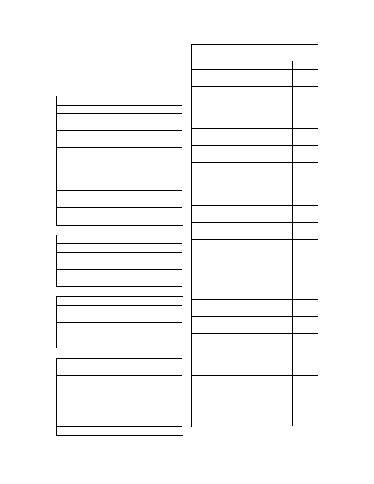
SPECIFICATIONS
1. OVERALL MACHINE INFORMATION
1.1. SPECIFICATIONS
Type
Desktop type transceiver
Circuit
PSTN, PABX
Connection
Direct couple
Document Size
Length: 105 - 600 mm [4.1 - 23.6 ins]
Width: 148 - 220 mm [5.8 - 8.7 ins]
Thickness: 0.05 to 0.15 mm [2 to 6 mils]
(equivalent to 50 - 80 g/m
Document Feed
Automatic feed, face down
ADF Capacity
15 sheets (using 20 lb. or 80 g/m
Scanning Method
Contact image sensor
Maximum Scan Width
216 mm [8.5 ins]
2
)
2
paper)
Transmission Time
9 s at 9600 bps; Measured with G3 ECM using memory for a ITU-T #1 test document
(Slerexe letter) at standard resolution
Printing System
Ink jet printing
Paper Size
Europe/Asia: A4
USA: Letter, Legal
Paper Capacity
150 sheets
Maximum Printing Width
203 mm [8.0 ins]
Maximum Printer Resolutions
Main scan: 360 dpi
(720 dpi in the printer mode)
Sub scan: 360 dpi
Power Supply
Europe/Asia: 220 - 240 Vac, 50 ± 3 Hz
USA: 115 ± 20 Vac, 60 ± 3 Hz
Scan Resolutions
Main scan: 8 dots/mm [203 dpi]
Sub scan:
Standard - 3.85 lines/mm [98 lpi]
Detail - 7.7 lines/mm [196 lpi]
Fine - 15.4 lines/mm [391 lpi]
Memory Capacity
ECM: 64 kbytes (single buffer) for tx
SAF: 400 kbytes
(272 kbytes for tx)
Compression
MH, MR, EFC, MMR, SSC (MMR only with
ECM)
Protocol
Group 3 with ECM
Modulation
V.29 (QAM), V.27ter (PHM), V.21 (FM)
Data Rate (bps)
9600/7200/4800/2400, Automatic fallback
Power Consumption
Standby: 5 W Transmit: 12 W
Receive: 14 W Copying: 24 W
Printer: 19 W
Operating Environment
Temperature: 17 - 28 °C [63 - 82 °F]
Humidity: 40 - 70 %Rh
Dimensions (W x D x H)
370 x 280 x 235 mm [14.6 x 11.0 x 9.3 ins]
Excluding handset, trays, and tables
Weight
Approx. 7 kg [15 lbs]
1-1
OVERALL MACHINE INFORMATION November 28th, 1995
FEATURES
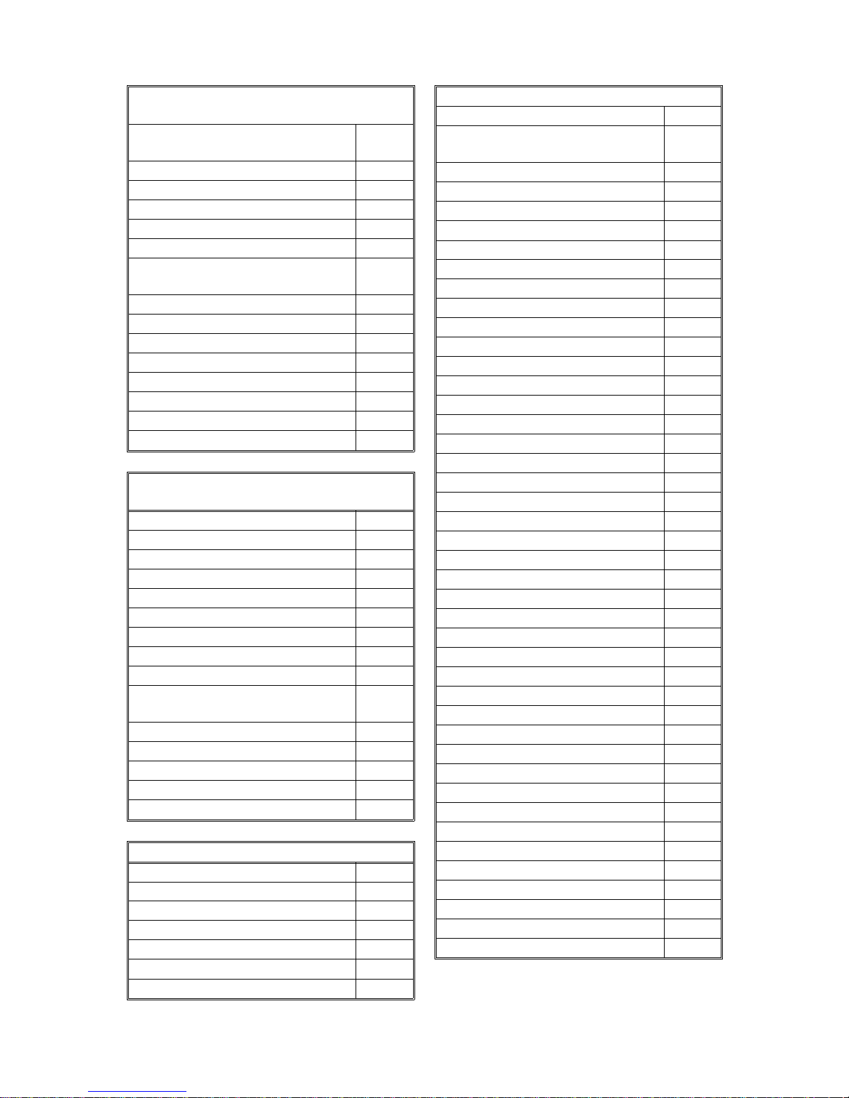
1.2. FEA TURES
KEY: O = Used, X = Not Used,
A = With optional memory only
B = With optional handset only
C = With color cartridge only
Equipment
ADF O
Book scan X
Built-in handset X
Bypass feed X
Optional cassette X
Cabinet X
Counter X
Cutter X
Handset (option) B
Hard disk X
Manual feed mechanism X
Marker (Stamp) X
Monitor speaker O
PC printer interface (IBM) O
Video Processing Features
Contrast X
Halftone (Basic & Error Diffusion) O
MTF O
Reduction X
Resolution O
Communication Features - Auto
Automatic fallback O
Automatic redialing O
Confidential reception A
Dual Access O
Substitute reception O
Communication Features -
User Selectable
Action as a transfer broadcaster X
AI Redial (last ten numbers) X
Answering machine interface O
Authorized Reception O
Auto-answer delay time X
Auto dialing (pulse or DTMF) O
Auto Document X
Communication Features -
User Selectable
Auto image density selection X
Auto paper size selection X
Automatic Voice Message X
Batch Transmis sion
(max 35 files)
Broadcasting O
Chain Dialing O
Communication Result Display X
Confidential ID Override O
Confidential Transmission O
Direct Fax Number Entry O
Economy Transmission X
Fax on demand X
Forwarding A
Free Polling O
Groups (3 groups) O
Group Transfer Station X
Hold X
ID Transmission O
Immediate Redialing O
Immediate transmission O
Keystroke Programs O
Memory transmission O
Multi-step Transfer X
Next Transfer Station X
OMR X
On Hook Dial O
Ordering Toner X
Page Count O
Personal Codes X
Personal Codes with Conf. ID X
Polling Reception O
Polling Transmission O
Polling tx file lifetime in the SAF O
Quick Dial (10 stations) O
Reception modes (Auto, Tel,
TAM)
Length Reduction (in Rx mode,
called Auto Reduction)
Remote control features X
Remote Transfer X
Restricted Access X
Secured Polling O
A
O
O
1-2
November 28th, 1995 OVERALL MACHINE INFORMATION
FEATURES
Communication Features -
User Selectable
Secured Polling with Stored ID
Override
O
Secure Transmiss ion X
Send Later O
Silent ringing detection X
Specified Image Area X
Speed Dial (50 stations) O
Super Fine Resolution
(16 x15.4 l/mm : 400 x 400 dpi)
X
Telephone Directory X
Tonal Signal Transmission O
Transfer Request X
Transmission Deadline (TRD) A
Turnaround Polling X
Two- step Transfer X
Two in one X
Voice Request (immed. tx only) X
Communication Features -
Service Selectable
AI Short Protocol O
Auto-reduction override option O
Busy tone detection O
Closed Network (tx and rx) O
Continuous Polling Reception X
Dedicated tx parameters O
ECM O
EFC O
Inch-mm conversion X
Page retransmission: no. of
times
O
Page separation mark O
Protection against wrong conn. O
Resol’n stepdown override option X
Short Preamble X
Well log X
Other User Features
Area code prefix X
Automatic service call X
Center mark X
Checkered mark X
Clearing a memory file O
Clearing a polling file O
Clock O
Other User Features
Confidential ID O
Copy editing (Erase Center/Mar-
gin)
Copy mode O
Copy Mode Restriction X
Counters O
Daylight Saving Time X
Destination Check X
Direct entry of names O
File Retention Time X
File Retransmission X
Function Programs X
ID Code O
Label Insertion ("From xxx") X
Language Selection O
LCD contrast control X
Memory Lock A
Memory Lock ID A
Modifying a memory file X
Multi Sort Document Reception A
Multicopy mode O
Own telephone number X
Power Saver X
Print density control X
Printing a memory file O
RDS on/off O
Reception Mode Switching Timer X
Reception time printing X
Reduction/Enlargement X
Remaining memory indicator O
Remote ID X
Reverse Order Printing A
RTI, TTI, CSI O
Secure ID X
Service Report Transmission X
Speaker volume control O
Specified Cassette Selection X
Substitute reception on/off O
Telephone line type O
Toner Saving Mode X
TTI on/off O
User Function Keys X
User Parameters O
Wild Cards O
X
1-3
OVERALL MACHINE INFORMATION November 28th, 1995
FEATURES
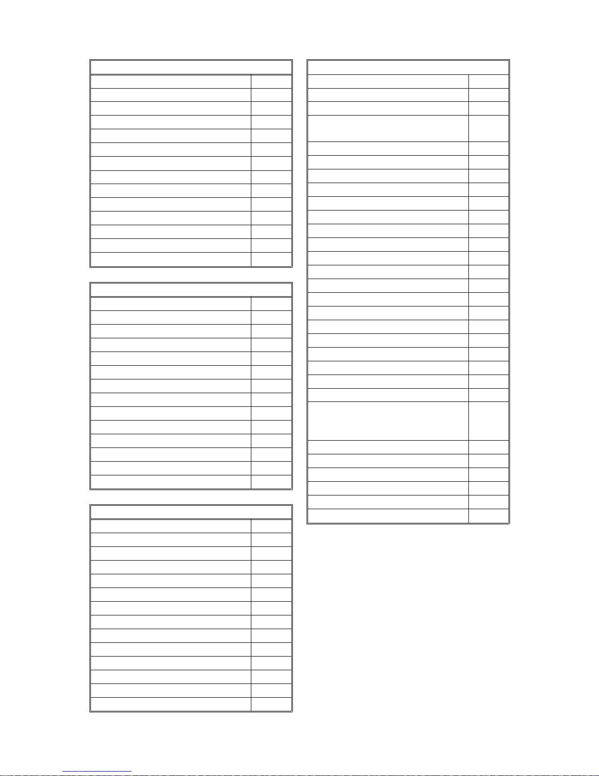
Reports - Automat ic
Charge Control Report X
Communication Failure Report O
Confidential File Report A
Error Report O
Memory Storage Report O
Mode Change Report X
Polling Clear Report X
Polling Reserve Report O
Polling Result Report O
Power Failure Report O
TCR (Journal) O
Toner Cassette Order Form X
Transfer Result Report X
Transmission Result Report O
Reports - User-initiated
Authorized Reception List O
Charge Control Report X
File List O
Forwarding List A
Group List O
Personal Code List X
Program List O
Quick Dial List O
Specified Cassette Selection List X
Speed Dial List O
TCR O
Transmission Status Report X
User Function List X
User Parameter List O
Service Mode Features
Auto Paper Select test X
Back-to-back test O
Bit switch programming O
Book mode test X
Buzzer test O
Cable equalizer O
Comm. parameter display O
Counter check O
Country code O
DTMF tone test O
Echo countermeasure O
Effective term of service calls X
Error code display O
Excessive jam alarm X
Service Mode Features
File Transfer O
LCD contrast adjustment X
Line error mark O
Memory file printout
(substitute reception only)
Modem test O
NCU parameters O
Operation panel test O
Periodic service call X
PM Call X
Printer mechanism test O
Printer test patterns O
Programmable attenuation X
Protocol dump list O
RAM display/rewrite O
RAM dump O
RAM test O
Ringer test X
Scanner lamp test O
Scanner mechanism test O
Sensor initialization X
Serial number O
Service monitor report O
Service station number O
Software upload/download
(Available only in machines with
the FLASH ROM.)
SRAM data download O
System parameter list O
Technical data on the TCR O
Thermal head parameters X
Transmission Status Report X
User data transfer O
Memory Files
Max. number of files: 100
Max. number of stations/ file: 100
O
O
1-4
November 28th, 1995 OVERALL MACHINE INFORMATION
COMPONENT LAYOUT
1.3. COMPONENT LAYOUT
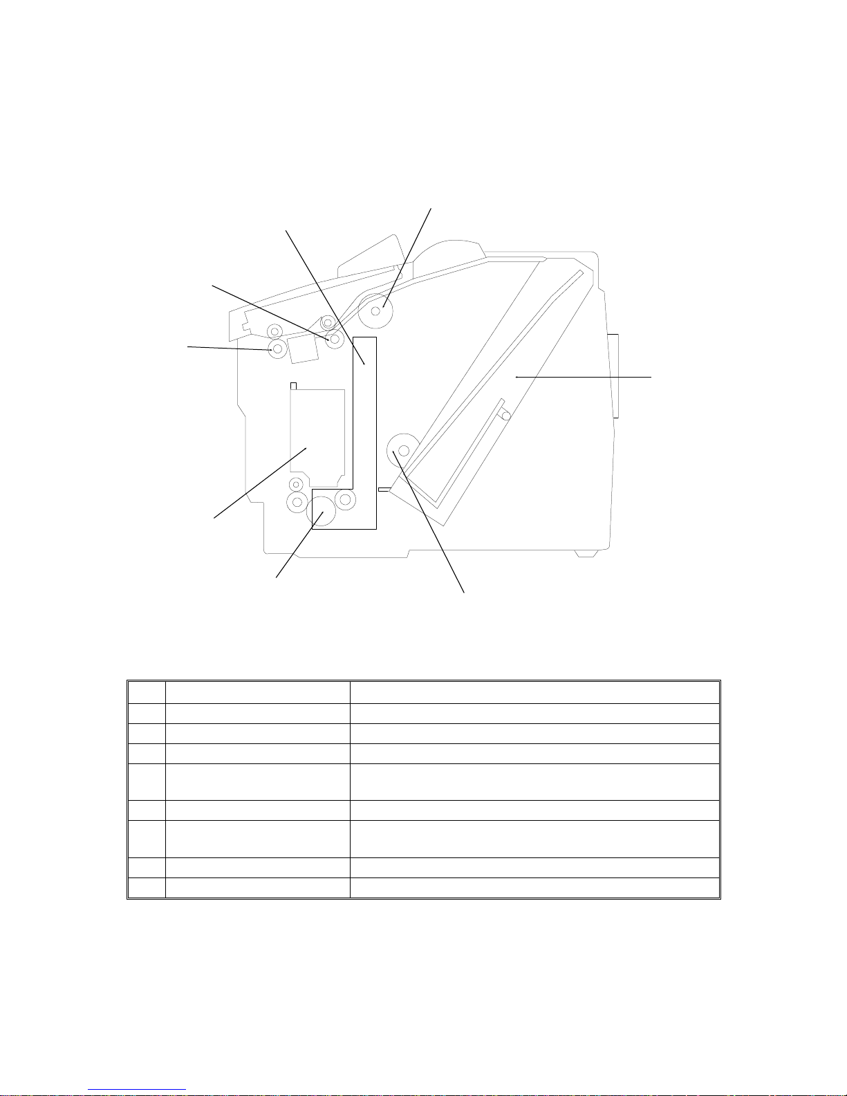
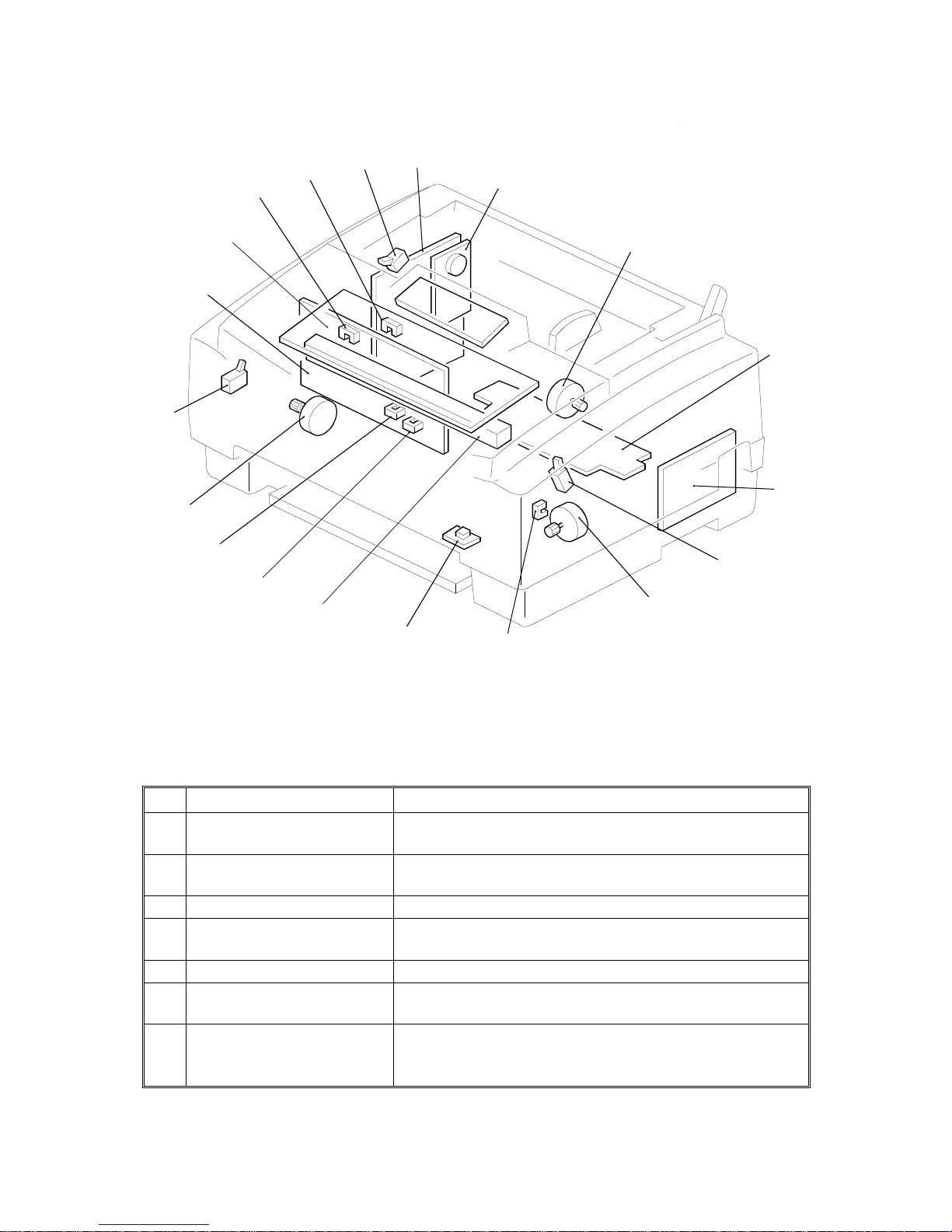
1.3.1. Mechanical Components
2
1
8
7
3
6
5
4
No. Name Descri ption
TIJ Thermal ink jet printer unit.
1
Document Feed Roller This roller feeds the document into the scanner.
2
Paper Feed Unit This unit can hold up to 150 sheets.
3
Paper Feed Roller This roller picks up the top sheet of paper, and feeds it
4
Registration Roller This roller carries out the registration process.
5
Carriage Unit / Ink
6
Cartridge
R2 Roller This roller feeds the document through the scanner.
7
R1 Roller This roller feeds the document through the scanner.
8
into the printer.
The carriage unit holds the ink cartridge. The cartridge
contains the ink jet printer head and the ink.
H505V501.wmf
1-5
OVERALL MACHINE INFORMATION November 28th, 1995
COMPONENT LAYOUT
1.3.2. Electrical Components
19
18
1
17
4
5
3
2
6
7
8
9
10
11
16
15
14
13
12
1. PCBs
No. Name Description
FDU (Facsimile Driver
1
Unit)
OPU (Operation Panel
2
Unit)
IJC (Ink Jet Controller) This board controls the ink jet printer.
6
FCE (Facsimile Control
7
Engine)
PSU (Power Supply Unit) This board supplies power to the machine.
9
NCU (Network Control
10
Unit)
Contact Image Sensor
Assembly
15
This board contains drivers for the motors, a dc-dc
converter, and the DRAM backup circuit.
This board controls the operation panel.
This board controls the machine. It contains the main
cpu, ROM, system RAM, and other control components.
This board contains a relay and switches to interface
the machine to the network.
This sensor reads and converts the light reflected from
the document into an analog video signal. It uses an
RLA (Rod Lens Arr ay) sens or unit.
H505V502.wmf
1-6

November 28th, 1995 OVERALL MACHINE INFORMATION
COMPONENT LAYOUT
2. Motors
No. Name Description
Tx Motor This stepper motor drives the scanner rollers.
8
Carriage Motor This motor drives the printer’s carriage mechanism.
12
Paper Feed Motor This motor drives the paper feed roller and the
18
registration roller.
3. Sensors
No. Name Description
Scan Line Sensor This sensor detects when the document approaches
3
Document Sensor This sensor detects the presence of a document in the
4
Top Cover Sensor This sensor detects whether the top cover is opened or
5
Paper Release Lever
Sensor
11
Carriage Home Position
13
Sensor
Ink End Sensor This sensor detects when the ink in the cartridge has
14
Paper Feed Roller Sensor This sensor detects the initial rotation position of the
16
Paper End Sensor This sensor detects the presence of paper in the printer.
17
Front Cover Sensor This sensor detects whether the front cover is opened
19
the scanning position.
feeder.
closed.
This sensor detects when the paper release lever is
released. (The paper release lever is also known as the
paper feed lever.)
This sensor detects when the carriage is at the home
position.
run out.
paper feed roller.
or closed.
1-7
OVERALL MACHINE INFORMATION November 28th, 1995
OVERALL MACHINE CONTROL
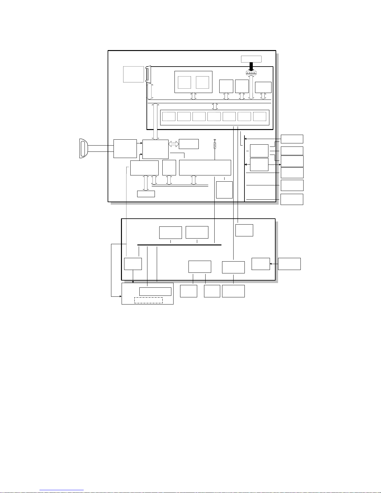
1.4. OVERALL MACHINE CONTROL
Optional
RS232C I/F
Centronics
Interface
Optional
IC Card
IJC
I/F
Controller
RIDC
Print
Controller
DRAM
FDU
FCE
MDM
FCIP
ROM
Paper Feed
Roller Sensor
DRAM
Working
ECM/
SAF
RAM
Memory
DATA/ADDRESS BUS
CPU
DMAC DCR DIP LIF
RU8
SRAM
CPU
Paper End
Sensor
System
ROM
Thermistor
EEPROM
System
RAM
(SRAM)
DRAM
Video
SRAM
PRIF
HIC
LED
Driver
NCU
Speaker
Contact Image
Sensor
Cover
Sensors
Ink End
Sensor
Operation
Panel
Heater
Drivers
Carriage
Printer Head
Cartridge
Detection
Home Position
Sensor
Type/
Color
Carriage
Motor
Drivers
Paper
Feed
Motor
Driver
Tx Motor
DC-DC
Converter
PSU
H505V504.wmf
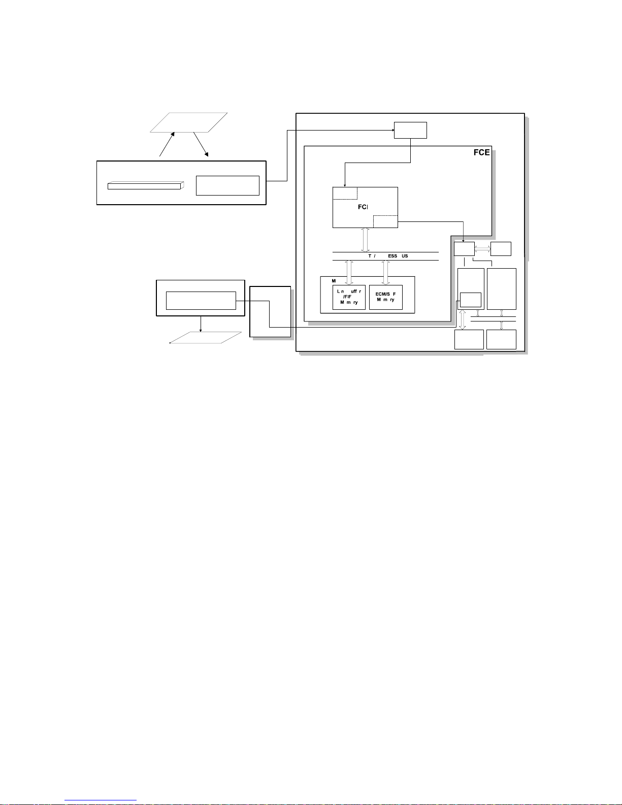
The FCE (Facsimile Control Engine) contains th e FCIP (Facsimile Control
and Image Processor), DRAM, SRAM, Syste m ROM, an d vide o processing
memory. It controls the entire system through the IJC (Ink Jet Controller) and
the FDU (Facsimile Driver Unit).
There are two cpus in the mach ine: the main cpu (FCIP) on the FCE an d th e
ink jet control cpu on the IJC.
The FCIP consist s of th e following component blocks:
• MDM - Modem• RU8 CPU - Main CPU
• PRIF - Printer Interface• DMAC - DMA Controller
• DIP - Digital Imag e Processor
• DCR - Data Compression and Recon-
struction
1-8

November 28th, 1995 OVERALL MACHINE INFORMATION
OVERALL MACHINE CONTROL
The 512 KB DRAM contains the SAF memory, ECM buffer memory, and work
area. The SAF memory can be exte nd ed by 2 or 4 Mbytes with an IC card.
A 512 KB (4 Mbit) ROM is used for the system ROM.
For the USA and some Europe models, th e sof tware in this ROM can be rewritten from the IC card slot or by RDS (because a Flash ROM is used ).
The IJC consists of the following compo ne nt s:
• CPU - 16-bit CPU with 16-MHz external clock input
• Printer Controller - Gate Array
• RIDC - Raster Image Data Controller, interface between FCE and IJC
• ROM - The inkjet printer control prog ram an d the bitmap font data
• DRAM - Receive buffer, download buffer, and working area for printing
• I/F Controller - Centronics Interface Controller
• SRAM - Working area
• HIC - Hybrid IC, Tx/Rx Amplifie r
• Thermistor - Detects the temperature in the print er
• LED Driver - LED on/off control
• EEPROM - Contains the following data:
• Total amount of waste ink
• Total number of pages that have passed throu gh the printer
mechanism
1-9
OVERALL MACHINE INFORMATION November 28th, 1995
VIDEO DATA PATH
1.5. VIDEO DATA PATH
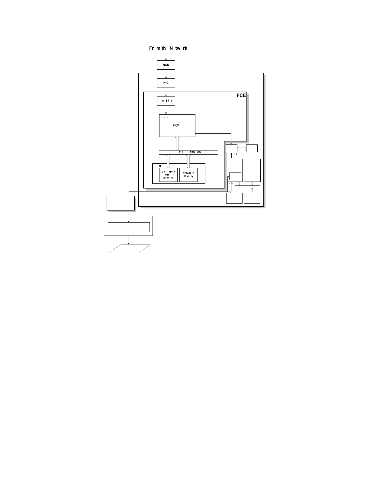
1.5.1. Transmission
Original
Contact Image Sensor Assembly
LED Array
Image Sensor
IJC
HIC
FCE
HIC
NCU
To the network
H505V505.wmf
SAF IC
Card
Video
Processing
Memory
DRAM
Memory
Line
Buffer/
FIFO
FCIP
DCR
DATA/ADDRESS BUS
ECM/SAF
Memory
DIP
MDM
Amplifier
Immediate Transmission:
Scanned data from the contact image sensor passes to the DIP blo ck in the
FCIP. After analog/digita l vide o p rocessing, the DCR block comp resse s t he
data for transmission . The compressed data then passes eit he r to the FIFO
memory or to the ECM memory, before it is sent to the telephone line through
the modem.
Memory Transmission:
First, the scanned data is stored in the SAF memory after compression in the
DCR block. At the time f or t ransmission, the DCR block decomp resse s t he
data from the SAF memory, then compresses it again after han dsh aking with
the other terminal is done. The compre ssed dat a th en pa sses e ith er t o t he
FIFO memory or to the ECM memory, before it is sent to the telephone line
through th e modem.
1-10
November 28th, 1995 OVERALL MACHINE INFORMATION
VIDEO DATA PATH
1.5.2. Reception
IJC
DCR
RIDC SRAM
Print
Controller
Print Head
Controller
CPU
FDU
Carriage
Printer Head
Copy Paper
DRAM ROM
H505V506.wmf
Data from the line p asse s to the modem throu gh th e NCU a nd hybrid IC. After the modem demodula tes the data, the data (which is compressed) passes
to the SAF memory. After the data has been stored in the SAF memory, it
passes through either t he FIFO or the ECM memory to the DCR block, where
the data is decompressed to rast er image data.
The image data is then passed to the Print Controlle r for printing, through th e
RIDC.
After the data has been stored in the DRAM (which acts as a print buf f er), the
data is sent to the printer head through the printer head cont rol blo ck.
1-11
OVERALL MACHINE INFORMATION November 28th, 1995
VIDEO DATA PATH
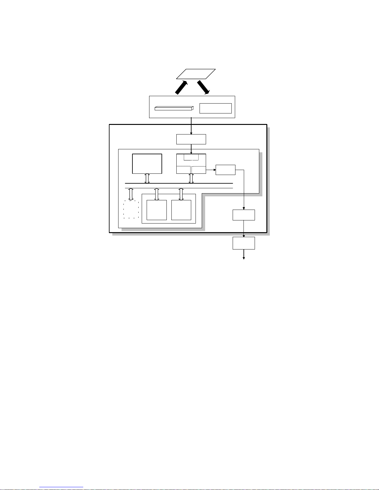
1.5.3. Copying
Original
Contact Image Sensor Assembly
Image Sensor
LED Array
Carriage
Printer Head
Copy Paper
FDU
HIC
DIP
DCR
IJC
RIDC SRAM
Print
Controller
Print Head
Controller
DRAM ROM
CPU
H505V507.wmf
Single copy
The scanned data is processed in the DIP block. After the da ta has been
stored in the DRAM for printing through the RIDC, the data is sent to the
printer head through the Print Controller.
Multi-page copy
The scanned data passe s t o th e SA F me mory af ter video processing (DIP)
and compression (DCR). After a pa ge of da ta has been stored in the SAF
memory, the data passes to the DCR block again for de compression, then it
passes to the print con tro ller for printing through th e RIDC.
1-12
November 28th, 1995 OVERALL MACHINE INFORMATION
VIDEO DATA PATH
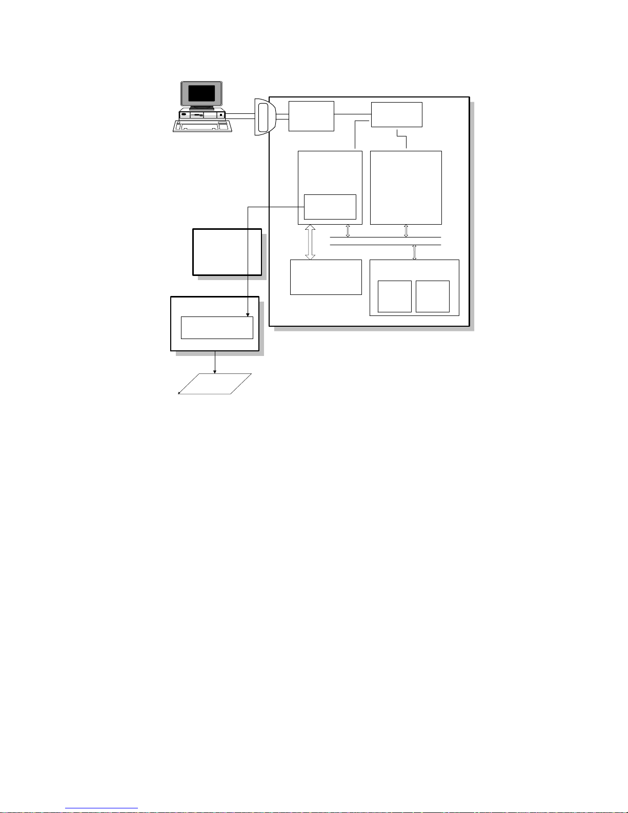
1.5.4. Printing from the Centronics Interface
Centronics
I/F
I/F
Controller
Print Controller
Printer Head
Controller
RIDC
CPU
FDU
Printer Control
Program
ROM
Bit Map Font
Data
DRAM
Carriage
Printer Head
Copy Paper
H505V508.wmf
The print data passes f rom th e Centronics interface to th e print controller
through the I/F controller and the RIDC.
The print data is stored in th e DRA M, which acts as a print buffer . At the
same time, font data from the ROM is stored in the DRAM, which also acts as
a downloaded font buffer if necessary.
After the print data has been stored with the font data in the print buffer, the
print data passes through the print er head cont rol block to the print controller
for printing.
1-13
OVERALL MACHINE INFORMATION November 28th, 1995
POWER DISTRIBUTION
1.6. POWER DISTRIBUTION
1.6.1. Distribution Diagram
PSU
Carriage
HVH
HVDD
+24VH
FDU
+24VM
+24VM
+24VH
+5V
Tx Motor
+5V
Driver
+24VM
DRAM Backup
Circuit
BAT
DC-DC
Converter
(for Stepping Motors)
Carriage
Motor
Drivers
+5V
-5V
+24VM
Paper Feed
Motor
+24VM
+5V
-5V
+24VM
Contact Image
DC-DC
Comverter
+24VM
-5V
Sensor
+5V
+5VBAT
+12VP
+5V
+5VCIS
+5V
FCE
+5VBAT
IJC
+5V
+5V
+24VM
Ink End
Sensor
Operation
Panel
NCU
H505V509.wmf
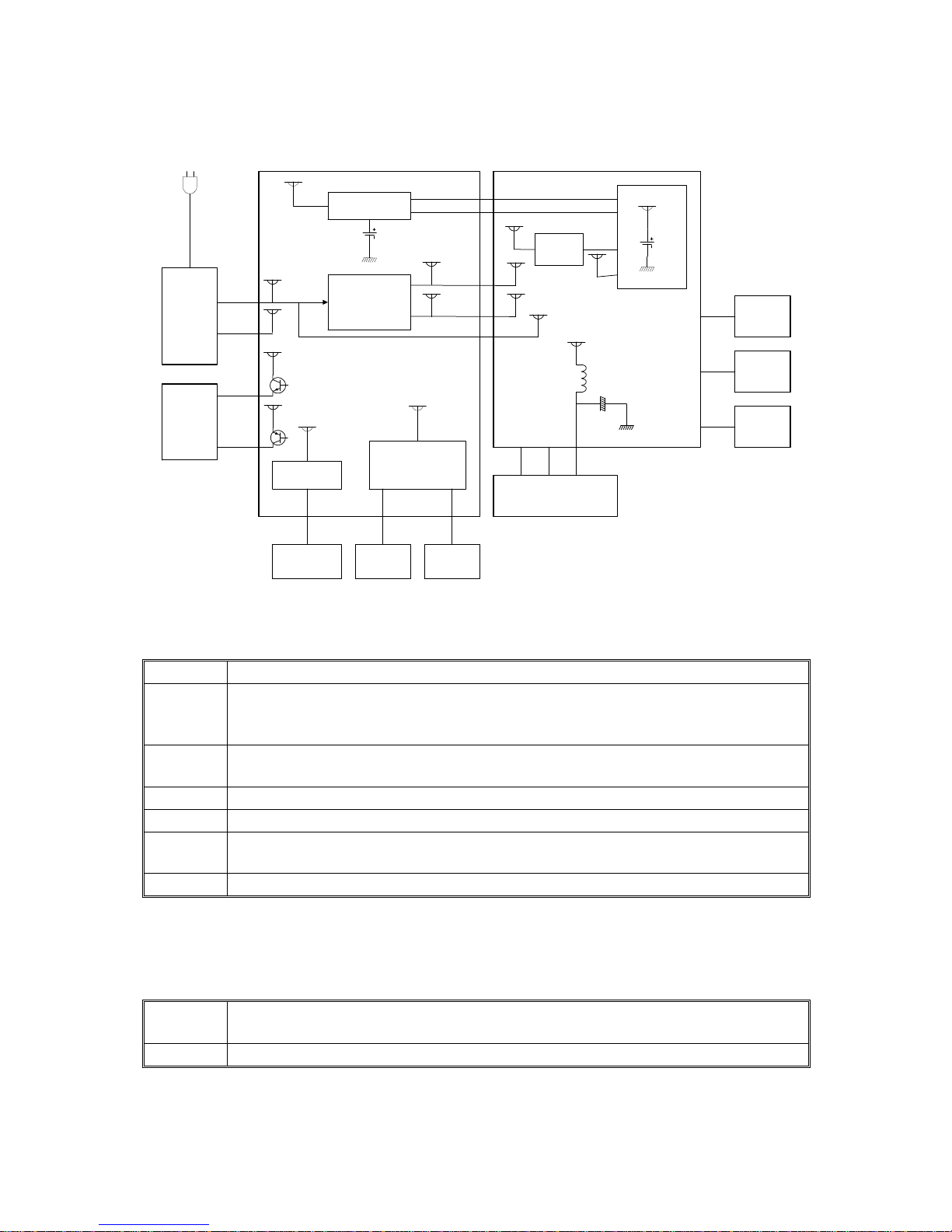
The PSU supplies +24V dc power to the FDU. The FDU co nve rts the +24V
dc power supply to the following supplie s.
+5V
This is normally on when the main power is supplied.
This supplies the DRAM and the optional IC card on the FCE to back up the
+5VD
stored data for one hour. A rechargeable battery on the FDU is used to
generate +5VD.
+5VBAT
+24VM
-5V
+24VH/
This supplies the system RAM on the FCE to back up the programmed data. A
lithium battery is used to generate +5VBAT.
This is normally on when the power code is plugged in.
This is used for the image sensor.
This is supplied to the temperature control heater on the printer head.
HVH
HVDD
This is supplied to the drive circuit on the printer head.
The FDU supplies + 24V and ±5V dc power to the IJC. The IJC converts the
+24V and +5V dc power supplies to the fo llowin g sup plie s.
+5VCIS
+12VP
This is a more stable power supply than +5V. It is used for the Contact Image
Sensor.
This is supplied to the Flash ROMs on the FCE and the optional IC card.
1-14

November 28th, 1995 OVERALL MACHINE INFORMATION
POWER DISTRIBUTION
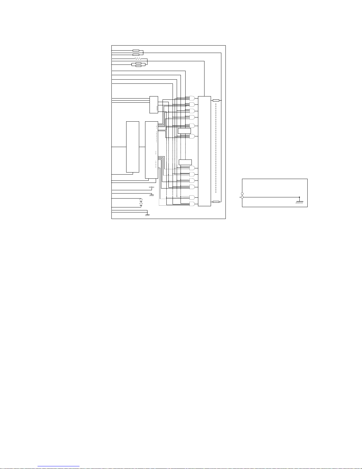
1.6.2. Memory Back-up Circuit
IJC
[A]
[B]
FDU
H505V510.wmf
The +5VBAT supply from the lithium bat te ry [A] backs up the system RAM
which contains system para met ers an d pro grammed telephone numbers,
and the real time clock in the main cpu. The 5R TCCS sig na l tells th e main
cpu whether the back-up powe r (+5 VB AT) is coming from the battery or from
the +5V power supply.
A rechargeable lithium batt ery [B] and the dc/dc converter on the FDU back
up the DRAM (SAF memory) for one hour. While the main power is on, the
+5V supply recharges th e ba ttery. The battery recharges in one or two days.
The battery [B] generat es abou t 3 volt s (max. 3. 2 vo lts). The dc/dc converter
(IC12) lifts this voltage to 5 volts so it can be used as the +5VD sup ply for
SAF backup. The CPU monit ors the voltage of the +5VD supply with the
1VDET signal. Whe n th e ba tt ery ha s run do wn, and the volta ge is lower t han
4.4 volts, the CPU stops the dc/dc converter by dropping 1SAFFG to low and
the machine stops backing up the memory.
There is no battery switch for the battery [B].
1-15
[D]
November 28th, 1995 DETAILED SECTION DESCRIPTIONS
SCANNER
2. DETAILED SECTION DESCRIPTIONS
2.1. SCANNER
2.1.1. Mechanisms
1. Document Detection, Pick-up and Separation and Dri ve Mecha nis m
[A]
[B]
[G]
A: Document Sensor
B: Scan Line Sensor
C: Separation Rubber Plate
E: Tx Motor
[C]
[E]
[F]
H505D501.wmf
The document se nso r [A] detects when a do cument is placed in the ADF. The
tx motor [E] then sta rts to prefeed the document unt il t he scan line se nso r [ B]
detects it. The separation rubb er pla te [C] pre vents the feed roller [D] from
feeding more than one sheet at a time.
To feed the document throught the scanne r, the Tx motor [E] dr ives t he feed
roller , the R1 roller [F], and the R2 roller [G].
2-1
[A]
[E]
DETAILED SECTION DESCRIPTIONS November 28th, 1995
SCANNER
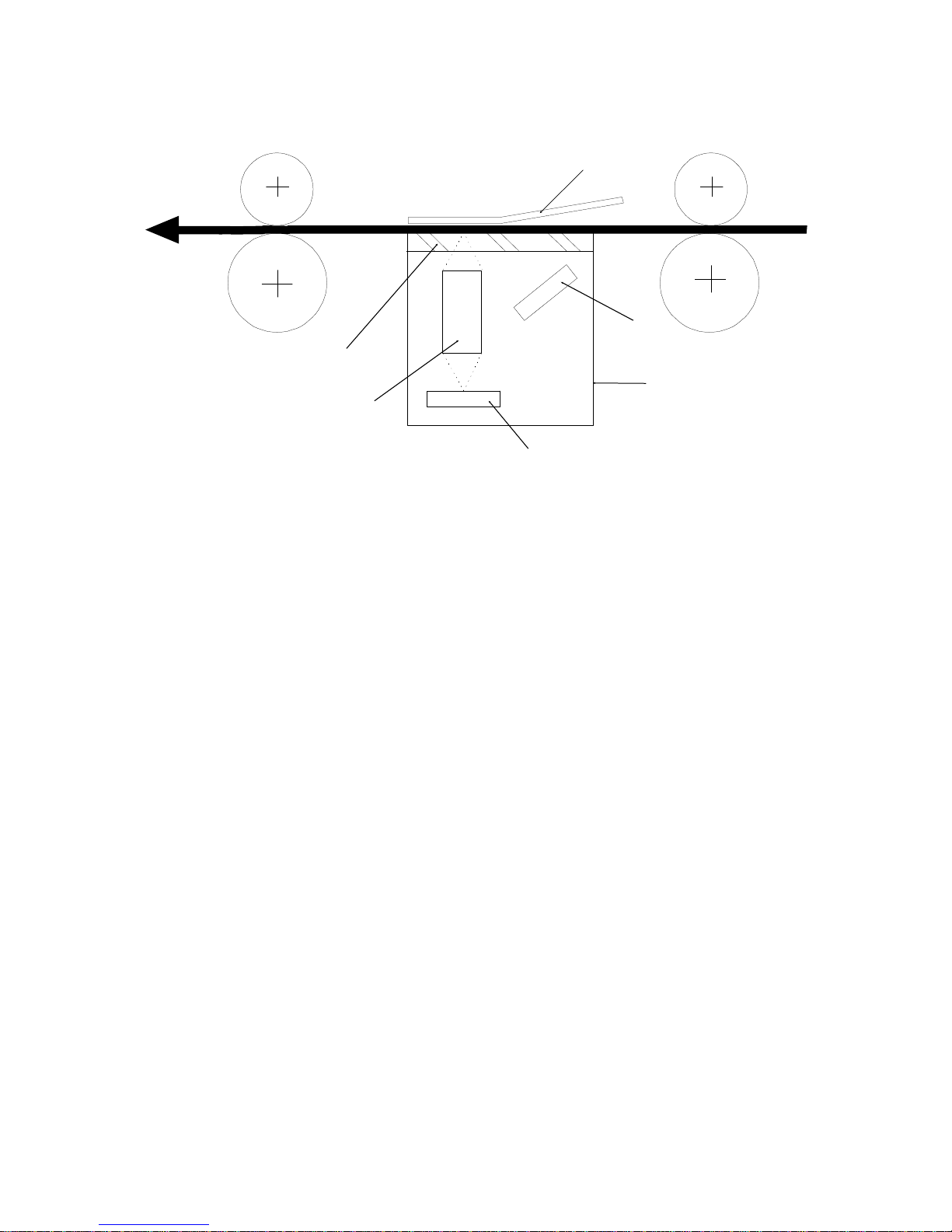
2.1.2. Image Scanning
[F]
[C]
[B]
[D]
H505D522.wmf
The scanner consists of a sha ding plate [A] and a contact image sensor
(CIS) assembly [B]. Insid e the CIS are an exposure glass [C], a rod lens array [D], an image sensor [E], and an LED array [F] .
The image sensor consists of a row of 1728 photo sensitive elements. Light
from the LED array is reflecte d from the document and focused onto the image sensor by the rod len s array. Because of the short optical path inside the
CIS, the focal depth is much short er than for a CCD type scanner. Because
of this, the shadin g plate pushes the document so that the document surface
always touches the exp osu re glass at the scan line.
The image sensor assembly is not adjusted at the factory, so it does not need
any adjustment at replacement in the field.
The image sensor scans the origin al on e line at a time, and outputs an analog signal for each line. The voltage from each element depends on the
intensity of the light reflected from the original onto the elemen t.
The machine feeds the document throug h the scanner using one of th e following step widths: th e scanned lines are transmitte d without any OR
processing.
3.85 lines/mm in Standard resolution
7.7 lines/mm in Detail resolut ion
15.4 lines/mm in Fine resolution
2-2

November 28th, 1995 DETAILED SECTION DESCRIPTIONS
SCANNER
Auto Contrast Thresholding
This machine determines the cont rast thresholds automatically whe n text
mode is used. The machine compares the video data ele men t with the surrounding elemen ts an d automatically calculates the threshold level.
When this mode is enabled, the contrast thresho ld set ting of scanner bit
switch 02 is ignored.
This function can be disable d with scann er bit swit ch 00.
Jam Conditions
The machine detect s a docu ment jam if one of the following cond itions occurs.
Jam Condition Description Error Code
The scan line sensor does not switch on within
Non-feed
Incorrect sensor
condition
3.0 s of the tx motor starting to prefeed the
document.
The scan line sensor does not turn off after the
maximum document length has been fed
since it turned on.
1-00
1-01
2-3
DETAILED SECTION DESCRIPTIONS November 28th, 1995
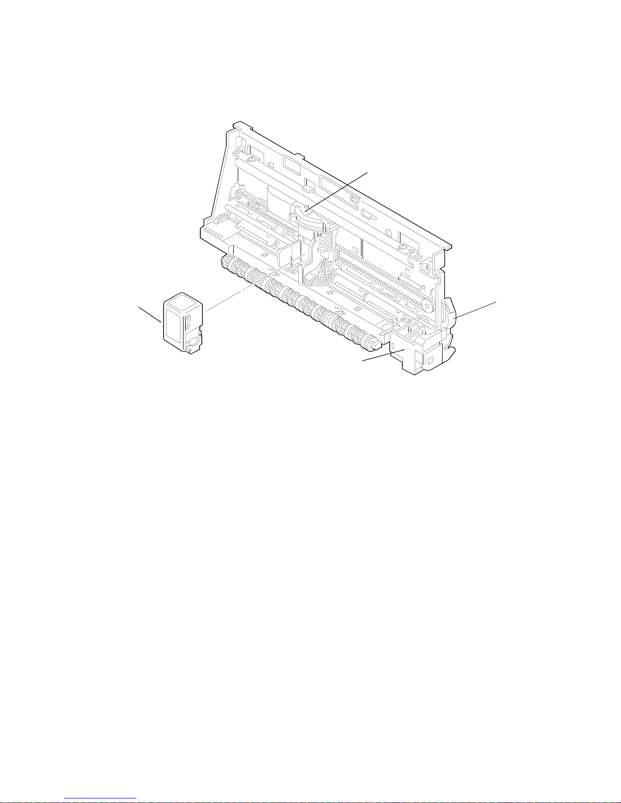
PRINTER
2.2. PRINTER
2.2.1. Printer Configuration
[C]
[A]
[D]
[B]
H505D512.wmf
Ink Cartridge [A]: The ink cartridge is ma de up of the printer head and the
cartridge body. The machine can use both black and color ink ca rtrid ge s.
The black ink cartridge is a single unit, but the color ink cartridge has separate ink refills (black and color) which can be replaced.
Purge Unit [B]: To sustain a high quality printing level, th e purge unit maintains the ink nozzles wit h a cap and wiper. The purge unit p rotects the
nozzles with the cap when the print er is not in use.
Carriage [C]: The carriage unit, driven by the carriage motor [D], moves horizontally across the print paper. The print signals are transmitte d t o t he ink
cartridge by the carriage ribbon cable. Whe n the carria ge unit is at home position, paper feed mot or drive can be transferred to the purge unit or the pap er
feed roller (see "Paper Feed - Drive Mechanism" for details).
2-4
[E]
November 28th, 1995 DETAILED SECTION DESCRIPTIONS
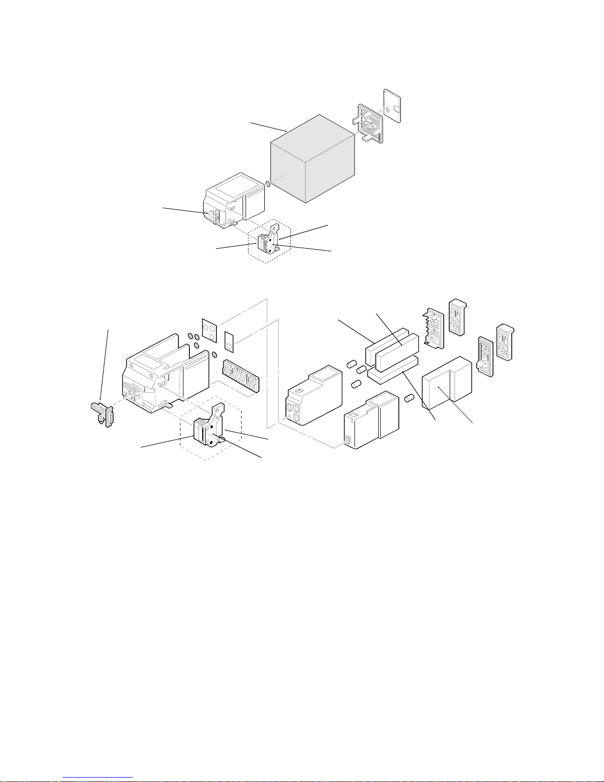
PRINTER
2.2.2. Ink Cartridge (Black and Color)
[A]
[H]
[I]
[F]
[D]
[J]
Black Ink Cartridge
H505D506.wmf
[C]
[H]
[B]
[I]
[G]
[J]
Color Ink Cartridge
H505D507.wmf
The black ink cartridge cont ains only the black ink sponge [A] while the color
cartridge contains ink sponge s for black [B], yellow [C], magenta [D], an d
cyan [E].
The black printer head face plat e [F] cont ain s a row o f 128 nozzles an d the
color printer head fa ce pla te [G] contains 136 nozzle s. In k passes to these
nozzles through an ink duct section [H]. Printing signals are sent to the printe r
head from the signal connection point [I].
2-5
Nozzle 136
DETAILED SECTION DESCRIPTIONS November 28th, 1995
PRINTER
2.2.3. Printer Head
1. Mechanism
[C]
[D]
[E]
[F]
[B]
[A]
H505D508.wmf
Ink from the sponge is filtered at [A] to remove dust, and then passes to the nozzles throug h pip e [B ]. W hen th e he ad dr ive cur re nt f low s thr ough a n ozzle ’s
heater plat e [C], th e ink at the plat e boil s. The bubb les for med [ D] even tuall y joi n
into one large bub ble [E] . The bubbl e forces a dro p of ink [F ] out of the nozzl e.
Head drive current stops before the bubble is fully formed. The remaining
heat of the heat plate complete s the bubble . The pla te cools b y th e t ime t he
ink drop is ejected, and fresh ink ent ers th e no zzle fro m t he spon ge .
The nozzles are arranged in a
straight line at intervals of 1/360
Nozzle 1
Nozzle 1
inch.
There are 128 nozzles in the
black ink cartridge.
The color ink cartridge has a
total of 136 nozzles: 24 yellow
Yellow 1~24
Magenta 25~48
Cyan 49~72
Black 73~136
nozzles, 24 magenta no zzles, 24
cyan nozzles, and 64 black nozzles.
Nozzle 128
Black Ink Cartridge Color Ink Cartridge
H505D509.wmf
2-6
ID0
ID1
November 28th, 1995 DETAILED SECTION DESCRIPTIONS
PRINTER
2. Drive Circuitry
Temperature Control Heater x 2
Rank Resistor
Sub-heater x 2
H ENB
Odd ENB
Even ENB
RANK
WH-T
HTO
HVH
HTI
VHG
<0>
<1>
128/136
Bit Tr.
Array
Heater 1
Heater
128/136
*
B ENB
HDATA
HCLOCK
HLATCH
DIODE A
DIODE K
HRES
HVdd
HVss
<0>
<1>
<2>
Decoder
128/136
Bit Shift
Register
ID0
ID1
3→8
128/
136
/
Temperature
128/136
Bit Latch
Head
Sensor
1
2
8
1
16
113
114
128/
136
Delay
Delay
H505D504.wmf
128/136 Bit Shift Register: This register store s the print data (HDAT A) sent
from the FCE with the HCLOCK timing signal.
128/136 Bit Latch: This latch sto res th e prin t data (HDATA) sen t from the
128/136 bit shift registe r with th e HLATCH timing signal.
3→8 Converter: This converts the three BENB (block enable) signals (<0>,
<1>, and <2>) into the 8-division timing signals for all heat ers.
Heaters 1-128/1-136: These heaters heat the nozzles. They are turned on
by a combination of OddENB or Eve nENB, HENB (heat enable), the timing
signals from the 3→8 converter, and the data signal (HDAT A ) from the latch.
Sub-heater: This heater keeps the ink in the nozzles warm.
Temperature Control Heater: This heater stabilizes the amo un t of in k in-
jected.
Heat Temperature Sensor: This sensor use s a diode to detect the t empera-
ture variation caused by th e flo w of ink at the nozzle s.
Cartridge ID: The cart ridg e typ e (color or black) is det ect ed with the I D0 a nd
ID1 signals.
*These ID signals identify a color cartridge.
The main illustration’s ID signals identify a black cartridge.
2-7
DETAILED SECTION DESCRIPTIONS November 28th, 1995
PRINTER
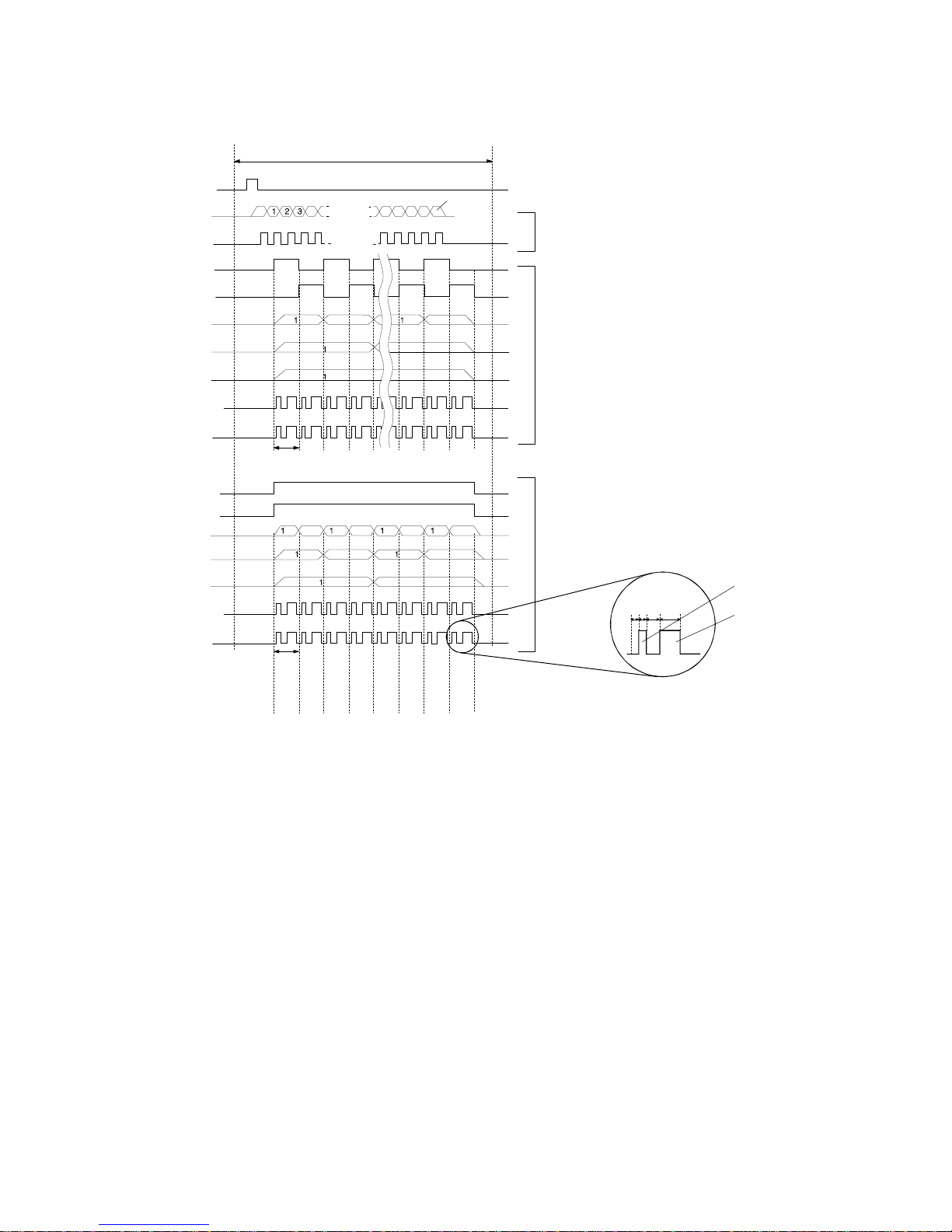
3. Print Signals
HQ 160s (6.25kHz)
Smoothing 128s (7.81kHz)
HS 112s (8.93kHz)
HLATCH
HDATA
HCLOCK
Odd ENB
Even ENB
B ENB 0
B ENB1
B ENB 2
H ENB 0,1,2
H ENB 3
Odd ENB
Even ENB
B ENB 0
B ENB 1
B ENB 2
H ENB 0,1,2
1 BLOCK
128 OR 136
Data transmission to shift
Head Driving in HQ Mode
Head Driving in HS Mode
register
(Divided into 16)
(Divided into 8)
Variable
Pulse Width
Pre-Pulse
Main Pulse
H ENB 3
1 BLOCK
H505D510.wmf
The 3→8 convert er changes the three signa ls, BENB 0, 1, and 2, into 8 signals, dividing the nozzles into 8 blocks. For HQ print mode, these blocks are
then further divided with the OddENB and EvenENB signals into 16 nozzle
groups.
The HENB signals make up the pre-pulse s (wh ich raise the temp era tu re of
the printer head to a suitable te mpe rat ure), and the main pulses (which cause
the ink to be ejected). These signals are input with the print data signals for
each nozzle into th e A ND circuits (see the diagram on the pre vious page).
The resulting signal drive s the hea te rs.
2-8
[C]
November 28th, 1995 DETAILED SECTION DESCRIPTIONS
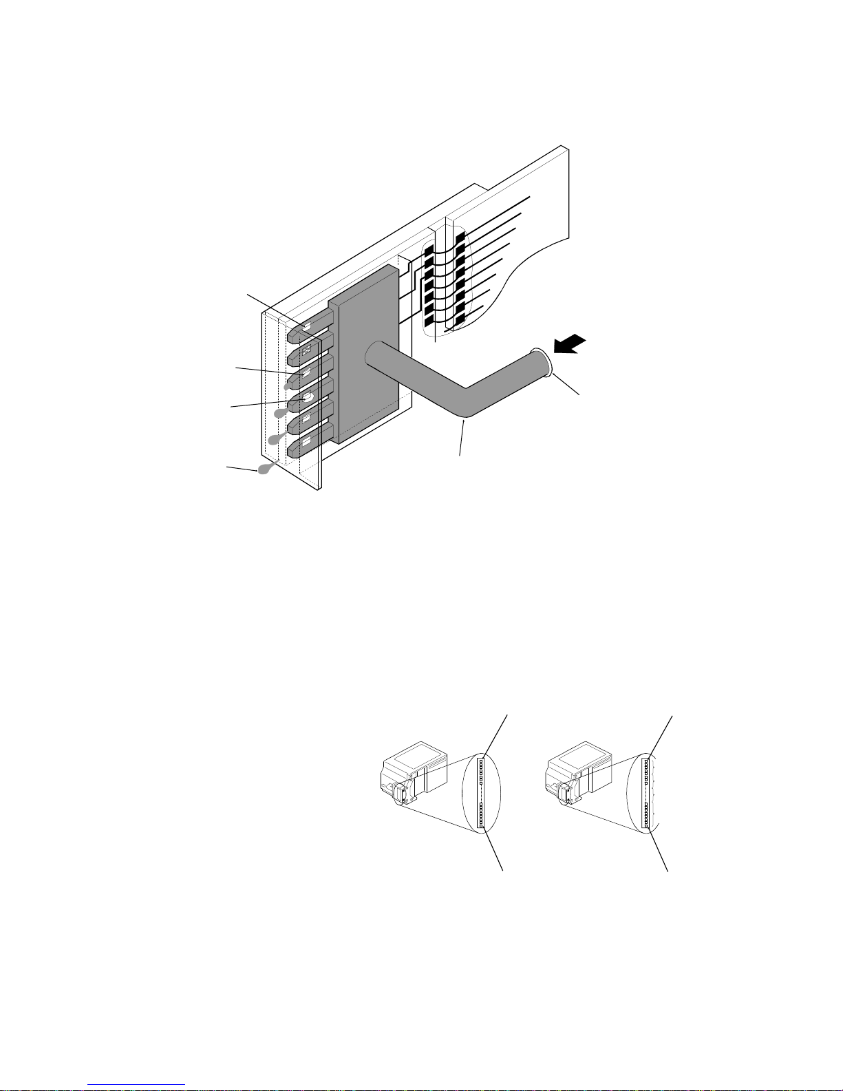
PRINTER
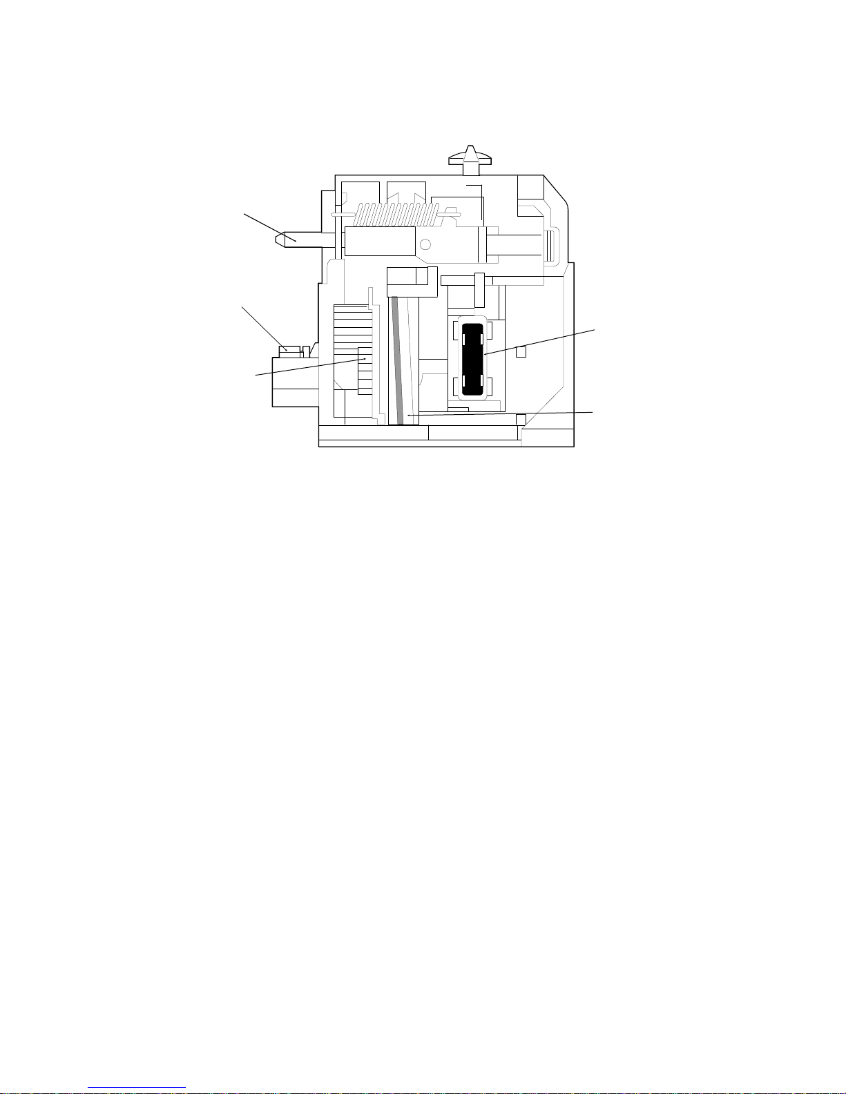
2.2.4. Purge Unit
1. Components
[E]
[A]
[D]
[B]
H505D51 1.wm f
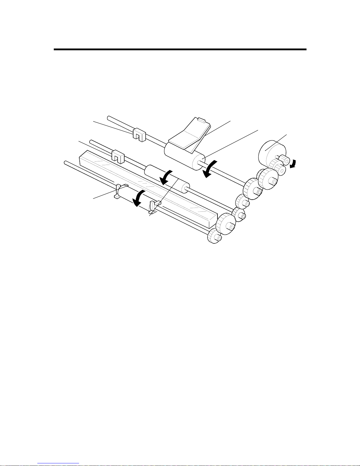
Purge Unit Drive Gear [A]: The paper feed motor drives this gear during
cleaning. The gear functions as a cam to control the ink p ump inside the
purge unit.
Wiper Unit [B]: The wip er unit wipes the ink from the ink cartridge face plate
during cleaning.
Cap Unit [C]: The cap unit caps t he print head fa ce plat e (n ozzle s) when the
nozzles move to the capping posit ion (this is when the carriage is at home position). The cap unit is also connect ed to th e ink pump. It extracts ink from
the ink cartridge during clea nin g op era tions. The waste ink is drained do wn
into the waste ink absorbers in the bottom of the unit.
Maintenance Jet Receiving Section [D]: This section receive s ink e ject ed
from the nozzles into the pu rge unit to prevent cloggin g. The g ea r fe ed s the
waste ink to the waste ink ab sorb ers in the bottom of the unit.
Slide Pin [E]: The slide pin causes the cap unit [C] to cap the nozzles when
the cartridge moves into the capping position. This unlo cks th e d rive transfer
mechanism inside the purge unit, allo wing the paper feed moto r drive to be
transferred eith er to the purge unit drive gear [A] or to the pa pe r f ee d unit
(see section 2-2-5).
2-9
 Loading...