

Ricoh FW870 SAFETY NOTICES

IMPORTANT SAFETY NOTICES
PREVENTION OF PHYSICAL INJURY
1. Before disassembling or assembling parts of the copier and peripherals,
make sure that the copier power cord is unplugged.
2. The wall outlet should be near the copier and easily accessible.
3. Note that some components of the copier and the paper tray unit are
supplied with electrical voltage even if the main switch is turned off.
4. If any adjustment or operation check has to be made with exterior covers
off or open while the main switch is turned on, keep hands away from
electrified or mechanically driven components.
5. The inside and the metal parts of the fusing unit become extremely hot
while the copier is operating. Be careful to avoid touching those
components with your bare hands.
6.The copier is not attached to the table. Pushing the copier too heard may
cause it to drop onto the floor. While moving the copier, push the table.
7. When the main switch is tuned on, the machine will suddenly start turning
to perform the developer initialization. Keep hans away from any
mechanical and electrical components during this period.
HEALTH SAFETY CONDITIONS
1. Never operate the copier without the ozone filters installed.
2. Always replace the ozone filters with the specified ones at the specified
intervals.
3. Toner and developer are non-toxic, but if you get either of them in your
eyes by accident, it may cause temporary eye discomfort. Try to remove
with eye drops or flush with water as first aid. If unsuccessful, get medical
attention.
OBSERVANCE OF ELECTRICAL SAFETY STANDARDS
1. The copier and its peripherals must be installed and maintained by a
customer service representative who has completed the training course
on those models.
CAUTION
2. The RAM board on the main cont rol board has a lithium battery
which can explode if replaced incorrectly. Replace the RAM board
only with an identical one. The manufacturer recommends
replacing the entire RAM board. Do not recharge or burn this
battery. Used RAM board must be handled in accordance with
local regulations.

SAFETY AND ECOLOGICAL NOTES FOR DISPOSAL
1. Do not incinerate the toner cartridge or the used toner. Toner dust may
ignite suddenly when exposed to open flame.
2. Dispose of used toner, developer, and organic photoconductor according
to local regulations. (These are non-toxic supplies.)
3. Dispose of replaced parts in accordance with local regulations.
4. When keeping used RAM boards in order to dispose of them later, do not
put more than 100 RAM boards per sealed box. Storing larger numbers
or not sealing them apart may lead to chemical reactions and heat
build-up.

SECTION 1
OVERALL
MACHINE INFORMATION

25 July 1996 SPECIFICATIONS
1. SPECIFICATIONS
Configuration: Console
Copy Process: Electrostatic transfer system
Original Feed: Sheet feed
Original Size: Maximum: 914 x 3,600 (36" x 142")mm
Minimum: 182 x 257 (B5), 8
Copy Size: Same as "Original Size"
Copying Speed: 7.5 cpm (A1/D sideways)
First Copy: 18 seconds (A1/D sideways)
1/2
" x 11" lengthwise
Overall
Information
Warm-up Time: Within 6 minutes (Room temperature 23
o
C)
Multi-Copy: 1 to 10
Automatic Reset: 2 minutes after copying is finished (can be set
to 1, 3, 4, or 5 minutes or to no auto reset)
Photoconductor: Organic photoconductor drum
Drum Charge: Single-wire with grid plate (Negative Charge)
Reproduction Ratio: 1 : 1 (
0.5%)
±
Exposure System: Slit exposure via fiber optic array
Exposure Lamp: Fluorescent lamp (26 W)
Development: Dual-component dry toner system
Toner Replenishment: Cartridge system (750 g toner/cartridge)
Toner Consumption: 1,860 A1 or D copies per cartridge (6% original)
Development Bias: Negative
Toner Density Control: Direct toner density detection by induction
sensor
Image Density Adjustment: Development bias control + exposure control
Auto Image Density Control: Development bias control + exposure control
Paper Separation: Dual wire ac corona and pick-off pawls
Cleaning: Cleaning blade
1-1

SPECIFICATIONS 25 July 1996
Paper Feeding: Manual feed and 2 roll feeds
(3rd roll feeder optional)
Image Fusing: Heat and pressure type, teflon (upper) and
silicone rubber (lower) rollers
Fusing Lamp: Halogen lamp
(115 V: 1,100 W, 230 V: 1,100 W)
Self-diagnostic Codes: 18 codes, displayed in copy counter
Power Source: 115 V/60 Hz....12 A
220 V/50 Hz....7 A
230 V/50Hz.....7 A
240 V/50 Hz....7 A
Power Consumption: Maximum: 1.41 kW
Warm-up: 1.21 kW
Ready: 0.1 to 1.2 kW
Copy cycle: 1.36 kW
Dimensions (W x D x H): 1230 x 690 x 1065 mm
48.4" x 27.2" x 41.9"
Weight: 195 kg, 429 lb
Optional Equipment and Machine Configuration
Configuration
Main frame Optional equi pm ent
A174
copier
3rd Roll feeder (A613) –
Side gui des (A569) –
Additional equi pm e nt
Other Optional Equipment
Paper Spool (Spare parts)
•
Key Counter Bracket Set (A902-15)
•
Key Counter (Procured locally)
•
Key Counter Holder (Procured locally)
•
Specifications are subject to change without notice.
1-2
25 July 1996 PAPER PATH
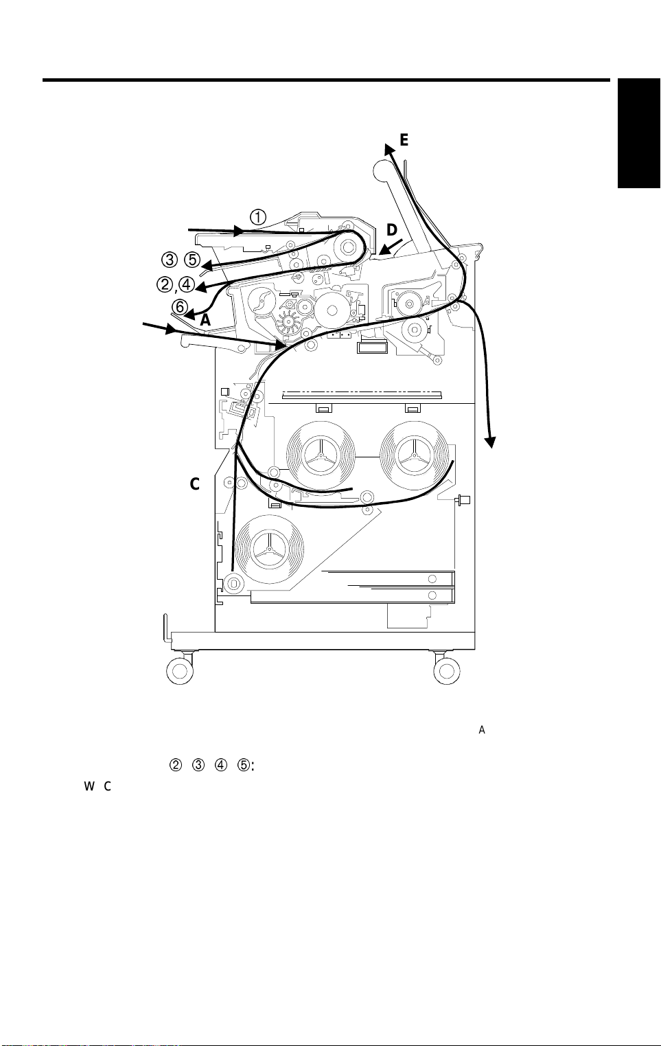
2. PAPER PATH
E
Overall
Information
D
,
,
B
A
F
C
A: Original Path , , , :
Switching back
B: Paper from the manual feed
C: Paper from the roller feed
A174V502.wmf
D: Original Path from Rear Feeder
E: Upper Copy Exit
F: Lower Copy Exit
1-3
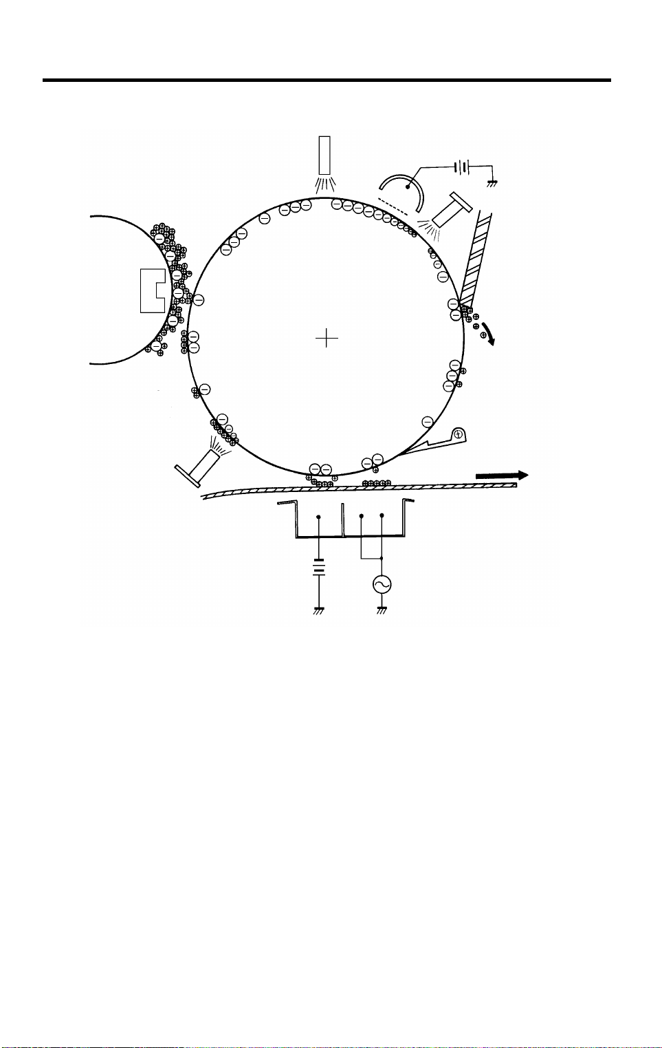
DRUM PROCESSES 25 July 1996
3. DRUM PROCESSES
2
1
8
7
3
4
5
6
A174V503.img
1. Charge
In the dark the charge corona unit applies a negative charge to the drum.
The grid plate ensures the charge is applied uniformly. The charge remains
on the surface of the drum because the photoconductive drum has a high
electrical resistance in the dark.
2. Exposure
High intensity light from a fluorescent lamp is reflected from the moving
original through the fiber optic array. The charge on the drum surface is
dissipated in direct proportion to the intensity of the reflected light, thus
producing an electric latent image on the drum surface.
1-4

25 July 1996 DRUM PROCESSES
3. Development
The magnetic developer brush on the development roller comes in contact
with the latent image on the drum surface. Toner particles are
electrostatically attracted to the negatively charged latent image areas.
4. Pre-Transfer Lamp
The pre-transfer lamp (PTL) illuminates the drum prior to image transfer. This
reduces the attraction between the toner and the drum, thus making image
transfer easier.
5. Image Transfer
Copy paper is fed to the drum surface, at the exact timing, to align the copy
paper and the developed image on the drum surface. Then a strong negative
charge is applied to the back side of the paper. The negative charge pulls
the toner particles from the drum surface onto the paper.
6. Paper Separation
A strong ac corona discharge is applied to the back side of the copy paper,
reducing the charge on the paper and breaking the electrostatic attraction
between the paper and the drum. Then, the stiffness of the copy paper
causes it to separate from the drum. The pick-off pawls help to separate
paper which has low stiffness.
Overall
Information
7. Cleaning
The cleaning blade, which is angled against drum rotation (counter blade
system), removes any toner remaining on the drum surface.
8. Quenching
The light from the quenching lamp electrically neutralizes the surface of the
drum.
1-5
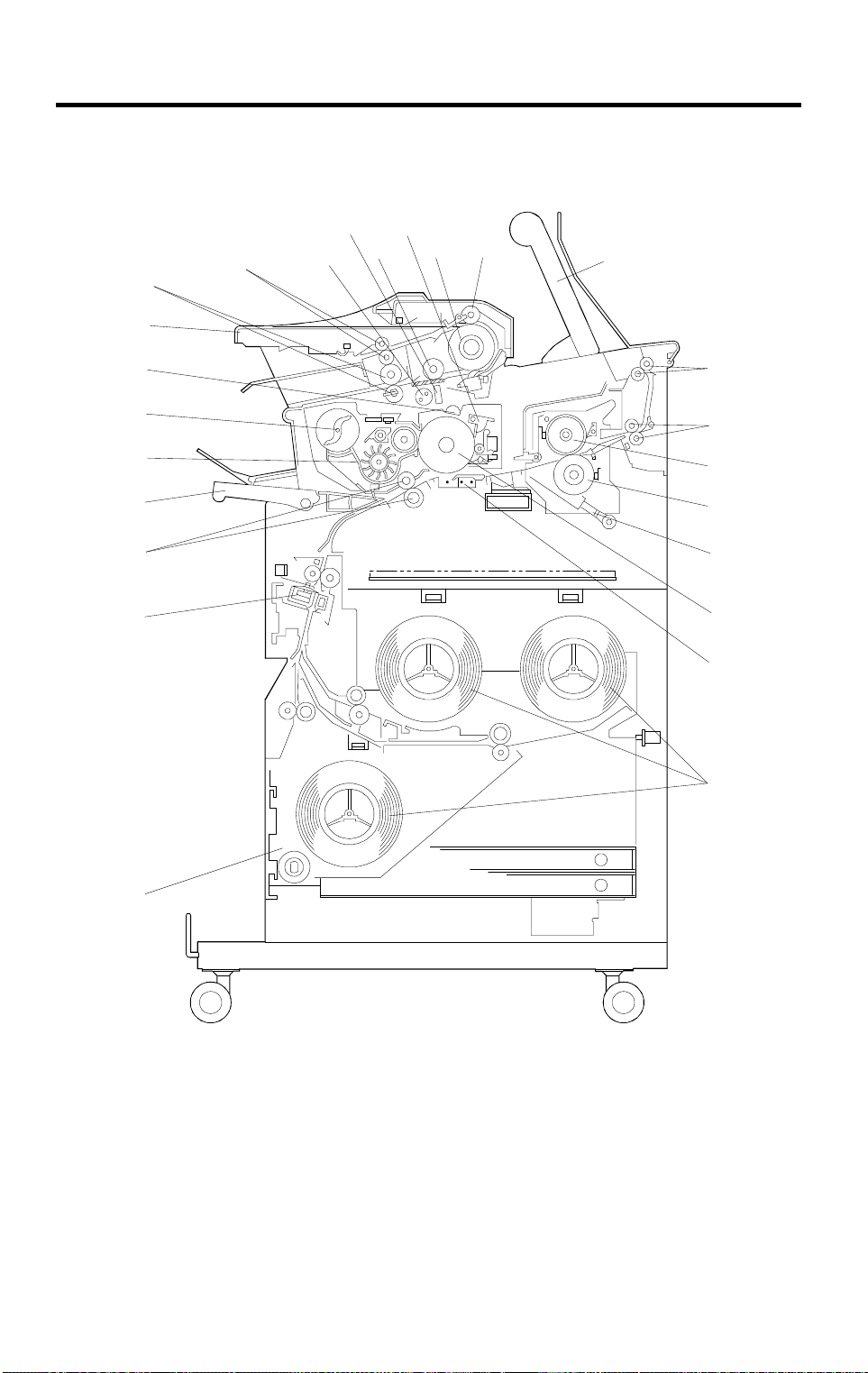
MECHANICAL COMPONENT LAYOUT 25 July 1996
4. MECHANICAL COMPONENT LAYOUT
20
19
18
17
16
15
14
13
21
22
23
24
25
1
2
3
4
5
6
7
8
9
10
12
11
A174V500.wmf
1-6

25 July 1996 MECHANICAL COMPONENT LAYOUT
1. Original Registration Roller
2. Original Feed Roller
3. Copy Tray
4. Exit Rollers
5. Fusing Exit Rollers
6. Hot Roller
7. Pressure Roller
8. Gas Spring
9. OPC Drum
10. T/S Corona Unit
11. Paper Spool
12. 3rd Roll Feeder
13. Cutter Unit
14. Paper Registration Rollers
15. Manual Feed Table
16. Development Unit
17. Toner Cartridge
18. Charge Corona Unit
19. Original Table
20. Origin al Ex it Rollers
21. Original Repeat Roller
22. Exposure Lamp
23. Fiber Optic Array
24. Platen Roller
25. Cleaning Blade
Overall
Information
1-7
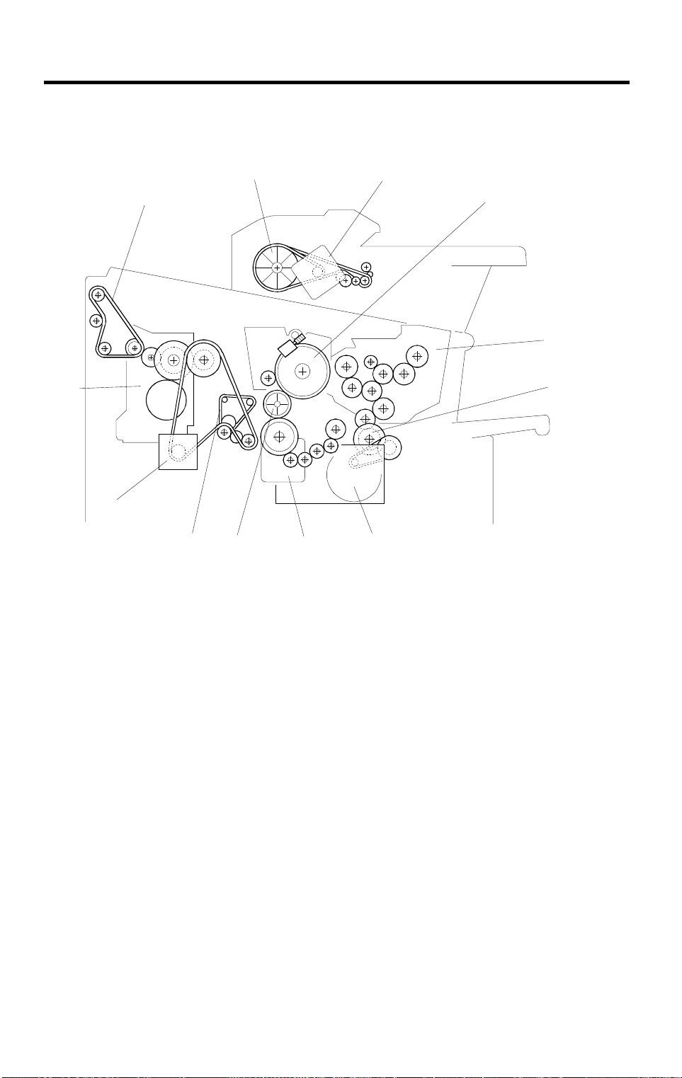
DRIVE LAYOUT 25 July 1996
5. DRIVE LAYOUT
10
12
11
1
2
3
4
9
8
7
6
5
A174V501.wmf
1. Original Feed Motor
2. Drum
3. Development Unit
4. Development Relay Gear
5. Development Motor
6. Main Motor
7. Drum Drive Relay Gear
8. Transport Unit Drive Belt
9. Fusing Drive Motor
10. Fusing Unit
11. Exit Unit D r iv e Be lt
12. Original Feed Drive Pulley
1-8

25 July 1996 ELECTRICAL COMPONENT DESCRIPTIONS
6. ELECTRICAL COMPONENT DESCRIPTIONS
Refer to the electrical component layout on the reverse side of the Point to
Point (Water proof paper) index numbers.
Name Function Index No.
Motor
Main Motor Drives the drum and the registrat i on r oll er . (dc mo tor) 20
Development Motor Drives the develo pm ent unit compon ent s. (d c m ot or ) 22
Fusing Driv e M ot or Drives the fusin g uni t com ponents. (dc mo to r) 2
Original Feed Motor Drives original feed rollers. (dc motor) 25
Roll Feed Moto r Drives the 1st, 2nd and 3r d r oll fe ed r oll er s. (d c m otor ) 52
Cutter Motor Drives the roll cutter. (dc motor) 56
Exhaust Fan Motor
Vacuum Motor 1
Vacuum Motor 2
Wire Cleaner Mo to r Drives the wire cleaner. 24
Magnetic Clutches
Roll Feed Clutch 1
Roll Feed Clutch 2
Roll Feed Clutch 3
Registrati on C lut ch
Toner Supply Clut ch Turns on to supply toner to the development unit . 21
Solenoids
Pick-off Pawl
Solenoid
Exit Gate Solenoid Moves the exit gate to change paper path . 12
Original Gate
Solenoid
Switches
Main Switch Supplies power to enable copy oper at ion. 37
Exit Cover Open
Switch
Left Cutter Switch
Right Cutter Switch
3rd Roll Feed Door
Open Switch
Upper Unit Safety
Switch
Removes the ozone bui lt up ar ound the drum sectio n
to the ozone filter. (dc motor)
Provides suction so paper is held firml y on t he
transport belt.
Provides suction so paper is held firml y on t he
transport belt.
Transmits the roll feed motor drive to the 1st roll feed
roller.
Transmits the roll f eed mo to r dri ve to the 2nd roll feed
roller.
Transmits the roll f eed mo to r dri ve to the 2nd roll feed
roller.
Transmits the main motor drive to the registration
roller.
Moves the pick-off pawls again st the drum. 66
Moves the origina l gat e to chan ge or i ginal path. 1
Detects whether the exit cover is open or not . 33
Detects whether the cutter unit is at the left home
position or not.
Detects whether the cutter unit is at the right home
position or not.
Detects whether the 3rd roll f eed door is open or not. 53
Cuts ac power when the upper unit is open. 38
7
19
10
55
58
54
23
57
50
Overall
Information
1-9

ELECTRICAL COMPONENT DESCRIPTIONS 25 July 1996
Name Function Index No.
Exit Cover Safety
Switch
Anti-humidify
Heater Switch
Roll Feed Unit
Safety Switch
Anti-humidify
Heater Safety
Switch
Cuts ac power when the ex i t co ver is open. 34
Supplies power to the anti-humidif y hea te r. 49
Cuts dc power when the r oll fe ed unit is open. 59
Cuts power to the anti- hum idify heater when the roll
feed unit is open.
48
Sensors
Upper Unit Open
Sensor
Detects whether the upper unit is open or not. 45
ADS Sensor Senses the background densi ty of the or i ginal. 61
Fusing Exit Senso r Detect paper jams after the registrati on sensor. 8
Roll Lead Edge
Sensor
Detects the leading edge and trailing edge of the
paper fed from the rol l fee der .
60
Roll End sensor 1 Detects the roll end cond i tio n of the 1st roll . 42
Roll End sensor 2 Detects the roll end cond i tio n of the 2nd r oll . 28
Roll End sensor 3 Detects the roll end cond i tio n of the 3rd roll. 54
Original Exit Sensor
1
Original Exit Sensor
2
Original Exit Sensor
3
Original Lea d Edge
Sensor
Original Switch
Back Sensor
Original Set Sensor
Original Feed Unit
Open Sensor
Original
Registration Sensor
Detects jams in the original exit section. 14
Detects jams in the original exit section. 3
Detects jams in the original exit section. 18
Detects the origin al l eading edge to determ i ne the
copy process tim i ng.
6
Detects original jam s i n the r epeat copy. 4
Detects when an ori gi nal is inserted from the front
side.
5
Detects whether th e original feed un it is ope n or not. 47
Detects the leading edge of the origin al to
synchronize the or igi nal leading ed ge wi t h the copy
62
paper.
Light Sensor Detects the intensit y of the expo sur e l am p output. 27
Rear Original Set
Sensor
Toner Density (TD)
Sensor
Paper Set Sensor
Registration Sensor
Detects when an ori gi nal is inserted from the rear
side.
9
detects the density of toner in the developer . 15
Detects when a she et of pa per i s set on t he by-pass
feed table.
Detects when cop y paper arrives at the registratio n
roller. Detects paper jams.
16
17
Detects whether the used toner bottle is full or not.
Toner Overflow
Sensor
36
1-10

25 July 1996 ELECTRICAL COMPONENT DESCRIPTIONS
Name Function Index No.
Printed Circuit Boards
Main Board
AC Drive Board Provides ac power to the lamp s, heat er s, and PSU. 39
PSU Converts the ac voltage to dc voltage. 43
Operation Pan el
Lamps
Exposure Lamp
Fusing Lamp Provides heat to th e hot ro ll er . 32
Pre-transfer Lamp
(PTL)
Quenching Lamp
(QL)
Power Packs
Charge/Bias/Grid
Power Pack
T & S Power Pack
Thermistors
Hot Roller
Thermistor
Pressure Roller
Thermistor
Heaters
Anti-humidit y H eater Removes humidi t y from t he r ol l paper. 63
Anti-condensa tio n
Heater
Others
Fusing Thermofuse Protects against fusi ng over heat. 31
Total Counter
Noise Filter Filters electrical noise on the ac po wer in put li nes. 35
FL Regulator
Controls all copier fu nct ions both directly and t hr oug h
other PCBs.
Informs the CPU of the selected modes, and displays
the situation on the panel.
Provides light to reflect the or igi n al ’ i m age ont o the
lamp. (fluorescent lamp)
Reduces the charge on th e dr um sur f ace prior to
image transfer.
Neutralizes any charge remaining on the drum
surface after cleaning.
Provides high voltage for the charge corona, grid and
development bias.
Provides high voltage for the transfer corona and
separation.
Monitors the hot roll er sur f ace temperature. 29
Monitors the pressur e r ol l er sur face temperature. 33
Prevents moisture from f or m i ng inside the copier. 64
Keeps track of the total length of copies made
(Europe) or total num ber of copi e s m ade (U.S.A.).
Stabilizes the power supplement to the exposure
lamp.
44
11
26
13
65
40
30
46
41
Overall
Information
1-11

SECTION 2
DETAILED SECTION
DESCRIPTIONS

25 July 1996 DRUM
1. DRUM
1.1 DRUM CHARACTERISTICS
The organic photoconductor (OPC) drum has the following characteristics:
It is able to accept a high negative electrical charge in the dark. (The
•
electrical resistance of the OPC drum is high in the absence of light.)
The electric charge on the drum surface dissipates when the drum is
•
exposed to light. (The conductivity of the OPC drum is greatly enhanced by
exposure to light.)
It dissipates an amount of charge that is in direct proportion to the intensity
•
of the light. That is, where stronger light is directed to the photoconductor
surface, a smaller voltage remains.
The OPC drum used in this model has high sensitivity, good color
reproduction, and good reproduction of low contrast originals (pencil
originals, etc.)
Detailed
Descriptions
2-1
DRUM 25 July 1996
1.2 DRUM DRIVE
[D]
[C]
[E]
[F]
[A]
[B]
A174D517.wmf
The OPC drum [A] is 80 millimeters in diameter and 970 millimeters long. It
turns constantly when the main motor [B] is on.
When the main motor turns on, the drive is transmitted to the drum in the
following way:
main motor drive gear [C]
drum flange [F]
drum
⇒
idle gears [D] ⇒ drum drive gear [E] ⇒
⇒
When the drum knob is tightened, the right flange presses firmly against the
drum so that the drum is held tightly between the flanges. The drum and
flanges turn together when the main motor is on.
2-2
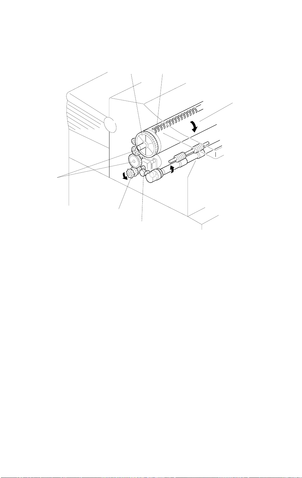
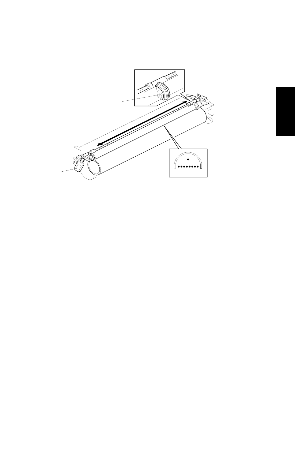
25 July 1996 CHARGE
2. CHARGE
2.1 OVERVIEW
[A]
Detailed
Descriptions
[B]
A174D501.wmf
A174D502.wmf
This model uses a single wire corona unit [A] to charge the OPC (organic
photoconductor) drum [B]. The corona unit generates a corona of negative
ions when a high negative voltage is applied to it by the charge/grid power
pack.
To make the negative corona uniform, a grid consisting of 8 wires is installed
on the charge corona unit between the corona wire and the drum. This grid
drains off any charge in excess of –860 volts, thus preventing fluctuation of
the charge potential.
2-3
CHARGE 25 July 1996
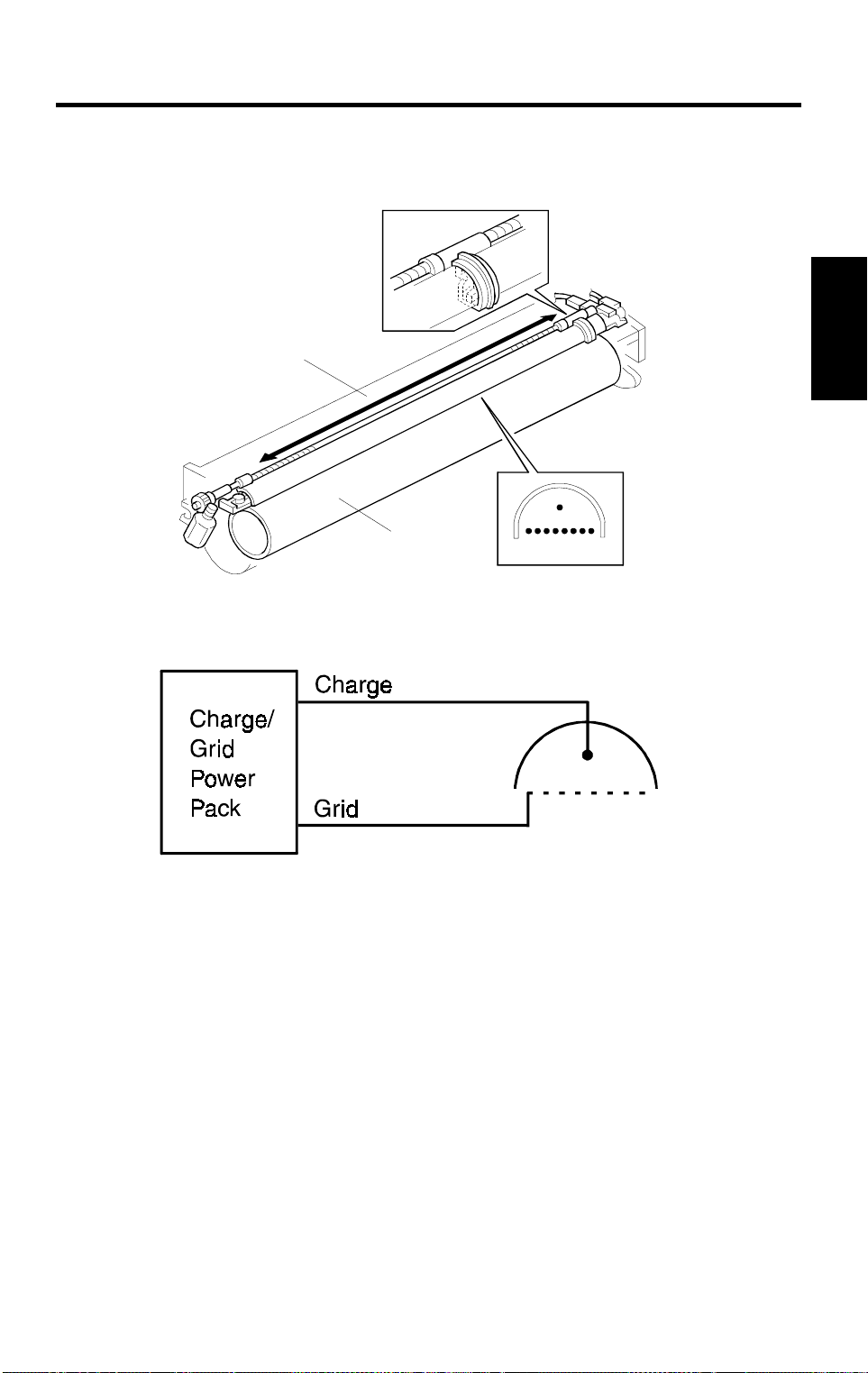
2.2 CHARGE CORONA CIRCUIT
A174D503.wmf
AA
The main board supplies +24 volts (V
) to the charge/bias/grid power pack
as the power supply source. Approximately 12 seconds after the copy
process starts, the CPU drops CN102-B7 from 5 volts to 0 volts. This
actuates the dc/dc converter within the power pack which applies a high
negative voltage of approximately –5.0 kV to the charge corona wire. The
corona wire then generates a negative corona charge.
The grid limits the maximum corona charge to –860 volts. This ensures that
the charge does not fluctuate and an even charge is applied to the drum
surface.
The copy grid voltage and charge voltage amounts can be adjusted using
SP# –14 and SP#–13 respectively.
The grid drive signal applied to CN320-4 is a pulse width modulated signal.
As the width of the pulses applied increases, the strength of the grid charge
also increases. The main board monitors the grid charge at CN102-B4 and
controls the width of the drive pulses based on this feedback.
2-4
25 July 1996 CHARGE
2.3 CHARGE WIRE CLEANING MECHANISM
[A]
[B]
A174D501-2.wmf
Detailed
Descriptions
The wire cleaner pads [A] automatically clean the wires every 297 m (500
copies/A1).
The wire cleaner is driven by a dc motor [B]. Normally the wire cleaner is
located at the front end position (home position). After 297 m (500 copies/A1)
or more copies are made and fusing temperature is less than 100°C after the
main switch is turned on, the wire cleaner motor turns on to bring the wire
cleaner to the rear end and then back to the home position.
When the wire cleaner moves from the rear to the home position, the wire
cleaner pads clean the wires.
There are no home position and return position sensors. The CPU monitors
the input voltage (5 V). When the wire cleaner reaches the end, it is stopped
and the motor is locked. At this time, input voltage slightly decreases (to
about 4 V) and the CPU judges to rotate the motor in reverse.
2-5
CHARGE 25 July 1996
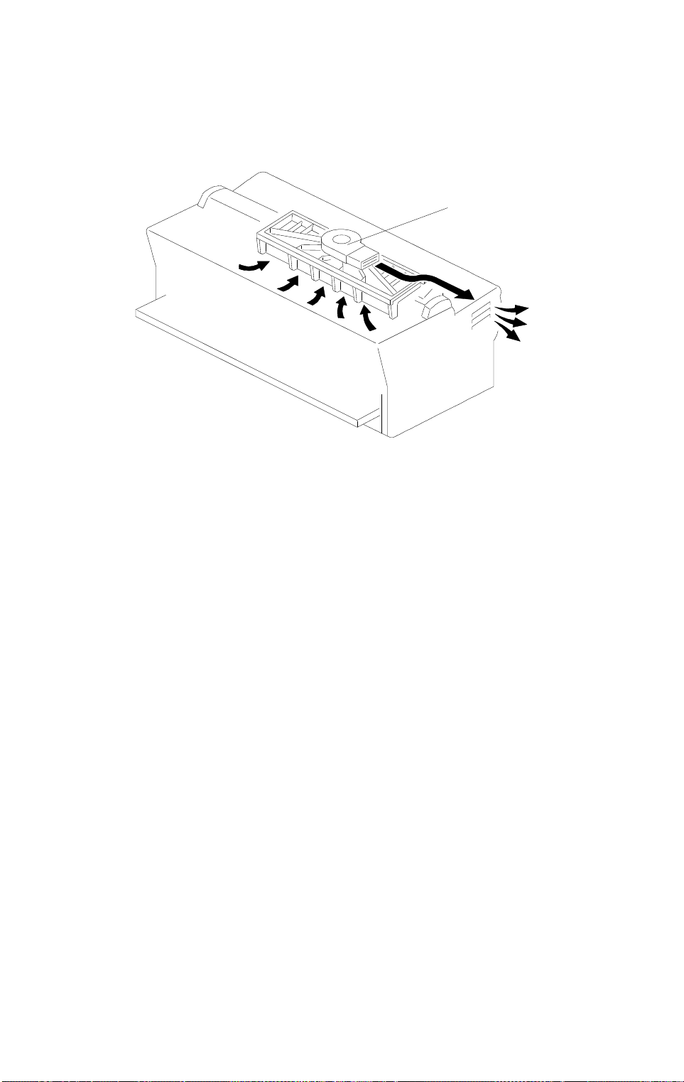
2.4 CORONA UNIT VENTILATION
[A]
A174D504.wmf
If ozone produced by the corona charge stays in the charge corona area, it
may cause uneven corona charging to the drum. To prevent this, ozone is
vacuumed out through the exhaust fan [A], and changed to oxygen by the
ozone filter before being blown out of the copier.
2-6
25 July 1996 EXPOSURE
3. EXPOSURE
3.1 OVERVIEW
[E]
[D]
[G]
[F]
[B]
[C]
Detailed
Descriptions
[A]
A174D505.wmf
Light from the exposure lamp [A] reflects off the original and through the fiber
optics [B] to the OPC drum [C]. During exposure, the original moves across
the exposure glass at the same speed as the drum’s peripheral velocity.
The platen roller [D] presses the original [E] flat against the exposure glass
[F] just above the fiber optic array. This ensures that the image is properly
focused. (The original must be within 0.2 mm of the exposure glass surface.)
The exposure lamp is a 125 V, 37 W exposure lamp.
The light sensor [G] monitors the intensity of the exposure lamp output.
2-7
EXPOSURE 25 July 1996
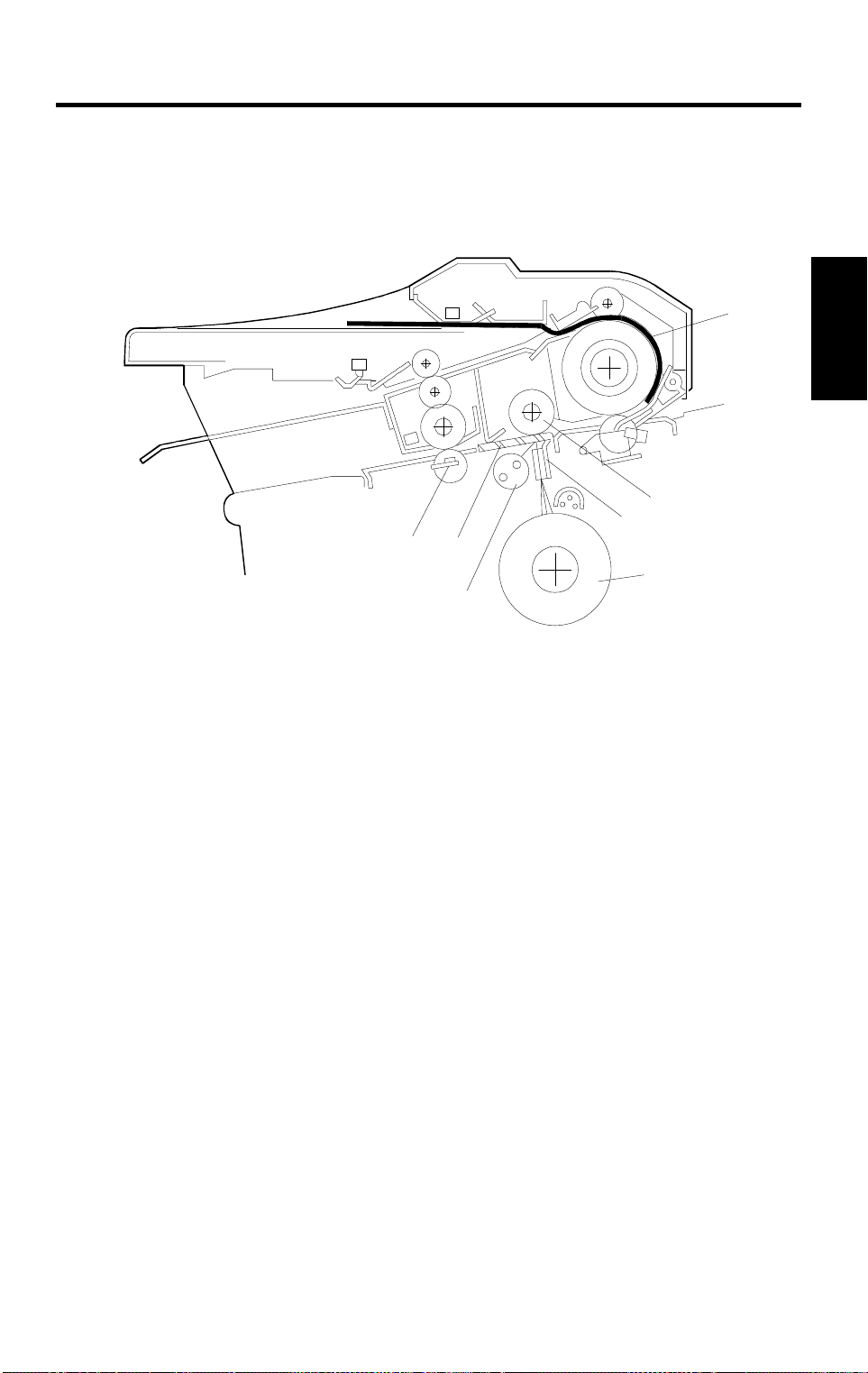
3.2 PAPER AND ORIGINAL FEED
3.2.1 Normal Original Feed
[B]
[D]
[C]
[Q]
[A]
[E]
[O]
[P]
[F]
[N]
[J]
[K]
[I]
[H]
[L]
[G]
P: Original Exit Sensor
Q: Original Switch Back Sensor
[M]
A174D506.wmf
When an original is placed on the original table, it activates the original set
sensor [A]. The main motor and development motor start rotating and the
exposure lamp turns on. 2.5 seconds later, the original feed motor starts
rotating to turning the original feed roller [B] and the original registration roller
[C]. An original feed starts. The 2.5 second delay allows time for the operator
to align the lead edge of the original against the first set of rollers to prevent
skew.
2-8

25 July 1996 EXPOSURE
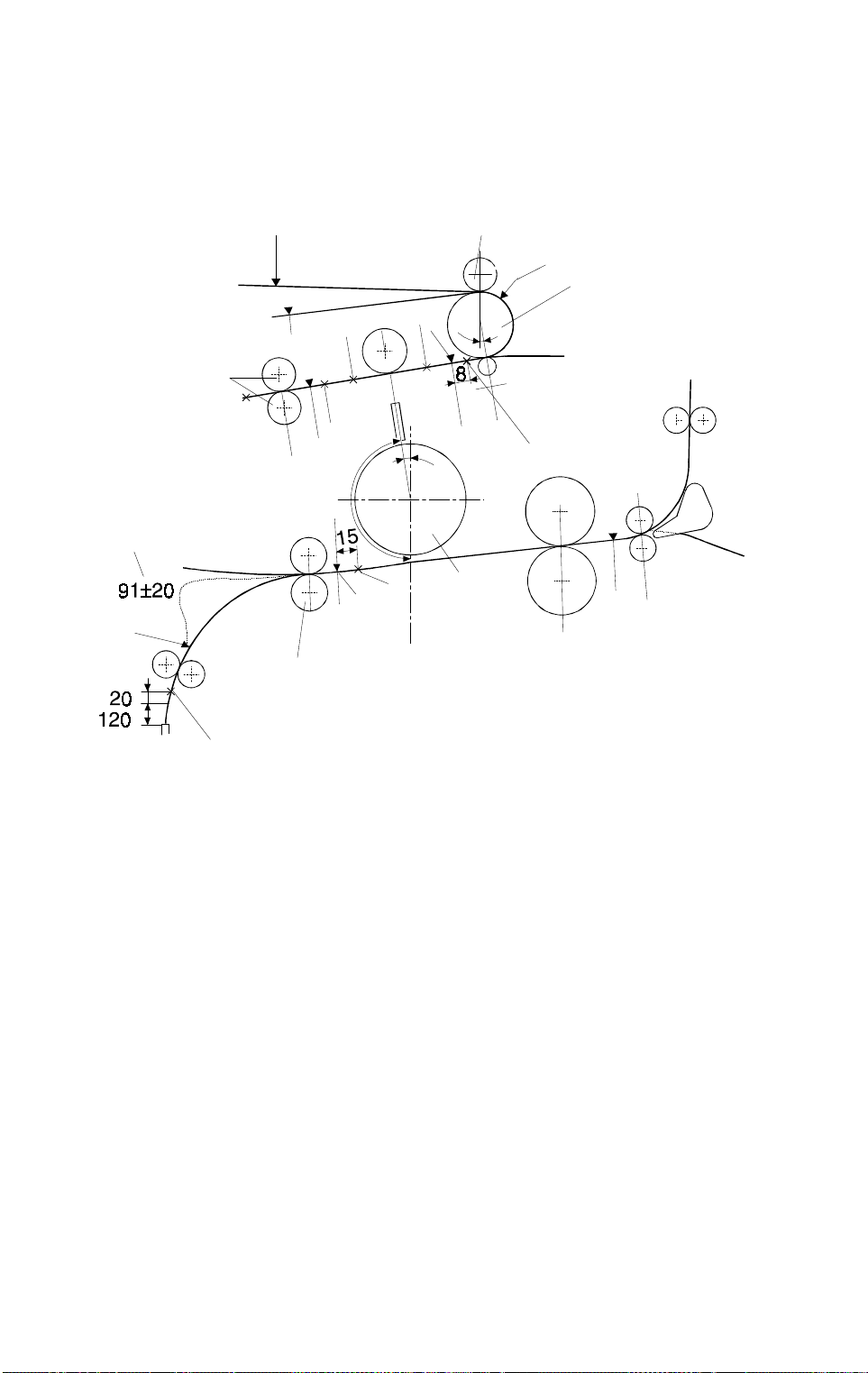
When the original lead edge sensor [D]detects the leading edge of the
original, the roll feed motor and the roll feed clutch turn on, and paper feed
starts. The original is fed to the original registration sensor [E] and stops at 33
mm [F] ahead of the original registration sensor to wait for the copy paper.
The registration clutch is activated at the appropriate time after paper feed
begins. The copy paper is fed to the registration roller [G] and the registration
clutch turns off when the copy paper reaches 15 mm [H] ahead of the
registration sensor [I]. The speed of the roll feed motor is increased from 90
mm/s to 162 mm/s to form a paper buckle [J]. Then, the speed of the roll feed
motor returns to 90 mm/s and the registration clutch turns on again. The
paper feed resumes and the copy paper is transported to the drum [K].
At the appropriate time, the original feed motor rotates again and the original
is delivered to the exposure glass.
To measure the original length for synchro-cutting, the copier CPU counts the
time after the original lead edge sensor [D] detects the leading edge of the
original until the original set sensor [A] detects the trailing edge of the
original. The copy paper length is measured by counting the number of steps
as the roll feed motor (stepper motor) turns. The roll feed motor stops at the
appropriate time and the cutter motor rotates to cut the copy paper.
Repeat copies
Detailed
Descriptions
When making repeat copies, to increase the CPM, the roll feed motor starts
rotating 0.22 s after the roll lead edge sensor [L] is de-activated and advance
the copy paper 20 mm [M] (140 mm ahead of the paper feed start position).
After the 1st copy job, at the appropriate time after the trailing edge of the
original passes the original registration sensor [E], the original feed motor
rotates reverse 3.6 times as fast as the normal speed. The original is
returned to the position [N] where the leading edge of the original is 8 mm
before the original registration sensor.
When the leading edge of the original passes the original registration sensor,
the original feed motor rotates forwards again and the original is delivered to
the exposure glass and the copy job is repeated at the trigger timing. After
all the repeat copies have been made, the original is fed out.
After original scanning, the original can be stopped and caught by the original
exit rollers [O] or it can be fed out without being caught in the original exit
rollers. This is determined by SP No.24 (Original Hold mode). If the original
hold mode is selected, the original is fed out when the Clear/Stop key is
pressed or the next original is inserted.
2-9
EXPOSURE 25 July 1996
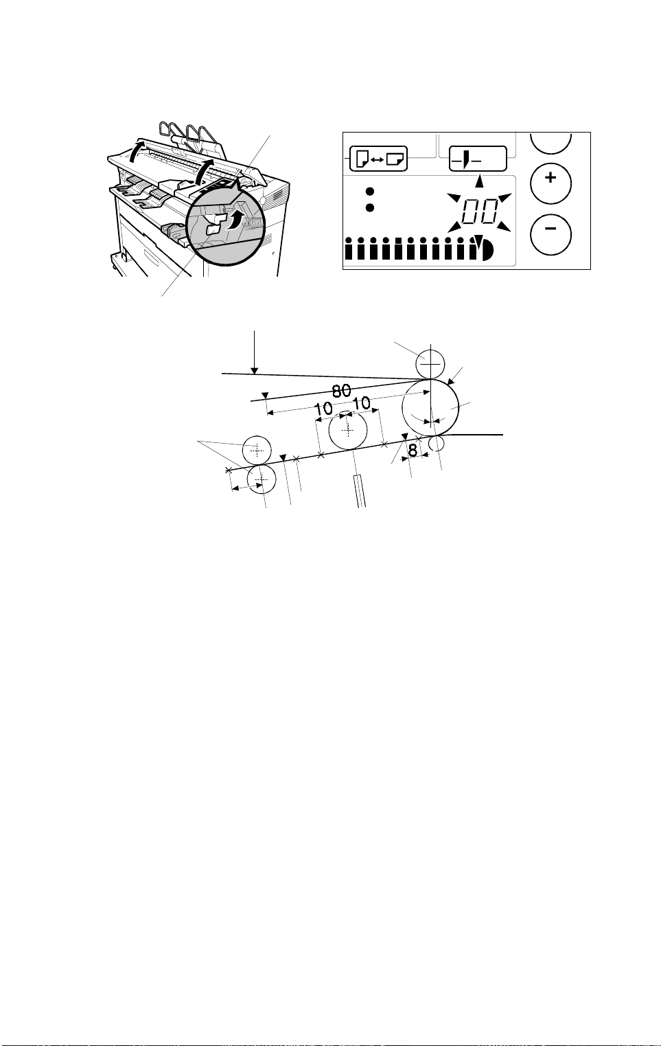
3.2.2 CHANGING MODE TO LONG NARROW ORIGINALS
[A]
A174D535.wmf
A174D536.wmf
[B]
[C]
[E]
[O]
[Q]
[P]
[D]
[F]
A174D537.wmf
If the original width is less than 515 mm (18’’) and it is longer than the
standard paper size (A0/E size), the original may be skewed by the middle
four of the 8 original feed rollers. The copy image may be warped. For such
originals, the "long narrow original" feed mode can be selected. In this mode,
the middle four original feed rollers are released while inserting the original.
When the original feed cover [A] is opened and the green lever at the right [B]
is pulled front, the middle four original feed rollers [C] are released from the
original registration roller [D]. This release condition of the middle four original
feed rollers is detected by the original mode change sensor in the rear feed
table assembly.
When the original cover is closed, "00" is blinking on the copy counter to
distinguish this mode from the normal original feed mode.
In this mode the detection of the original leading edge by the original lead
edge sensor [E] is used as a starting trigger of the main motor, development
motor, and exposure lamp. 3 seconds later, the original registration roller
delivers the original to the exposure glass. To measure the original length for
synchro-cutting, the copier CPU counts the time after the original registration
sensor [F] detects the leading edge of the original until the original lead edge
sensor detects the trailing edge of the original.
The repeat copy function cannot be used in this mode.
2-10
25 July 1996 EXPOSURE
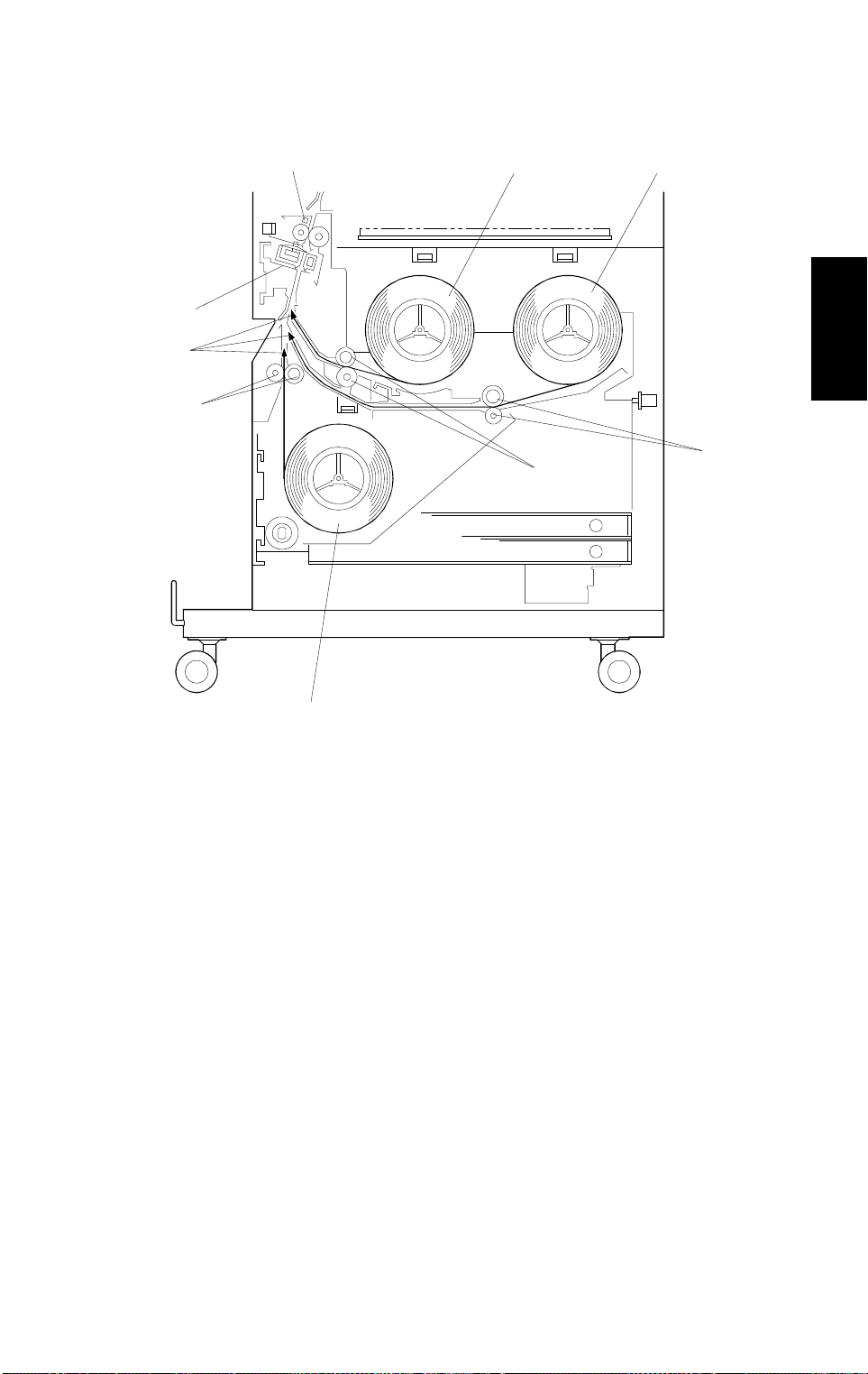
3.3 ROLL FEED
[E]
[A]
[B]
[D]
[F]
Detailed
Descriptions
[H]
[H]
[H]
[C]
A174D507.wmf
This machine has two standard roll feed units (1st [A] and 2nd [B]), one
manual feed unit, and one optional roll feed unit (3rd [C]). The cutter unit [D]
uses a sliding rotary cutting blade.
When turning on the main switch or when roll paper is replenished, the roll
feed motor rotates and the leading edge of the roll paper is fed until the roll
lead edge sensor [E] is activated. Then, the leading edge of the roll paper is
returned to the paper feed start position (120 mm before the cutter unit) [F].
2-11
EXPOSURE 25 July 1996
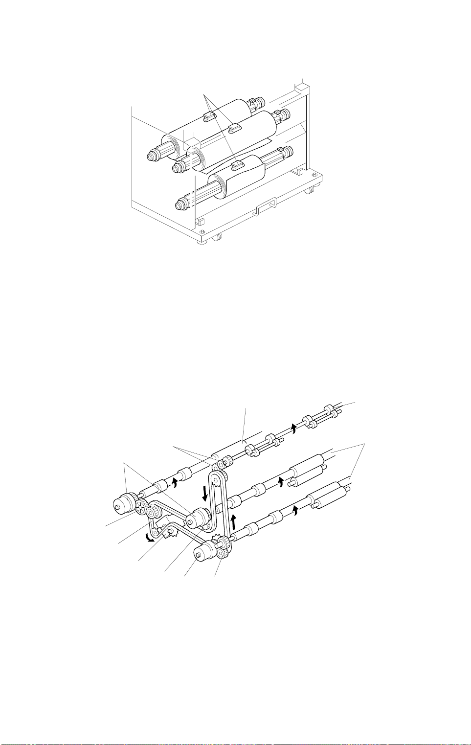
3.3.1 Roll End Detection
[A]
A174D508.wmf
The roll paper end sensor [A] is located above each roll. When the roll paper
runs out and the roll paper end sensor detects the black core of the roll, roll
end is indicated on the operation panel. If the paper is not caught by the
pull-out rollers [H] (previous page), paper feed fails. In this case, roll end is
indicated instead of a paper misfeed indication.
3.3.2 Drive Mechanism
[F]
[E]
[B]
[F]
[H]
[G]
[D]
[C]
[G]
[H]
[G]
A174D509.wmf
The roll feed roller [B] is driven by the roll feed motor [C] through the chain
[D] and gears [E]. The pull-out roller [F] of each roll feed unit is driven by the
roll feed motor through the chain and each gear [G] and each roll feed clutch
[H].
2-12
25 July 1996 EXPOSURE
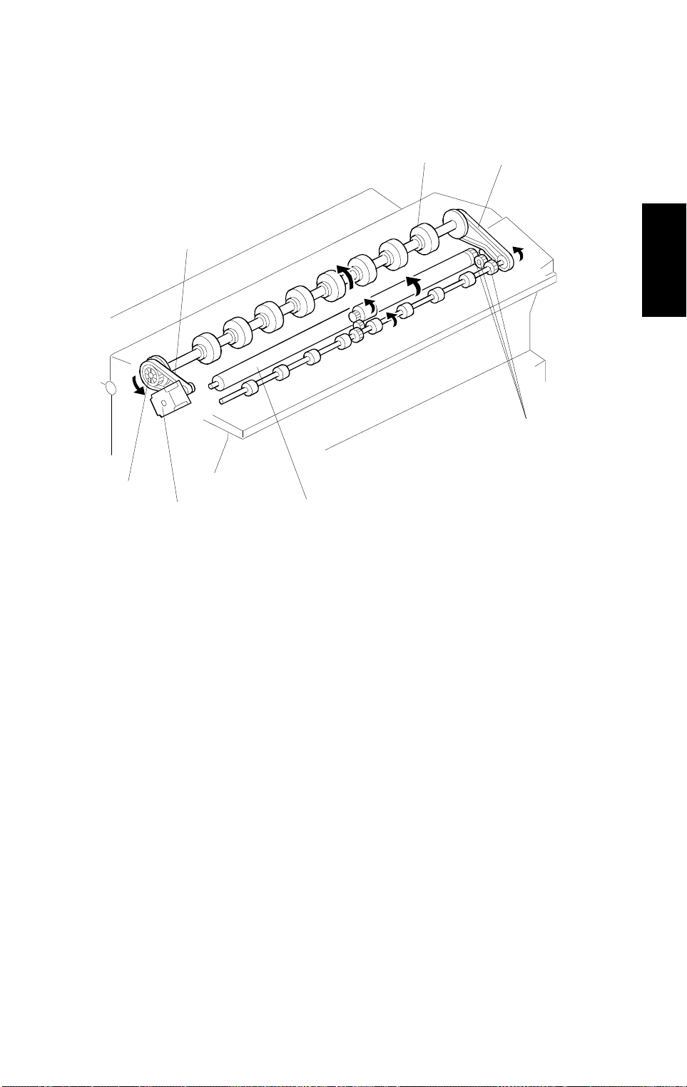
3.3.3 Drive Mechanism
[B]
[D]
[C]
[E]
[A]
[G]
Detailed
Descriptions
[F]
A174D510.wmf
The original feed roller [A] is driven through the original feed drive pulley [B]
and belt [C] by the original feed motor [D].
The platen roller [E] is rotated by the original feed motor [D] through the
gears [F] and belt [G].
2-13
EXPOSURE 25 July 1996
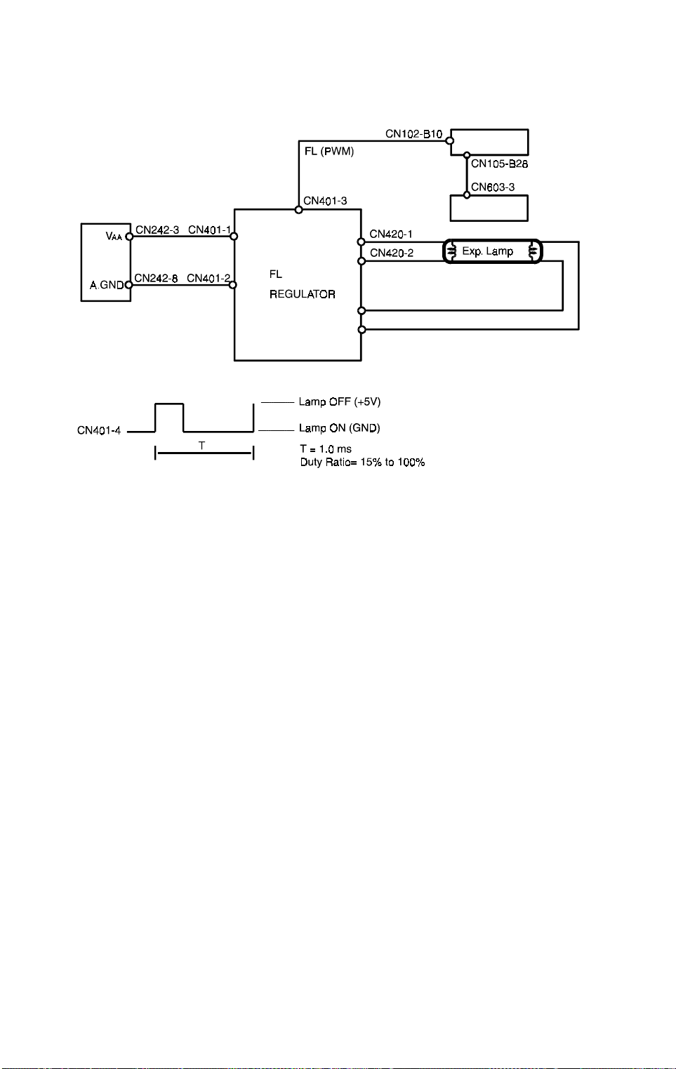
3.4 FL REGULATOR CONTROL
[D]
[C]
[A]
A174D511.wmf
The FL regulator [A] receives 24 volts dc at CN401-1 from the main board
[B]. The control signal, which is a pulse width modulated (PWM) signal, is
received at CN401-3. The PWM signal has a period (T) of 1 millisecond and
a duty ratio of 15% to 100%.
The basic light intensity level is determined either by the image density
selected at the operation panel (manual ID control) or by the original’s
background level as sensed by the ADS. The CPU uses the light sensor to
monitor the actual light intensity. The light sensor [C] directly detects the
lamp’s light output and feeds a light intensity signal back to CN105-B28 of the
main board [D]. This feedback allows the CPU to compensate for variations
in light intensity due to the lamp’s age or temperature.
2-14

25 July 1996 EXPOSURE
3.5 MANUAL ID CONTROL VS ADS
Manual ID Level
1 1.275 14 1.882
2 1.275 15 1.922
3 1.275 16 2.020
4 1.294 17 2.118
5 1.294 18 2.216
6 1.314 19 2.314
7 1.333 20 2.412
8 1.373 21 2.529
9 1.412 22 2.627
10 1.510 23 2.725
11 1.627 24 2.824
12 1.745 25 2.922
13 1.843 26 3.118
Light S e nsor
Output [V]
Manual ID Level
Light S e nsor
Output [V]
3.5.1 Manual ID Control
When in manual image density mode, the user can select one of 26 manual
ID levels. For each level, the intensity of the light output by the exposure
lamp (as measured by the light sensor) is fixed. This is shown in the above
table. The development roller bias also varies. (See the section on
development bias.)
Detailed
Descriptions
2-15
 Loading...