

Ricoh FW780 Service manual

J2SS-C3
(Machine Code: B047/B048)
Service Manual
– Insert Version –
The B047/B048 machines are based on the A163/A251/A252 copiers.
Only the differences from the base copier are described in the following pages.
Therefore, this documentation should be treated as an insert version of the base
copier’s service manual. It should always be utilized together with the base
copier’s service manual.

INSERTION PROCEDURE OF SERVICE MANUAL
1. Replace the book spine tag with the new one.
2. Insert the B047/B048 service manual a fter the A1 63/A 25 1/A252 manual.

!
IMPORTANT SAFETY NOTICES
PREVENTION OF PHYSICAL INJURY
1. Before disassembling or assembling parts of the copier and peripherals,
make sure that the copier power cord is unplugged.
2. The wall outlet should be near the copier and easily accessible.
3. Note that some components of the copier and the peripherals are supplied
with electrical voltage even if the main switch is turned off.
4. If any adjustment or operation check has to be made with exterior covers off
or open while the main switch is turned on, keep hands away from electrified
or mechanically driven components.
5. The inside and the metal parts of the fusing unit become extremely hot while
the copier is operating. Be careful to avoid touching those components with
your bare hands.
6. The copier is not attached to the table. Pushing the copier too hard may
cause it to drop onto the floor. While moving the copier, push the table.
7. When the main switch is turned on, the machine will suddenly start turning to
perform the developer initialization. Keep hands away from any mechanical
and electrical components during this period.
HEALTH SAFETY CONDITIONS
1. Never operate the copier without the ozone filters installed.
2. Always replace the ozone filters with the specified ones at the specified
intervals.
3. Toner and developer are non-toxic, but if you get either of them in your eyes
by accident, it may cause temporary eye discomfort. Try to remove with eye
drops or flush with water as first aid. If unsuccessful, get medical attention.
OBSERVANCE OF ELECTRICAL SAFETY STANDARDS
1. The copier and its peripherals must be installed and maintained by a
customer service representative who has completed the training course on
those models.

SAFETY AND ECOLOGICAL NOTES FOR DISPOSAL
1. Do not incinerate the toner cartridge or the used toner. Toner dust may ignite
suddenly when exposed to open flame.
2. Dispose of used toner, developer, and organic photoconductors according to
local regulations. (These are non-toxic supplies.)
3. Dispose of replaced parts in accordance with local regulations.

TABLE OF CONTENTS
This manual describes new items for the J2SS-C3 (B 04 7/B048).
Please refer to the J2SS Mark II (A251/A252) manual for the descriptions marked
with “*” in page column.
1. OVERALL MACHINE INFORMATION........................................ 1-1
1.1 SPECIFICATIONS.....................................................................................1-1
1.2 PAPER PATH............................................................................................1-3
1.3 DRUM PROCESSES ............................................................................... *
1.4 MECHANICAL COMPONENTS................................................................1-4
1.5 DRIVE LAYOUT....................................................................................... *
1.6 ELECTRICAL COMPONENTS..................................................................1-6
2. DETAILED SECTION DESCRIPTIONS ...................................... 2-1
2.1 DRUM....................................................................................................... *
2.1.1 DRUM CHARACTERISTICS........................................................... *
2.1.2 DRUM DRIVE.................................................................................. *
2.2 CHARGE.................................................................................................. *
2.2.1 OVERVIEW..................................................................................... *
2.2.2 CHARGE CORONA CIRCUIT......................................................... *
2.2.3 CORONA UNIT VENTILATION....................................................... *
2.3 EXPOSURE...............................................................................................2-1
2.3.1 OVERVIEW..................................................................................... *
2.3.2 PAPER AND ORIGINAL FEED (B048 ONLY)..................................2-1
Basic Operation (Manual Feed)........................................................... *
Original Jam Check Timing.................................................................. *
Drive Mechanism................................................................................. *
Original Positioning...............................................................................2-1
Scanning ...............................................................................................2-2
Start Key Enable...................................................................................2-3
2.3.3 FL REGULATOR CONTROL........................................................... *
2.3.4 MANUAL ID CONTROL................................................................... *
Manual ID Control................................................................................ *
2.4 DEVELOPMENT.......................................................................................2-4
2.4.1 OVERVIEW..................................................................................... *
2.4.2 DRIVE MECHANISM....................................................................... *
2.4.3 CROSS-MIXING.............................................................................. *
2.4.4 TONER DENSITY CONTROL..........................................................2-4
Toner Near End Condition................................................................... *
Recovery from Toner End Condition.....................................................2-5
Toner Density Sensor.......................................................................... *
2.4.5 DEVELOPMENT BIAS.................................................................... *
Basic Concept...................................................................................... *
Manual Image Density Bias................................................................. *
2.4.6 TONER SUPPLY............................................................................. *
2.5 IMAGE TRANSFER AND PAPER SEPARATION.................................... *
i

2.5.1 PRE-TRANSFER LAMP (PTL)........................................................ *
2.5.2 IMAGE TRANSFER......................................................................... *
2.5.3 PAPER SEPARATION.................................................................... *
2.5.4 PICK-OFF MECHANISM................................................................. *
2.5.5 T/S CORONA CIRCUIT ................................................................... *
2.6 CLEANING............................................................................................... *
2.6.1 OVERVIEW..................................................................................... *
2.6.2 USED TONER COLLECTION..........................................................2-6
2.7 QUENCHING............................................................................................ *
2.8 FUSING AND PAPER EXIT......................................................................2-7
2.8.1 OVERVIEW......................................................................................2-7
2.8.2 DRIVE MECHANISM....................................................................... *
Fusing Unit Drive................................................................................. *
2.8.3 TEMPERATURE CONTROL............................................................2-8
Fusing Circuit Operation...................................................................... *
Overheat Protection............................................................................. *
Hot Roller Temperature Control............................................................2-8
2.8.4 TEMPERATURE CONTROL........................................................... *
The Ready Condition........................................................................... *
Fusing Unit Operating Modes.............................................................. *
2.8.5 ENERGY SAVER FUNCTION......................................................... *
2.8.6 FUSING ENTRANCE GUIDE HEIGHT............................................ *
2.9 OTHERS .................................................................................................. *
2.9.1 ROLL CUTTING RAIL ..................................................................... *
2.10 ENERGY STAR COMPLIANT MACHINES
(ALL THE DESTINATION)......................................................................2-9
3. INSTALLATION ........................................................................... 3-1
3.1 INSTALLATION REQUIREMENTS...........................................................3-1
3.1.1 ENVIRONMENT...............................................................................3-1
3.1.2 MINIMUM SPACE REQUIREMENTS...............................................3-2
3.1.3 MACHINE LEVEL.............................................................................3-2
3.1.4 POWER SOURCE............................................................................3-3
3.2 INSTALLATION PROCEDURE.................................................................3-4
3.2.1 COPIER............................................................................................3-4
Accessory Check.................................................................................. 3-4
B048 copier only (step 21)..................................................................3-12
B047 copier only (step 22 and 23)......................................................3-12
Both copiers (step 24 and 25).............................................................3-12
3.2.2 TABLE (B439) ................................................................................3-13
Accessory Check................................................................................ 3-13
3.2.3 COPY tray (B440)........................................................................... 3-15
Accessory Check................................................................................ 3-15
3.2.4 ROLL FEEDER1 and 2 (B435/b436)..............................................3-19
Accessory Check................................................................................ 3-19
3.2.5 Roll Cutting Rail (B437)..................................................................3-28
ii

4. SERVICE TABLES...................................................................... 4-1
4.1 PREVENTIVE MAINTENANCE SCHEDULE........................................... *
4.1.1 PM TABLE....................................................................................... *
4.1.2 REGULAR PM PROCEDURE......................................................... *
4.2 SERVICE TABLES................................................................................... *
4.2.1 TEST POINTS................................................................................. *
Main Board .......................................................................................... *
Charge/Bias/Grid Power Pack............................................................. *
4.2.2 VARIABLE RESISTORS................................................................. *
Charge/Bias/Grid Power Pack............................................................. *
T&S Power Pack.................................................................................. *
4.3 SERVICE TOOLS......................................................................................4-1
4.3.1 SERVICE PROGRAM MODE...........................................................4-1
Service Program Mode Access Procedure.......................................... *
Service Program Mode Table...............................................................4-1
4.3.2 INPUT/OUTPUT CHECK MODE....................................................4-23
Input/Output Check Mode Access Procedure...................................... *
Input Check Mode Table.....................................................................4-23
Output Check Mode Table..................................................................4-23
4.3.3 POWER ON INITIAL SETTING MODE........................................... *
4.4 JAM CODE LIST.....................................................................................4-25
4.4.1 ACCESS PROCEDURE.................................................................. *
4.4.2 JAM CODE TABLE.........................................................................4-25
Fixed Paper Size Pattern Data (SP No. 22)........................................4-27
Default Settings for Each Destination (SP#-1)....................................4-28
4.5 SPECIAL TOOLS AND LUBRICANTS..................................................... *
4.6 SERVICE REMARKS..............................................................................4-29
4.6.1 DRUM UNIT .................................................................................... *
Drum.................................................................................................... *
4.6.2 CHARGE CORONA......................................................................... *
4.6.3 OPTICS........................................................................................... *
4.6.4 DEVELOPMENT ............................................................................. *
4.6.5 TRANSFER AND SEPARATION..................................................... *
4.6.6 CLEANING UNIT............................................................................. *
4.6.7 FUSING UNIT.................................................................................. *
4.6.8 ORIGINAL FEED............................................................................. *
4.6.9 PAPER FEED.................................................................................. *
4.6.10 ROLL FEEDER.............................................................................. *
4.6.11 OTHERS........................................................................................ *
4.6.12 AC DRIVE BOARD.......................................................................4-29
Service Remark for 220 ~ 240 V Version............................................4-29
Service Remarks for 120 V Version....................................................4-30
5. REPLACEMENT AND ADJUSTMENT........................................ 5-1
5.1 EXTERIOR COVERS............................................................................... *
5.1.1 LEFT SIDE COVER REMOVAL...................................................... *
Left Upper Cover ................................................................................. *
Left Lower Cover.................................................................................. *
iii

5.1.2 RIGHT SIDE COVER REMOVAL .................................................... *
Right Upper Cover............................................................................... *
Right Lower Front, Right Lower Middle, and Right Lower
Rear Covers......................................................................................... *
5.1.3 REAR COVER REMOVAL .............................................................. *
Rear Cover .......................................................................................... *
5.2 OPTICS.................................................................................................... *
5.2.1 ORIGINAL FEED UNIT REMOVAL (A252 ONLY)........................... *
5.2.2 EXPOSURE GLASS REMOVAL (A252 ONLY)............................... *
5.2.3 EXPOSURE LAMP REMOVAL (A252 ONLY)................................. *
5.2.4 FIBER OPTICS ARRAY REMOVAL (A252 ONLY).......................... *
5.2.5 LIGHT SENSOR REPLACEMENT (A252 ONLY)............................ *
5.2.6 SYNCHRO-CUT LENGTH ADJUSTMENT (A252 ONLY)............... *
5.3 DEVELOPMENT...................................................................................... *
5.3.1 DEVELOPMENT UNIT REMOVAL.................................................. *
5.3.2 DEVELOPER REMOVAL................................................................ *
5.3.3 TONER DENSITY SENSOR REPLACEMENT................................ *
5.3.4 PTL REPLACEMENT...................................................................... *
5.3.5 DEVELOPMENT BIAS VOLTAGE ADJUSTMENT ......................... *
Bias Voltage for Image Area................................................................ *
Bias Voltage for Non-image Area ........................................................ *
5.4 DRUM UNIT ..............................................................................................5-1
5.4.1 DRUM UNIT REMOVAL................................................................. *
5.4.2 DRUM REPLACEMENT...................................................................5-1
5.4.3 CLEANING BLADE REPLACEMENT.............................................. *
5.4.4 CHARGE CORONA UNIT REMOVAL............................................. *
5.4.5 CHARGE CORONA WIRE REPLACEMENT .................................. *
5.4.6 PICK-OFF PAWL UNIT REMOVAL................................................. *
5.4.7 GRID VOLTAGE ADJUSTMENT..................................................... *
5.4.8 DRUM CURRENT ADJUSTMENT .................................................. *
Charge Current Adjustment................................................................. *
Transfer Current Adjustment................................................................ *
Separation Current Adjustment............................................................ *
5.5 FUSING.....................................................................................................5-2
5.5.1 FUSING UNIT REMOVAL............................................................... *
5.5.2 HOT ROLLER REPLACEMENT...................................................... *
5.5.3 PRESSURE ROLLER REPLACEMENT.......................................... *
5.5.4 PRESSURE ROLLER THERMISTOR REPLACEMENT................. *
5.5.5 PRESSURE ROLLER STRIPPER UNIT REPLACEMENT.............. *
5.5.6 HOT ROLLER STRIPPER UNIT REPLACEMENT.......................... *
5.5.7 HOT ROLLER THERMISTOR REPLACEMENT ..............................5-2
5.5.8 FUSING THERMOFUSE REPLACEMENT......................................5-2
5.5.9 FUSING TEMPERATURE ADJUSTMENT.......................................5-3
5.6 T & S CORONA UNIT .............................................................................. *
5.6.1 T & S CORONA UNIT REMOVAL................................................... *
5.6.2 TRANSFER AND SEPARATION CORONA WIRE
REPLACEMENT.............................................................................. *
Preparation.......................................................................................... *
Separation Corona Wire Replacement................................................ *
iv

Transfer Corona Wire Replacement .................................................... *
5.7 OTHERS .................................................................................................. *
5.7.1 OZONE FILTER REPLACEMENT................................................... *
5.7.2 ANTICONDENSATION HEATER INSTALLATION.......................... *
5.8 COPY QUALITY ADJUSTMENT...............................................................5-4
5.8.1 LIGHT SENSOR ADJUSTMENT..................................................... *
5.8.2 IMAGE BIAS ADJUSTMENT........................................................... *
5.8.3 TONER DENSITY ADJUSTMENT................................................... *
5.8.4 REGISTRATION ADJUSTMENT......................................................5-4
6. TROUBLESHOOTING ................................................................ 6-1
6.1 COPY QUALITY TROUBLESHOOTING.................................................. *
6.1.1 LOW IMAGE DENSITY................................................................... *
6.1.2 UNEVEN COPY IMAGE.................................................................. *
6.1.3 DIRTY BACKGROUND................................................................... *
6.1.4 BLACK LINE OR BAND................................................................... *
6.1.5 ENTIRELY BLANK COPY............................................................... *
6.1.6 PAPER CREASING......................................................................... *
6.2 SERVICE CALL CONDITIONS................................................................. 6-1
6.2.1 SC CODE DESCRIPTIONS .............................................................6-1
SC Code E-1: Exposure Lamp Abnormal.............................................6-1
SC Code E-2: Fusing Thermofuse Open..............................................6-1
SC Code E-3: Hot Roller Thermistor Open...........................................6-1
SC Code E-4: Hot Roller Thermistor Short...........................................6-2
SC Code E-5: Pressure Roller Thermistor Open..................................6-2
SC Code E-6: Pressure Roller Thermistor Short..................................6-2
SC Code E-7: Fusing Overheat............................................................6-2
SC Code E-8: Fusing Warm-up Error...................................................6-3
SC Code E-9: Toner Density Sensor Abnormal....................................6-3
SC Code E-10: Main Motor Abnormal...................................................6-3
SC Code E-11: Toner Density Sensor Adjustment Error......................6-3
SC Code E-13: Total Counter Abnormal...............................................6-4
SC Code E-14: Zero Cross Signal Detection Abnormal........................6-4
SC Code E-15: Main Switch Abnormal................................................. 6-4
SC Code E-17: Unstable Fusing Temperature .....................................6-4
SC Code E-18: Fusing Lamp Continuous Light....................................6-4
6.3 BLOWN FUSE TABLE ..............................................................................6-5
6.3.1 POWER SUPPLY UNIT....................................................................6-5
Europe Version.....................................................................................6-5
U.S.A. Version......................................................................................6-5
AC Drive Board.....................................................................................6-5
ROLL FEEDER UNIT (B435/B436)
1. OVERALL MACHINE INFORMATION.................................B436-1
1.1 SPECIFICATIONS.............................................................................. B436-1
1.2 ELECTRICAL COMPONENT DESCRIPTIONS................................. B436-2
v

2. DETAILED SECTION DESCRIPTIONS ................................B436-3
2.1 MECHANICAL OPERATION.............................................................. B436-3
2.1.1 BASIC OPERATION.................................................................. B436-3
2.1.2 ROLL EDITION DETECTION.................................................... B436-5
2.1.3 DRIVE MECHANISM................................................................. B436-5
2.1.4 CUTTER OPERATION.............................................................. B436-6
3. REPLACEMENT A ND ADJUSTMENT..................................B436-7
3.1 CUTTER UNIT REPLACEMENT........................................................ B436-7
3.2 ROLL FEED LEADING EDGE SENSOR REPLACEMENT................ B436-8
3.3 ROLL FEED UNIT REMOVAL............................................................ B436-9
3.4 ROLL FEED CLUTCH REPLACEMENT.......................................... B436-10
3.5 ROLL FEED MOTOR REPLACEMENT ........................................... B436-11
3.6 ROLL END SENSOR REPLACEMENT............................................ B436-12
3.7 CUT LENGTH ADJUSTMENT.......................................................... B436-13
Preset Cut : Adjustment standards: ±3 mm (for Length Shorter
than 420 mm) ±5 mm (for 420 to 1,189 mm) ±11 mm
(3,000 mm) .................................................................................. B436-13
3.8 SIDE REGISTRATION ADJUSTMENT ............................................. B436-14
vi

11 May, 2001 SPECIFICATIONS
1. OVERALL MACHINE INFORMATION
1.1 SPECIFICATIONS
Configuration: Table top
Copy Process: Electrostatic transfer system
Original Feed: Sheet feed
Original Size: Maximum: 914 x 3,000 (36" x 118")mm
Minimum: A4 (8
Copy Size: Same as “Original Size”
Copying Speed: 4 cpm (A1/D sideways)
First Copy: 21 seconds (A1/D sideways): B047 copier
25 seconds (A1/D sideways): B048 copier
Warm-up Time:
Multi-Copy: B047: Single copies only,
Automatic Reset: 2 minutes after copying has finished (can be set to
Photoconductor: Organic photoconductor drum
Within 3 minutes (Room temperature 23°C)
B048: Up to 10 copies
1, 3, 4, or 5 minutes or to no auto reset)
" x 11") lengthwise
1/2
Overall
Information
Drum Charge: Scorotron corona wire and grid (Negative Charge)
Reproduction Ratio:
Exposure System: Slit exposure via fiber optic array
Exposure Lamp: Fluorescent lamp (26 W)
Development: Dual-component dry toner system
Toner Replenishment: Cartridge system (750 g toner/cartridge)
Toner Consumption: 1,860 A1 or D copies per cartridge (6% original)
Development Bias: Negative
Toner Density Control: Direct toner density detection using an induction
Image Density Adjustment: Development bias control + exposure control
Paper Separation: Dual wire AC corona and pick-off pawls
Cleaning: Cleaning blade
Paper Feeding: Manual feed (roll feeder optional)
Image Fusing: Teflon heat roller (upper) and a silicone rubber
1 : 1 (±0.5%)
sensor
pressure roller (lower)
Fusing Lamp: Halogen lamp
(115 V: 1,200 W, 230 V: 1,200 W)
1-1

SPECIFICATIONS 11 May, 2001
Self-diagnostic Codes: 16 codes, displayed on the copy counter
Power Source: 115 V/60 Hz, 12 A
220 ~ 240V/50, 60 Hz, 7A
Power Consumption: Maximum: 1.4 kW
Warm-up: 1.3 kW
Ready: 0.04 to 1.3 kW
Copy cycle:1.4 kW
Dimensions (W x D x H): B047: 1,080 x 570 x 490 mm
42.5" x 22.4" x 19.3"
B048: 1,080 x 623 x 480 mm
42.5" x 24.5" x 18.9"
Weight: B047: 79 kg, 174.0 lbs
B048: 80 kg, 176.0 lbs
Optional Equipment and Machine Configuration
Configuration
Main frame Optional equipment
Roll feeder (B435: 1 roll, B436: 2 rolls) —
B047 copier
B048 copier
Roll cutting rail (B437) —
Table (B439) —
Side guides (B438) —
Roll feeder (B435: 1 roll, B436: 2 rolls) Copy tray (B440)
Side guide (B438) —
Additional equipment
NOTE: 1) Roll cutting rail cannot be installed on the B048 copier.
2) Key counters cannot be installed on these copiers.
3) The B048 requires a roll feeder (either 1 roll or 2 rolls). While the roll
feeders are shipped separately, they are not really optional. One must
be installed for the B048 to function properly. .
Other Optional Equipment
• Roll Holder Unit (B394)
• Drum anti-condensation heater
Specifications are subject to change without notice.
1-2
11 May, 2001 PAPER PATH
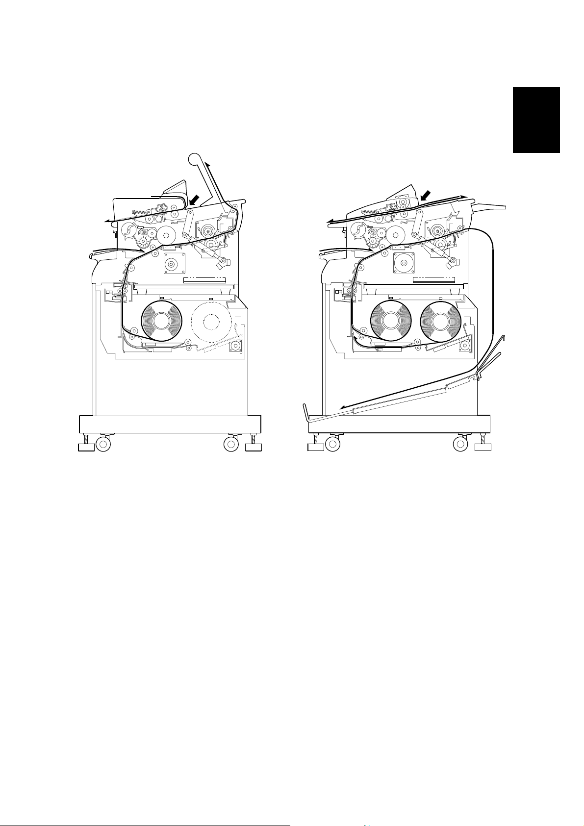
1.2 PAPER PATH
- B047 copier -
- B048 copier -
Overall
Information
A
B
C
B047V102.WMF
E
D
E
A
B
D
C
B048V102.WMF
A: Original Path
B: Manual Feed Path
C: Roll Feeder Path
D: Paper Exit
E: Original Path: Rear Feeder
There are two versions of this machine. The B047 is the basic version. It can only
make one copy at a time. The B048 is the multi-print version. It can make multiple
copies of an original (scanning and copying an original multiple times).
Both versions can be equipped with either a single or a double paper roll.
1-3
MECHANICAL COMPONENTS 11 May, 2001
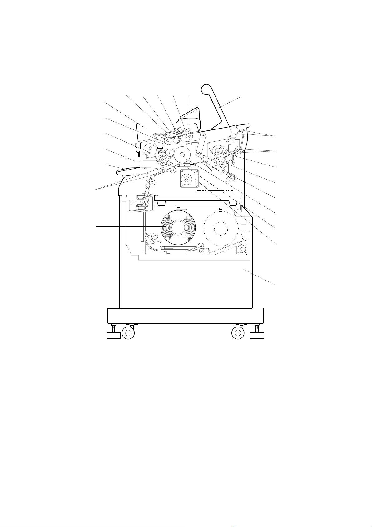
1.4 MECHANICAL COMPONENTS
14
13
19
18
17
16
15
20 21 22 1 2
3
4
5
6
7
8
9
10
11
1. 1st Original Feed Roller
2. 1st Press Rollers
3. Copy Tray
4. Exit Rollers
5. Fusing Exit Rollers
6. Hot Roller
7. Pressure Roller
8. Gas Spring
9. OPC Drum
10. T/S Corona Unit
11. Main Drive Unit
12
B047V101.WMF
12. Roll Feed Unit (1 roll or 2 rolls)
13. Roll Paper
14. Paper Registration Rollers
15. Manual Feed Table
16. Development Unit
17. Toner Cartridge
18. 2nd Original Feed Roller
19. Original Table
20. 2nd Original Press Roller
21. Exposure Lamp
22. Fiber Optic Array
1-4
11 May, 2001 MECHANICAL COMPONENTS
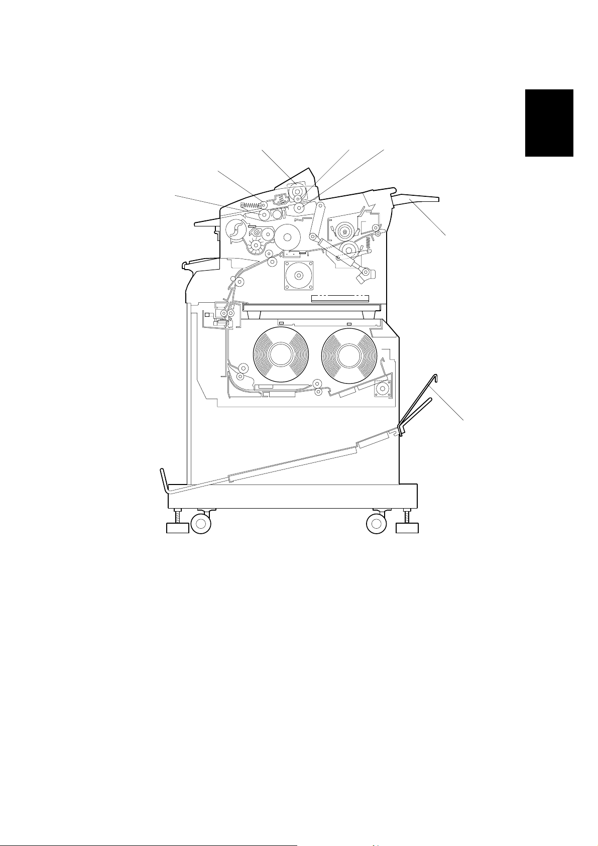
27
28 29
26
25
23
Overall
Information
23. Original Guide
24. Optional Copy Tray
25. Original Entrance Roller
26. Original Entrance Press Roller
24
B048V101.WMF
27. Original Roller Feed Motor
28. Original Rear Press Roller
29. Original Rear Roller
1-5

ELECTRICAL COMPONENTS 11 May, 2001
1.6 ELECTRICAL COMPONENTS
Refer to the electrical component layout on the reverse side of the Point to Point
index (Water proof paper).
Name Function Index. No.
Motors
Main Drives all mechanical components except the fans
(DC Motor).
Exhaust Fan Removes the ozone built up around the drum
section to the ozone filter (DC Motor).
Original Feed
(B048 only)
Magnetic Clutches
Registration Drives the registration rollers. 30
Toner Supply Turns on to supply toner to the development unit. 31
Solenoids
Pick-off Pawl Moves the pick-off pawls against the drum. 6
Drives the original feed motor (DC Motor).
32
5
45
Switches
Main Supplies power to the copier. 17
Original & Paper
Feed Safety
Fusing Exit Safety Cuts AC power when the fusing exit unit is opened. 12
Used Toner Cover “Door Open” is displayed on the operation panel
Sensors
Door Open Indicates “Door Open” on the operation panel and
Toner Density Detects the density of toner in the developer. 26
Original Registration Activates when the leading edge of the original
Light Measures the intensity of the exposure lamp’s
Entrance Feed Activates when copy paper is inserted (jam
Registration
Exit Detects jams through the fusing exit unit. 7
Original Entrance
(B048 only)
Original Rear
(B048 only)
Exit Cover Open Indicates “Door Open” in the operation panel and
Toner Overflow Detects whether the used toner tank is full or not. 46
Cuts AC power when the original or paper feed unit
are opened.
when the used toner cover is open.
prevents operation.
passes the front of the exposure glass.
output.
detector).
Activates when copy paper arrives at the
registration rollers (jam detector).
Measures the original length and detects jams. 43
Detects original jams. 44
prevents operation.
18
48
29
4
27
24
25
47
1-6

11 May, 2001 ELECTRICAL COMPONENTS
Name Function Index. No.
Printed Circuit Boards
Main Controls all copier functions both directly and
through other PCBs.
22
PSU Converts t h e voltag e from AC to DC voltage. 21
AC Drive Provides AC power to the fusing lamp and PSU. 15
FL Regulator Stabilizes power to the exposure lamp. 23
Operation Panel Controls the operation panel display. 10
Lamps
Exposure Provides light to reflect the original’s image onto
the drum (fluorescent lamp).
2
Fusing Provides heat to the fusing unit. 3
Pre-Transfer (PTL) Reduces the charge on the drum surface prior to
image transfer.
Quenching (QL) Neutralizes any charge remaining on the drum
surface after cleaning.
20
1
Power Packs
Charge/Bias/
Grid Power Pack
Transfer/Separation Provides high voltage power for the transfer corona
Provides high voltage power for the charge corona,
charge grid, and development bias.
and separation.
19
16
Overall
Information
Thermistors
Hot Roller Monitors the hot roller’s surface temperature. 8
Pressure Roller Monitors the pressure roller’s surface temperature. 11
Thermofuses
Fusing Protects the fusing unit against overheating. 9
Heaters
Anti-condensation Keeps m oistur e from forming inside the copier
(option).
13
Others
Total Counter Keeps track of the total length of copies made
(Europe) or the total copies made (U.S.A.).
Circuit Breaker
Guards against voltage surges in the input power.
(Europe, Asia)/
28
14
Fuse (U.S.A.)
1-7
11 May, 2001 EXPOSURE
2. DETAILED SECTION DESCRIPTIONS
2.3 EXPOSURE
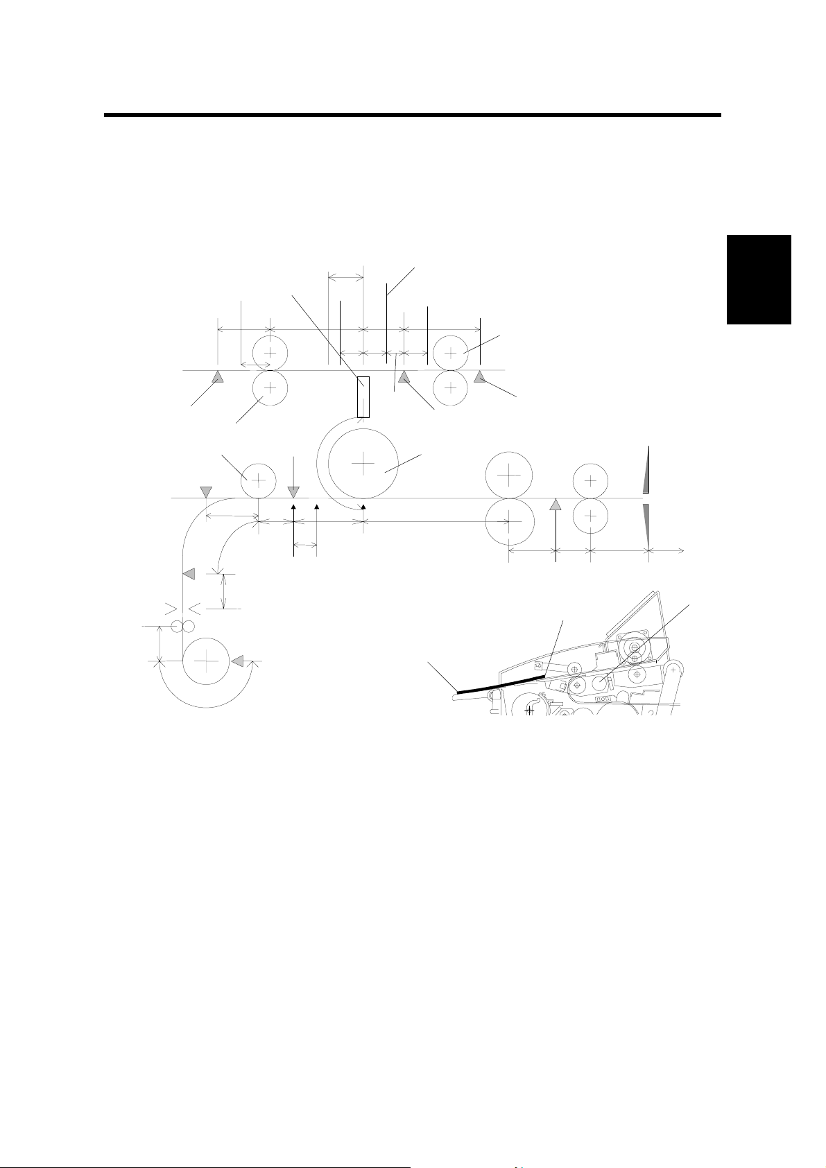
2.3.2 PAPER AND ORIGINAL FEED (B048 ONLY)
[E]
[C]
[G]
[D]
[L]
26 mm
[F]
[H]
10 mm
[I]
J: Original Rear Roller
K: Original Rear Sensor
L: Fiber Optics Array
[B]
[J]
[K]
[A]
Detailed
Descriptions
[M]
B047D500.WMF
B047D501.WMF
NOTE: For clarity’s sake, the following description will ref er to the paper’s edges
as edge [A] (furthest edge from the operator) and edge [B] (closest to the
operator).
Original Positioning
In the B048 copier, edge [A] of the original is placed onto the original table. This
activates the original entrance sensor [C].
The main motor turns the original entrance rollers [D]. The quenching lamp,
development bias and PTL also turn on.
For proper feeding (especially for a thin original), the original entrance rollers rotate
backwards (feeding towards the operator) for 300 ms. This ensures that the original
is gripped firmly by both of the original entrance rollers [D], feeding it evenly.
2-1

EXPOSURE 11 May, 2001
4 seconds after the sensor is activated, the original feed motor starts rotating. This
delay gives the user time to align edge [A] against the original entrance rollers [D].
This helps prevent skew.
The original is fed through the machine to the scanning start position [E]. This
machine scans the original backwards, starting with edge [B] and scanning towards
edge [A]. The original is now ready to scan.
Scanning
The original is scanned, moving back towards the operator.
When edge [ A] activates the original registration sensor [F], the roll paper feed
motor turns on. Copy paper begins to feed, and the registration clutch is activated.
When edge [B] reaches the original feed start posi tion [E] (26 mm ahead of the
original registration sensor [F]), the original feed motor stops to wait for the copy
paper.
In the copy section, the registration clutch turns off once the copy paper’s leading
edge is 10 mm past the registration sensor [H]. The voltage is now applied to the
charge coro na.
The original feed motor begins rotating towards the operator again at 60 mm/s, and
the original is delivered to the exposure glass. Light from the exposure lamp [M] is
reflected off the paper to the fiber optics array [L].
Once the original’s edge [B] passes the original entrance sensor, the registration
clutch and roll paper feed motor turn on agai n. The pap er feed res ume s and the
copy paper is transported to the drum [I].
To measure the original length for cutting, the copier’s CPU measures the time
from when the original registration sensor detects edge [A] until the original
entrance sensor detects edge [B].
The copy paper length is measured by counting the number of steps as the roll
paper feed motor (a stepper motor) turns. Just before the paper is cut, the feed
motor speed doubles. This creates a buckle at the trailing edge of the copy paper.
The feed motor then stops as the cutter unit cuts the paper. Copying, however,
continues. The buckle provides the necessary slack while cutting.
When making duplicate copies, the original feed motor pauses, then changes
directions again, and the original is fed back to the scanning position 200 mm/s.
Once previous paper exits out of the roll feeder, the roll paper feed starts as well,
and the process repeats.
After all copies are made, the original is delivered to the original table. If original
hold mode is enabled (SP16), the original will stop with edge [A] caught by the
original entrance rollers. The original can be fed out by pressing the ! key. If
original hold mode is not enabled, the original feeds out completely, and is not
caught.
2-2

11 May, 2001 EXPOSURE
Start Key Enable
When the start key enabled (SP34) is set, the start key acts as a starting trigger. In
this mode, when the original activates the original registration sensor, edge [B] is
delivered to the original registration sensor position. Everything pauses until the
user presses the start key. Original feed and paper feed then resume.
Detailed
Descriptions
2-3

DEVELOPMENT 11 May, 2001
2.4 DEVELOPMENT
2.4.4 TONER DENSITY CONTROL
The toner supply amount ratio is determined by the following conditions.
N
L
H
TS
Level
0
1
2
3
4
5
0
1
2
3
4
5
0
1
2
3
4
5
201 ~ 250
sheets
(120 ~ 150 m)
<
2.25 ≤ V
2.70
<
2.70 ≤ V
3.15
<
3.15 ≤ V
3.60
<
3.60 ≤ V
3.90
3.90 ≤ V
<
3.25 ≤ V
3.50
<
3.50 ≤ V
3.80
<
3.80 ≤ V
4.00
<
4.00 ≤ V
4.35
4.35 ≤ V
<
2.00 ≤ V
2.40
<
2.40 ≤ V
2.80
<
2.80 ≤ V
3.20
<
3.20 ≤ V
3.60
3.60 ≤ V
TS
TS
TS
TS
TS
TS
TS
TS
TS
TS
TS
TS
<
<
<
<
TS
<
<
<
<
TS
<
<
<
<
TS
(30 ~ 60 m)
<
3.50 ≤ V
<
3.80 ≤ V
<
4.10 ≤ V
<
4.20 ≤ V
<
4.30 ≤ V
<
4.33 ≤ V
<
4.36 ≤ V
<
4.40 ≤ V
<
3.00 ≤ V
<
3.50 ≤ V
<
4.00 ≤ V
<
4.20 ≤ V
51 ~ 100
sheets
3.80
4.10
4.20
4.35
4.35 ≤ V
4.33
4.36
4.40
4.43
4.43 ≤ V
3.50
4.00
4.20
4.30
4.30 ≤ V
TS
TS
TS
TS
TS
TS
TS
TS
TS
TS
TS
TS
TS
TS
TS
0 ~ 50 sheets
(~ 30 m)
TS
V
< 4.00 VTS < 3.50 VTS < 3.00 VTS < 2.50 VTS < 2.25 VTS < 2.00
4.00 ≤ V
TS
4.10
4.10 ≤ V
TS
4.20
4.20 ≤ V
TS
4.30
4.30 ≤ V
TS
4.40
4.40 ≤ V
TS
V
4.35 ≤ V
TS
< 4.35 VTS < 4.30 VTS < 4.25 VTS < 3.75 VTS < 3.25 VTS < 2.75
TS
4.38
4.38 ≤ V
TS
4.40
4.40 ≤ V
TS
4.42
4.42 ≤ V
TS
4.45
4.45 ≤ V
TS
V
4.00 ≤ V
TS
< 4.00 VTS < 3.00 VTS < 2.50 VTS < 2.25 VTS < 2.00 VTS < 1.80
TS
4.10
4.10 ≤ V
TS
4.20
4.20 ≤ V
TS
4.30
4.30 ≤ V
TS
4.40
4.40 ≤ V
TS
(60 ~ 90 m)
<
3.00 ≤ V
<
3.50 ≤ V
<
4.00 ≤ V
<
4.20 ≤ V
<
4.25 ≤ V
<
4.30 ≤ V
<
4.33 ≤ V
<
4.36 ≤ V
<
2.50 ≤ V
<
3.00 ≤ V
<
3.50 ≤ V
<
4.00 ≤ V
101 ~ 150
sheets
TS
3.50
TS
4.00
TS
4.20
TS
4.30
4.30 ≤ V
TS
4.30
TS
4.33
TS
4.36
TS
4.40
4.40 ≤ V
TS
3.00
TS
3.50
TS
4.00
TS
4.25
4.25 ≤ V
(90 ~ 120 m)
<
2.50 ≤ V
<
3.00 ≤ V
<
3.50 ≤ V
<
4.00 ≤ V
TS
<
3.75 ≤ V
<
4.00 ≤ V
<
4.10 ≤ V
<
4.20 ≤ V
TS
<
2.25 ≤ V
<
2.70 ≤ V
<
3.15 ≤ V
<
3.60 ≤ V
TS
151 ~ 200
sheets
TS
3.00
TS
3.50
TS
4.00
TS
4.25
4.25 ≤ V
TS
4.00
TS
4.10
TS
4.20
TS
4.38
4.38 ≤ V
TS
2.70
TS
3.15
TS
3.60
TS
3.90
3.90 ≤ V
TS
TS
TS
251 sheets ~
(150 m ~)
TS
2.00 ≤ V
<
2.40
TS
2.40 ≤ V
<
2.80
TS
2.80 ≤ V
<
3.20
TS
3.20 ≤ V
<
3.60
TS
TS
<
3.60 ≤ V
2.75 ≤ V
3.20
TS
3.20 ≤ V
<
3.60
TS
3.60 ≤ V
<
3.90
TS
3.90 ≤ V
<
4.30
TS
TS
<
4.30 ≤ V
1.80 ≤ V
2.00
TS
2.00 ≤ V
<
2.50
TS
2.50 ≤ V
<
3.00
TS
3.00 ≤ V
<
3.50
3.50 ≤ V
TS
TS Level (Toner Supply Ratio)
0: No supply 1: 7.5% 2: 7.5% 3: 7.5% 4: 15% 5: 100%
Toner density control table has been changed for B047/B048 copiers.
2-4

11 May, 2001 DEVELOPMENT
Recovery from Toner End Condition
After replacing the toner cartridge (opening and closing the original feed unit), the
main motor rotates the development unit for 60 seconds. During the first 30
seconds, toner is supplied at 100% of the supply amount until TS level reaches 3.
The main motor continues to rotate the development unit for another 30 seconds.
Then copies can be made.
If the TS level does not reach 3, the CPU stops the machine and displays the toner
end condition. This prevents the operator from resetting the toner end condition by
simply opening and closing original feed unit.
Detailed
Descriptions
2-5
CLEANING 11 May, 2001
2.6 CLEANING
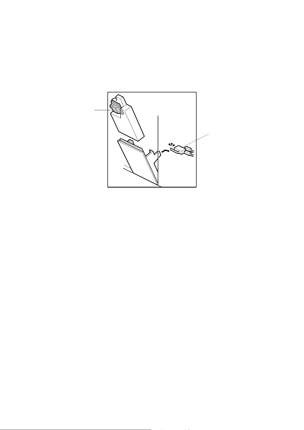
2.6.2 USED TONER COLLECTION
[A]
[B]
B047D101.WMF
B047/B048 copiers have a used toner overflow sensor [A] and a used toner cover
switch [B].
When the used toner overflow sensor detects that the used toner tank is full, the
overflow indicator begins blinking on the operation panel. 30 more meters (A1/D
size: 50 copies, SP51) can be copied. After that, the used toner overflow indicator
stays ON, and the machine will not operate.
The used toner cover switch detects when the used toner cover is open. “Door
open” is displayed on the operation panel, and the start key is disabled.
2-6
11 May, 2001 FUSING AND PAPER EXIT
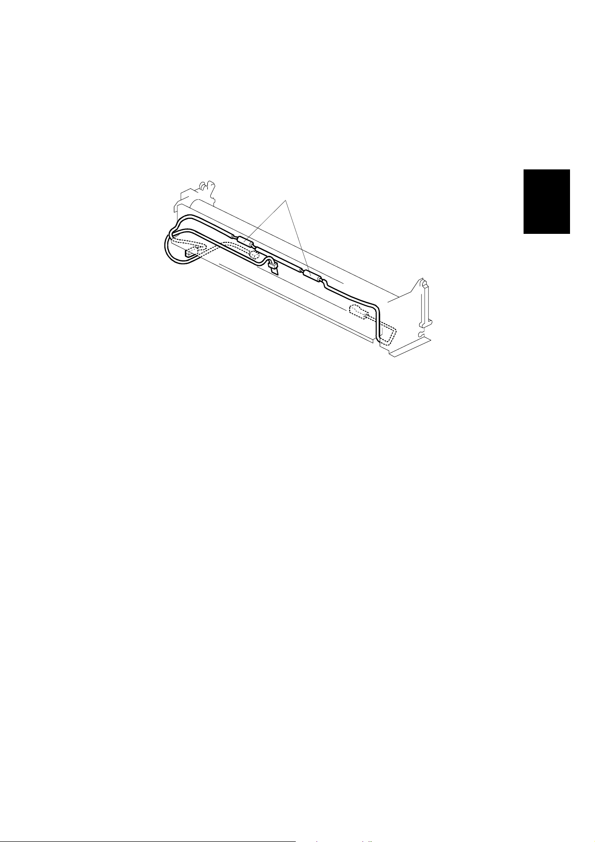
2.8 FUSING AND PAPER EXIT
2.8.1 OVERVIEW
[A]
Detailed
Descriptions
B047D102.WMF
Two thermofuses [A] (184°C, 192°C) keep the fusing unit from overheati ng .
Two thin-film thermistors measure the hot roller and pressure roller’s temperature.
The hot roller is a thin-shell, Teflon coated roller. The thinne r roller allows a much-
shorter warm-up time. However, extra care should be taken while working around
the hot roller. It is very easy to damage.
Like the A163/A251/A252 copiers, if the fusing temperature is lower than 60°C
when the main switch is turned on, the machine assumes that it has not been used
recently, and the main motor must rotate to generate the necessary triboelectric
charge on the toner and developer.
In the A163/A251/A252 copiers, the main motor begins rotating immediately.
However, the B047/B048 copiers have a thin shell hot roller and a contact
thermistor. When cold, the thermistor is hard and might damage the roller. The
machine waits until the hot roller temperature reaches 80°C. At that temperature
the thermistor softens and the hot roller can rotate safely.
Except for the differences listed above, the B047/B048 copiers are identical to the
A251 and A252 copiers. Please refer to A163/A251/A252 copier service manual for
additional details.
2-7

FUSING AND PAPER EXIT 11 May, 2001
2.8.3 TEMPERATURE CONTROL
Hot Roller Temperature Control
Hot Roller Temp. (°C)
198
190
180
170
160
150
142
Mode 8
Mode 7
Mode 6
Mode 5
Mode 4
Mode 3
Mode 2
Mode 1
~60
63 66 69 72 75 78 81 84 87 90 93 96 99 102105108111 114 117 120~
Pressure Roller Temp. (°C)
198
190
185
180
110 115 120 125 130 135 140 145
Lower Limit
Mode 8
Operating Temperature
Lower Limit
B047D001.WMF
The relationship between the hot roller and pressure roller temperatures has been
changed due to the thin-shell, Teflon coated roller.
2-8
11 May, 2001 ENERGY STAR COMPLIANT MACHINES (ALL THE DESTINATION)
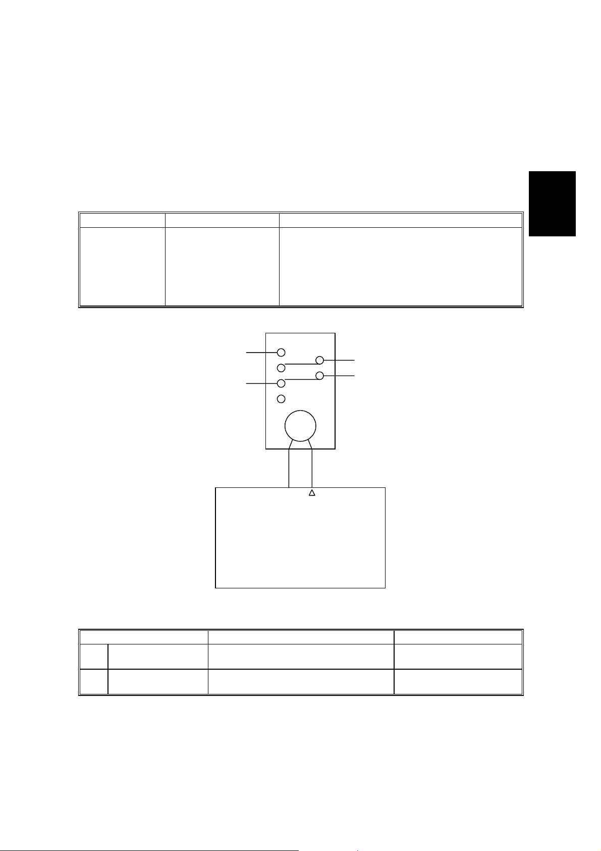
2.10 ENERGY STAR COMPLIANT MACHINES (ALL THE DESTINATION)
In conjunction with the modification for the Energy Star compliance, field
technicians need to understand the new operation modes, and must be able to
configure the machine for the customer’s specific environment/requirements. This
section lists all the differences between the Energy Star compliant machines and
the previous models.
Mode Non-Energy Star Energy Star
Starts timing once the last copy job is
complete. When the specified time has
Auto Off Mode Not available
passed, the copier turns off.
The time can be adjusted from 1 to 240
minutes.
Default: 30 minutes
RA
CN102
-A3
-B13
24]
[24]
!
AA
V
Detailed
Descriptions
Power Relay [
B047D002.WMF
Mode No. Function Data
Auto Shut-off Time
*15
Setting
AOF Auto off enable. 0: Disable
*33
Determines the auto shut-off time.
2-9
1 ← 30 → 240
1: Enable

11 May, 2001 INSTALLATION REQUIREMENTS
3. INSTALLATION
3.1 INSTALLATION REQUIREMENTS
3.1.1 ENVIRONMENT
1. Temperature Range:
2. Humidity Range: 20% to 80% RH
3. Ambient Illumination: Less than 1,500 lux (do not expose to direct
4. Ventilation: Room air should turn over at least 3 times per hour.
5. Ambient Dust: Less than 0.10 mg/m3 (2.7 x 10⁻⁶ oz/yd3)
6. If the location is air-conditioned or heated, place the machine as follows:
a) Where it will not be subjected to sudden temperature changes from low to
high, or vice versa.
b) Where it will not be directly exposed to cool air from an air conditioner in
the summer.
c) Where it will not be directly expos ed to heat.
7. Avoid exposure to corrosive gases.
8. Avoid installing anywhere higher than 2,000 m (6,500 ft) above sea level.
9. Place the machine on a strong and level base.
10. Avoid any area where the machine may be subjected to frequent, strong
vibration.
15°C to 30°C (50°F to 86°F)
sunlight).
Installation
3-1

INSTALLATION REQUIREMENTS 11 May, 2001
3.1.2 MINIMUM SPACE REQUIREMENTS
Back 600 mm
Left
600 mm
1. Front: 1,000 mm (39 in)
2. Back: 600 mm (24 in)
3. Right: 600 mm (24 in)
4. Left: 600 mm (24 in)
3.1.3 MACHINE LEVEL
Right
600 mm
Front 1,000 mm
B047I505.WMF
1. Front to back: Within 5 mm (0.2") of level
2. Right to left: Within 5 mm (0.2") of level
Make sure that the machine is level using a carpente r’s level.
3-2

11 May, 2001 INSTALLATION REQUIREMENTS
3.1.4 POWER SOURCE
Important:
The machine must be installed in a building/facility equipped with a protective
device such as a circuit breaker, as the machine relies on such devices for
protection against over-current and short circuits.
1. Input Voltage Level: 120 V, 60 Hz
More than 12 A (for U.S.A. version)
220 ~ 240 V, 50/60 Hz
More than 7 A (f or European version)
2. Permissible Voltage
±10%
Fluctuation:
3. Do not set anything on the power cord.
NOTE: 1) Make sure the plug is firmly inserted in the outlet.
2) Avoid multi-wiring.
Installation
3-3

INSTALLATION PROCEDURE 11 May, 2001
3.2 INSTALLATION PROCEDURE
3.2.1 COPIER
Accessory Check
Check the accessories and their quantities according to the following list:
- B048 copier -
Original Guides........................................................................ 6 pcs
Operating Instruction Holder.................................................... 1 pc
Operating Sheet ...................................................................... 1 pc
Caution Decal (-27 only).......................................................... 1 pc
Operating Instructions (-17 only).............................................. 1 pc
Original Guide Wire................................................................. 1 pc
- B047 copier -
Guide Wires............................................................................. 2 pcs
Copy Tray................................................................................ 1 pc
Copy Guide.............................................................................. 1 pc
Operating Instruction Holder.................................................... 1 pc
Operating Sheet ...................................................................... 1 pc
Caution Decal (-27 only).......................................................... 1 pc
Operating Instructions (-17 only).............................................. 1 pc
3-4
 Loading...