

Page 1
®
®
®
RICOH GROUP COMPANIES
A741
SERVICE MANUAL
PN: RCSM7030
Page 2

Page 3

®
®
®
SERVICE MANUAL
A741
RICOH GROUP COMPANIES
Page 4

Page 5

A741
SERVICE MANUAL
PN:RCSM7030
Page 6

Page 7

LEGEND
PRODUCT
CODE
GESTETNER RICOH SAVIN
A741 --- FW7030D ---
COMPANY
DOCUMENTATION HISTORY
REV. NO. DATE COMMENTS
* 7/98 Original Printing
Page 8

Page 9

CAUTION
DANGER OF EXPLOSION IF BATTERY IS INCORRECTLY REPLACED. REPLACE ONLY WITH THE SAME OR EQUIVALENT
TYPE RECOMMENDED BY THE MANUFACTURER. DISPOSE
OF USED BATTERIES ACCORDING TO THE MANUFACTURER’S INSTRUCTIONS.
ATTENTION
IL Y A DANGER D’EXPLOSION S’IL Y A REMPLACEMENT INCORRECT DE LA BATTERIE. REMPLACER UNIQUEMENT
AVEC UNE BATTERIE DU MÊME TYPE OU D’UN TYPE RECOMMANDÉ PAR LE CONSTRUCTEUR. METTRE AU RÉBUT
LES BATTERIES USAGÉES CONFORMÉMENT AUX INSTRUCTIONS DU FABRICANT.
Page 10

Page 11

Safety precautions
This booklet provides safety warnings and precautions for our service
personnel to ensure the safety of their customers, their machines as well
as themselves during maintenance activities. Service personnel are
advised to read this booklet carefully to familiarize themselves with the
warnings and precautions described here before engaging in
maintenance activities.
Page 12
Safety warnings and precautions
Various symbols are used to protect our service personnel and
customers from physical danger and to prevent damage to their
property. These symbols are described below:
DANGER: High risk of serious bodily injury or death may result from
insufficient attention to or incorrect compliance with warning
messages using this symbol.
WARNING: Serious bodily injury or death may result from insufficient
attention to or incorrect compliance with warning messages
using this symbol.
CAUTION: Bodily injury or damage to property may result from
insufficient attention to or incorrect compliance with warning
messages using this symbol.
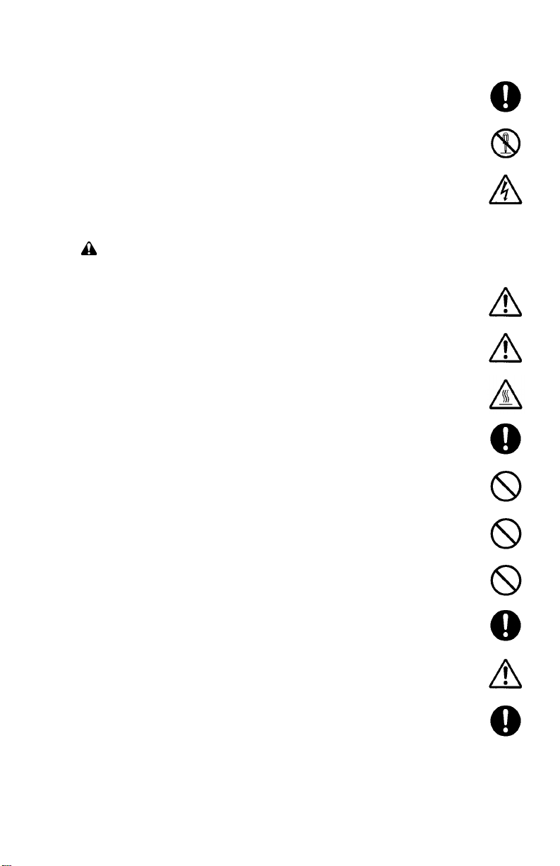
Symbols
The triangle (
and caution. The specific point of attention is shown inside
the symbol.
) symbol indicates a warning including danger
General warning.
Warning of risk of electric shock.
Warning of high temperature.
indicates a prohibited action. The specific prohibition is
shown inside the symbol.
General prohibited action.
Disassembly prohibited.
Page 13
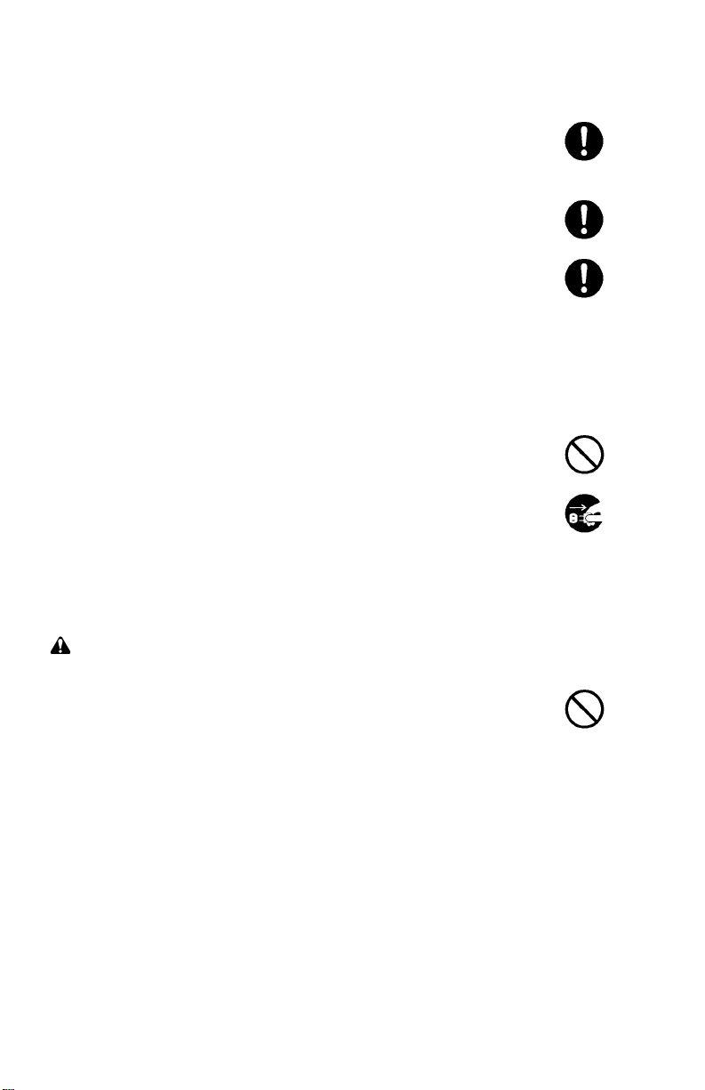
indicates that action is required. The specific action
required is shown inside the symbol.
General action required.
Remove the power plug from the wall outlet.
Always ground the copier.
1. Installation Precautions
WARNING
• Do not use a power supply with a voltage other than that specified.
Avoid multiple connections to one outlet: they may cause fire or electric
shock. When using an extension cable, always check that it is
adequate for the rated current. ...............................................................
• Connect the ground wire to a suitable grounding point. Not grounding
the copier may cause fire or electric shock. Connecting the earth wire
to an object not approved for the purpose may cause explosion or
electric shock. Never connect the ground cable to any of the following:
gas pipes, lightning rods, ground cables for telephone lines and water
pipes or faucets not approved by the proper authorities.........................
CAUTION:
• Do not place the copier on an infirm or angled surface: the copier may
tip over, causing injury. ...........................................................................
• Do not install the copier in a humid or dusty place. This may cause fire
or electric shock......................................................................................
• Do not install the copier near a radiator, heater, other heat source or
near flammable material. This may cause fire. .......................................
• Allow sufficient space around the copier to allow the ventilation grills to
keep the machine as cool as possible. Insufficient ventilation may
cause heat buildup and poor copying performance................................
Page 14
• Always handle the machine by the correct locations when moving it.....
• Always use anti-toppling and locking devices on copiers so equipped.
Failure to do this may cause the copier to move unexpectedly or
topple, leading to injury. ..........................................................................
• Avoid inhaling toner or developer excessively. Protect the eyes. If toner
or developer is accidentally ingested, drink a lot of water to dilute it in
the stomach and obtain medical attention immediately. If it gets into the
eyes, rinse immediately with copious amounts of water and obtain
medical attention.....................................................................................
• Advice customers that they must always follow the safety warnings and
precautions in the copier’s instruction handbook. ...................................
2. Precautions for Maintenance
WARNING
• Always remove the power plug from the wall outlet before starting
machine disassembly. ............................................................................
• Always follow the procedures for maintenance described in the service
manual and other related brochures. ......................................................
• Under no circumstances attempt to bypass or disable safety features
including safety mechanisms and protective circuits. .............................
• Always use parts having the correct specifications. ...............................
• Always use the thermostat or thermal fuse specified in the service
manual or other related brochure when replacing them. Using a piece
of wire, for example, could lead to fire or other serious accident............
• When the service manual or other serious brochure specifies a
distance or gap for installation of a part, always use the correct scale
and measure carefully. ...........................................................................
• Always check that the copier is correctly connected to an outlet with a
ground connection. .................................................................................
Page 15
• Check that the power cable covering is free of damage. Check that the
power plug is dust-free. If it is dirty, clean it to remove the risk of fire or
electric shock. .........................................................................................
• Never attempt to disassemble the optical unit in machines using lasers.
Leaking laser light may damage eyesight...............................................
• Handle the charger sections with care. They are charged to high
potentials and may cause electric shock if handled improperly..............
CAUTION
• Wear safe clothing. If wearing loose clothing or accessories such as
ties, make sure they are safely secured so they will not be caught in
rotating sections......................................................................................
• Use utmost caution when working on a powered machine. Keep away
from chains and belts..............................................................................
• Handle the fixing section with care to avoid burns as it can be
extremely hot..........................................................................................
• Check that the fixing unit thermistor, heat and press rollers are clean.
Dirt on them can cause abnormally high temperatures. .........................
• Do not remove the ozone filter, if any, from the copier except for
routine replacement. ...............................................................................
• Do not pull on the AC power cord or connector wires on high-voltage
components when removing them; always hold the plug itself...............
• Do not route the power cable where it may be stood on or trapped. If
necessary, protect it with a cable cover or other appropriate item. ........
• Treat the ends of the wire carefully when installing a new charger wire
to avoid electric leaks. ............................................................................
• Remove toner completely from electronic components. .........................
• Run wire harnesses carefully so that wires will not be trapped or
damaged.................................................................................................
Page 16
• After maintenance, always check that all the parts, screws, connectors
and wires that were removed, have been refitted correctly. Special
attention should be paid to any forgotten connector, trapped wire and
missing screws. ......................................................................................
• Check that all the caution labels that should be present on the machine
according to the instruction handbook are clean and not peeling.
Replace with new ones if necessary.......................................................
• Handle greases and solvents with care by following the instructions
below: .....................................................................................................
· Use only a small amount of solvent at a time, being careful not to
spill. Wipe spills off completely.
· Ventilate the room well while using grease or solvents.
· Allow applied solvents to evaporate completely before refitting the
covers or turning the main switch on.
· Always wash hands afterwards.
• Never dispose of toner or toner bottles in fire. Toner may cause
sparks when exposed directly to fire in a furnace, etc..........................
• Should smoke be seen coming from the copier, remove the power
plug from the wall outlet immediately. ..................................................
3. Miscellaneous
WARNING
• Never attempt to heat the drum or expose it to any organic solvents
such as alcohol, other than the specified refiner; it may generate toxic
gas. .........................................................................................................
Page 17

CONTENTS
I THEORY AND CONSTRUCTION SECTION
1-1 Specifications
1-1-1 Specifications ................................................................................ 1-1-1
1-2 Handling Precautions
1-2-1 Handling and storage of the drum ................................................. 1-2-1
1-2-2 Storage of developer and toner..................................................... 1-2-1
1-2-3 Handling of the heaters ................................................................. 1-2-1
1-2-4 Storage of paper ........................................................................... 1-2-1
1-3 Mechanical Construction
1-3-1 Part names and functions ............................................................. 1-3-1
1-3-2 Copy process ................................................................................ 1-3-3
1-3-3 Machine cross sectional view........................................................ 1-3-3
1-3-4 Machine drive system ................................................................... 1-3-4
1-3-5 Mechanical construction of each section ...................................... 1-3-8
II ELECTRICAL SECTION
2-1 Electrical Parts Layout
2-1-1 Electrical parts layout .................................................................... 2-1-1
2-2 Detection of Paper Misfeed
2-2-1 Paper misfeed detection ............................................................... 2-2-1
2-2-2 Paper misfeed detection conditions .............................................. 2-2-2
2-3 Operation of the PCBs
2-3-1 Power source PCB ........................................................................ 2-3-1
2-3-2 LPH power supply PCB................................................................. 2-3-7
2-3-3 Servo motor control 1 PCB ......................................................... 2-3-10
2-3-4 Servo motor control 2 PCB ......................................................... 2-3-13
2-3-5 Main PCB .................................................................................... 2-3-16
2-3-6 Backup PCB ................................................................................ 2-3-25
2-3-7 ISU PCB ...................................................................................... 2-3-26
2-3-8 Operation unit PCB ..................................................................... 2-3-29
2-3-9 Inverter PCB................................................................................ 2-3-30
340
III SET UP AND ADJUSTMENT SECTION
3-1 Installation
3-1-1 Unpacking and installing the copier .............................................. 3-1-1
3-1-2 Copy mode initial settings ........................................................... 3-1-27
3-1-3 Installing the key counter (optional) ............................................ 3-1-28
3-1-4 Attaching a roll unit heater (optional) .......................................... 3-1-31
3-2 Simulation
3-2-1 Simulation function ........................................................................ 3-2-1
3-3 Assembly and Disassembly
3-3-1 Cautions during disassembly and assembly ................................. 3-3-1
3-3-2 Paper feed section ........................................................................ 3-3-3
3-3-3 Main charger section ................................................................... 3-3-10
3-3-4 Exposure and original feed section ............................................. 3-3-19
3-3-5 Developing section ...................................................................... 3-3-31
1-1-1
Page 18

340
3-3-6Transfer/separation section......................................................... 3-3-37
3-3-7Cleaning section.......................................................................... 3-3-42
3-3-8Fixing section.............................................................................. 3-3-48
3-3-9Other sections............................................................................. 3-3-60
3-4PCB Initial Settings
3-4-1Main PCB...................................................................................... 3-4-1
3-4-2Non-field-adjustable volume controls............................................ 3-4-3
3-5Self Diagnostics
3-5-1Self-diagnostic function................................................................. 3-5-1
3-6Troubleshooting
3-6-1Image formation problems............................................................ 3-6-1
3-6-2Paper misfeeds........................................................................... 3-6-17
3-6-3PCB terminal voltages................................................................. 3-6-23
3-6-4Electrical problems...................................................................... 3-6-38
3-6-5Mechanical problems.................................................................. 3-6-51
3-7Appendixes
Timing chart No. 1...................................................................................... 3-7-1
Timing chart No. 2...................................................................................... 3-7-2
Timing chart No. 3...................................................................................... 3-7-3
Timing chart No. 4...................................................................................... 3-7-4
Timing chart No. 5...................................................................................... 3-7-5
Operation unit PCB..................................................................................... 3-7-6
Power source PCB 1/2................................................................................ 3-7-7
Power source PCB 2/2................................................................................ 3-7-8
Detachable unit wiring diagram................................................................... 3-7-9
1-1-2
Page 19

I
THEORY AND
CONSTRUCTION
SECTION
Page 20

Page 21

CONTENTS
1-1 Specifications
1-1-1 Specifications ...................................................................................... 1-1-1
340
1-1-5
Page 22

Page 23

1-1-1 Specifications
Type ……………………………Console type
Copying method ……………… Dry indirect electrostatic photocopying
Original type …………………… Sheet
Original feed method ………… Moving originals
Paper …………………………… (1) Plain paper: 64 – 80 g/m2 (fed from the roll unit or
bypass table)
(2) Special paper: Tracing paper, film (fed from the roll
unit or bypass table)
Roll paper size ………………… Width: 420 – 920 mm/17" – 36"
Diameter: 180 mm/61/4" maximum
Inner diameter: 76 mm/3"
Length: 175 m
Original sizes …………………Standard: A0 – A4R (64 – 80 g/m2)
36" × 48" – 81/2" × 11" (64 – 80 g/m2)
Maximum: 920 (w) × 5,000 (l) mm (64 – 80 g/m2)
36" × 197" (64 – 80 g/m2)
Copy sizes …………………… Standard: A0 – A4R (64 – 80 g/m2)
36" × 48" – 81/2" × 11" (64 – 80 g/m2)
Maximum: 920 (w) × 5,000 (l) mm (64 – 80 g/m2)
36" × 197" (64 – 80 g/m2)
Effective image width: 920 mm
Leading edge margin: 5 ± 4 mm
Copying magnification
ratios …………………………… Manual mode: 25 – 400%
(at intervals of 1% or 0.1%)
Auto copy mode:
Fixed ratios according to the original and paper
sizes
Metric:
1:1±0.5%, 1:4.000, 1:2.829, 1:2.000, 1:1.410,
1:0.706, 1:0.500, 1:0.352, 1:0.250
Inch (Architecture):
1:1±0.5%, 1:3.143, 1:2.588, 1:2.000, 1:1.294,
1:0.640, 1:0.500, 1:0.324, 1:0.250
Inch (Engineer):
1:1±0.5%, 1:4.000, 1:2.667, 1:2.000, 1:1.333,
1:0.667, 1:0.500, 1:0.333, 1:0.250
Copying speed ………………… 4.8 m/min
First copy time …………………30 s maximum (A1 standard size copying)
Warmup time …………………10 min maximum (room temperature 20°C/68°F,
65% RH)
Paper feed system …………… Automatic feed from the roll unit and manual feed from
the bypass table
Consecutive copying …………1 – 20 copies (when the original length is 1300 mm
or less)
340
1-1-1
Page 24

340-1
Photoconductor ………………OPC (Drum diameter: 90 mm)
Charging system ………………Single plus corona charging
Drum surface potential: 870 ± 50 V DC
Exposure system ……………… Moving original scanning
Light source …………………… Fluorescent lamp, 65 W
Developing system …………… Dry (magnetic brush)
Developer: Dual-component (ferrite carrier and black
toner: N22T)
Toner density control: Toner sensor
Toner replenishing: Automatic supply from the toner
hopper
Transfer system ……………… Single negative corona charging: –5.3 kV DC
Separation system …………… Single AC corona charging: 5.6 kV AC
Fixing system …………………Heat roller
Heat source: Halogen heaters
120 V areas: 800 W (main), 400 W (sub)
220 – 240 V areas: 1120 W (main), 480 W (sub)
Control temperature: 150°C/302°F (plain paper or film)
145°C/293°F (tracing paper)
Abnormal temperature increase-prevention device:
Thermostat, 145°C/293°F
Fixing pressure: 2.0 N at both ends, 5.9 N at center
Charge erasing system ……… Exposure by cleaning lamp
Cleaning system ………………Cleaning blade and cleaning fur brush
Functions ……………………… (1) Preheat/energy saving
(2) Auto clear (can be set to between 30 and 270 s at
intervals of 30 s)
(3) Auto shutoff (can be set to between 15 and
120 min at intervals of 15 min)
(4) Self-diagnostics
(5) Simulation
(6) Margin copy
(7) Hanging copy
(8) Program copy
(9) Preview copy
(10) Paper cut length setting
(11) Same-size/full-size magnification adjustment
(12) Fixing temperature adjustment
(13) Initial settings change
(14) Original size detection
(15) Paper size detection
Power requirement …………… 120 V AC, 60 Hz, 13 A
220 – 240 V AC, 50/60 Hz, 8 A
Power consumption ……………
Machine dimensions …………1355 (w) × 635 (d) × 1107 (h) mm
Weight …………………………Approx. 268 kg, 590.3 lb. (main unit only)
Floor requirement …………… 1355 (w) × 707 (d) mm, 533/8" (w) × 2713/16" (d)
1500
W (120 V areas)
1900
W (220 – 240 V areas)
533/8" (w) × 25" (d) × 439/16" (h)
1-1-2
Page 25

Accessories ……………………Original reversing guide
Optional accessories ………… 3rd roll unit, roll shaft, carrier sheets (A0, A1, A2), key
counter and original support
3rd roll unit (optional)
Type ……………………………Built-in type
Paper …………………………… Equivalent to the copier to be connected to
Power source …………………Electrically connected to the copier
340
1-1-3
Page 26

Page 27

CONTENTS
1-2 Handling Precautions
1-2-1 Handling and storage of the drum ....................................................... 1-2-1
1-2-2 Storage of developer and toner .......................................................... 1-2-1
1-2-3 Handling of the heaters ....................................................................... 1-2-1
1-2-4 Storage of paper ................................................................................. 1-2-1
340
1-1-7
Page 28

Page 29

340
1-2-1 Handling and storage of the drum
Use the following caution when handling the drum.
• When removing the drum from the main unit, make sure not to expose it to direct sunshine
or strong lighting.
• Store the drum where the ambient temperature is kept between –20°C/–4°F and 40°C/
104°F and humidity around 85%RH. Sudden changes in temperature and humidity even
within the permitted ranges should be avoided, too.
• Avoid atmosphere laden with substances that might chemically damage the drum surface.
• Never hit the drum surface with anything hard or pointed. Protect it from bare or gloved
hands; if it is accidentally touched, clean by following the proper procedure.
1-2-2 Storage of developer and toner
Store developer and toner in a cool, dark place free from direct sunshine or high humidity.
1-2-3 Handling of the heaters
This copier is equipped with heaters to avoid condensation inside. These heaters are kept
powered as long as the copier power cable is connected to a wall outlet with the main switch
set off. Never disconnect the power cable if the copier is used in a humid place of 70%RH
higher.
If the copier is not going to be used for long periods of time, disconnect the power cable from
the wall outlet.
Each roll unit of this copier is equipped with a roll unit heater*1 which can be individually
turned on or off with a switch. If normal plain paper is kept in the roll units and there is a risk
of high humidity, keep their heaters on. However, keep the heater off if tracing paper is kept
in the roll unit.
1-2-4 Storage of paper
Paper should be stored in a cool, dark place free from high temperature or humidity. If it is
not going to be used for a long time, take paper out of the roll unit, put it in the original
wrapping paper and seal.
*1 Optional for 220 – 240 V models.
1-2-1
Page 30

Page 31

CONTENTS
1-3 Mechanical Construction
1-3-1 Part names and functions ................................................................... 1-3-1
1-3-2 Copy process ...................................................................................... 1-3-3
1-3-3 Machine cross sectional view ............................................................. 1-3-3
1-3-4 Machine drive system ......................................................................... 1-3-4
(1) Drive system 1 (driven by the paper feed motor) ........................ 1-3-4
(2) Drive system 2 (driven by the paper feed motor) ........................ 1-3-5
(3) Drive system 3 (driven by the drum motor and fixing
drive motor) ................................................................................. 1-3-6
(4) Drive system 4 (driven by the drive motor and toner
feed motor) .................................................................................. 1-3-6
(5) Drive system 5 (driven by the original feed motor) ...................... 1-3-7
1-3-5 Mechanical construction of each section ............................................ 1-3-8
(1) Paper feed section ...................................................................... 1-3-8
Winding operation of paper roll ................................................. 1-3-10
(1-1) Bypass paper feed .......................................................... 1-3-12
(1-2) Roll unit paper feed ........................................................ 1-3-13
(2) Main charger section ................................................................. 1-3-15
Drum surface potential correction ............................................. 1-3-18
(3) Exposure and original feed section ........................................... 1-3-19
(4) CIS and LPH section ................................................................. 1-3-22
Original image reading .............................................................. 1-3-24
Static latent image formation..................................................... 1-3-24
CIS correction............................................................................ 1-3-26
(5) Developing section .................................................................... 1-3-28
Forming the magnetic brush...................................................... 1-3-29
Temperature compensation of the toner sensor output ............ 1-3-30
Toner sensor output correction based on the copy count ......... 1-3-31
Toner density control................................................................. 1-3-32
(6) Transfer/separation section ....................................................... 1-3-33
(7) Cleaning section ........................................................................ 1-3-36
(8) Static eliminator section ............................................................ 1-3-39
(9) Fixing section ............................................................................ 1-3-41
Heating and temperature control of heat roller and
press roller................................................................................. 1-3-43
340
1-1-9
Page 32

Page 33

1-3-1 Part names and functions
!
0
9
ˆ
340
@#
$
%
8
ˆ
3
4
fi›
5
6
7
°
8
&
^
3
2
1
‚
‡
Œ
„
fl
Figure 1-3-1
´
·
Á
‰
¨
ˇ
1 Main switch
2 Total counter
3 Front covers
4 Carrier sheet guides
5 Copy bins
6 Bypass slot
7 Bypass table
8 Main body release levers
9 Original guide
0 Paper eject guides
*1 Optional.
*2 Optional for 220 – 240 V models.
! Original table
@ Original loop guide
# Original insert slot
$ Copy eject slot
% Operation panel
^ Right cover
& Key counter
* Copy ready indicator
(ready lamp)
( Fuser release button
*1
) Original holding section
⁄ Original holder anchor pins
¤ Upper rear cover screws
‹ Upper rear cover
› Transport knob
fi Waste toner tank
fl Copy bin stopper plates
‡ Second roll unit
— First roll unit
· Instruction handbook box
‚ Roll unit handle
ΠPaper roll insertion cover
„ Paper roll insertion latches
´ Roll unit heater switch
‰ Paper roll shaft
ˇ Paper roll size label
Á Paper roll release lever
¨ Paper roll shaft gear
ˆ Copy eject slot guides
*2
1-3-1
Page 34

340-3
Metric Inch
‡flfi
°
·
!
#
%
1
2
^
3
$
@
⁄
1234567
)
¤
(
*
123
456
789
0
.
6
&
5
‹
›
9
‚
Œ
7
„
·
#
^
°
!
%
8
1
0
2
3
4
@
¤
$
⁄
‡
Add
Paper
Add
Toner
Mainte-
nance
Image Proc ess
Border
Erase
Mirror
Negative
Synchro
Paper
Length
1
Paper
2
Source
3
Material
Vellum
Film
Full Size
APS
AMS
Preset
R E
Zoom
Indepen-
dent
Zoom
Copy Contrast
Bold
Print
Light
Print
1234567
Dark
)
*
Half
Tone
Auto
fl
Leading
Edge
Trailing
123
456
789
Light
0
(
&
Leading
Left
6
Margin
.
Enter
Stop
5
fi
Clear
Fusing
Temp .
Adjusted
Added
Features
Memory
Recall
Interrupt
Memory
Copy
On-Line
Energy
Saver
Preview
Copy
Reset
Job Stop
Roll Cut
‹
9
Œ
8
1
3
›
‚
7
„
0
2
4
1-3-2
1 Preheat/energy saver key/indicator
2 Preview copy key
3 All clear/reset key
4 Job stop/roll cut key
5 Stop/clear key
6 Numeric keys
7 Mode set keys
8 Enter key
9
Leading edge margin key/indicators
0 Left margin key/indicators
! Leading edge hanging key/indicators
Figure 1-3-2 Operation panel
@ Trailing edge hanging key/indicators
# Copy mode select key/indicators
$ Zoom mode select key/indicators
% Paper length key/indicators
^ Paper source key/indicators
& Auto/manual contrast select key/indicators
* Copy contrast keys
( Copy contrast indicators
) Original contrast key/indicators
⁄ Special paper select key/indicators
¤ Image process select key/indicators
‹ Added features key
› Memory recall key
fi Fusing temp. adjusted indicator
fl Display
‡ Add paper indicator
— Add toner indicator
· Maintenance indicator
‚ Interrupt key/indicator
ΠMemory copy key/indicator
„
On-line key/indicator
Page 35

340
1-3-2 Copy process
1 Exposure
Fluorescent lamp
3 Static latent
5 Developing
Paper
image formation
Toner
LPH
Drum
Original
2 Original image reading
CIS
Original image data read by the
CIS is A/D converted and
image-processed, and the LPH
LEDs light to form a static latent
image on the drum surface.
4 Main charging
8 Fixing
1-3-3 Machine cross sectional view
3
4
5
6
1
2 8
8
7
9
6 Transfer 7 Separation
Figure 1-3-3 Copy process
*1: The third roll unit is optional.
Figure 1-3-4 Machine cross sectional view
1 Paper feed section (page 1-3-8)
2 Main charger section (page 1-3-15)
3 Exposure and original feed section (page 1-3-19)
4 CIS and LPH section (page 1-3-22)
5 Developing section (page 1-3-28)
6 Transfer/separation section (page 1-3-33)
7 Cleaning section (page 1-3-36)
8 Static eliminator section (page 1-3-39)
9 Fixing section (page 1-3-41)
1-3-3
Page 36

340-1
1-3-4 Machine drive system
(1) Drive system 1 (driven by the paper feed motor)
4
$
@
3
2
1
5
8
6
7
0
›
·
´
!
‹
⁄
¤
„
)
°
Œ
#
‚
(
%
9
‰
fi
^
ˇ
fl
‡
Á
&
*
1 Paper feed motor pulley 15/18
2 Cutter drive belt
3 Drive tension pulley
4 Cutter drive pulley 20
5 SB gear 37
6 Cutter clutch gear
7 Cutter drive gear 21
8 Duplex gear 32
9 Paper feed section drive belt 1
0 Drive tension pulley
! Paper feed pulley 16
@ Pre-transfer drive gear
# Optical section idle gear 46
$ Roll paper conveying clutch gear
% Idle gear 45
^ Paddle gear
& Optical section idle gear 46
* SB gear 37
*1: Parts 29 to 36 are present when the third roll unit (optional) is installed.
( Bypass registration clutch gear
) Gear 50T
⁄ Registration clutch gear
¤ Paper feed pulley 16
‹ Idle gear 36/30
› Middle feed clutch gear
fi Optical section idle gear 46
fl Idle gear 20/26
‡ Middle roll winding clutch gear
— Pulley 20P5
· Paper feed section drive belt 2
‚ Pulley 20P5
ΠPaper feed pulley 16
„ Idle gear 36/30
´ Lower feed clutch gear
‰ Optical section idle gear 46
ˇ Idle gear 20/26
Á Lower roll winding clutch gear
*1
*1
*1
*1
*1
*1
*1
*1
1-3-4
Figure 1-3-5 Drive system 1 (outer side to the left frame)
Page 37

(2) Drive system 2 (driven by the paper feed motor)
340-1
5
4
3
2
7
6
9
8
1
(
)
0
!
@
⁄
¤
#
›
%
‹
fi
$
^
&
*
1 Cutter drive gear 21
2 Cutter gear 32
3 Eject gear 29
4 Fixing unit idle gear 24T
5 Duplex gear 32
6 Drive gear 20T
7 Drive gear 20T
8 Paper feed pulley gear B
9 Paper feed pulley gear B
0 Idle gear 22
! Paper feed pulley gear B
@ Upper roll winding clutch gear
# Drive gear 20T
*1: Parts 24 and 25 are present when the third roll unit (optional) is installed.
$ Idle gear 16/25
% Duplex gear 32
^ Roll idle gear A
& Spiral roller gear 23
* Roll gear 40
( Duplex gear 32
) Upper feed clutch gear
⁄ Drive gear 20T
¤ Roll drive gear 16
‹ Roll gear 40
› Roll drive gear 16
fi Roll gear 40
*1
*1
Figure 1-3-6 Drive system 2 (inner side from the left frame)
1-3-5
Page 38

340
(3) Drive system 3 (driven by the drum motor and fixing drive motor) (4) Drive system 4 (driven by the drive motor and toner feed motor)
(
*
&
9
1
2
0
3
4
!
5
8
6
7
^
%
¤
*
#
‹
$
(
&
@
)
⁄
%
$
#
@
^
!
0
9
1
3
2
5
4
6
7
8
1-3-6
Figure 1-3-7 Drive system 3 (outer side to the left frame)
1 Main drive pulley
2 Drive tension pulley
3 Pre-transfer drive belt
4 Pre-transfer drive pulley 32
5 Developer gear
6 Drum motor gear 17
7 Drum drive gear 45
8 Drum drive gear 60
9 Developing unit drive belt
0 Tension pulley
! Developing unit drive pulley 16
@ Fixing drive motor gear
# Fixing section drive gear
$ Developer gear 22
% Idle gear 34
^ Idle gear 26
& SB gear 24
* Heat roller gear
( Fixing gear 24
) Idle gear 22
⁄ Sleeve gear 17
¤ Fixing unit idle gear
‹ Gear 27T
Figure 1-3-8 Drive system 4 (inner side from the left frame)
1 Pre-transfer drive gear 22
2 Drive gear 20T
3 Pre-transfer gear 30
4 Drum joint
5 Left drum flange
6 Feed gear 25
7 Fur brush gear 17
8 Roll unit gear 18
9 Developing unit drive gear 20
0 Developing roller gear 19
! Developing unit idle gear 17
@ Developer paddle gear
# Spiral roller gear 23
$ Toner shaft gear
% Toner shaft gear
^ Fixing idle gear
(left side of the machine)
& Toner feed motor gear
(right side of the machine)
* Toner gear 34
( Toner gear 34
Page 39

(5) Drive system 5 (driven by the original feed motor)
340
0
!
6
9
8
7
5
4
Figure 1-3-9 Drive system 5 (outer side to the right frame)
1 Original feed motor pulley
2 Original feed drive belt 1
3 Idle pulley 16
4 Tension pulley
5 Original feed clutch gear
6 Developing unit pulley
7 Front lower original roller
8 Front upper original roller
9 Original feed pulley
0 Original feed drive belt 2
! Original feed pulley
3
2
1
1-3-7
Page 40

340
1-3-5 Mechanical construction of each section
(1) Paper feed section
The paper feed section is comprised of the parts shown in Figure 1-3-10. Paper can be fed
either manually or automatically from a paper roll.
In the paper feed section, a sheet of paper fed from the roll unit or placed on the bypass table
is conveyed to the transfer section in synch with the LED on timing of the LPH section.
2
7
1
9
8
0
*
´
∏
(
¤
‚
Œ
Å
)
Á
„
·
Ø
6
!
3
°
ˆ
‡
^
&
¨
5
%
⁄
$
fl
ˇ
‹
4
@
#
›
fi
‰
1-3-8
Figure 1-3-10 Paper feed section
Page 41

340
1 Registration upper guide
2 Bypass pulley
3 Registration lower guide
4 Bypass table
5 Bypass registration roller
6 Registration roller
7 Cutter eject rear guide
8 Registration pulley
9 Cutter unit
0 Cutter rear guide
! Cutter front guide
@ Roll lever
# Roll base A
$ Paper roll shaft
% Roll paper feed upper guide A
^ Roll paper feed upper roller
& Roll paper feed lower roller A
* Roll paper conveying rear roller A
( Roll paper conveying front roller
) Roll stay A
¤ Roll paper conveying upper guide
‹ Center partition
› Roll lever
fi Roll base B
fl Paper roll shaft
‡ Roll paper feed upper guide B
— Roll paper feed upper roller
· Roll front guide B
‚ Roll rear guide B
ΠRoll paper conveying rear roller B
„ Roll paper conveying lower guide
´ Roll paper conveying rear guide
‰ Roll lever
ˇ Paper roll shaft
Á Roll base B
*1
*1
*1
¨ Roll paper feed upper guide B
ˆ Roll paper feed upper roller
Ø Roll front guide B
” Roll rear guide B
*1
*1
Å Roll paper conveying rear roller C
⁄ Roll paper feed lower guide A
*1 Parts 34 to 41 are present when the third roll unit (optional) is installed.
MPCB
CN3-14
CN3-34
CN6-14
CN6-7
CN3-11
CN6-8
CN7-12
CN7-13
CN6-9
CN3-9
CN4-8A
CN3-10
CN4-9A
CN7-14
CN3-26
CN3-28
CN3-29
CN6-10
CN7-16
CN6-11
CN7-15
CN6-12
CN7-17
CN6-13
PFM SPEED1
PFM SPEED2
PFM ENA
CHPSW1
CHPSW2
CN3-1
CN3-5
DCM2PCB
RCL
RSW
RPCCL
FCL-U
RLDSW-M
PFM
RLDSW-L
PS-U
FCL-L
BYPTIMSW
BYP
CCL
RCL
RLDSW-U
RWCL-U
PS-M
FCL-M
PS-L
BYPRSW
RWCL-M
RWCL-L
*1
*1
*1
Figure 1-3-11 Block diagram of the paper feed section
1-3-9
Page 42

Paper Feed Drive
The paper feed motor drives the paper feed rollers through electromagnetic clutches. When the feed
clutch is off and the roll winding clutch is on, the paper spool reverses to pull back the roll leading
edge the home position.
Paper Roll and Original Width Detection
Two sensors, paper size switches 1 and 2, detect the roll width. The original width is also detected by
two sensors, original size switches 1 and 2. Depending on the sensor status and UP setting, the
machine can detect the widths of 17.0”, 22.0” 34.0 (Engineering) or 18.0”, 24.0”, 36.0” (Architecture).
The paper leading edge switch is used only to detect the leading edge of roll paper.
Roll End
When the pulse disk on the roll winding clutch shaft stops rotation while the paper feed motor is on,
the machine detects a roll end condition. If the paper leading edge sensor is on when roll end is
detected, the cut ter clutch is energized to cut the p aper.
Upper Feed Clutch
Pulse Disk
Upper Roll Winding
Clutch
Paper Feed Motor
Middle Feed Clutc h
Middle Roll Windin g Clutch
Lower Feed Clutch
Pulse Disk
Pulse Disk
Original Size Switch1
Original Size Switch 2
Upper Paper Lea ding Edge Detect ion S witch
Middle Paper Leading Edge Detection Switch
Upper Paper Size Switch1
Lower Paper Size Sw itch
Lower Paper Lea ding Edge Detecti on S witch
Lower Roll Wind ing Clutch
Upper Paper
Size Switch
Lower Paper
Size Switch
1-3-9-1
Page 43

Paper Transport
The by-pass registrati on clutch and the by- pass registration switch are used to contr ol the paper feed
timing.
For roll feeding, the feed clutch, roll paper conveying clut ch, reg istration clutch, and registration switch
control the paper feed timing. The paper feed length is measured by the registration sensor on time.
Initially, the paper feed motor is slightly faster than the drive motor which drives the pre-transfer drive
roller. This is to make a buckle between the registration roller and the pre-transfer drive roller. This
buckle absorbs the vibration when the paper is cut, to prevent jitter at the image transfer section. After
a buckle is made, the paper feed motor speed becomes the same as the drive motor speed.
Cutter Unit
The paper feed motor drive is transmitted to the cutter clutch through gears and a timing belt. The
rotary cutter rotates when the cutter clutch is energized. Initially, the cutter is in the home position, and
the cutter functions as a paper guide in this position. After the paper leading edge enters the c utter
unit, the cutter moves to the cutting ready position. After the paper is cut, the cutter returns to the
home position. Paper transportation does not stop during cutting.
Cutter Clutch
Roll Paper Conve yi ng Clutch
Feed Clutch
Cutting Ready Po s ition
Interrupted
Not Interru p te d
Cutter Home Position
Registratio n Clutch
By-Pass Registration Clutch
Cutter Blade
Home Position
Cutting Ready Posit ion
1-3-9-2
Page 44

340
Winding operation of paper roll
The leading edge of the paper in the roll unit is first fed to the home position (copy ready
position) by the winding operation, where it is ready for copying.
• After the following operations, if the leading edge of the paper roll is not at the home
position, the winding operation for that roll unit will be performed.
1) After pressing the all clear/reset key.
2) After performing the auto clear function.
3) After changing the paper feed position with the paper source key.
4) One minute after a copy cycle ends and the ready lamp (copy ready indicator) lights.
(If any key is pressed after the ready lamp is lit, another minute will be counted after
the key press.)
5) After opening/closing the right cover (cycling safety switch 3), the main body
(cycling safety switches 4 and 5), or the upper rear cover (cycling safety switch 6).
• After the following operation, the winding operation for all the roll units will be performed.
(Winding starts with the lowest roll unit.)
1) After opening/closing the front covers (cycling safety switches 1 and 2).
• With the roll paper leading edge detection switch off
Off
PFM
RLDSW-U
FCL-U
On
Off
On
a
On
b
100 ms
Off
Timing chart 1-3-1 Winding operation for the first roll unit (1)
a The paper feed motor (PFM) and the upper feed clutch (FCL-U) turn on, and the paper
is conveyed in the feed direction.
b The upper feed clutch (FCL-U) and the paper feed motor (PFM) are turned off 100 ms
after the upper roll paper leading edge detection switch (RLDSW-U) is turned on, and
the leading edge of the paper stops at the home position (copy ready position).
• Winding operation for the 2nd and 3rd roll units is performed similarly.
1-3-10
Page 45

340
• With the roll paper leading edge detection switch on
Off
PFM
RWCL-U
RLDSW-U
FCL-U
On
On
a
Off
On
Off
b
On
c
100 ms
Off
Timing chart 1-3-2 Winding operation for the first roll unit (2)
a The paper feed motor (PFM) and the upper roll winding clutch (RWCL-U) are turned on,
and the paper starts to wind.
b After the upper roll paper leading edge detection switch (RLDSW-U) turns off, the upper
roll winding clutch (RWCL-U) turns off and the upper feed clutch (FCL-U) turns on, and
the paper is conveyed in the feed direction.
c 100 ms after the upper roll paper leading edge detection switch (RLDSW-U) turns on,
the upper feed clutch (FCL-U) and the paper feed motor (PFM) turn off, and the leading
edge of the paper stops at the home position (copy ready position).
• Winding operation for the 2nd and 3rd roll units is performed similarly.
1-3-11
Page 46

340
(1-1) Bypass paper feed
Paper insertion
BYPRSW: On
BYPTIMSW: On
Original insertion
OLDSW: On
OTDSW: On
BYPTIMSW: Off
Off
Off
e
Off
Off
Off
PFM
BYPRCL
OLDSW
BYPRSW
OTDSW
BYPTIMSW
PSYNC
signal
On
1.75 s
On
750 ms
ab
On
On
Timing chart 1-3-3 Bypass paper feed
Off
574 ms
On
d
On
450 ms
c
Potential buildup completed.
Primary original feed completed.
Shading correction completed.
With the paper inserted before the original.
200 ms
Off
a 1.75 s after the bypass registration switch (BYPRSW) is turned on by inserting paper into
the bypass table, the paper feed motor (PFM) and the bypass registration clutch
(BYPRCL) turn on, and feeding of the inserted paper starts.
b 750 ms after the bypass timing switch (BYPTIMSW) turns on, the bypass registration
clutch (BYPRCL) turns off, and the paper stops at the copy ready position.
c Potential buildup, primary original feed and then shading correction are completed. 450
ms after these secondary paper feed start conditions are satisfied, the PSYNC signal
turns on.
d The bypass registration clutch (BYPRCL) turns on to convey the paper to the transfer
section.
e 200 ms after the paper is conveyed to the transfer section and the bypass timing switch
(BYPTIMSW) turns off, the bypass registration clutch (BYPRCL) turns off, and the paper
feed operation is completed.
1-3-12
Page 47

(1-2) Roll unit paper feed
Original insertion
OLDSW: On
OTDSW: On
RSW: On
CHPSW: On
OLDSW: Off
340
RSW: Off
CHPSW: Off
PFM
RCL
CCL
OLDSW
RSW
RPCCL
PCSW
OTDSW
FCL-U/M/L
CHPSW1, 2
OFCL
PSYNC
signal
a
On
Off
e
574 ms
d
On
On
78 P
On
c
On
375 ms
On
b
On
On
450 ms 600 ms
Off
1 s
Off
On
Potential buildup completed.
Primary original feed completed.
Shading correction completed.
Timing chart 1-3-4 Roll unit paper feed
On
Off
Off
h
200 ms
Off
Off
g
f
a 1 s after the original is inserted and the original trailing edge detection switch (OTDSW)
is turned on, the paper feed motor (PFM), the paper feed clutch for currently selected roll
unit [the upper/middle/lower feed clutches (FCL-U/M/L)], the roll paper conveying clutch
(RPCCL), and the registration clutch (RCL) are turned on to start feeding the paper in
the selected roll unit.
b The paper turns the registration switch (RSW) on. After 375 ms, the paper feed clutch
[upper/middle/lower feed clutch (FCL-U/M/L)], the roll paper conveying clutch (RPCCL),
and the registration clutch (RCL) are turned off and the paper stops. The cutter clutch
(CCL) is then turned on and the cutter starts to move to the ready position and primary
paper feed is completed.
c After the cutter home position switches (CHPSW 1 and 2) are turned on, the cutter clutch
(CCL) is turned off and the cutter stops at the ready position.
1-3-13
Page 48

340
d Potential buildup, primary original feed and then shading correction are completed. 450
ms after these secondary paper feed start conditions are satisfied, the PSYNC signal is
turned on.
e The roll paper conveying clutch (RPCCL) and registration clutch (RCL) turn on to start
secondary paper feed.
f 78 pulses (PFM FG pulses) after the original leading edge detection switch (OLDSW)
turns off, the cutter clutch (CCL) is turned on and the paper is cut.
g After the cutter home position switches (CHPSW1 and 2) are turned off, the cutter clutch
(CCL) is turned off and the cutter stops at the home position. At the same time, the roll
paper conveying clutch (RPCCL) turns off.
h 200 ms after the registration switch (RSW) is turned off, the registration clutch (RCL) is
turned off to complete secondary paper feed.
1-3-14
Page 49

340
(2) Main charger section
The main charger section is comprised of the drum, the drum potential sensor (DPS), the
main charger assembly and the main charger grid as shown in Figure 1-3-12.
The drum is electrically charged uniformly by means of a grid to form a static latent image
on the surface.
The drum potential sensor measures the dark potential of the drum surface.
2
Figure 1-3-12 Main charger section
1 Drum
2 Drum potential sensor (DPS)
3 Charger wire (tungsten wire)
3
1
4
5
4 Main charger assembly
5 Main charger grid
1-3-15
Page 50

340
1
2
3
4
5
7
6
8
Figure 1-3-13 Main charger section (Main charger assembly)
1 Right main charger lid
2 Screw
3 Washer
4 Charger wire (tungsten wire)
CN6-17
CN7-23
CN6-19
MC REM
GRID CONT
MC ALARM
5 Left main charger lid
6 Main charger terminal
7 Charger spring
8 Main charger shield
3
4
5
Grid
1-3-16
MHVT
MPCB
Figure 1-3-14 Block diagram of the main charger section
Drum
Page 51

Block Diagram Description
3.534 seconds after the drum motor starts, MCREM signal turns on and the main high voltage
transformer applies approximately 6 kV to the charge corona wire. Grid voltage depends on the pulse
width at CN7-2. When a charge corona leak occurs, the MC ALARM signal is sent to the main PCB
and SC302 is displayed.
To prevent toner scattering caused by sudden changes in the drum voltage and development bias
voltage, voltage is change in steps. The development bias voltage and the grid voltage are increased
in several synchronized steps, to minimize the difference in voltage between the drum and the
development roller.
After the copy operation is finished, the grid voltage and bias voltage are decreased in several steps.
1-3-16-1
Page 52

Page 53

340
DM
DRM
OTDSW
ESW
MHVT
GRID CONT
DB CONT
Potential buildup completed.
OTDSW: On ESW: On
a
On
2.3 s
On
b
400 ms
400 ms
3.534 s
On
Off
3.534 s
c
On
ESW: Off
Off
3 s
400 ms
600 ms
400 ms
d
Off
Off
e
1.6 s
Timing chart 1-3-5 Operation of the main high-voltage transformer
a When the original is inserted, the original trailing edge detection switch (OTDSW) is
turned on. After 2.3 s, the drive motor (DM) and drum motor (DRM) are turned on.
b 3.534 s (1 turn of the drum) after the drive motor (DM) and drum motor (DRM) are turned
on, the main high-voltage transformer (MHVT) is turned on to start main charging. The
grid voltage (GRID CONT) and developing bias voltage (DB CONT) are controlled
stepwise to increase the drum potential gradually.
c The drum potential reaches 870 V DC and the developing bias voltage (DB CONT) step-
up control ends. After 3.534 s (1 turn of the drum), potential buildup is completed.
d 3 s after copying is completed and the eject switch (ESW) is turned off, the grid voltage
(GRID CONT) and developing bias voltage (DB CONT) are controlled stepwise to
decrease the drum potential gradually.
e When the grid voltage (GRID CONT) step-down control ends, the main high-voltage
transformer (MHVT) is turned off and main charging ends.
1-3-17
Page 54

Page 55

Drum Dri v e Mechanism
The dru m is driven by the drum motor through an idle gear . The gea r of the drum f lange transmit s the
drum ro tation to the cleaning brus h and the cleaning spiral . T his machine use s an OPC drum of 90mm
diamet er .
There is an anti-condensation heater under the drum. The heater stays on while the main switch is off.
OPC Drum
Cleaning Brus h
Drum Drive Gear
Cleaing Spiral
Drum Motor
1-3-17-1
Page 56

340-3
Drum surface potential correction
The grid control voltage (GRID CONT) is determined based on the target value set by
simulation 35 to maintain the drum surface potential around the developing section to
870 V DC.
• Correction timings
1) When any of the safety switches are turned off and on.
2) When the power plug is removed and reinserted.
3) When the main switch is turned off and on.
• Drum surface potential correction flow chart
Start.
The grid voltage is controlled stepwise to increase the
drum surface potential gradually.
Dark potential is stabilized (maximum data is reached).
The drum potential sensor output is sampled 20 times
and average value V2 is calculated.
The drum potential sensor output is sampled 20 times
and average value V3 is calculated.
After 3.534 s (1 turn of the drum)
After 200 ms
1-3-18
Yes
Yes
V1 – 4 ≤ V2, V3 ≤ V1 + 4
V1 – 16 ≤ V2 < V1
V1 < V3 ≤ V1 + 16
V1 – 16 ≤ V3 < V1
V1 < V2 ≤ V1 + 16
The grid control voltage (GRID
CONT) is determined based on
V1, V2 and V3.
End.
No
No
Yes
V1: Drum potential sensor output value set
by simulation 35 for the drum surface
potential of 870 V DC.
V2: Average of sampled drum potential
sensor output values
V3: Average of sampled drum potential
sensor output values
No No
Is this the 10th correction?
C-551 “Dark potential correction
problem” is triggered.
Yes
Page 57

(3) Exposure and original feed section
6
5
7
8
9
0!
Figure 1-3-15 Exposure and original feed section
4
3
%
^
2
@
340
1
$
#
1 Original insertion guide
2 Front upper original roller
3 Middle upper original roller
4 Contact glass
5 Original holder rear guide
6 Rear upper original roller
7 Original feed rear guide
8 Rear lower original roller
Exposure is accomplished by scan exposure method with a moving original. A fluorescent
lamp is used as the light source. While being conveyed across the contact glass by the
rollers, the original is exposed by the fluorescent light and the exposed image is read by the
CIS (contact image sensor).
The fluorescent lamp heater (FLH) is installed on the fluorescent lamp (FL) to improve the
temperature characteristics which maintains the temperature of the fluorescent lamp to
approximately 40°C/104°F. The CIS reads the reflection of the fluorescent lamp (FL) light
on the middle upper original roller (white reference) to maintain the intensity constant.
The original is fed by the rotation of the front/middle/rear upper original rollers and the front/
rear lower original rollers. These rollers are controlled by the original leading edge detection
switch (OLDSW), the original trailing edge detection switch (OTDSW), and the original feed
clutch (OFCL). The original feed motor (OFM) drives the exposure section.
9 Original feed rear light shielding plate
0 Fluorescent lamp (FL)
! Fluorescent lamp heater (FLH)
@ Front lower original roller
# Original feed front light shielding plate
$ Original feed front guide
% SLA (SELFOC lens array)
^ CIS (contact image sensor)
1-3-19
Page 58

Page 59

Origin al Feed Mechani s m
Origin al is fed by origin al upper ro llers and original lower r ollers , which ar e dr iven by t he original feed
motor. The original feed clutch controls the rollers movement according to the sensors.
In the syncro-cut function, the length of the original is detected by the original trailing edge detect
sensor on time.
Orignal Trailing Edge Detect Sensor
Original Upper Roller
Original Leadin g Ed ge
Detect Sensor
Original Low er Roller
Original Feed Clutch
Original Feed M otor
Original Lower Rear Roller
1-3-19-1
Page 60

340
a
b
c
OFM
CN2-1
CN2-10
CN2-2
CN2-11
CN2-3
CN2-12
CN2-13
DCM2PCB
INPCB
CN1-2
FLH REM
CN2-6
CN1-1
FLH
CN2-1
~
FL
FLTH
OTDSW
d
e
f
g
DCM2PCB TXD/RXD
d
e
DCM2PCB RXD/TXD
f
g
CN5-5
OLDSW
OFCL
FL CONT
FL REM
FLH REM
GS
GS
CN2-14
CN3-12
CN4-7A
CN3-13
MPCB
CN3-30
CN3-31
CN3-32
CN3-33
CN7-22
CN6-18
CN4-13B
CN6-6
OPPCB
OFM SPEED1
a
OFM ENA
b
OFM SPEED2
c
CN3-23
CN3-24
CN3-25
Figure 1-3-16 Block diagram of the exposure and original feed section
1-3-20
Page 61

340
OLDSW: On
OTDSW: On
FL
On
OLDSW
a
On
On
OFM
OTDSW
Forward
Stop
Reverse
OFCL
640 ms
Timing chart 1-3-6 Operation of the exposure and original feed section
OTDSW: Off
1 s
On
c
500 ms
Off
d
b
On
Off
Secondary paper feed startSecond sheet secondary feed start
Shading correction start
OTDSW: Off
OTDSW: On
e
ff'
200 ms
On On
On
48 ms 48 ms
Off
Off
On
gg
Roll unit paper feed, multiple copying (2 sheets).
OTDSW: Off
k
1325 ms
Off
Off
e'
200 ms
500 ms
h
500 ms
Off
On
j
i
OTDSW: Off
Off
Off
'
a 640 ms after the original is inserted and the original leading edge detection switch
(OLDSW) is turned on, the original feed motor (OFM) starts to rotate forward and the
original feed clutch (OFCL) is turned on to start conveying the original.
b After the original is conveyed and the original trailing edge detection switch (OTDSW)
is turned on, the original feed clutch (OFCL) is turned off and the original stops at the copy
ready position.
c 1 s after the original trailing edge detection switch (OTDSW) is turned on, the CIS
(contact image sensor) starts shading correction and the fluorescent lamp (FL) lights.
d As soon as the secondary paper feed starts, the original feed clutch (OFCL) is turned on
and the original is conveyed across the contact glass for exposure.
e 500 ms after original exposure is completed and the original trailing edge detection
switch (OTDSW) is turned off, the original feed motor (OFM) is turned off.
f 200 ms after the original feed motor (OFM) is turned off, it starts to rotate in reverse to
return the original.
g When the original trailing edge detection switch (OTDSW) is turned off, the original feed
clutch (OFCL) is turned off and, after 48 ms, the original feed motor (OFM) is turned off
to complete original return operation.
h 500 ms after original return operation is completed, the original feed motor (OFM) starts
to rotate forward for the exposure for the second copy, and the original feed clutch
(OFCL) is turned on to convey the original.
i When the original is conveyed and the original trailing edge detection switch (OTDSW)
is turned on, the original feed clutch (OFCL) is turned off and the original stops at the copy
ready position.
j As soon as the secondary feed of the second sheet starts, the original feed clutch (OFCL)
is turned on and the original is conveyed across the contact glass for exposure for the
second copy. The original feed motor (OFM) and original feed clutch (OFCL) then repeat
e to g to return the original.
k 1325 ms after original exposure is completed and the original trailing edge detection
switch (OTDSW) is turned off, the fluorescent lamp (FL) is turned off.
1-3-21
Page 62

340
(4) CIS and LPH section
In the CIS and LPH section, the CIS reads the original image exposed by the fluorescent
lamp (FL) and the drum surface is irradiated by the LPH to form a static latent image on it.
4
Figure 1-3-17 CIS and LPH section
1 SLA (SELFOC lens array)
2 LPH (LED printhead)
3
1
3 Fluorescent lamp (FL)
4 CIS (contact image sensor)
2
Contains 1 and 3.
1-3-22
Page 63

340-1
CIS
LPH
5 V DC
GND
ISUPCB
LPHROMPCB
LPHPSPCB
FL CONT
FL REM
CN11
CN17
CN22
CN21
MPCB
CN7-22
CN6-18
INPCB
CN1-1
CN1-2
CN2-6
~
FL
CN2-1
Figure 1-3-18 Block diagram of the CIS and LPH section
1-3-23
Page 64

340-1
Original image reading
The CIS (contact image sensor) consists of four channels of 3712 phototransistors. The
original image is read by 14592 phototransistors along a line of the width of A0 (934 mm),
and its analog data is sent to the ISU PCB (ISUPCB).
Original image
1 line
SLA (SELFOC
lens array)
Channel 1
1, 2, 3 14592
Channel 2
CIS (contact image sensor)
Channel 3
Channel 4
Phototransistors
Figure 1-3-19 Original image reading
Static latent image formation
The LPH (LED printhead) consists of 14592 LEDs which are turned on and off based on the
image data read by the CIS to form a static latent image on the drum surface line by line.
Toner adheres only to the areas irradiated by the lit LEDs, so the image is formed.
LPH (LED printhead)
1,2,3 14592
SLA (SELFOC lens array)
1 line
LED
Drum
1-3-24
Figure 1-3-20 Static latent image formation
Page 65

340
OFM
FL
OLDSW
OTDSW
Forward
Stop
Reverse
OFCL
OSYNC
signal
PSYNC
signal
OLDSW: On
On
640 ms
OTDSW: On
1 s
On
a
On
On
On
Off
c
b
Original and paper secondary feed start
Image reading start
Shading correction start
450 ms
OTDSW: Off
d
Off
e
Off
Off
450 ms
1325 ms
Timing chart 1-3-7 Image reading and formation
a 1 s after the original is conveyed and the original trailing edge detection switch (OTDSW)
is turned on, the CIS (contact image sensor) starts shading correction and the
fluorescent lamp (FL) lights.
b The original feed clutch (OFCL) is turned on to start secondary original feed. At the same
time, the fluorescent lamp (FL) starts exposure and the CIS starts to read the original
image.
c 450 ms after the original feed clutch (OFCL) is turned on, the OSYNC and PSYNC
signals are turned on and, in synch with these signals, the original image is processed
and the LPH forms a static latent image, respectively.
OSYNC signal: original leading edge synchronization signal
PSYNC signal: image formation synchronization signal
d 450 ms after the original trailing edge detection switch (OTDSW) is turned off, the
OSYNC and PSYNC signals are turned off to end image reading and formation.
e 1325 ms after original exposure ends and the original trailing edge detection switch
(OTDSW) is turned off, the original feed motor (OFM) and original feed clutch (OFCL)
are turned off. At the same time, the fluorescent lamp (FL) is turned off.
1-3-25
Page 66

340
CIS correction
• Shading correction
Shading correction is carried out to correct the fluctuation in the fluorescent lamp (FL)
intensity and variations in the sensitivity between the sensor elements constituting the CIS.
If shading correction does not end within 30 s from its start, an original jam (J-05) is
indicated. If shading correction fails to end six times successively after the original is
reinserted, service call code C-300 is triggered.
Middle upper original roller
Start.
(white reference)
CIS black reference value is created
(black shading).
With the fluorescent lamp off, the
average of the sensor read-in data is
calculated for each channel.
Is the average read-in
value below A0H?
Yes
CIS white reference value is created
(white shading).
With the fluorescent lamp lit, the aver-
age of the sensor read-in data on the
middle upper original roller (white
reference) is calculated for each
channel (see Figure 1-3-21).
Is the average read-in
value above 80H?
Yes
No
No
SLA
Fluorescent
lamp (FL)
CIS
Figure 1-3-21 White shading
The CIS read-in data is corrected based
on the black and white reference values
while the original image is read in.
End.
1-3-26
Page 67

340
• AGC processing (gray level correction)
The tone of the image is reproduced by dividing the CIS image read-in value into 256 levels.
If the absolute white level is assumed to be 5.0 V and the absolute black level 0 V, the range
of the actual image read-in value is narrower than the range from 0 to 5.0 V, so the tone of
the reproduced image is affected. AGC processing (auto gain control) corrects the image
read-in value to reproduce gray levels more accurately.
Absolute white level
(5.0 V)
AGCHMAX
(4.0 V)
AGCLMIN
(0.8 V)
Absolute black level
(0 V)
Before AGC processing
Divided into 256 levels.
After AGC processing
VREFH
(4.0 V + correction
value)
VREFL
(0.8 V + correction
value)
Figure 1-3-22 AGC processing
Example: If the maximum white reference value (AGCHMAX) read by the CIS is 4.0 V and
the minimum black reference value (AGCLMIN) is 0.8 V, the range of the image
read-in value is narrower than the range between the absolute white level (5.0
V) and absolute black level (0 V). In such a case, the read-in value cannot be
divided into 256 levels and the tone of the reproduced image is affected. AGC
process corrects VREFH to 4.0 V, VREFL to 0.8 V and the correction value to 0
so that the read-in value can be divided into 256 levels to reproduce the tone of
the image more correctly.
• γ (gamma) correction
There are slight differences in the black-level read-in values between the four channels of
the CIS. Gamma correction can be made by executing simulation 120 so that an even image
output level is obtained.
1-3-27
Page 68

340-1
(5) Developing section
The developing section is comprised of the developing unit assembly and the toner hopper
assembly. The developing unit assembly is comprised of the developing roller and doctor
blade which form a magnetic brush, and the developer paddle and developer spiral roller
which mix the developer. The toner hopper assembly is installed on the top of the developing
unit assembly to supply toner to the developing unit assembly and is comprised of the toner
feed roller and the toner agitation rod.
0
8
9
7
!
@
#
$
Figure 1-3-23 Developing section
1 Developing roller
2 Doctor blade
3 Developing unit thermistor (DTH)
4 Toner sensor (TNS)
5 Upper developing unit stay
6 Front hopper stay
7 Developing unit partition
TM
TNS
DTH
6
5
4
3
2
1
8 Toner feed roller
9 Toner agitation rod
0 Hopper lid
! Rear hopper stay
@ Developing unit housing
# Developer spiral roller
$ Developer paddle
CN2-18
CN2-2
1-3-28
DBHVT
DB REM
DB CHG
DB CONT
CN4-3B
CN4-4B
CN2-19
CN4-1A
CN4-2A
MPCB
3
4
5
Figure 1-3-24 Block diagram of the developing section
Page 69

Development Unit Drive
The development unit is driven by the drive motor through a timing belt. The development paddle
moves the developer from left to right, and the development spiral moves the developer from right to
left (as v iewed from the oper ation side). Th is distri butes the developer evenly in the de v elopme nt unit.
The development thermistor and the toner sensor are located in the center of the development unit.
Development Paddle
Development Spir al
Drive Motor
Development Roller
1-3-28-1
Page 70

Page 71

340-1
Forming the magnetic brush
The developer flows by the rotation of the developing roller and the magnetic brush is formed
on pole N1. The height of the magnetic brush is set by the gap between the doctor blade
and the developing roller. The developing bias voltage (650 V DC) which is output from the
developing bias high-voltage transformer (DBHVT) is applied to the developing roller to
improve the image contrast. When the drum surface potential reaches 0 V after completion
of copying, the developing bias voltage is switched to –100 V DC to prevent toner and carrier
from adhering to the drum.
5
4
3
2
A
1
N2
6
7
A (gap between doctor blade and developing roller):
0.55
to 0.65 mm around the center
0.7 to 0.75 mm at both ends
Figure 1-3-25 Forming the magnetic brush and agitation of the developer
1 Developing roller
2 Doctor blade
3 Developing unit partition
4 Toner feed roller
N1: 900 × 10–4 ± 70 × 10–4T
N2: 600 × 10–4 ± 60 × 10–4T
S1: 750 × 10–4 ± 70 × 10–4T
S2: 750 × 10–4 ± 70 × 10–4T
S3: 600 × 10–4 ± 60 × 10–4T
5 Toner agitation rod
6 Developer spiral roller
7 Developer paddle
S3
60°
75°
S1
80°
S2
60°
N1
85°
1-3-29
Page 72

340
Temperature compensation of the toner sensor output
Temperature compensation of the toner sensor (TNS) output value is applied by the
following formula.
The output values from the toner sensor (TNS) and the developing unit thermistor (DTH)
are input to the main PCB (MPCB). The main PCB samples the two input values at 8 ms
intervals. If two of three successive sampled input values are the same, this value is used
as one input value.
X = TS – K (TH – D26)
where X: control input (V, toner sensor output value after temperature compensation)
TS: actual toner sensor output (V)
K: temperature compensation coefficient (0.005 V/deg: TH > 26°C/79°F,
0.014 V/deg: TH < 26°C/79°F)
TH: temperature of the developing unit (°C/°F, detected temperature of the
developing unit thermistor)
D26: reference temperature (26°C/79°F)
A change in temperature TH – D26 based on the reference temperature (26°C/79°F) is
multiplied by temperature compensation coefficient K to obtain the temperature compensation
value; this is then subtracted from actual toner sensor output TS. Because the rate of
increase in the toner sensor output value is high when the temperature of the developing
unit is greater than 26°C/79°F, the main PCB compensates the toner sensor output
following the above formula, so as to lower the output. Because the rate of decrease in the
toner sensor output value is high when the temperature of the developing unit is less than
26°C/79°F, the main PCB compensates to increase the output.
1-3-30
Page 73

340
Toner sensor output correction based on the copy count
The toner sensor (TNS) output is corrected by the following formula based on the copy count
(copy distance).
X = KM + TS
where X: control input value (V, toner sensor output value after copy count correction)
M: copy distance after execution of simulation 60 (m)
TS: actual toner sensor output (V)
K: distance correction coefficient (0.00021 V/m)
Control input value (V)
B
A
TS
Figure 1-3-26
A The copy distance count is cleared during developer setting (simulation 60).
B Until the copy distance reaches 1000 m, the actual toner sensor output value is corrected
by the formula as the copy distance increases.
C When the copy distance exceeds 1000 m, the actual toner sensor output value is
corrected with a constant value of +0.21 V.
C
0.21 V
10000
Copy distance (m)
1-3-31
Page 74

340
Toner density control
Toner sensor output voltage (V)
Toner empty high level
Toner empty level
Message requesting toner
to be replenished
Add toner indictor on
3 min
0.351 V
0.234 V
Toner control level
AB CD
Figure 1-3-27 Toner density control
A The value set while simulation 60 (developer setting) is performed is used as the toner
control level (initial output value for the toner control sensor). Toner feed motor (TM) on/
off control is based on this reference value.
If the temperature- and count-corrected toner sensor output value exceeds the toner
control level, the toner feed motor is turned on for 0.5 s to supply toner from the toner
hopper to the developing unit assembly. (The toner feed motor can be turned on only
when the developing unit assembly is driven, i.e. the drive motor is on.)
If the toner sensor output value does not drop during this 0.5 s period, the toner feed
motor is turned on for another 0.5 s, and this operation is repeated until the toner sensor
output value becomes lower than the toner control level.
B If the toner sensor output value rises further and remains 0.234 V or more above the toner
control level for 10 s, the toner empty level is detected and toner feed aging operation
is carried out. When the toner sensor output value reaches the toner control level, aging
is performed for 3 minutes after toner replenishing ends (toner feed motor off). If the
toner sensor output value does not reach the toner control level after 3 minutes of toner
feed aging, toner empty condition is detected and the add toner indicator on the
operation panel lights.
C When the toner sensor output value is 0.351 V or more above the toner empty level, the
toner empty high level is detected and the message requesting toner to be replenished
is shown on the display, inhibiting copying.
D When toner is replenished to the toner hopper and the toner sensor output value reaches
the toner control level, aging is performed for 3 minutes and then copying is enabled.
1-3-32
Page 75

Toner Density Control [cont...]
If solid black copies are made continuously, toner supply from the toner hopper cannot keep up with
toner consumption and toner near end will be falsely indicaed. In this case, if “Single” has been
selected in SP 67, toner is supplied after every copy job, and the toner density will automatically
recover to the normal level (This prevents false toner near end detection, but users need to wait after
every copy job). If “Continuation” has been selected in SP67, toner is supplied only after the fusing
section, right center door or upper rear cover is opened and closed.
1-3-32-1
Page 76

Page 77

340
(6) Transfer/separation section
The transfer/separation section is comprised of the transfer charger assembly, the pretransfer roller, and the separation claws as shown in Figure 1-3-28.
3
2
1
4
6
5
Figure 1-3-28 Transfer/separation section
1 Separation claw solenoid (SSOL)
2 Tungsten wires
3 Pre-transfer upper inner guide
4 Pre-transfer pulley
5 Pre-transfer outer guide
6 Pre-transfer roller
CN6-6
CN4-1B
CN4-2B
CN3-3
TC REM
SC REM
ST ALARM
87
CN1-1
CN1-2
CN1-3
!
@
0
9
7 Transfer charger
8 Separation charger
9 Transfer charger assembly
0 Separation claws
! Separation guide
@ Separation pulley
Drum
TC SC
SSOL
STHVT
MPCB
Figure 1-3-29 Block diagram of the transfer section
1-3-33
Page 78

Block Diagram Description
The transfer & separation high voltage transformer applies the transfer and separation voltages. The
transfer and separation triggers are applied from CN4-1B and CN4-2B. The transfer voltage is about
dc –5.3 kV and the separation voltage is about ac 5.6 kV and dc 40 V.
When transfer or separation charge leakage occurs, the ST ALARM signal is sent to the main PCB,
and SC401 is displayed.
The transfer and separation voltages are constant. The voltages are adjusted in the factory and they
should not be changed in the field.
1-3-33-1
Page 79

Page 80

340
The transfer charger assembly is divided into the transfer charger which transfers the toner
image formed on the drum to the paper, and the separation charger which removes the
paper from the drum. Transfer charging and separation charging are performed by applying
high voltage which is output from the ST high-voltage transformer (STHVT) to both ends of
each tungsten transfer charger and separation charger wires. The separation claws are
installed to ensure paper separation.
1
2
3
6
5
7
8
9
4
#
@
Figure 1-3-30 Transfer charger assembly
1 Left transfer charger lid
2 Left transfer seal
3 Charger spring
4 Transfer charger left housing
5 Tungsten wire (for transfer
and separation charger)
6 Right transfer charger lid
1-3-34
!
7 Right transfer seal
8 Screw
9 Washer
0 Transfer charger right housing
! Transfer inner shield
@ Transfer outer shield
# Transfer wire
0
Page 81

Separation Claw (Pick-off Paw l) Mechanism
During stand-by , the separation c laws are not in cont act with t he drum surface. 450 ms after the drum
potential step control is finished, the se paration claw solenoid is energized and the claws m ov e up to
the drum.
After that, when the paper c onveying switch detects t he leading edge of paper, the solen o id is
de-energized .
Separation Claw Solenoid
Separation Claw
1-3-34-1
Page 82

Page 83

340
OTDSW: Off
On
b
c
On
PCSW: On PCSW: Off
Off
On
Off
d
1680 ms
e
Off
f
Off
450 ms
Off
800 ms
Off
OTDSW
PCSW
SSOL
THVT
SHVT
DM
DB CONT
PSYNC
signal
OTDSW: On
On
2.3 s
a
944 ms
1704 ms
On
On
450 ms
Potential buildup completed.
Primary original feed completed.
Shading correction completed.
Timing chart 1-3-8 Operation of the transfer/separation section
a 2.3 s after the original is inserted and the original trailing edge detection switch (OTDSW)
is turned on, the drive motor (DM) turns on and, at the same time, separation charging
(SHVT) starts.
b 994 ms after the PSYNC signal is turned on, the separation claw solenoid (SSOL) is
turned on.
c 1704 ms after the PSYNC signal is turned on, transfer charging (THVT) starts.
d The moment the paper conveying switch (PCSW) is turned on, the separation claw
solenoid (SSOL) is turned off.
e 1680 ms after the PSYNC signal is turned off, transfer charging (THVT) ends.
f 800 ms after the developing bias step-down cotrol is completed, separation charging
(SHVT) ends.
1-3-35
Page 84

340-1
(7) Cleaning section
Cleaning is performed by the blade cleaning method and the cleaning fur brush. The
cleaning section is comprised of the cleaning blade and the cleaning fur brush which remove
the residual toner adhering to the drum after transfer, and the cleaning unit spiral which
collects and sends toner to the waste toner tank.
The cleaning fur brush rotates always in contact with the drum surface and prevents the
toner scraped off the drum by the cleaning blade from dropping inside of the machine. Other
foreign matter such as paper fragments adhering to the surface of the drum are also
removed by the brush.
When the waste toner tank becomes full, the overflow sensor (OFS) is turned
message requesting the waste toner tank to be checked appears on the display on the
operation panel, and copying is inhibited.
2
1
3
off
and a
4
1-3-36
Figure 1-3-31 Cleaning section
1 Cleaning blade
2 Cleaning unit cover
3 Cleaning housing
4 Cleaning fur brush
7
6
5
5 Cleaning solenoid (CSOL)
6 Cleaning unit spiral
7 Lower cleaning blade
Page 85

Toner Collection Mechanism
During stand-by , the cleaning bl ade is not in contac t with the drum sur f ac e. During copying, the
cleaning solenoid is e nergized and the cleaning blade is pr essed aga inst the drum surface.
When the toner disposal tank becomes full, the toner overflow switch turns off and a message is
displayed for the user to replace the tank. The messag e is displayed when the wei ght of the us ed
toner be c omes about 1,200 g.
The cleaning unit is connected to the toner disposal tank through the toner collection pipe. When the
toner pi pe is pushed down t o disconn ec t it from the cleaning unit, the shutter is closed by tension from
a spring to prevent used toner from falling.
Toner Ove r fl o w
Cleaning Blade
Waste Toner Tank
Detection Sw itch
Cleaning Solenoid
Toner Disposal Tank
Spring
Shutter
Toner Collect ion P ipe
1-3-36-1
Page 86

Page 87

340
CN6-5
CN6-4
CN3-7
CN3-8
MPCB
CSOL 1
CSOL 2
TDT DSW
OFS
Figure 1-3-32 Block diagram of the cleaning section
CSOL
1-3-37
Page 88

340
OTDSW: On OTDSW: Off
Off
Off
10 min
1 s 1 s
c
1 s 1 s
Off
On
Off
d
1 s
Off
On On
On
OTDSW
DM
CSOL 1
CSOL 2
On
1.3 s
On
On
1 s
a
On
b
Timing chart 1-3-9 Operation of the cleaning solenoid
The cleaning solenoid (CSOL) is controlled by signals CSOL 1 and CSOL 2.
a 1.3 s after the original is inserted and the original trailing edge detection switch (OTDSW)
is turned on, signals CSOL 1 and CSOL 2 are turned on and the cleaning solenoid
(CSOL) is turned on.
b 1 s after the cleaning solenoid (CSOL) is turned on, the CSOL 1 signal is turned off. The
cleaning solenoid (CSOL) stays on.
c 10 minutes after copying is completed and the drive motor (DM) is turned off, the CSOL
2 signal is turned off and the cleaning solenoid (CSOL) is turned off. (If the drive motor
is turned back on for the next copy cycle within 10 minutes after it was turned off, a is
repeated.)
d 1 s after the cleaning solenoid (CSOL) is turned off, the CSOL 1 and CSOL 2 signals are
turned on and off at intervals of 1 s and the cleaning solenoid (CSOL) is turned on twice.
1-3-38
Page 89

340
(8) Static eliminator section
The static eliminator section is comprised of the two cleaning lamps as shown in Figure
1-3-33. The post-transfer lamp (RTL) is to eliminate unnecessary charge, and the precharging lamp (PCHL) is to eliminate the residual charge after transfer.
Post-transfer lamp....... Since the transfer charger has been turned on before the latent
static image on the drum reaches the transfer charger, this lamp
eliminates the unnecessary charge generated by the transfer
charger and prepares for the next main charging (copy operation).
Pre-charging lamp ....... Eliminates the residual charge on the drum after the toner is
removed in the cleaning section to prepare for the next copy.
Pre-charging lamp (PCHL)
Post-transfer lamp (RTL)
Figure 1-3-33 Static eliminator section
1-3-39
Page 90

340
MPCB
OTDSW
DM
PCHL
RTL
CN6-8
CN4-12B
CN4-12A
RTL REM
PCHL REM
OPPCB
CN5-6
CN5-7
Drum
CN6-7
Figure 1-3-34 Block diagram of the static eliminator section
OTDSW: On
On
a
2.3 s
On
On
On
OTDSW: Off
Off
PCHL
b
RTL
Off
Off
Off
Timing chart 1-3-10 Operation of the static eliminator section
a After the drive motor (DM) is turned on, the pre-charging lamp (PCHL) and the post-
transfer lamp (RTL) are turned on.
b After copying operation, the drive motor (DM) is turned off. Then the pre-charging lamp
(PCHL) and the post-transfer lamp (RTL) are turned off.
1-3-40
Page 91

(9) Fixing section
98
7
340
156
2
3
›
‹
¤
)
⁄
0
!
@
Figure 1-3-35 Fixing section
1 Fixing heater M (H1)
2 Fixing heater S (H2)
3 Oil roller
4 Heat roller
5 Fixing unit thermal switch 1 (FTSW1)
6 Fixing unit thermal switch 2 (FTSW2)
7 Fixing unit upper partition
8 Fixing unit thermistor 1 (FTH1: near
the center of the heat roller)
9 Fixing unit thermistor 2 (FTH2: right
end of the heat roller)
0 Fixing unit cover
! Fixing unit middle front guide
@ Separation pulleys
(
&*
^%$# 4
# Fixing unit front guide
$ Fixing unit lower partition
% Front lower removal cover
^ Press roller
& Fixing unit thermistor 3 (FTH3: near
the center of the press roller)
* Fixing unit thermistor 4 (FTH4: right
end of the press roller)
( Lower eject guide
) Press roller separation claw
⁄ Eject roller
¤ Eject pulley
‹ Upper eject guide
› Separation claw
1-3-41
Page 92

Page 93

Oil Supp ly Me c ha nism
The oil roller, which contacts the heat roller applies oil to the heat roller surface. The heat roller gear
drive is transmitted to the oil roller gear t hr ough an idle gear , and the oil roller rotates in the same
direction as the heat roller.
Drive Mechanism
An independent dc motor drives the fusing unit. The drive is transmitted to the heat roller gear,
throug h idle gears. The heat roller gear tr ansmits the drive to the ex it roller gear and oil rolle r gear
throug h idle gears.
Oil Roller
Heat Roller
Fusing Pressure Mechan ism
Two springs apply fusing pressure through the pressure arm.
Spring
Pressure Arm
1-3-41-1
Page 94

Fixing Unit Release Mechanism
The fixing section can be released from the drum section to remove misfed paper in the fusing section.
When the left and right levers are pulled, the hooks are released and the fixing unit can be pulled
toward s the operator’s si de.
There are two safety switches in the left and right lock positions. When one of these switches is off,
the 24V l ine is cut and a cover open message is displayed.
Safety Switc h
Fixing Unit Open Mechanism
Release Lever
To remove misfed paper be tween th e heat roller and the press roller, th e upper part of the fix ing unit
can be opened. When the release button is pushed, the two lock arms are released and the upper unit
opens because o f t he tension from the s pr ing.
Release Button
Lock Arm
Release Lever
1-3-41-2
Page 95

Fixing Entrance Guide
The fixing entrance guide controls the angle of the paper leading edge, so that the paper is fed
properly between the heat roller and press roller without creasing or misfeeding. The height of the
center of the guide can be changed by changing the number of spacers to suit various types of paper.
Fusing Entrance Guide
1-3-41-3
Page 96

340-3
The fixing section is comprised of the parts shown in Figure 1-3-35. After the transfer
operation, the paper is conveyed to the fixing section and passes between the heat roller
and the press roller. A constant pressure is applied between the heat roller and the press
roller by the fixing press spring and the toner transferred is fixed on the paper by the heat
and pressure applied from each roller.
Fixing heater M (H1) heats the center of the heat roller and fixing heater S (H2) heats the
ends of the heat roller.
The oil roller cleans the surface of the heat roller to prevent the paper from wrapping around
the heat roller.
After fixing, the paper is separated from the heat roller by the separation claws and ejected
to outside of the machine via the eject roller and the eject pulley.
MPCB
CN4-8B
CN4-7B
CN4-3A
CN7-6
CN7-7
CN2-5
CN2-6
CN2-7
CN2-8
CN2-10
CN3-16
CN3-17
CN4-5A
CN4-5B
SSR2 REM
SSR1 REM
SSR3 REM
FDM REM
FDM CLK
PRY1
CN3-3
CN3-4
DCM1PCB
FFM REM
FFM H/L
SSR2 SSR1
CN5-1
CN5-2
CN5-3
CN5-4
+
FG
FG
FTSW1
FTSW2
FR*
*
SSR3
−
FDM
FTH1
FTH2
FTH3
FTH4
ETTH
ESW
FPS
FFM-R
H2
H1
1-3-42
FFM-L
*For 230 V, 50 Hz models only.
Figure 1-3-36 Block diagram of the fixing section
Page 97

Heating and temperature control of heat roller and press roller
• Heat roller temperature control 1
Fixing unit thermistor 1 (FTH1) detects the surface temperature around the center of the
heat roller and fixing unit thermistor 2 (FTH2) detects the surface temperature of the right
end of the heat roller.
If the temperature TPRD (surface temperature around the center of the press roller) detected
by fixing unit thermistor 3 (FTH3) becomes less than TPTH, fixing heaters M and S (H1 and
H2) are turned on to heat the heat roller. Control temperature T is controlled by the following
formula.
Control temperature T = THCON + k (TPTH – TPRD)
When (TPTH – TPRD) < 0, T = THCON.
THCON: heat roller control temperature
k: temperature compensation coefficient (standby: 0.33, copying: 1)
TPTH: press roller temperature threshold value
TPRD: fixing unit thermistor 3 (FTH3) temperature (surface temperature around
the center of the press roller)
Heat roller temperature
T
HCON
Heat roller control temperature
340
T
PTH
90˚C/194˚F
80˚C/176˚F
Standby StandbyCopy start
Figure 1-3-37 Fixing temperature control
Press roller surface temperature
Copy end
1-3-43
Page 98

340
• Heat roller temperature control 2
When the temperature T
detected by the external temperature thermistor (ETTH) is as
ETTH
in the table, the control temperatures are changed to prevent poor fixing. If the ambient
temperature is below 15°C/59°F, fixing is not performed sufficiently, and if greater than
30°C/86°F, the image may be blurred.
External temperature thermistor
detection temperature
≤ 15°C/59°F 145°C/293°F 165°C/329°F
T
ETTH
15°C/59°F < T
< 30°C/86°F 165°C/329°F 155°C/311°F
ETTH
Primary stabilization
temperature
Secondary stabilization
temperature
30°C/86°F ≤ TETTH 165°C/329°F 155°C/311°F
The heat roller control temperature and the press roller temperature threshold value must
be changed as follows depending on the paper used (plain paper, tracing paper, or film) to
prevent poor fixing.
External tempera-
ture thermistor
detection
temperature
T
≤ 15°C/59°F
ETTH
15°C/59°F < T
ETTH
< 30°C/86°F
30°C/86°F
≤ T
ETTH
Heat roller control
temperature
Plain
paper
155°C/
311°F
150°C/
302°F
145°C/
293°F
Tracing
paper
150°C/
302°F
145°C/
293°F
140°C/
284°F
Film
155°C/
311°F
150°C/
302°F
145°C/
293°F
Press roller temperature
threshold value
Plain
paper
105°C/
221°F
105°C/
221°F
105°C/
221°F
Tracing
paper
100°C/
212°F
100°C/
212°F
100°C/
212°F
Film
105°C/
221°F
105°C/
221°F
105°C/
221°F
1-3-44
Page 99

340
• Press roller temperature control 1
If the surface temperature of the press roller is less than its minimum value or the surface
temperature between the heat roller side and on the opposite side is different, fixing
problems may occur. Therefore, the following control is performed to keep the surface
temperature of the press roller constant.
In ready status, if the fixing unit thermistor 3 (FTH3) temperature (temperature around the
center of the press roller) becomes less than 80°C/176°F, fixing heaters M and S (H1 and
H2) are turned on. The fixing drive motor (FDM) is then turned on at low speed to increase
the surface temperature of the press roller. When the temperature of fixing unit thermistor
3 (FTH3) reaches 90°C/194°F, fixing heaters M and S (H1 and H2) and the fixing drive motor
(FDM) are turned off. By repeating these operations, the surface temperature of the press
roller is maintained between 80°C/176°F and 90°C/194°F.
• Press roller temperature control 2
When copies are made with small-size paper, the press roller temperature becomes higher
at the ends where no paper passes than around the center where paper passes. This
causes the ends of the press roller to swell, reducing the paper conveying force around the
center.
After copying is completed, the fixing unit thermistor 3 (FTH3) temperature (temperature
around the center of the press roller) is compared to the fixing unit thermistor 4 (FTH4)
temperature (temperature at the right end of the press roller), and the fixing drive motor
(FDM) speed is corrected in proportion to the temperature difference to prevent the paper
conveying speed from decreasing in the fixing unit.
Fixing unit thermistor 2
Fixing unit thermistor 4
Heat roller
Press roller
Fixing unit thermistor 1
Fixing heater M
Fixing heater S
Fixing unit thermistor 3
Figure 1-3-38 Heat roller and press roller temperature detection
1-3-45
Page 100

Paper Exit Mechanism
After the image is fixed, the copy paper is transported to the copy tray by the exit rollers. There are 13
separation claws (hot roller strippers) which help paper to separate from the heat roller.
Separation Claw
Upper Exit Roller
Lower Exit Roller
1-3-46
 Loading...