

Page 1

Small Cubic Type
5.0 Mega Pixel CCD
Monochrome PoCL Camera Link Camera
FV-L500B1
User’s Guide
RICOH COMPANY, LTD.
FV-L500B1
User’s Guide Rev. 1.02
1/31
Page 2

Table of Contents
1
Connector Specifications.....................................................................................................................................3
1.1 Camera Link Connector......................................................................................................................................3
1.2 Power-I/O Connector .......................................................................................................................................... 4
1.3 Equivalent Circuit for the Input Pin of the I/O Connector....................................................................................5
2
Camera Output Timing Charts.............................................................................................................................6
2.1 Normal Mode (Setting 10H: 1XX0XXXX).........................................................................................................6
2.1.1 Horizontal Timing.........................................................................................................................................6
2.1.2 Vertical Timing ............................................................................................................................................. 7
2.1.2.1 Normal Full Scanning (Setting 10H: 1XX00XXX, 11H: XXX0X000)..................................................7
2.1.2.2 Partial Full Scanning (Setting 10H: 1XX01XXX, 11H: XXX0X000)...................................................7
2.1.2.3 1/2 Partial Scanning (Setting 10H: 1XX01XXX, 11H: XXX0X001).................................................... 8
2.1.2.4 1/4 Partial Scanning (Setting 10H: 1XX01XXX, 11H: XXX0X010).................................................... 8
2.1.2.5 Variable Partial Scanning (Setting 10H: 1XX01XXX, 11H: XXX0X111).......................................... 9
2.2 Binning Mode (Setting 10H: 1XX1XXXX)....................................................................................................10
2.2.1 Horizontal Timing.......................................................................................................................................10
2.2.2 Vertical Timing ........................................................................................................................................... 11
2.2.2.1 Binning Full Scanning (Setting 10H: 1XX10XXX, 11H: XXX0X000) ............................................... 11
2.2.2.2 Binning Partial Full Scanning (Setting 10H: 1XX11XXX, 11H: XXX0X000) .................................... 11
2.2.2.3 Binning 1/2 Partial Scanning (Setting 10H: 1XX11XXX, 11H: XXX0X001) .....................................12
2.2.2.4 Binning 1/4 Partial Scanning (Setting 10H: 1XX11XXX, 11H: XXX0X010) .....................................12
2.3 Data Order on the Camera Link Output............................................................................................................13
2.4 2 Taps Transferring Image (2XE-1Y)..............................................................................................................14
2.5 Pixel Transferring Image...................................................................................................................................14
3
Camera Operational Mode ................................................................................................................................. 15
3.1 Normal Mode .................................................................................................................................................... 15
3.1.1 Frame Exposure ........................................................................................................................................ 15
3.1.2 Electric Shutter ..........................................................................................................................................15
3.2 Pulse Width Trigger Mode ................................................................................................................................ 16
3.2.1 Pulse Width Trigger Mode(V-Reset) .....................................................................................................16
3.2.2 Pulse Width Trigger Mode (Non-Reset) .................................................................................................... 17
3.2.3 Exposure Timing........................................................................................................................................17
3.3 Edge Preset Trigger Mode................................................................................................................................18
3.3.1 Edge Preset Trigger Mode (V-Reset) ........................................................................................................ 18
3.3.2 Edge Preset Trigger Mode (Non-Reset)....................................................................................................19
3.3.3 Exposure Timing........................................................................................................................................19
3.4 H Reset Mode...................................................................................................................................................20
4
Communication Protocol ...................................................................................................................................21
4.1 Communication Method....................................................................................................................................21
4.2 Communication Settings...................................................................................................................................21
4.3 Communication Format .................................................................................................................................... 21
4.4 Camera Control Command...............................................................................................................................24
4.4.1 Camera Command List .............................................................................................................................24
4.4.2 Descriptions of the Camera Control Commands.......................................................................................26
5
Revision History..................................................................................................................................................31
FV-L500B1
2/31
User’s Guide Rev. 1.02
Page 3
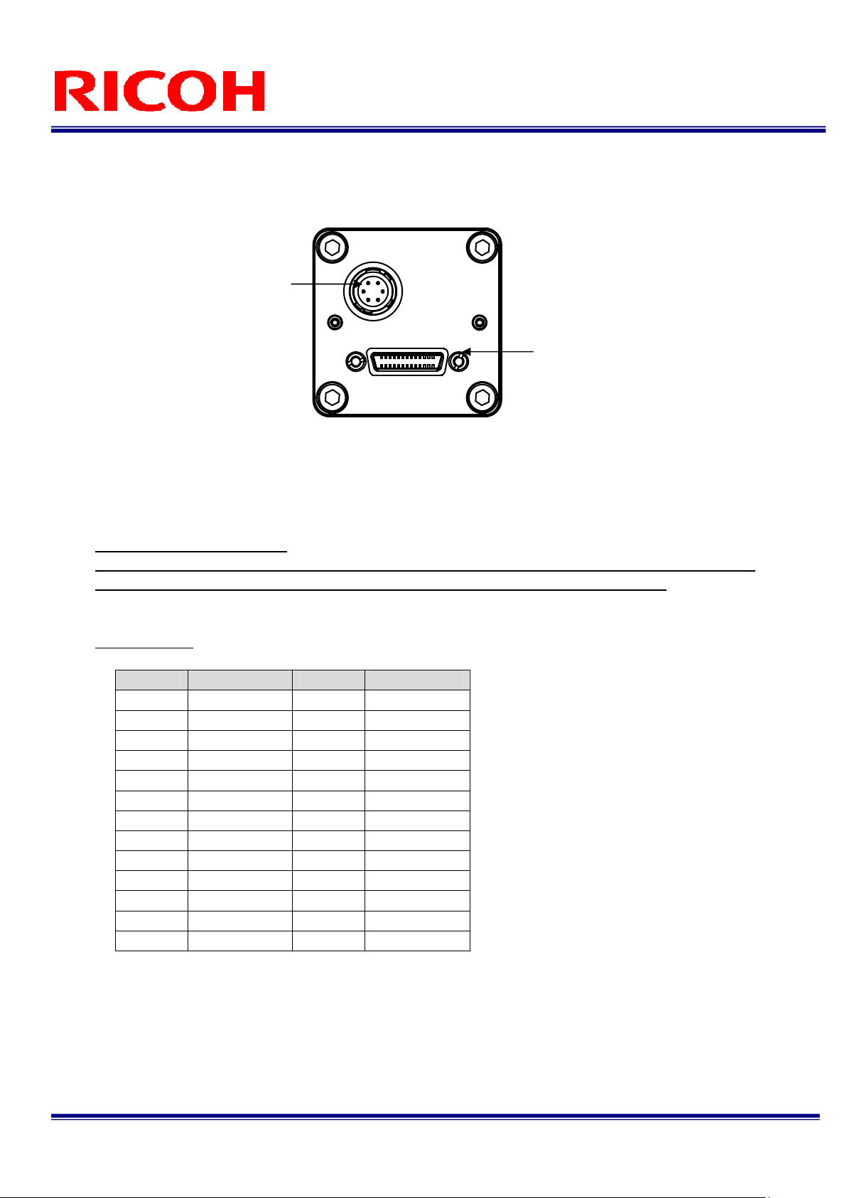
1 Connector Specifications
1.1 Camera Link Connector
SDR (3M) or equivalent
This product is a PoCL type.
When a frame grabber is PoCL compliant, DO NOT SUPPLY POWER FROM THE I/O CONNECTOR.
When a frame grabber is NOT PoCL compliant, supply power from the I/O connector.
Pin Assignment
Power-I/O Connector
Pin No. Signal Name Pin No. Signal Name
1 +12V 14 GND
2 X0- 15 X0+
3 X1- 16 X1+
4 X2- 17 X2+
5 Xclk- 18 Xclk+
6 X3- 19 X3+
7 SerTC+ 20 SerTC-
8 SerTFG- 21 SerTFG+
9 CC1-(TRG) 22 CC1+(TRG)
10 CC2+ 23 CC2-
11 CC3- 24 CC3+
12 CC4+ 25 CC4-
13 GND 26 +12V
Camera Link Connector
FV-L500B1
3/31
User’s Guide Rev. 1.02
Page 4
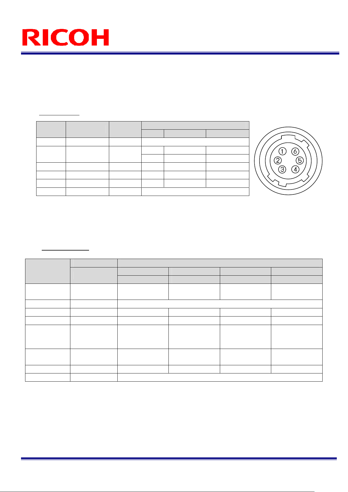
1.2 Power-I/O Connector
HR10A-7R-6PB(Hirose)or equivalent
This connector is for the power supply (12Vdc) and input /output signals.
Use HR10A-7P-6S (Hirose) or equivalent for the cable side.
Pin Assignment
Pin No. Signal Name IN / OUT
1 GND IN 0V
2 I/O-1 IN/OUT
3 I/O-2 OUT
4 I/O-3 OUT
5 I/O-4 OUT OUT 0V +3.3V
6 +12Vdc IN +12Vdc
Input/output signals can be assigned through the camera setting communication (see table 4).
Trigger input signal can be assigned either on Camera Link connector (CC1) or on the No. 2 pin of the
power-I/O connector through the camera setting communication.
IO Signal Patterns
Voltage
Low Voltage High Voltage
IN 0 to +0.99V +2.3 to +3.3V
OUT 0V +3.3V
OUT 0V +3.3V
OUT 0V +3.3V
Command No. HR10A-7R-6PB (Hirose)
Option 0
(Initial Setting)
Option 1 1H For Test Use Only
Option 2 2H OUT/CC4 OUT/CC3 OUT/CC”2 OUT/CC1
Option 3 3H OUT/FVAL OUT/XSG OUT/XSUB OUT/CC1
Option 4 4H
Option 5 5H OUT/XHD
Option 6 6H OUT/VD N/A N/A OUT/HD
Others 7H-FH For Test Use Only
F0H[3..0]
0H IN/TRG N/A N/A OUT/TRG
No.2 Pin No.3 Pin No.4 Pin No.5 Pin
I/O-1 (SP4) I/O-2 (SP3) I/O-3 (SP2) I/O-4 (SP1)
OUT/
OUT/FVAL OUT/LVAL
OUT/EXPDUR
(high-active)
(Exposure)
Right Image Data
(MSB)
OUT/TRG OUT/CC1
Note 1: Output trigger signal has a latency of 30CLK (Approximately 470 nseconds) from input trigger signal.
Note 2: To input trigger signal from the I/O connector, change the setting of 12H.5.
Note 3: EXPDUR becomes high during exposure.
OUT/
Left Image Data
(MSB)
FV-L500B1
4/31
User’s Guide Rev. 1.02
Page 5

1.3 Equivalent Circuit for the Input Pin of the I/O Connector
+3.3V +3.3V
100ohm
On resister Max. = 30ohm
TC7WH241FK
TOSHIBA
10kohm
TRIGGER IN
FV-L500B1
5/31
User’s Guide Rev. 1.02
Page 6
2 Camera Output Timing Charts
2.1 Normal Mode (Setting 10H: 1XX0XXXX)
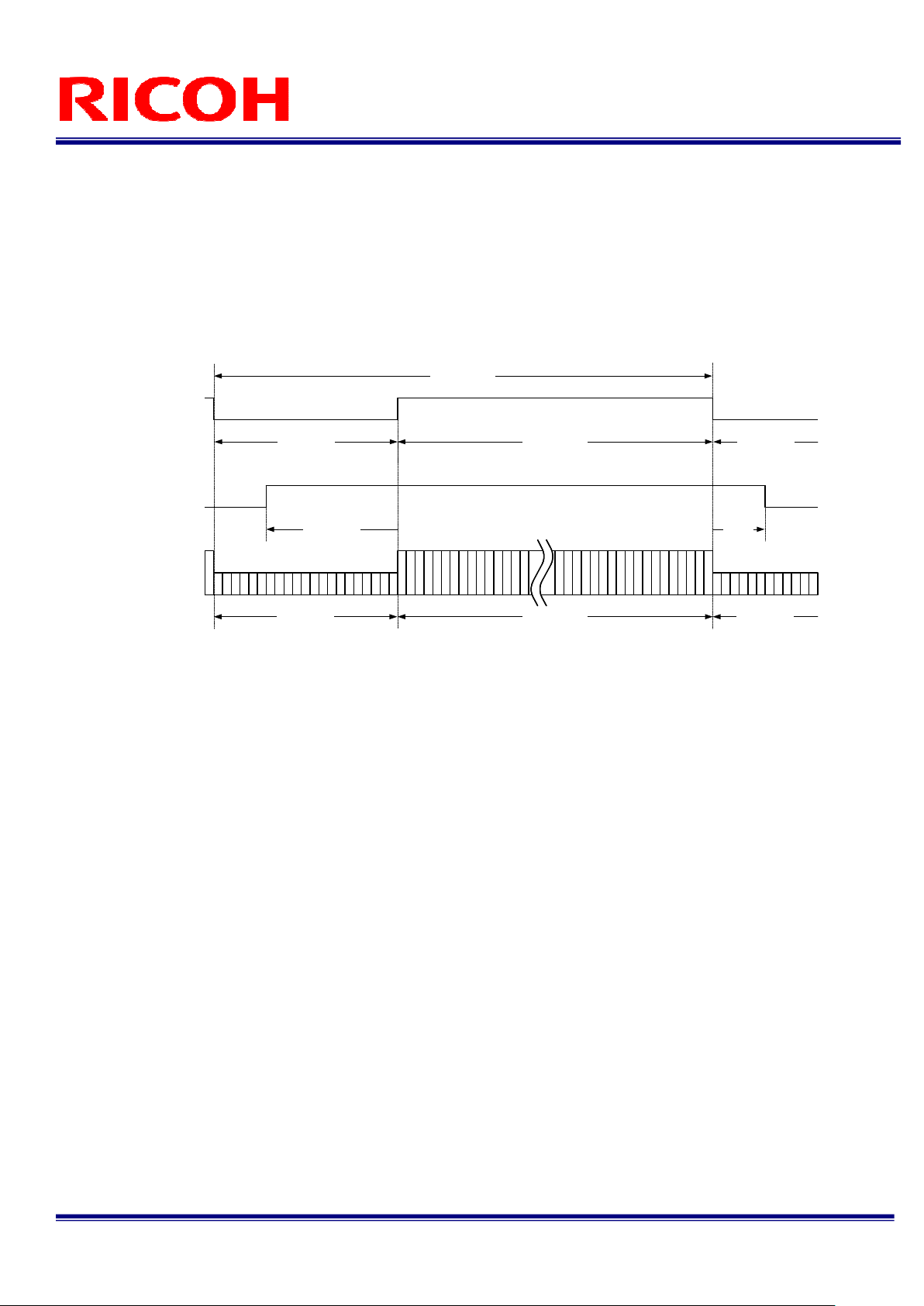
2.1.1 Horizontal Timing
LVAL
DVAL
FVAL
607 CLK
Video out
700 CLK
Horizontal blanking
1924 CLK
One horizontal (1H)
1224 CLK700 CLK
Video output active term
1 CLK = 15.625 ns
700 CLK
93
CLK
700 CLK1224 CLK
Horizontal
blanking
FV-L500B1
6/31
User’s Guide Rev. 1.02
Page 7
2.1.2 Vertical Timing
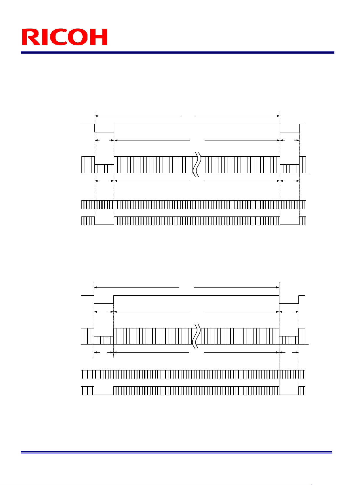
2.1.2.1 Normal Full Scanning (Setting 10H: 1XX00XXX, 11H: XXX0X000)
1 H = 30.063 μs, 16.000 Hz
2079H
FVAL
One vertical (1V)
1
2
2058H21H
Video out
LVAL
Vertical
blanking
Video output active term
2058H21H
DVAL
2.1.2.2 Partial Full Scanning (Setting 10H: 1XX01XXX, 11H: XXX0X000)
1 H = 30.063 μs, 16.100 Hz
FVAL
Video out
LVAL
DVAL
Vertical
blanking
1
2
2066H
2058H8H
2058H8H
Video output active term
One vertical (1V)
※ By transferring the blanking period pixels at a high rate, the frame rate of the partial full scanning can
be increased compared to that of the normal full scanning.
2057
2058
blanking
2057
2058
Vertical
blanking
21H
21H
Vertical
8H
8H
FV-L500B1
7/31
User’s Guide Rev. 1.02
Page 8

2.1.2.3 1/2 Partial Scanning (Setting 10H: 1XX01XXX, 11H: XXX0X001)
1
039
FVAL
Video out
Vertical blanking
LVAL
DVAL
H
856H183H
593
594
856H
Video output active term
One vertical (1V)
1447
1448
2.1.2.4 1/4 Partial Scanning (Setting 10H: 1XX01XXX, 11H: XXX0X010)
1 H = 30.063 μs, 63.968 Hz
5
2
0
H
FVAL
Video out
264H
264H
Vertical blanking
889
890
Video output active term
One vertical (1V)
256H
256H
1143
1144
1 H = 30.063 μs, 32.015 Hz
183
H
183H183H
Vertical blanking
264
H
264
Vertical blanking
H
LVAL
DVAL
FV-L500B1
User’s Guide Rev. 1.02
8/31
Page 9
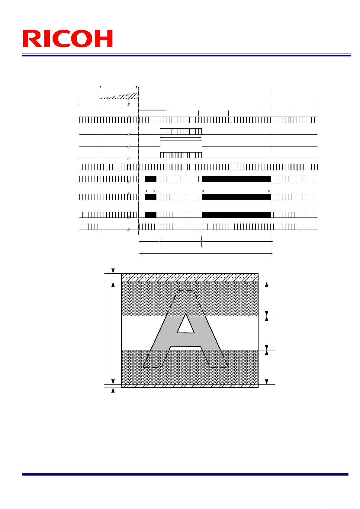
2.1.2.5 Variable Partial Scanning (Setting 10H: 1XX01XXX, 11H: XXX0X111)
EXT_TRIG
FIX_TRIG
(Common)
Exposure time
Internal VD
Internal HD
10 20 30 40 50
Video out
FVAL
Number of the
effective lines [Y]
DVAL
LVAL
V1
V2
High speed
transfer [X+a]
High speed transfer [f+g-X-Y]
V3
SUB
Blanking (Front)
[BLK_F]
Number of the effective lines [Y]
Total number of the line at 1 frame [ TOTAL_LINE]
Blanking (Back)
[BLK_B)
Optical black
+
Dummy bit
CCD effective
lines
Optical black
Blanking
(Front)
Effective
lines
Blanking
(Back)
FV-L500B1
9/31
User’s Guide Rev. 1.02
Page 10
2.2 Binning Mode (Setting 10H: 1XX1XXXX)
2.2.1 Horizontal Timing
LVAL
DVAL
FVAL
607 CLK
Video out
700 CLK
Horizontal blanking
1924 CLK
1224 CLK700 CLK
Video output active term
1 CLK = 15.625 ns
One horizontal (1H)
700 CLK
93
CLK
700 CLK1224 CLK
Horizontal
blanking
FV-L500B1
10/31
User’s Guide Rev. 1.02
Page 11

2.2.2 Vertical Timing
2.2.2.1 Binning Full Scanning (Setting 10H: 1XX10XXX, 11H: XXX0X000)
1 H = 30.063 μs, 32.015 Hz
FVAL
21H
1039H
1018H
One vertical (1V)
10+11
12+13
Video out
21H
Vertical
blanking
Video output active term
1018H
LVAL
DVAL
2.2.2.2 Binning Partial Full Scanning (Setting 10H: 1XX11XXX, 11H: XXX0X000)
1 H = 30.063 μs, 32.077 Hz
FVAL
8
H
1037H
One vertical (1V)
1029H
3+4
1+2
Video out
LVAL
8H
Vertical
blanking
Video output active term
1029H
2042+2043
2055+2056
2044+2045
Vertical
blanking
2057+2058
Vertical
blanking
21H
2
1
8
H
8
H
H
DVAL
FV-L500B1
User’s Guide Rev. 1.02
11/31
Page 12

2.2.2.3 Binning 1/2 Partial Scanning (Setting 10H: 1XX11XXX, 11H: XXX0X001)
1 H = 30.063 μs, 54.890 Hz
6
0
6
FVAL
Video out
Vertical blanking
LVAL
DVAL
H
428H178H
593+594
595+596
428H
Video output active term
One vertical (1V)
178
1445+1446
1447+1448
178H178H
Vertical blanking
2.2.2.4 Binning 1/4 Partial Scanning (Setting 10H: 1XX11XXX, 11H: XXX0X010)
1 H = 30.063 μs, 63.968 Hz
5
2
0
H
FVAL
Video out
392H
392H
Vertical blanking
889+890
891+892
Video output active term
One vertical (1V)
128H
128H
392
1141+1142
1143+1144
392
Vertical blanking
H
H
H
LVAL
DVAL
FV-L500B1
User’s Guide Rev. 1.02
12/31
Page 13

2.3 Data Order on the Camera Link Output
2TAP12bit
XCLK
X3
X2
X1
X0
DA1 DA0
DA0 to DA11: 12bit data for one pixel from the first tap
DB0 to DB11: 12bit data for one pixel from the second tap
2TAP10bit
XCLK
X3
X2
X1
NC
X0
DA1 DA0
DA0 to DA9: 10bit data for one pixel from the first tap
DB0 to DB9: 10bit data for one pixel from the second tap
2TAP8bit
XCLK
X3
X2
X1
X0
DA1 DA0
DA0 to DA7: 8bit data for one pixel from the first tap
DB0 to DB7: 8bit data for one pixel from the second tap
SP DA6DA7DB6DB7
DA6DA7
DB2DB3
DA9DA10
DA8 DA5 DA4 DA3 DA2 DA1 DA0
SP DA6DA7DB6DB7
DA6DA7
DB2DB3
DA9
DA8 DA5 DA4 DA3 DA2 DA1 DA0
SP DA6DA7DB6DB7
DA6DA7
NCNC
DB1DB2
NC
DB9DB0DB1
NC NC
LVALFVALDVAL
NC
DA5 DA4 DA3 DA2 DA1 DA0DB0
DB10DB11
NC NC
NC NC
NC NC NC
DB2DB3DB4DB5LVALFVALDVAL
DA9DA10DA11DB8
DB2DB3DB4DB5LVALFVALDVAL
DA9DB8DB9DB0DB1 DB8DB9
NC
DB1DB2DB3DB4DB5
FV-L500B1
13/31
User’s Guide Rev. 1.02
Page 14

2.4 2 Taps Transferring Image (2XE-1Y)
Tap1
X
1
X
2
Y
1
Y
1
X
1
X
2
Y
2
Y
2
X
1
X
2
Y
H-1
Y
Sep Y = 1
H-1
Sep X = 1
Sep X = 1
X
X
W/2
X
W/2+1
Y
1
Y
1
X
W/2
X
W/2+1
Y
2
Y
2
X
W/2
X
W/2+1
Y
H-1
Y
H-1
W-1
Y
X
W-1
Y
X
W-1
Y
H-1
X
W
1
Y
1
X
W
2
Y
2
X
W
Y
H-1
Tap2
X
1
Y
H
2.5 Pixel Transferring Image
Pixeln of DataA: nth pixel being transferred from the TAP1
Pixeln of DataB: nth pixel being transferred from the TAP2
X
2
Y
H
Pixel1 of
DataA
Pixel2 of
DataA
X
X
X
W/2
X
W/2+1
Y
H
Y
H
W-1
Y
H
W
Y
H
DataB
Pixel1 of
DataB
Pixel2 of
FV-L500B1
14/31
User’s Guide Rev. 1.02
Page 15

3 Camera Operational Mode
3.1 Normal Mode
In this mode, the images are output continuously.
3.1.1 Frame Exposure
I nt er nal VD
CCD
ex p o s u r e
Vi deo out
3.1.2 Electric Shutter
I nt er na l VD
CC D
e x po su r e
Vi de o ou t
Ex pos u r e ti me
Ex po s u r e
t i me
FV-L500B1
15/31
User’s Guide Rev. 1.02
Page 16

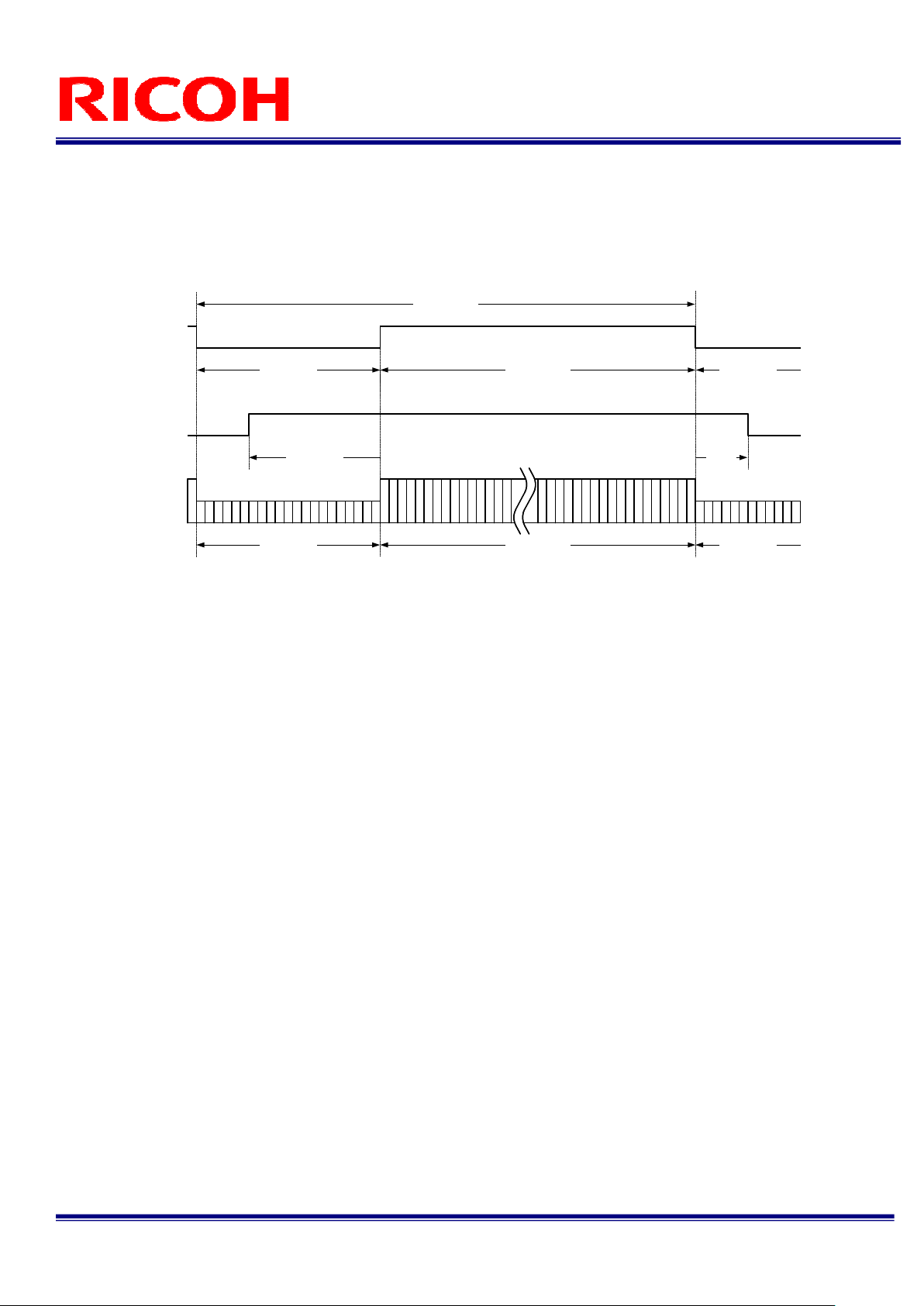
3.2 Pulse Width Trigger Mode
In this “pulse width trigger mode” with positive polarity, the camera exposure starts at the rising edge of the
trigger signal and stops at the falling edge of the trigger signal. Therefore, in the case that the exposure positive
polarity is selected, the actual exposure occurs when the trigger signal is at high state.
3.2.1 Pulse Width Trigger Mode(V-Reset)
Camera mode
Trigger signal
(Positive)
Internal VD
CCD exposure
Video out
FVAL
Normal mode Trigger mode Normal mode
*Note. 2
Max. 1H
Sweep charges
*Note. 3
Exposure
time
Automatically switch to the normal
mode if the pulse width of the
trigger signal is more than
500 mseconds.
*Note. 1
Note 1: The camera does NOT switch to normal mode when the long exposure mode is selected.
This timing chart shows when the long exposure mode selected.
Note 2: The internal VD signal is reset immediately after the exposure is finished as depicted, and the video output
original is sent out according to that reset VD timing.
Note 3: The exposure time is controlled by the pulse width of the trigger signal as depicted.
FV-L500B1
16/31
User’s Guide Rev. 1.02
Page 17

3.2.2 Pulse Width Trigger Mode (Non-Reset)
Camera mode
Trigger signal
(Positive)
Internal VD
CCD exposure
Video out
FVAL
Normal mode Normal modeTrigger mode
Next VD
Sweep charges
*Note. 3
Exposure
time
Next VD
*Note. 2
Automatically switch to the normal
mode if the pulse width of the
trigger signal is more than
500 mseconds.
*Note. 4
*Note. 1
Note 1: The camera does NOT switch to normal mode when the long exposure mode is selected.
This timing chart shows with the long exposure mode selected.
Note 2: The internal VD signal does not reset by the trigger signal.
The video output signal is sent out at the next internal VD timing.
Note 3: The exposure time is controlled by the pulse width of the trigger signal as depicted.
Note 4: The FVAL signal does not output when the exposure by the trigger signal does not exists.
3.2.3 Exposure Timing
Trigger signal
Exposure time
Filtering *Note.1
30 CLK
T1
T1'
SUB
Exposure time: T1' = T1 + 741 CLK
SG
Notes: The trigger signal equal to or shorter than 30 CLK is removed by the filtering system.
Input trigger signal has to be more than 31 CLK pulse width.
The exposure starts 198 CLK after the rising edge of the trigger signal.
(741 CLK)
FV-L500B1
17/31
User’s Guide Rev. 1.02
Page 18

3.3 Edge Preset Trigger Mode
In this “edge preset trigger mode”, the camera exposure starts at the rising edge of the trigger signal like the
“pulse width trigger mode” in the previous sections. However, in this mode, the exposure duration time is based on the
preset value stored by the by the camera setting communication.
3.3.1 Edge Preset Trigger Mode (V-Reset)
Camera mode
Trigger signal
(Rising edge)
Normal mode Normal modeTrigger mode
*Note. 2
Max. 1H
Automatically switch to the normal
mode if the pulse width of the
trigger signal is more than
500 mseconds.
*Note. 1
Internal VD
*Note. 3
Exposure
time
CCD exposure
Video out
FVAL
Note 1: The camera does NOT switch to the normal mode when the long exposure mode is selected.
This timing chart shows when the long exposure mode is selected.
Note 2: The internal VD signal is reset immediately after the exposure is finished as depicted and the video output
signal is sent out according to the reset VD timing.
Note 3: The exposure time is preset by the camera setting communication as “shutter speed”.
FV-L500B1
18/31
User’s Guide Rev. 1.02
Page 19

3.3.2 Edge Preset Trigger Mode (Non-Reset)
Camera mode
Normal mode Trigger mode Normal mode
Trigger signal
(Rising edge)
Internal VD
Next VD Next VD
CCD exposure
*Note. 3
Exposure
time
Video out
FVAL
Note 1: The camera does NOT switch to normal mode when the long exposure mode is selected.
This timing chart shows when the long exposure mode selected.
Note 2: The internal VD signal does not reset by the trigger signal.
The video output signal is sent out at the next internal VD timing.
Note 3: The exposure time is preset by the camera setting communication as “shutter speed”.
Note 4: The FVAL signal does not output when the exposure by the trigger signal does not exists.
3.3.3 Exposure Timing
Trigger signal
Exposure time
30CLK
Filtering *Note.1
SUB
SG
Notes: The trigger signal equal to or shorter than 30 CLK is removed by the filtering system.
Input trigger signal has to be more than 31 CLK pulse width.
The exposure starts198 CLK after the rising edge of the trigger signal.
*Note. 1
Automatically switch to the normal
mode if the pulse width of the
trigger signal is more than
500 mseconds.
*Note. 2
Next VD
*Note. 4
T1'
Exposure time: T1' = Preset electronic shutter
FV-L500B1
19/31
User’s Guide Rev. 1.02
Page 20

3.4 H Reset Mode
Normally, video noise appears when the beginning of trigger signal is applied before finishing the video read-out
of the previous frame. This noise is caused by the SUB pulse, which is activated to clear all residual charges on the
CCD prior to a new exposure. By selecting this “H. Reset Mode”, the camera automatically holds the actual activation of
trigger until the next horizontal blanking period. By doing this, the SUB pulse is activated during the horizontal blanking
period and the noise in image can be avoided.
Due to the principal of this operation, there can be maximum “1 H” of delay of actual trigger signal.
Trigger signal
(Rising edge)
Internal HD
Normal SUB pulse timing
Next HD
SUB pulse
CCD exposure
Noise
Noise
NoiseNoise
Video out
FV-L500B1
20/31
User’s Guide Rev. 1.02
Page 21

4 Communication Protocol
This camera has a communication function that enables external devises, such as a PC, to control the camera’s
functions.
Please use the “R-GigE-Software” communication software, or the following communication protocol to
communicate to the camera:
4.1 Communication Method
UART(RS232C), binary communication
4.2 Communication Settings
4.3 Communication Format
The Sending data format from the PC to the camera is as follows:
The Receiving Data format from the camera is as follows:
After sending the Read Command:
After sending the Write Command:
Settings
Baud Rate 9,600 bps / 38,400 bps
Data Bit 8 bit
Parity None
Stop Bit 1 bit
Flow Control None
SOF
(8bit) (6bit) (1bit) (1bit) (8bit) (8bit)
SOF Data Length
(8bit)
SOF Data Length
(8bit)
Device
Code
(8bit) (n bytes) (8bit)
(8bit) “00” (1 byte) (8bit)
Read/Write
Page
Selection
Data EOF
Receiving Code EOF
Command
Code
Data
Length
Data EOF
(R: 1 byte)
(W: n bytes)
(8bit)
FV-L500B1
21/31
User’s Guide Rev. 1.02
Page 22

The description of the format is as follows.
Name Descriptions
SOF Start of Frame. Always set or receive the value as “02H”
Device Code This indicates the destination of communication.
Set “000000” when accessing the camera’s function settings
Set “100000” when accessing the camera’s extended function settings.
Please refer to the “Camera Command List” and “Description of the Camera Control
Commands”.
Read / Write This specifies “Read” or “Write” to command numbers.
Set (or receive) “0” to send the read command.
Set (or receive) “1” to send the write command.
Page
Selection
Command
Code
Data Length This indicates the data length (unit: byte).
Data This indicates write data or read data according to command type.
EOF End of Frame. Always set or receive the value as “03H”
Receiving
Code
This specifies page selection (access selection to registers or EEPROM) of command.
Set “0” to access the command register of the camera.
Read command: To obtain the current data from the command register.
Write command: To set a data into the command register.
The previously stored data is replaced by this data. However, the data in the EEPROM is not
replaced.
Set ”1” to access the EEPROM of the camera.
Read command: To read stored data from the EEPROM.
Write command: To store data into the EEPROM as default value.
The camera returns the receiving code “01H” to the PC after storing data in the EEPROM.
This indicates the contents of the data sent or received. Refer to the following page for the
details.
Receiving Frame:
The data length is dependent on each read command sent.
The data length is defined as “00H” when sending the write command.
The data length of error response is defined as “00H”.
Sending frame:
The data length is 1 byte dummy data when sending the read command, and that data is
not referenced.
The data length is dependent on each “write command” sent.
This indicates results of the command sent
01H: OK (ACK), 10H: NG (NAC),
11H: Connection error with peripheral device
FV-L500B1
22/31
User’s Guide Rev. 1.02
Page 23

【
Example Code
】Reading the data from the command 00H
Command to send: 02H, 00H, 00H, 01H, 00H, 03H
SOF Device Code Read/Write Page Selection Command Code Data Length Data EOF
(8bit) (6bit) (1bit) (1bit) (8bit) (8bit) (1byte) (8bit)
02H 00H 00H 01H 00H 03H
Command to receive upon a successful communication: 02H, 01H, 00H, 03H (assuming the data is 00H)
SOF Data Length Data EOF
(8bit) (8bit) (n bytes) (8bit)
02H 01H 00H 03H
【Sequence for the saving commands to the EEPROM】
Please use the following sequence for saving the commands to the EEPROM.
1) Set “1” to the 80H.0 to enable writing to the EEPROM.
2) Send the save data with the page selection “1”.
3) The camera sends back one of the following receiving codes after writing the EEPROM.
01H: OK
10H: NG
4) 80.0H is cleared to “0” automatically after writing the EEPROM.
Note1: The data cannot be saved to the EEPROM when 80H.0 is “0”.
Note2: When saving the consecutive sequence of commands, the above steps, 1) to 4), are necessary only once.
i.e.) saving the commands “10H, 11H, 12H, 13H”, or “22H, 23H, 24H”, etc.
Note3: When saving the non-consecutive sequence of commands, the above steps, 1) to 4), are necessary for the
same number of times.
i.e.) saving the commands “10H, 13H, 19H, 1BH” or “20H, 23H, 25H”, etc.
FV-L500B1
23/31
User’s Guide Rev. 1.02
Page 24

4.4 Camera Control Command
4.4.1 Camera Command List
The data unit of the each command is 1 byte (8bit).
The data can be saved to the EEPROM if there is an “X” in the “Save to EEPROM” column in the
following list.
The camera initializes based on the stored data in the EEPROM when the power is applied.
Command
No.
00 to 0FH
10H R/W
11H R/W
12H R/W
13H Reserved - -
14H R/W
15 to 1FH
20H R/W
21H R/W
22H R/W
23H R/W
24H R/W
25H R/W
26H R/W
27H R/W
28H R/W
29-2FH Reserved - -
30H R/W
31H X Digital gain 0 to 255
32H R/W
33 to 37H
38H R/W
39 to 3DH
3EH R/W X
3FH R/W X
40 to 53H R/W X
68H R/W
69H Reserved - -
6AH R/W
6BH R/W
6CH R/W
6DH R/W
6E to 77H
78H R/W
79H R/W
7A to FFH
80H R/W
R/W
Save to
EEPROM
Reserved - -
X Camera function mode 1 (8bit: D[70]) 9
X Camera function mode 2 (8bit: D[70]) 0
X Camera function mode 3 (8bit: D[70]) 0
X Communication mode (8bit: D[70]) 1
Reserved - -
X Exposure time (H) of the electronic shutter (16bit: D[70])
X Exposure time (H) of the electronic shutter (16bit: D[158])
X Exposure time (CLK) of the electronic shutter (16bit: D[70])
X Exposure time (CLK) of the electronic shutter (16bit: D[158])
X Start line of the variable partial scanning (16bit: D[70])
X Start line of the variable partial scanning (16bit: D[158])
X Effective lines of the variable partial scanning (16bit: D[70])
X Effective lines of the variable partial scanning (16bit: D[158])
X Delay time for the trigger (8bit: D[70]) 0 0 to 31
X CDS gain (8bit: D[70]) 0 0 to 255
X Gain offset (6bit: D[50])
Reserved - -
X Clamp level (8bit: D[70]) 0 0 to 255
Reserved - -
Test pattern level (10bit: D[70])
Test pattern level (10bit: D[98])
Reserved
X Digital clamp (8bit: D[7..0]) 0
X Manual digital clamp (Left) (16bit D[7..0])
X Manual digital clamp (Left) (16bit D[15..8])
X Manual digital clamp (Right) (16bit D[7..0])
X Manual digital clamp (Right) (16bit D[15..8])
Reserved - -
X Test pattern selection (8bit: D[7..0]) 0 -
X Image effect selection (8bit: D[7..0]) 0 -
Reserved - -
EEPROM control (8bit: D[70])
Function Initial Data Data Range
0 0 to 4095
0 0 to 1923
0 0 to 2057
2058 0 to 2058
The Factory
Adjusted
Value
4095 0 to 4095
- -
0 0 to 1023
0 0 to 1023
0 to 255
FV-L500B1
24/31
User’s Guide Rev. 1.02
Page 25

81 to EFH
Command
No.
F0H R/W
F1 to FFH
Reserved - -
R/W
Save to
EEPROM
IO connector signals(8bit: D[70])
Reserved - -
Function Initial Data Data Range
FV-L500B1
25/31
User’s Guide Rev. 1.02
Page 26
4.4.2 Descriptions of the Camera Control Commands
(The underline settings are the factory default settings)
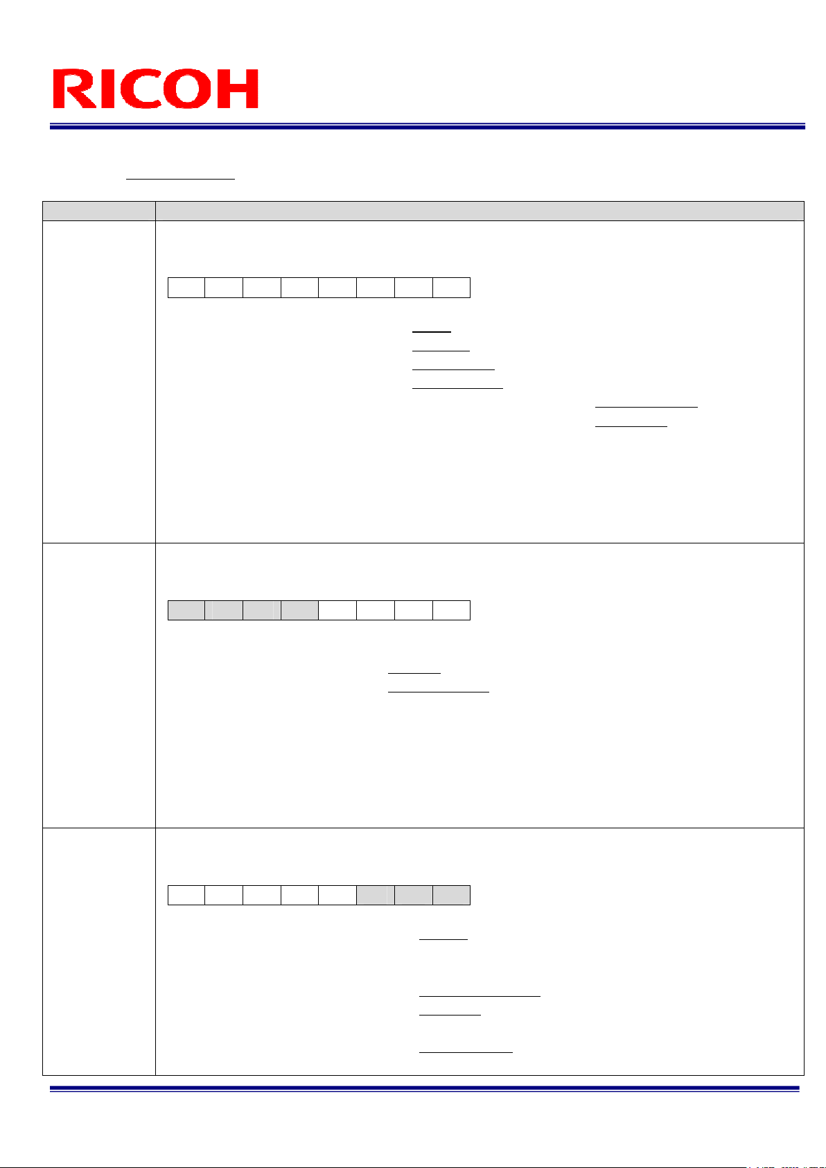
Command No. Command Descriptions
[Camera function mode setting 1] Initial data: 09H
This sets the following camera function mode.
D[70]
D7 D6 D5 D4 D3 D2 D1 D0
D7: Continuous / Trigger Mode 0: Auto 1: Manual
D6: Trigger Polarity 0: Positive 1: Negative
10H:
MOD1[70]
11H:
MOD2[70]
12H:
MOD3[70]
D5: Trigger Mode 0: Edge Preset 1: Pulse Width
D4: Binning Mode 0: OFF (Normal) 1: ON (Binning)
D3: Scanning Mode 0: Full scanning 1: Partial scanning
D2~D0: Reset Mode 000: Non-Reset 001: V-Reset
010~111: No function
(Prohibited setting. Please do not use these)
When D7 is set to “0: Auto”, a camera will detect its operational mode based on the input trigger signal.
If the input trigger signal is kept at high, the camera operates in the continuous mode, assuming the trigger polarity
is set to positive.
[Camera function mode setting 2] Initial data: 0
This sets the following camera function modes.
D[70]
D7 D6 D5 D4 D3 D2 D1 D0
D7~D4: No Function Set always “0000”
D3 Function Mode 0: Trigger 1: Normal
D2~D0: Partial Scanning 000: Full scanning 001: 1/2 partial scanning
010: 1/4 partial scanning
011~110: No function
(Prohibited setting. Do not set these values)
111: Variable partial scanning
Function mode is enabled when the “Continuous/Trigger” mode selection (MOD[7] is manual (set as 1).
No video output without the trigger signal input while the camera works with the trigger mode.
[Camera function mode setting 3] Initial data: 0
This sets the following camera function modes.
D[70]
D7 D6 D5 D4 D3 D2 D1 D0
D7~D6: Video Out 00: 10bit 01: 8bit
10: 12bit
11: No function (Prohibited setting. Do not set these values)
D5: Trigger-in connector selection 0: Camera Link (CC1) 1: /IO connector (No.2 Pin)
D4~D3: Exposure Start Mode 00: Normal 01: Reserved trigger
10 ~11: H reset
D2~D0:
No Function Set always “000”
FV-L500B1
26/31
User’s Guide Rev. 1.02
Page 27

Command No. Command Descriptions
[Communication mode] Initial Data: 01H
This sets the communication modes.
D[70]
D7 D6 D5 D4 D3 D2 D1 D0
14H:
UART[70]
20H:
SVR[70]
21H:
SVR[158]
22H:
SHR[70]
23H:
SHR[158]
24H:
PSR[7..0]
25H:
PSR[158]
D7~D2: No Function Set always “000000”
D1~D0: Communication Mode 00: 38,400 bps 01: 9,600 bps
[Exposure time (H) of the electronic shutter]
Initial Data: SVR[150] = 0, Data Range: 0 to 4095
Sets the preset shutter speed (or CCD exposure time) for electronic shutter.
The preset shutter speed is defined by the following formula.
Exposure time (shutter speed) = SVR[150] x (1H cycle time) + SHR[150] x (1CLK cycle time)
Notes:
1. The camera works with the shutter off position (maximum frame exposure time) when both SVR and
SHR are set at “0”.
2. The camera works with the minimum shutter speed when this value is set to 0 and the value of SHR is
set between 1 and 600.
3. The value is replaced with 4095 automatically when the value set greater than 4095.
[Exposure time (CLK) of the electronic shutter]
Initial Data: SHR[150] = 0, Data Range: 0 to 1923
Sets the preset shutter speed (or CCD exposure time) for electronic shutter.
The previous section, the preset shutter speed is defined by the following formula:
Preset shutter speed = SVR[150] x (1H cycle time) + SHR[150] x (1CLK cycle time)
Notes:
1. The camera works with the shutter off position (maximum frame exposure time) when both SVR and
SHR are set at “0”.
2. The camera works with the minimum shutter speed when SVR is set to 0 and this value is set
between 1 and 600.
3. The value replaces by 1923 automatically when the value set greater than 1923.
[Start line of the variable partial scanning]
Initial Data: PSR[150] = 0, Data Range: 0 to 2057
This sets the start line number of the variable partial scanning area.
Actual start line of the partial scanning = this value + 1
Notes:
1. The value replaces by 2057 automatically when the value set greater than 2057.
2. The camera works with full scanning mode when the value of (PSR[ ] + PWR[ ]) is greater than 2058.
10 to 11: No function (Prohibited setting. Do not set these
values)
FV-L500B1
27/31
User’s Guide Rev. 1.02
Page 28

Command No. Command Descriptions
[Effective line numbers in the variable partial scanning]
Initial Data: PWR[150] = 2058, Data Range: 0 to 2058
26H:
PWR[70]
27H:
PWR[158]
28H:
DLY[70]
30H
PGA[70]
31H
DGB[70]
32H
GOFS[70]
38H:
CLAMP[70]
3EH: TP0[70]
3FH:TP0[98]
This sets the number of the total effective lines (image height) in the variable partial scanning mode.
Notes:
1. The value replaces by 2058 automatically when the value set greater than 2058.
2. The camera works with full scanning mode when the value of (PSR[ ] + PWR[ ]) is greater than 2058.
[Delay time for the trigger] Initial Data: DLY[70] = 0, Data Range: 0 to255
Sets the delay time from the trigger input signal to the start of the exposure.
Delay time (us) = 128 x CLK x DLY[70] = 2.000 (us) x DLY[70], where CLK = pixel clock
[CDS gain] Initial Data: PGA[70] = 0, data range: 0 to 255
Sets the CDS gain (programmable analog gain).
CDS gain = 11.1 + 0.0359 x (PGA[7..0] x 2 + GOFS[7..0]) (dB)
*GOFS[7...0]: The gain offset (The value of the address 32H)
[Digital gain] Initial Data: The factory adjusted value, Data Range: 0 to 255
Sets the digital gain.
Output level = (input level – CLAMP[70] x 16 – (CDS_CLAMP_L[9..0] + CDS_CLAMP_R[9..0]) / 2) x
(1 + (DGB[7..0] + GOFS[7..0]) / 128) + CLAMP[7..0] X 16 +
(CDS_CLAMP_L[9..0] + CDS_CLAMP_R[9..0]) / 2
*CLAMP[7...0]: clamp level (command no. 38H)
*GOFS[7...0]: gain offset (command no. 32H)
*CDS_CLAMP_L[9...0]: CDS clamp left (command no. CC-CDH)
*CDS_CLAMP_R[9...0] CDS clamp right (command no. CE~CFH)
[Gain offset] Initial Data: The factory adjusted value, Data Range: 0 to 255
[Clamp level] Initial Data: CLAMP[70] = 0, Data Range: 0 to 31
This sets the clamp level value of the black level.
Clamp level (Left) = CLAMP[7..0] x 16 + CDS Clamp (Left)
Clamp level (Right) = CLMAP[70] x 16 + CDS Clamp (Right)
The value replaces by 31 automatically when the value set greater than 31.
[Test pattern level] Initial data: 4095, data range: 0 to 4095
Sets the output level of the test pattern 4: Raster (variable level) in 10-bit output format.
FV-L500B1
28/31
User’s Guide Rev. 1.02
Page 29

Command No. Command Descriptions
[Digital clamp] Initial data: DIGITAL_CLAMP[7..0] = 0
Sets the digital clamp.
D[7..0]
D7 D6 D5 D4 D3 D2 D1 D0
D7 to D5: No function Always set as “000”
68H:
DIGITAL_
CLAMP[70]
6AH:
MD_CLAMP_L
[70]
6BH:
MD_CLAMP_L
[158]
6CH:
MD_CLAMP_R
[70]
6CH:
MD_CLAMP_R
[158]
78H:
TESTP[70]
D4: Mirror image 0: Normal image 1: Mirror image
D3: No function Always set as “0”
D2: Clamp mode 0: Auto adjust 1: Manual adjust
D1 to D0: No function Always set as “00”
The following two settings have to be set when the “manual adjust” is selected at the clamp mode:
Manual digital clamp (Left): MD-CLAMP_L[15..0] (6A & 6BH)
Manual digital clamp (Right): MD_CLAMP_R[15..0] (6C & 6DH)
[Manual digital clamp (Left)]
Initial data: MD_CLAMP_L[15..0] = The factory adjusted value, data range: 0 to 1023
Sets the manual digital clamp for the left side of the image when the manual adjust is selected at the digital
clamp (68H).
[Manual digital clamp (Right)]
Initial data: MD_CLAMP_R[15..0] = The factory adjusted value, data range: 0 to 1023
Sets the manual digital clamp for the right side of the image when the manual adjust is selected at the digital
clamp (68H).
[Test pattern selection] Initial data: TESTP[7..0] = 0
Sets the test pattern output from the camera.
D[7..0]
D7 D6 D5 D4 D3 D2 D1 D0
00H: Video output 01H: Gray scale
02H: Ramp wave 03H: Uniform gray level (100% white)
04H: Uniform gray level (variable level) 05H: Color bar (RGB bayer)
Others: Black
FV-L500B1
User’s Guide Rev. 1.02
29/31
Page 30

Command No. Command Descriptions
[Image effect selection] Initial data: EFFCT[7..0] = 0
Sets the image effect.
D[7..0]
D7 D6 D5 D4 D3 D2 D1 D0
00H: No effect (Original video) 01H: 11bit gradation
79H:
EFFCT[70]
80H:
E2P[70]
F0H:
OUTSEL[70]
02H: 10bit gradation 03H: 9bit gradation
04H: 8bit gradation 05H: 7bit gradation
06H: 6bit gradation 07H: 5bit gradation
08H: 4bit gradation 09H: 3bit gradation
0AH: 2bit gradation 0BH: 1bit gradation
0C to FEH: No function
FFH: MSB-LSB reverse
[EEPROM control] Initial data: E2P[70] = 0
Sets the image effect.
D[7..0]
D7 D6 D5 D4 D3 D2 D1 D0
D7~D2: No function Always set as “000000”
D1: Register synchronous update with the EEPROM data 0: Prohibited 1: Accept
D0: Write control to the EEPROM 0: Prohibited 1: Accept
[EEPROM control] Initial data: OUTSEL[70] = the value of C0H
Sets the image effect.
D[7..0]
D7 D6 D5 D4 D3 D2 D1 D0
D7~D4: No function Always set as “000000”
D3~D0: The signals of the power/IO
connector selection
Initial data: 0000, data range: 0000~0111
Please refer to “The Signals of the Power/IO Connector”
FV-L500B1
30/31
User’s Guide Rev. 1.02
Page 31

5 Revision History
Rev Date Changes Note
1.00 2012/06/15 Initial Release
1.01 2012/07/13 Updated
Document Title
Communication Protocol
78H Test pattern
79H Pasteurization
Added 3E-3FH Test pattern variable level
1.02 2012/09/27 Updated
Power-I/O Connector
Power supply through No.6 pin of the power-I/O connector became available.
RICOH COMPANY, LTD.
URL http://www.ricoh.com/fa_security/
FV-L500B1
User’s Guide Rev. 1.02
31/31
 Loading...